High Integrity Pressure Protection Systems (HIPPS) For oil & gas installations
PRECISION I RELIABILITY I PERFORMANCE
FOLD
FOLD
06
01
07
09
08
10
1211
13
0204
03
05
16
17
18
19
20
1415
21
Contents
Introduction 01
Benefits of HIPPS 02
HIPPS vs Emergency Shut Down 02
Delivery Wheel 03
Why the Severn Glocon Group? 03
How does HIPPS work 04
HIPPS 06
Electronic HIPPS for Topside 06
Mechanical HIPPS for Subsea 07
Safety Systems & HAZOP Study 08 – 09
Integrated HIPPS Benefits 08 – 09
FOLD
FOLD
The Severn Glocon Group is able tooffer integrated High Integrity PressureProtection Systems (HIPPS) for oil andgas installations. Rated SIL 1– 4, theyare designed and built in accordancewith IEC 61508 and IEC 61511 safetyinstrumented systems (SIS) standardsand provide a dual electronic and mechanical redundancy solution.
HIGH INTEGRITY PRESSURE PROTECTION SYSTEMS
High Integrity Pressure Protection Systems 01
FOLD
FOLD
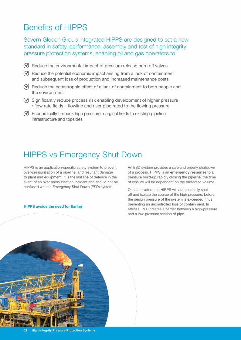
HIPPS is an application-specific safety system to prevent over-pressurisation of a pipeline, and resultant damage to plant and equipment. It is the last line of defence in the event of an over pressurisation incident and should not be confused with an Emergency Shut Down (ESD) system.
HIPPS vs Emergency Shut DownAn ESD system provides a safe and orderly shutdown of a process. HIPPS is an emergency response to a pressure build-up rapidly closing the pipeline, the time of closure will be dependent on the protected volume.
Once activated, the HIPPS will automatically shut off and isolate the source of the high pressure, before the design pressure of the system is exceeded, thus preventing an uncontrolled loss of containment. In effect HIPPS creates a barrier between a high-pressure and a low-pressure section of pipe.
Reduce the environmental impact of pressure release burn off valves
Reduce the potential economic impact arising from a lack of containment and subsequent loss of production and increased maintenance costs
Reduce the catastrophic effect of a lack of containment to both people and the environment
Significantly reduce process risk enabling development of higher pressure / flow rate fields – flowline and riser pipe rated to the flowing pressure
Economically tie-back high pressure marginal fields to existing pipeline infrastructure and topsides
02 High Integrity Pressure Protection Systems
Benefits of HIPPSSevern Glocon Group integrated HIPPS are designed to set a new standard in safety, performance, assembly and test of high integrity pressure protection systems, enabling oil and gas operators to:
FOLD
FOLD
HIPPS avoids the need for flaring

High Integrity Pressure Protection Systems 03
Delivery WheelThe Severn Glocon Group fully satisfy HIPPS requirements by ensuring that the level of safety, quality and service is delivered at all levels.
FOLD
FOLD
Functional Safety Management Certified proof testing, inspection plans & working procedures
Ongoing system & inspection support
Full product supply of integrated system delivering customer flexibility
IEC 61508 & 61511SIL Verification tested system
Fully variable components NO WEAK LINK reducing Common Cause Factor
Why the Severn Glocon Group?The Severn Glocon Group is able to offer a full ‘Functional Safety Management’ service.
It has a dedicated HIPPS design, assembly and test facility.
All HIPPS projects are performed using a standard design methodology, ensuring consistency of interpretation of IEC 61508 and IEC 61511, and HAZOP Study; under the responsibility of Certified Functional Safety Professionals.
The Severn Glocon Group HIPPS facility enables Integrated Factory Acceptance Test (IFAT) bringing together the HIPPS components and customer and Classification Society in a single space for validation and testing of the HIPPS.

0404
LOGIC SOLVER
0203
0101 01
COMMS LINK
PRESSURE TRANSMITTERS
SOLENOIDSSOLENOIDS
FINAL ELEMENTS05 05
04 High Integrity Pressure Protection Systems
How does HIPPS workHIPPS is an application-specific safety system to prevent over pressurisation of a pipeline by rapidly closing the final elements to shut off the pipeline.

0404
LOGIC SOLVER
0203
0101 01
COMMS LINK
PRESSURE TRANSMITTERS
SOLENOIDSSOLENOIDS
FINAL ELEMENTS05 05
High Integrity Pressure Protection Systems 05
Pressure Transmitters
Pressure transmitters monitor the pipeline pressure against a pre-defined limit. The number and types of transmitters and their voting systems is a function of the SIL rating. In a HIPPS pressure transmitters are configured for 2oo3 voting to achieve SIL 3.
Logic Solver
The HIPPS logic solver captures signals from the pressure transmitters, and performs a 2oo3 voting logic, before activating the solenoids and closing the pipeline. Two types of TÜV certified logic solvers are available: PLC and hardwired, both provide scalable redundancy.
Comms Link
Separate Failsafe communications links for each of the three pressure transmitters (inputs) and each of the four solenoids (outputs), together with communications to the Control Module.
Solenoids
Two different types of valve solenoids, configured 2oo2, are used to close the final elements. They are optimised to provide fast reliable stroking / partial stroke testing over an extended service life.
Final Elements
The final element closes the pipeline. The valves are piggable, and designed for in-line maintenance.
01 03
04
02
05
06 High Integrity Pressure Protection Systems
HIPPSHIPPS is a complete functional loop comprising three main elements: a final element (valve and actuator) to isolate the pipeline, pressure sensors (initiators) to detect a pressure build-up and a logic solver to check the pressure signal is real rather than spurious, thus avoiding ‘no cause’ HIPPS activation. Given the safety critical nature of the HIPPS, the system is normally duplicated with two final elements.
The Severn Glocon Group supplies two types of HIPPS: Electronic and Mechanical.
Electronic HIPPS for Topside applications
Electronic initiators to detect an increase in pressure (pressure transducers, PT).
Hard wired solid state, or PLC based, Logic Solver to process signals from the Initiators and perform “two out of three” (2oo3) voting, diagnostics, and partial stroke testing.
Final Element to perform the action needed to isolate the high-pressure zone, allowing a safe shutdown. The final elements, valves and actuators, have proven track record in critical safety systems.
Benefits of electronic HIPPS include
Sensor connection to pipeline including remote sensors
One sensing unit for parallel streams
Logic Solver unit 2oo3 configuration
Ability to access status information and diagnostics
Enables partial stroke testing
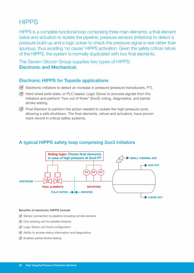
Voting logic: Closes final elements in case of high pressure at 2oo3 PT
FINAL ELEMENTS INITIATORS
LIQUID OUT
GAS OUT
SMALL THERMAL SRV
PTPTPT
UPSTREAM
FULLY RATED DERATED
A typical HIPPS safety loop comprising 2oo3 initiators

High Integrity Pressure Protection Systems 07
Dual redundancy HIPPS for Subsea applications
For Subsea applications, Severn Glocon offers a fully integrated, dual redundancy HIPPS combining independent electronic and mechanical systems.
In addition to the Electronic HIPPS’s pressure transmitters, the Mechanical HIPPS uses mechanical initiators to detect an increase in pressure (pressure sensors, PS), providing an additional level of protection in the event of over pressurization.
Two pairs of pressure sensors are linked to two final elements in series. Each final element has mechanical initiators with ‘one out of two’ (1oo2) voting. This standalone system has no external power requirements.
The Subsea HIPPS combines the benefit of both electronic and mechanical activation. The additional pressure protection offered by mechanical HIPPS comprises two pipeline isolation valves, each controlled by two independent hydraulic control sub-systems. The valves are arranged in series within the pipeline, with each valve capable of independently isolating the flow when closed.
Benefits of electrical and mechanical HIPPS include
Combined electronic and mechanical pressure protection
Independent operation
Simple operation of mechanical HIPPS
Partial and full stroke testing
A dual redundancy electrical and mechanical HIPPS
eHIPPS Voting logic, 2oo3
UPSTREAM
FINAL ELEMENTSINITIATORS
eHIPPSINITIATORS
hHIPPS
FULLY RATED
LAYERED HIPPS system
DERATED
PTPTPT PSPS PSPS

FOLD
FOLD
08 High Integrity Pressure Protection Systems
Integrated HIPPS BenefitsSevern Glocon Group integrated HIPPS offers a number of safety and operational advantages over other suppliers. These include:
Safety
Combined electronic and mechanical HIPPS provides an additional level of redundancy, and safety, due to the variance between the pressure detection parts used.
HIPPS closure time customised to reflect actual rather than theoretical requirements – the industry reference a 2 second closure, however, this may jeopardies other parts of the process (the actual required closure time needs to be qualified). It is imperative that required speed of closure for the final elements is calculated based on the protected volume, correct speed of operation is critical to ensure a surge is not created, compounding the initial problem.
Integrated design, assembly and test – the Severn Glocon Group fully understands the importance of the architectural constraints of IEC 61508, which is a non-prescriptive performance based standard for functional safety systems but not specific to the Oil and Gas Industry, and IEC 61511 which is more relevant to the Oil and Gas Industry.
Safety SystemsDesign of the HIPPS safety system is in accordance with International Electrotechical Commission standard IEC 61508 (Functional safety of electrical / electronic / programmable electronic safety related systems) and IEC 61511 (Safety instrumented systems for the process industry sector) international standards. These provide a total life cycle approach to safety instrumented systems.
Risk Graph based on HAZOP defines SIL
HAZOP StudyThe starting point for designing the HIPPS is a detailed Hazard and Operability (HAZOP) study. This is a structured and systematic examination of a planned or existing process or operation. Its objective is to identify and assess problems that may represent risks to personnel, equipment, and the process.
CA
CB FA
FB
FA
FB
FA
FB
CC
PA
W3 W2 W1
PB
PA
PB
PA
PB
PA
PB
CD
START
A
A
A
0 0
01
1
1
2
2
2
3
3
3
4
4B
C = Consequence parameter CA = Minor injury CB = Serious injury to one or more, death to one CC = Death to several people CD = Very many people killed
F = Frequency of exposure parameter FA = Rare to more often exposure FB = Frequently to continuously
P = Possibility of escape PA = Possible under certain conditions PB = Almost impossible
W = Likelihood of event W1 = a relatively slight probability W2= a relatively medium probability W3= a relatively high probability

FOLD
FOLD
High Integrity Pressure Protection Systems 09
Operational
Isolation valves maintained in-line, avoiding the cost and disruption of removing the valve during process maintenance. In addition, the valve design permits the pipeline to be pig inspected.
Periodic testing and automated diagnostics together with full and partial stroke testing to run diagnostics on the critical control components in the shutdown circuit, to ensure the integrity of the safety loop.
The Risk Reduction Factor (RRF) or Probability of Failure on Demand (PFD) of the system must be better than that required by the application specific SIL level. One of the outcomes for the HAZOP is a risk graph that is used to define the safety integrity level (SIL) for the project. SIL is defined as a relative level of risk-reduction provided by a safety function, or to specify a target level of risk reduction.
The IEC 61508 standard defines four levels of SILs: SIL 1 being the lowest and SIL 4 the highest. A SIL is determined based on a number of quantitative factors, in combination with qualitative factors such as development process and safety life cycle management. In effect, defining the degree of redundancy required.
SAFETY INTEGRITY
LEVEL
PROBABILITY OF FAILURE ON DEMAND
RISK REDUCTION
FACTOR
ARCHITECTURE FOR FINAL ELEMENTS
& SENSORS
ARCHITECTURE WHEN “PROVEN IN USE”
SIL PFD RRF HWFT REDUNDANCY HWFT REDUNDANCY
0 No safety requirements (at all)
A No safety requirements (e.g. only a procedure)
1 ≥10-2 to <10-1 > 10 to ≤100 0 1oo1 0 1oo1
2 ≥10-3 to <10-2 > 100 to ≤1.000 1 1oo2 0 1oo1
3 ≥10-4 to <10-3 > 1.000 to ≤10.000 2 1oo3 1 1oo2
4 ≥10-5 to <10-4 > 10.000 or better Special requirements to IEC 61508
B A single safety system is not sufficient (even with redundant components)
SIL required defines the design of the safety loop

High Integrity Pressure Protection Systems (HIPPS) For oil & gas installations
FOLD
FOLD
01 Severn Glocon Group plc Gloucester England UK
Mars Valve UK Gloucester England UK
L.B.Bentley Stroud England UK
Ionex SG Nailsworth England UK
02 Severn Unival Brighouse England UK
03 Severn Subsea Technologies Redruth England UK
04 Severn Unival Widnes England UK
05 Severn Ball Valves Aberdeen Scotland UK
06 Severn Norway Bergen Norway
07 Severn Glocon Atlantic Canada Newfoundland Canada
08 Severn Glocon Calgary Canada
09 Severn Glocon Houston Texas USA
10 Severn Glocon Rio Brazil
11 Severn Valve Solutions Basra Iraq
12 Severn Glocon Saudi Arabia
13 Severn Glocon Doha Qatar
14 QTRCO SG Dubai
15 Severn Glocon FZE Dubai
16 Severn Glocon India Chennai India
17 Severn Glocon Kuala Lumpur Malaysia
18 Severn Glocon Australia Perth Australia
19 Severn Glocon Beijing China
20 Severn Glocon Seoul Korea
21 Severn Glocon Tokyo Japan
06
01
07
09
08
10
1211
13
0204
03
05
16
17
18
19
20
1415
21
The Severn Glocon Group policy is one of continuous improvement and
we reserve the right to modify these specification details without notice. Brochure design by verycreativepeople.co.uk
PRECISION I RELIABILITY I PERFORMANCE
Olympus Park Quedgeley Gloucester Gloucestershire GL2 4NF England
T. +44 (0)845 223 2040 F. +44 (0)845 223 2041 [email protected] www.severnglocon.com
Recommended