1-100 HP (230V) n 1-400 HP (460V)1-10 HP (575V) n 15-250 HP (690V)
A510Heavy Duty AC Drive
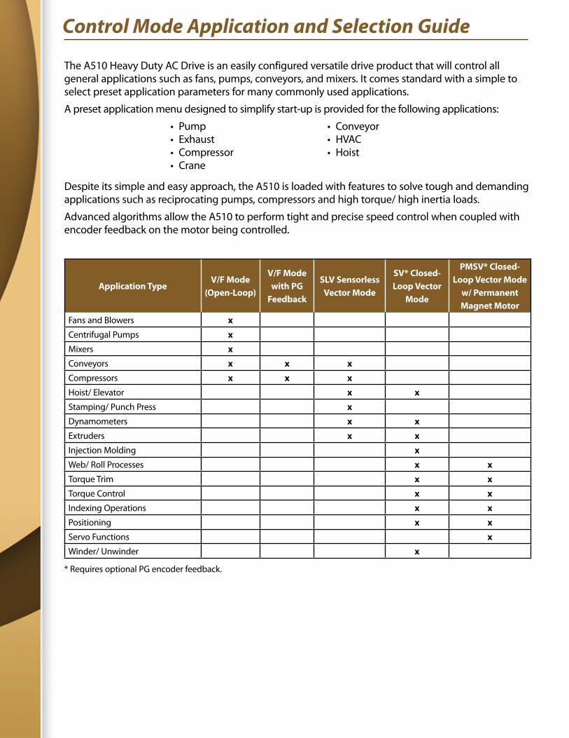
Control Mode Application and Selection Guide
The A510 Heavy Duty AC Drive is an easily configured versatile drive product that will control all general applications such as fans, pumps, conveyors, and mixers. It comes standard with a simple to select preset application parameters for many commonly used applications.
A preset application menu designed to simplify start-up is provided for the following applications:
Despite its simple and easy approach, the A510 is loaded with features to solve tough and demanding applications such as reciprocating pumps, compressors and high torque/ high inertia loads.
Advanced algorithms allow the A510 to perform tight and precise speed control when coupled with encoder feedback on the motor being controlled.
Application TypeV/F Mode
(Open-Loop)
V/F Mode with PG
Feedback
SLV Sensorless Vector Mode
SV* Closed-Loop Vector
Mode
PMSV* Closed-Loop Vector Mode
w/ Permanent Magnet Motor
Fans and Blowers x
Centrifugal Pumps x
Mixers x
Conveyors x x x
Compressors x x x
Hoist/ Elevator x x
Stamping/ Punch Press x
Dynamometers x x
Extruders x x
Injection Molding x
Web/ Roll Processes x x
Torque Trim x x
Torque Control x x
Indexing Operations x x
Positioning x x
Servo Functions x
Winder/ Unwinder x
* Requires optional PG encoder feedback.
• Pump• Exhaust• Compressor• Crane
• Conveyor• HVAC• Hoist
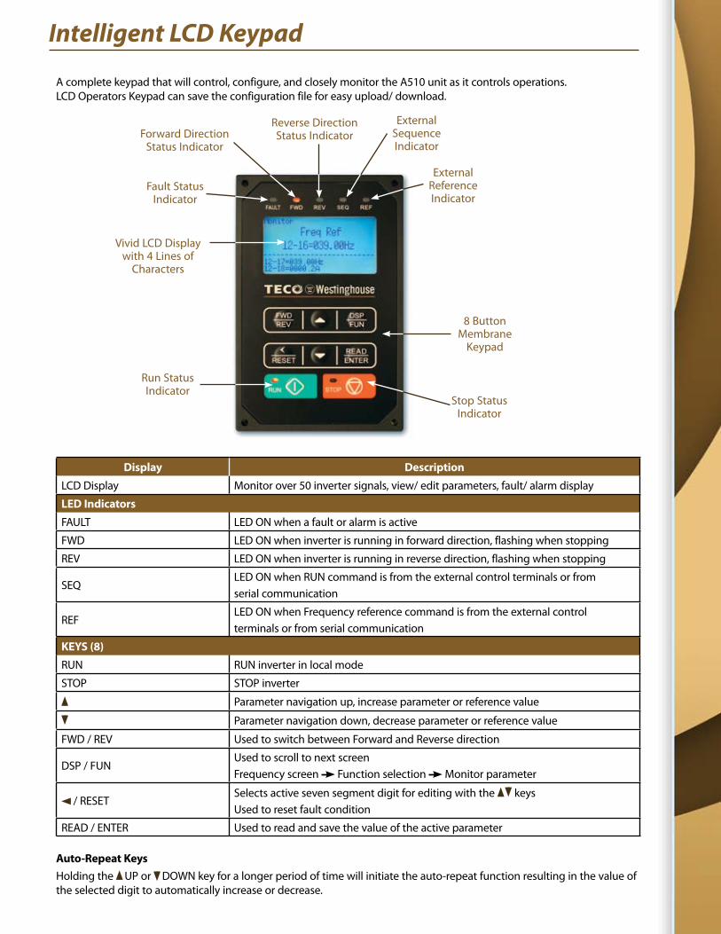
Display Description
LCD Display Monitor over 50 inverter signals, view/ edit parameters, fault/ alarm display
LED Indicators
FAULT LED ON when a fault or alarm is active
FWD LED ON when inverter is running in forward direction, flashing when stopping
REV LED ON when inverter is running in reverse direction, flashing when stopping
SEQLED ON when RUN command is from the external control terminals or from serial communication
REFLED ON when Frequency reference command is from the external control terminals or from serial communication
KEYS (8)
RUN RUN inverter in local mode
STOP STOP inverter
Parameter navigation up, increase parameter or reference value
Parameter navigation down, decrease parameter or reference value
FWD / REV Used to switch between Forward and Reverse direction
DSP / FUNUsed to scroll to next screen Frequency screen Function selection Monitor parameter
/ RESETSelects active seven segment digit for editing with the keys Used to reset fault condition
READ / ENTER Used to read and save the value of the active parameter
Auto-Repeat KeysHolding the UP or DOWN key for a longer period of time will initiate the auto-repeat function resulting in the value of the selected digit to automatically increase or decrease.
Intelligent LCD Keypad
Vivid LCD Displaywith 4 Lines of
Characters
ExternalReferenceIndicator
ExternalSequenceIndicator
Reverse DirectionStatus IndicatorForward Direction
Status Indicator
Fault StatusIndicator
Run StatusIndicator
Stop StatusIndicator
8 ButtonMembrane
Keypad
A complete keypad that will control, configure, and closely monitor the A510 unit as it controls operations. LCD Operators Keypad can save the configuration file for easy upload/ download.
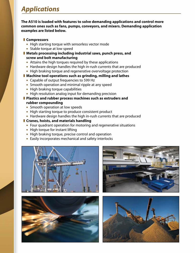
The A510 is loaded with features to solve demanding applications and control more common ones such as fans, pumps, conveyors, and mixers. Demanding application examples are listed below.
z Compressors l High starting torque with sensorless vector mode l Stable torque at low speed
z Metals processing including industrial saws, punch press, and screw and bolt manufacturing
l Attains the high torques required by these applications l Hardware design handles the high in-rush currents that are produced l High braking torque and regenerative overvoltage protection
z Machine tool operations such as grinding, milling and lathes l Capable of output frequencies to 599 Hz l Smooth operation and minimal ripple at any speed l High braking torque capabilities l High resolution analog input for demanding precision
z Plastics and rubber process machines such as extruders and rubber compounding
l Smooth operation at low speeds l High starting torque to produce consistent product l Hardware design handles the high in-rush currents that are produced
z Cranes, hoists, and materials handling l Four quadrant operation for motoring and regenerative situations l High torque for instant lifting l High braking torque, precise control and operation l Easily incorporates mechanical and safety interlocks
Applications
Features & Highlights
z Selectable Control Modes designed to cover almost all motor driven applications l V/F Mode with constant and variable torque settings l V/F Mode with PG encoder feedback to improve speed regulation l Sensorless Vector for more dynamic applications l Sensorless Vector with permanent magnet motors for more dynamic applications l Closed Loop Vector for the most demanding applications involving both speed and torque control 1000:1 Speed control range 5% Torque regulation l Closed Loop Vector with Permanent Magnet Motors for servo-type control l Sensorless vector control with dynamic control and rotational tuning z Attains high levels of torque l 200% Starting torque in sensorless vector modes l 200% Holding torque in closed-loop vector modes z Select matching application type for quick setting of parameter defaults z Advanced regenerative energy handling capabilities with overvoltage suppression l Reduce the need for costly braking resistor units z Extensive Monitoring and Display capabilities l Display over 40 different operating and status information variables including Input and output frequencies Output current and voltage Analog and digital I/O status PID related data Vector PID loop control information Motor operating data l Retains 4 most recent faults in a log Operating information at instant of occurrence of most recent fault z PLC functionality built-in to enhance application flexibility z Advanced tuning/ motor matching capabilities l Control induction or permanent magnet motors l 5th generation tuning algorithms for optimized vector control and motor coordination Dynamic tuning Static tuning z Pulse Width Modulation (PWM) technology that reduces motor noise z 32 Bit, 100 MHz processor for extremely fast response z Digital I/O l 8 configurable digital inputs 24V power on board Over 40 available selections per input Assign each input as a normally open or closed input Fast update time
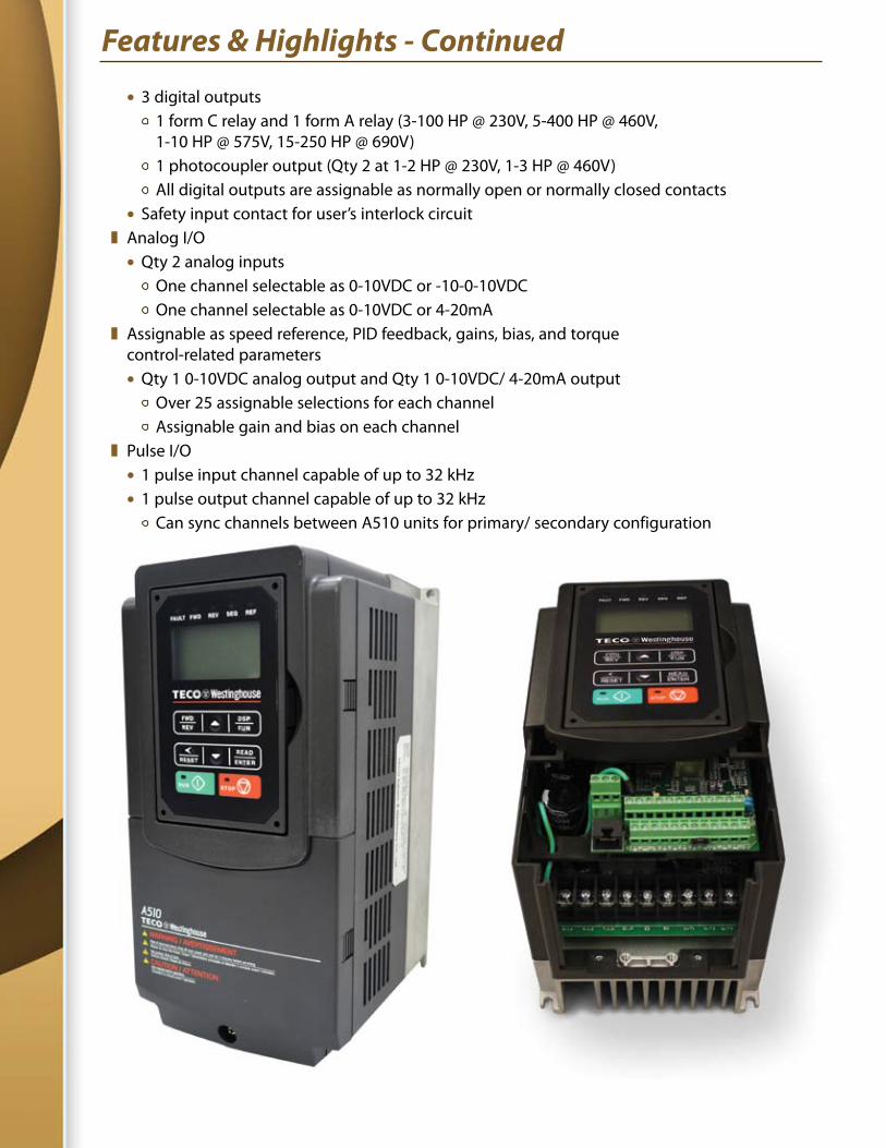
Features & Highlights - Continued
l 3 digital outputs 1 form C relay and 1 form A relay (3-100 HP @ 230V, 5-400 HP @ 460V, 1-10 HP @ 575V, 15-250 HP @ 690V) 1 photocoupler output (Qty 2 at 1-2 HP @ 230V, 1-3 HP @ 460V) All digital outputs are assignable as normally open or normally closed contacts l Safety input contact for user’s interlock circuit z Analog I/O l Qty 2 analog inputs One channel selectable as 0-10VDC or -10-0-10VDC One channel selectable as 0-10VDC or 4-20mA z Assignable as speed reference, PID feedback, gains, bias, and torque control-related parameters l Qty 1 0-10VDC analog output and Qty 1 0-10VDC/ 4-20mA output Over 25 assignable selections for each channel Assignable gain and bias on each channel z Pulse I/O l 1 pulse input channel capable of up to 32 kHz l 1 pulse output channel capable of up to 32 kHz Can sync channels between A510 units for primary/ secondary configuration
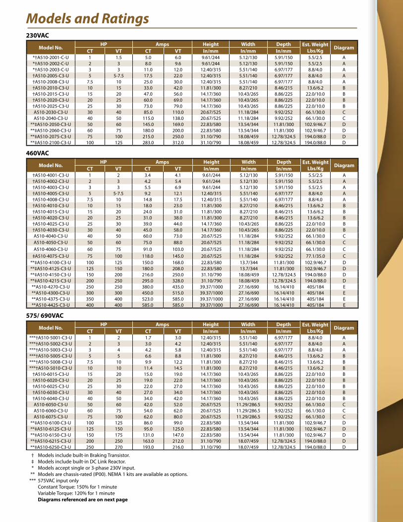
Models and Ratings230VAC
Model No.HP Amps Height Width Depth Est. Weight
Lbs/Kg DiagramCT VT CT VT In/mm In/mm In/mm
*†A510-2001-C-U 1 1.5 5.0 6.0 9.61/244 5.12/130 5.91/150 5.5/2.5 A*†A510-2002-C-U 2 3 8.0 9.6 9.61/244 5.12/130 5.91/150 5.5/2.5 A*†A510-2003-C-U 3 3 11.0 12.0 12.40/315 5.51/140 6.97/177 8.8/4.0 A†A510-2005-C3-U 5 5-7.5 17.5 22.0 12.40/315 5.51/140 6.97/177 8.8/4.0 A†A510-2008-C3-U 7.5 10 25.0 30.0 12.40/315 5.51/140 6.97/177 8.8/4.0 A†A510-2010-C3-U 10 15 33.0 42.0 11.81/300 8.27/210 8.46/215 13.6/6.2 B†A510-2015-C3-U 15 20 47.0 56.0 14.17/360 10.43/265 8.86/225 22.0/10.0 B†A510-2020-C3-U 20 25 60.0 69.0 14.17/360 10.43/265 8.86/225 22.0/10.0 B†A510-2025-C3-U 25 30 73.0 79.0 14.17/360 10.43/265 8.86/225 22.0/10.0 BA510-2030-C3-U 30 40 85.0 110.0 20.67/525 11.18/284 9.92/252 66.1/30.0 CA510-2040-C3-U 40 50 115.0 138.0 20.67/525 11.18/284 9.92/252 66.1/30.0 C
**‡A510-2050-C3-U 50 60 145.0 169.0 22.83/580 13.54/344 11.81/300 102.9/46.7 D**‡A510-2060-C3-U 60 75 180.0 200.0 22.83/580 13.54/344 11.81/300 102.9/46.7 D**‡A510-2075-C3-U 75 100 215.0 250.0 31.10/790 18.08/459 12.78/324.5 194.0/88.0 D**‡A510-2100-C3-U 100 125 283.0 312.0 31.10/790 18.08/459 12.78/324.5 194.0/88.0 D
460VAC
Model No.HP Amps Height Width Depth Est. Weight
Lbs/Kg DiagramCT VT CT VT In/mm In/mm In/mm
†A510-4001-C3-U 1 2 3.4 4.1 9.61/244 5.12/130 5.91/150 5.5/2.5 A†A510-4002-C3-U 2 3 4.2 5.4 9.61/244 5.12/130 5.91/150 5.5/2.5 A†A510-4003-C3-U 3 3 5.5 6.9 9.61/244 5.12/130 5.91/150 5.5/2.5 A†A510-4005-C3-U 5 5-7.5 9.2 12.1 12.40/315 5.51/140 6.97/177 8.8/4.0 A†A510-4008-C3-U 7.5 10 14.8 17.5 12.40/315 5.51/140 6.97/177 8.8/4.0 A†A510-4010-C3-U 10 15 18.0 23.0 11.81/300 8.27/210 8.46/215 13.6/6.2 B†A510-4015-C3-U 15 20 24.0 31.0 11.81/300 8.27/210 8.46/215 13.6/6.2 B†A510-4020-C3-U 20 25 31.0 38.0 11.81/300 8.27/210 8.46/215 13.6/6.2 B†A510-4025-C3-U 25 30 39.0 44.0 14.17/360 10.43/265 8.86/225 22.0/10.0 B†A510-4030-C3-U 30 40 45.0 58.0 14.17/360 10.43/265 8.86/225 22.0/10.0 BA510-4040-C3-U 40 50 60.0 73.0 20.67/525 11.18/284 9.92/252 66.1/30.0 CA510-4050-C3-U 50 60 75.0 88.0 20.67/525 11.18/284 9.92/252 66.1/30.0 CA510-4060-C3-U 60 75 91.0 103.0 20.67/525 11.18/284 9.92/252 66.1/30.0 C
‡A510-4075-C3-U 75 100 118.0 145.0 20.67/525 11.18/284 9.92/252 77.1/35.0 C**‡A510-4100-C3-U 100 125 150.0 168.0 22.83/580 13.7/344 11.81/300 102.9/46.7 D**‡A510-4125-C3-U 125 150 180.0 208.0 22.83/580 13.7/344 11.81/300 102.9/46.7 D**‡A510-4150-C3-U 150 200 216.0 250.0 31.10/790 18.08/459 12.78/324.5 194.0/88.0 D**‡A510-4215-C3-U 200 250 295.0 328.0 31.10/790 18.08/459 12.78/324.5 194.0/88.0 D**A510-4270-C3-U 250 250 380.0 435.0 39.37/1000 27.16/690 16.14/410 405/184 E**A510-4300-C3-U 300 300 450.0 515.0 39.37/1000 27.16/690 16.14/410 405/184 E**A510-4375-C3-U 350 400 523.0 585.0 39.37/1000 27.16/690 16.14/410 405/184 E**A510-4425-C3-U 400 400 585.0 585.0 39.37/1000 27.16/690 16.14/410 405/184 E
575/ 690VAC
Model No.HP Amps Height Width Depth Est. Weight
Lbs/Kg DiagramCT VT CT VT In/mm In/mm In/mm
***†A510-5001-C3-U 1 2 1.7 3.0 12.40/315 5.51/140 6.97/177 8.8/4.0 A***†A510-5002-C3-U 2 3 3.0 4.2 12.40/315 5.51/140 6.97/177 8.8/4.0 A***†A510-5003-C3-U 3 4 4.2 5.8 12.40/315 5.51/140 6.97/177 8.8/4.0 A***†A510-5005-C3-U 5 5 6.6 8.8 11.81/300 8.27/210 8.46/215 13.6/6.2 B***†A510-5008-C3-U 7.5 10 9.9 12.2 11.81/300 8.27/210 8.46/215 13.6/6.2 B***†A510-5010-C3-U 10 10 11.4 14.5 11.81/300 8.27/210 8.46/215 13.6/6.2 B
†A510-6015-C3-U 15 20 15.0 19.0 14.17/360 10.43/265 8.86/225 22.0/10.0 B†A510-6020-C3-U 20 25 19.0 22.0 14.17/360 10.43/265 8.86/225 22.0/10.0 B†A510-6025-C3-U 25 30 22.0 27.0 14.17/360 10.43/265 8.86/225 22.0/10.0 B†A510-6030-C3-U 30 40 27.0 34.0 14.17/360 10.43/265 8.86/225 22.0/10.0 B†A510-6040-C3-U 40 50 34.0 42.0 14.17/360 10.43/265 8.86/225 22.0/10.0 BA510-6050-C3-U 50 60 42.0 52.0 20.67/525 11.29/286.5 9.92/252 66.1/30.0 CA510-6060-C3-U 60 75 54.0 62.0 20.67/525 11.29/286.5 9.92/252 66.1/30.0 CA510-6075-C3-U 75 100 62.0 80.0 20.67/525 11.29/286.5 9.92/252 66.1/30.0 C
**‡A510-6100-C3-U 100 125 86.0 99.0 22.83/580 13.54/344 11.81/300 102.9/46.7 D**‡A510-6125-C3-U 125 150 95.0 125.0 22.83/580 13.54/344 11.81/300 102.9/46.7 D**‡A510-6150-C3-U 150 175 131.0 147.0 22.83/580 13.54/344 11.81/300 102.9/46.7 D**‡A510-6215-C3-U 200 250 163.0 212.0 31.10/790 18.07/459 12.78/324.5 194.0/88.0 D**‡A510-6250-C3-U 250 270 193.0 216.0 31.10/790 18.07/459 12.78/324.5 194.0/88.0 D
† Models include built-in Braking Transistor. ‡ Models include built-in DC Link Reactor. * Models accept single or 3-phase 230V input. ** Models are chassis-rated (IP00). NEMA 1 kits are available as options. *** 575VAC input only Constant Torque: 150% for 1 minute Variable Torque: 120% for 1 minute Diagrams referenced are on next page
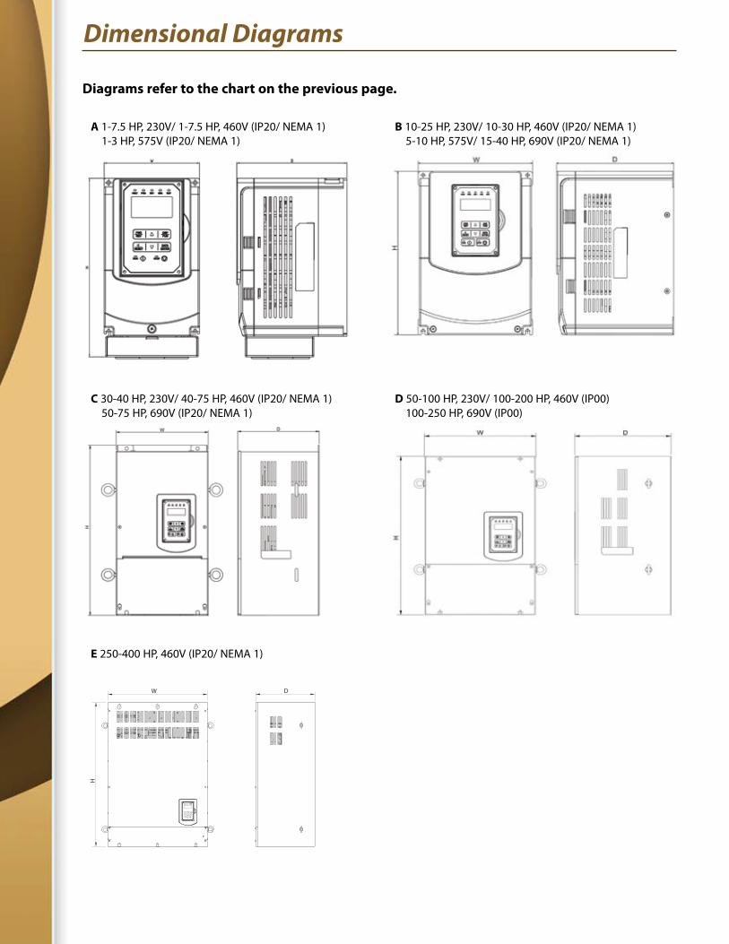
Dimensional Diagrams
A 1-7.5 HP, 230V/ 1-7.5 HP, 460V (IP20/ NEMA 1) 1-3 HP, 575V (IP20/ NEMA 1)
C 30-40 HP, 230V/ 40-75 HP, 460V (IP20/ NEMA 1) 50-75 HP, 690V (IP20/ NEMA 1)
E 250-400 HP, 460V (IP20/ NEMA 1)
B 10-25 HP, 230V/ 10-30 HP, 460V (IP20/ NEMA 1) 5-10 HP, 575V/ 15-40 HP, 690V (IP20/ NEMA 1)
D 50-100 HP, 230V/ 100-200 HP, 460V (IP00) 100-250 HP, 690V (IP00)
Diagrams refer to the chart on the previous page.
W
H
D
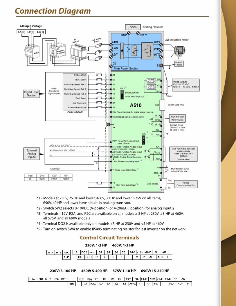
Connection Diagram
*1 - Models at 230V, 25 HP and lower; 460V, 30 HP and lower; 575V on all items; 690V, 40 HP and lower have a built-in braking transistor.*2 - Switch SW2 selects 0-10VDC (V-position) or 4-20mA (I position) for analog input 2*3 - Terminals - 12V, R2A, and R2C are available on all models ≥ 3 HP at 230V, ≥5 HP at 460V, all 575V, and all 690V models*4 - Terminal DO2 is available only on models <3 HP at 230V and <5 HP at 460V*5 - Turn on switch SW4 to enable RS485 terminating resistor for last inverter on the network.
Control Circuit Terminals230V: 1-2 HP 460V: 1-3 HP
230V: 3-100 HP 460V: 5-400 HP 575V:1-10 HP 690V: 15-250 HP
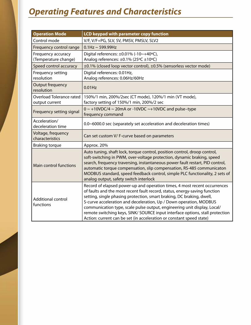
Operating Features and Characteristics
Operation Mode LCD keypad with parameter copy functionControl mode V/F, V/F+PG, SLV, SV, PMSV, PMSLV, SLV2Frequency control range 0.1Hz ~ 599.99HzFrequency accuracy (Temperature change)
Digital references: ±0.01% (-10~+40ºC), Analog references: ±0.1% (25ºC ±10ºC)
Speed control accuracy ±0.1% (closed loop vector control), ±0.5% (sensorless vector mode)Frequency setting resolution
Digital references: 0.01Hz, Analog references: 0.06Hz/60Hz
Output frequency resolution 0.01Hz
Overload Tolerance rated output current
150%/1 min, 200%/2sec (CT mode), 120%/1 min (VT mode), factory setting of 150%/1 min, 200%/2 sec
Frequency setting signal 0 ~ +10VDC/4 ~ 20mA or -10VDC ~+10VDC and pulse–type frequency command
Acceleration/ deceleration time 0.0~6000.0 sec (separately set acceleration and deceleration times)
Voltage, frequency characteristics Can set custom V/ F-curve based on parameters
Braking torque Approx. 20%
Main control functions
Auto tuning, shaft lock, torque control, position control, droop control, soft-switching in PWM, over-voltage protection, dynamic braking, speed search, frequency traversing, instantaneous power fault restart, PID control, automatic torque compensation, slip compensation, RS-485 communicaton MODBUS standard, speed feedback control, simple PLC functionality, 2 sets of analog output, safety switch interlock
Additional control functions
Record of elapsed power-up and operation times, 4 most recent occurrences of faults and the most recent fault record, status, energy-saving function setting, single phasing protection, smart braking, DC braking, dwell, S-curve acceleration and deceleration, Up / Down operation, MODBUS communication type, scale pulse output, engineering unit display, Local/ remote switching keys, SINK/ SOURCE input interface options, stall protection Action: current can be set (in acceleration or constant speed state)
Operating Features and Characteristics - Continued
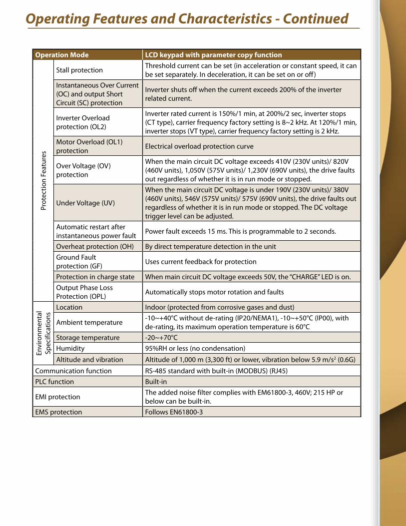
Operation Mode LCD keypad with parameter copy function
Prot
ectio
n Fe
atur
es
Stall protection Threshold current can be set (in acceleration or constant speed, it can be set separately. In deceleration, it can be set on or off )
Instantaneous Over Current (OC) and output Short Circuit (SC) protection
Inverter shuts off when the current exceeds 200% of the inverter related current.
Inverter Overload protection (OL2)
Inverter rated current is 150%/1 min, at 200%/2 sec, inverter stops (CT type), carrier frequency factory setting is 8~2 kHz. At 120%/1 min, inverter stops (VT type), carrier frequency factory setting is 2 kHz.
Motor Overload (OL1) protection Electrical overload protection curve
Over Voltage (OV) protection
When the main circuit DC voltage exceeds 410V (230V units)/ 820V (460V units), 1,050V (575V units)/ 1,230V (690V units), the drive faults out regardless of whether it is in run mode or stopped.
Under Voltage (UV)
When the main circuit DC voltage is under 190V (230V units)/ 380V (460V units), 546V (575V units)/ 575V (690V units), the drive faults out regardless of whether it is in run mode or stopped. The DC voltage trigger level can be adjusted.
Automatic restart after instantaneous power fault Power fault exceeds 15 ms. This is programmable to 2 seconds.
Overheat protection (OH) By direct temperature detection in the unitGround Fault protection (GF) Uses current feedback for protection
Protection in charge state When main circuit DC voltage exceeds 50V, the “CHARGE” LED is on.Output Phase Loss Protection (OPL) Automatically stops motor rotation and faults
Envi
ronm
enta
lSp
ecifi
catio
ns
Location Indoor (protected from corrosive gases and dust)
Ambient temperature -10~+40°C without de-rating (IP20/NEMA1), -10~+50°C (IP00), with de-rating, its maximum operation temperature is 60°C
Storage temperature -20~+70°CHumidity 95%RH or less (no condensation)
Altitude and vibration Altitude of 1,000 m (3,300 ft) or lower, vibration below 5.9 m/s2 (0.6G)
Communication function RS-485 standard with built-in (MODBUS) (RJ45)PLC function Built-in
EMI protection The added noise filter complies with EM61800-3, 460V; 215 HP or below can be built-in.
EMS protection Follows EN61800-3
Protection Features
z ASIC designed to protect transistor modules from impact of sudden or rapidly changing current
z EMC filters are available to all 460VAC rated models. Please consult factory.
z Regenerative energy control and over-voltage prevention
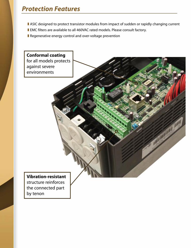
Vibration-resistant structure reinforces the connected part by tenon
Conformal coating for all models protects against severe environments
Programmable Logic Control (PLC) Capabilities
Applications with more demanding or complex requirements or restrictions on operation can be met with simple PLC functions used directly in the drive unit. For example, the application may be triggered by special operation sequencing or multiple independent events. Another possibility for the PLC functions is a system with permissives that cannot be adequately incorporated directly through the I/O alone.
The PLC function features many types of instruction blocks that will build a ladder logic program.
z Software relay functions
l Input contacts
l Output coils
l Internal software coils
l Normally open, normally closed, and edge-triggered contacts
z Numerical function blocks
l Counters (count up or count down to preset value)
l On-delay, off-delay, and on-off interval timing
l Analog comparator to trigger an event when an analog input or internal numerical value is above, below, or within range of a set value
l Operation control functions to run the driven motor
l Add/ subtract and multiply/ divide blocks for signal scaling and conditioning
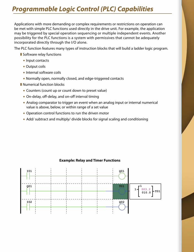
Example: Relay and Timer Functions
I01 D Q01
I02 d Q02
I01 Q01
Q01 T01
I02 Q02
T0111
010.0003.2
Options and Accessories
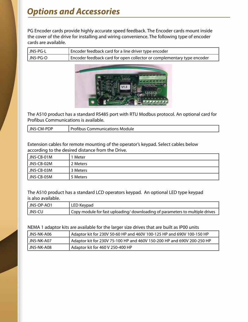
PG Encoder cards provide highly accurate speed feedback. The Encoder cards mount inside the cover of the drive for installing and wiring convenience. The following type of encoder cards are available.
JN5-PG-L Encoder feedback card for a line driver type encoderJN5-PG-O Encoder feedback card for open collector or complementary type encoder
The A510 product has a standard RS485 port with RTU Modbus protocol. An optional card for Profibus Communications is available.
JN5-CM-PDP Profibus Communications Module
Extension cables for remote mounting of the operator’s keypad. Select cables below according to the desired distance from the Drive.JN5-CB-01M 1 MeterJN5-CB-02M 2 MetersJN5-CB-03M 3 MetersJN5-CB-05M 5 Meters
The A510 product has a standard LCD operators keypad. An optional LED type keypad is also available. JN5-OP-AO1 LED KeypadJN5-CU Copy module for fast uploading/ downloading of parameters to multiple drives
NEMA 1 adaptor kits are available for the larger size drives that are built as IP00 unitsJN5-NK-A06 Adaptor kit for 230V 50-60 HP and 460V 100-125 HP and 690V 100-150 HPJN5-NK-A07 Adaptor kit for 230V 75-100 HP and 460V 150-200 HP and 690V 200-250 HPJN5-NK-A08 Adaptor kit for 460 V 250-400 HP
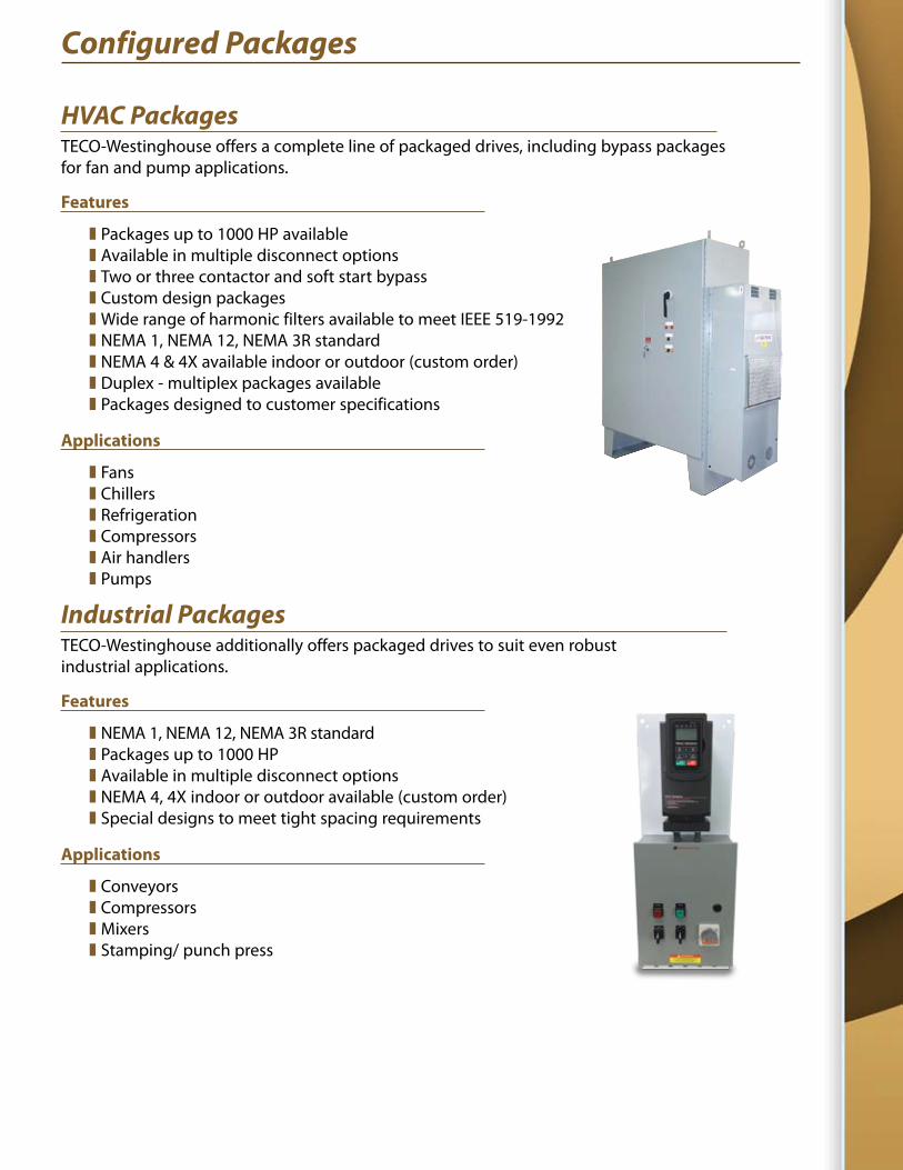
Configured Packages
HVAC Packages TECO-Westinghouse offers a complete line of packaged drives, including bypass packages for fan and pump applications.
Features
z Packages up to 1000 HP available z Available in multiple disconnect options z Two or three contactor and soft start bypass z Custom design packages z Wide range of harmonic filters available to meet IEEE 519-1992 z NEMA 1, NEMA 12, NEMA 3R standard z NEMA 4 & 4X available indoor or outdoor (custom order) z Duplex - multiplex packages available z Packages designed to customer specifications
Applications
z Fans z Chillers z Refrigeration z Compressors z Air handlers z Pumps
Industrial Packages TECO-Westinghouse additionally offers packaged drives to suit even robust industrial applications.
Features
z NEMA 1, NEMA 12, NEMA 3R standard z Packages up to 1000 HP z Available in multiple disconnect options z NEMA 4, 4X indoor or outdoor available (custom order) z Special designs to meet tight spacing requirements
Applications
z Conveyors z Compressors z Mixers z Stamping/ punch press
D-A510 5-18
TECO-Westinghouse Motor Company offers an extensive line of Variable Speed Drives and Soft Starters for your motor control applications.
We also offer a wide variety of motors that are matched with the Drives and Soft Starters including Vertical Hollow Shaft, Rolled Steel, and NEMA Premium Efficient motors.
From “in stock” controls to engineered systems, we can provide you the right control solution including an extensive line of TECO-Westinghouse AC Motors.
5100 N. IH-35Round Rock, Texas 786811-800-279-4007
www.tecowestinghouse.com
Recommended