December, 2013 Page 1 of 37
By: Nu-Air Ventilation Systems Inc.
Heat Your Home
Cool Your Home
Ventilate Your Home
All With One Unit
OPERATING MANUAL EN4X, EN7X, AND EN9X SERIES
December, 2013 Page 2 of 37
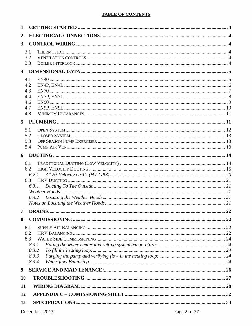
TABLE OF CONTENTS
GETTING STARTED ......................................................................................................................... 4 1
ELECTRICAL CONNECTIONS ....................................................................................................... 4 2
CONTROL WIRING ........................................................................................................................... 4 3
3.1 THERMOSTAT .................................................................................................................................... 4 3.2 VENTILATION CONTROLS .................................................................................................................. 4
3.3 BOILER INTERLOCK ........................................................................................................................... 4
DIMENSIONAL DATA ....................................................................................................................... 5 4
4.1 EN40 ................................................................................................................................................ 5 4.2 EN4P, EN4L .................................................................................................................................... 6 4.3 EN70 ................................................................................................................................................ 7
4.4 EN7P, EN7L .................................................................................................................................... 8
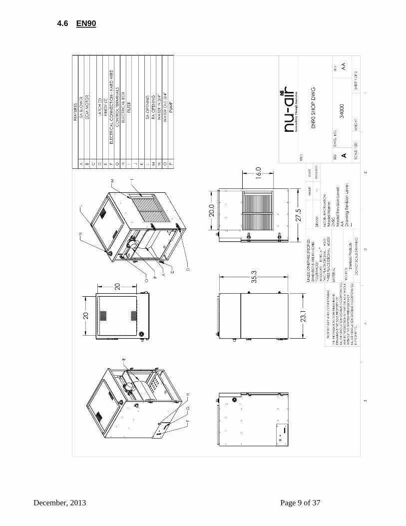
4.6 EN90 ................................................................................................................................................ 9
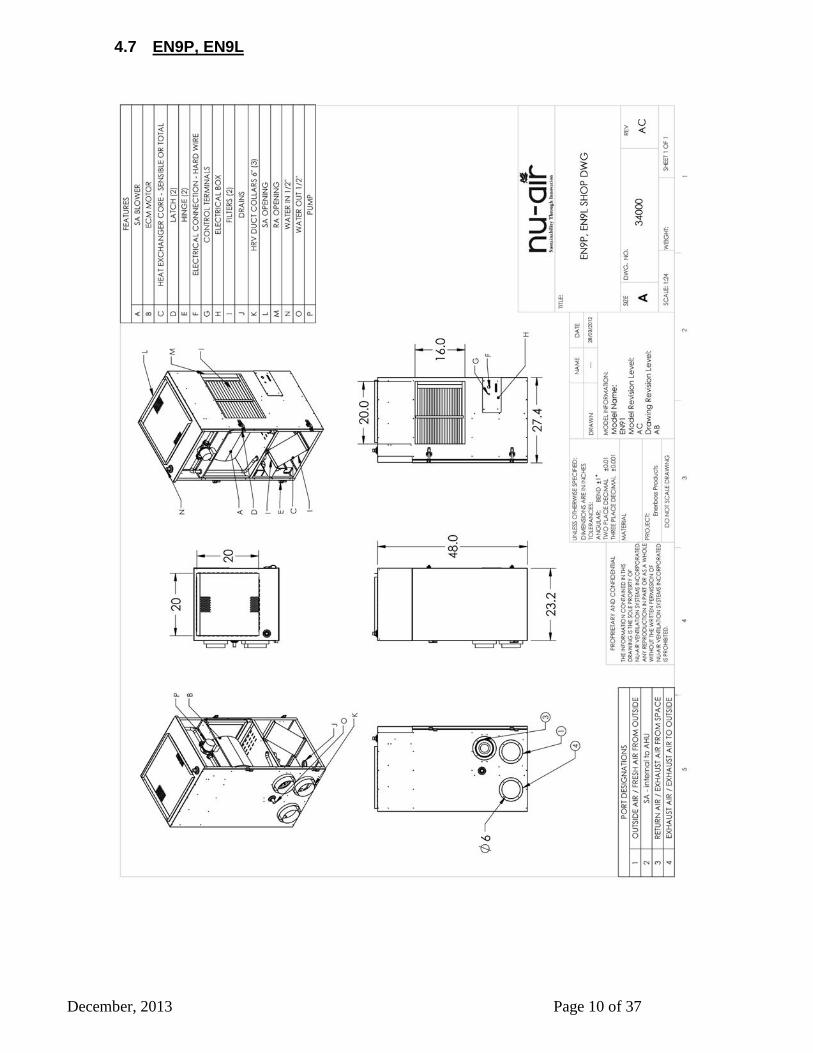
4.7 EN9P, EN9L .................................................................................................................................. 10 4.8 MINIMUM CLEARANCES ................................................................................................................. 11
PLUMBING ........................................................................................................................................ 11 5
5.1 OPEN SYSTEM ................................................................................................................................. 12
5.2 CLOSED SYSTEM ............................................................................................................................. 13 5.3 OFF SEASON PUMP EXERCISER ....................................................................................................... 13
5.4 PUMP AIR VENT .............................................................................................................................. 13
DUCTING ........................................................................................................................................... 14 6
6.1 TRADITIONAL DUCTING (LOW VELOCITY) ..................................................................................... 14
6.2 HIGH VELOCITY DUCTING .............................................................................................................. 15
3” Hi-Velocity Grills (HV-GR3) ............................................................................................. 20 6.2.1
6.3 HRV DUCTING ............................................................................................................................... 21 Ducting To The Outside .......................................................................................................... 21 6.3.1
Weather Hoods ..................................................................................................................................... 21 Locating the Weather Hoods ................................................................................................... 21 6.3.2
Notes on Locating the Weather Hoods ................................................................................................. 21
DRAINS ............................................................................................................................................... 22 7
COMMISSIONING ........................................................................................................................... 22 8
8.1 SUPPLY AIR BALANCING ................................................................................................................ 22 8.2 HRV BALANCING ........................................................................................................................... 22 8.3 WATER SIDE COMMISSIONING ........................................................................................................ 24
Filling the water heater and setting system temperature: ...................................................... 24 8.3.1
To fill the heating loop: ........................................................................................................... 24 8.3.2
Purging the pump and verifying flow in the heating loop: ..................................................... 24 8.3.3
Water flow Balancing: ............................................................................................................ 24 8.3.4
SERVICE AND MAINTENANCE: .................................................................................................. 26 9
TROUBLESHOOTING ................................................................................................................. 27 10
WIRING DIAGRAM ...................................................................................................................... 28 11
APPENDIX C – COMISSIONING SHEET ................................................................................. 32 12
SPECIFICATIONS ......................................................................................................................... 33 13

December, 2013 Page 3 of 37
13.4 EN4X .......................................................................................................................................... 33 13.5 EN7X .......................................................................................................................................... 33 13.6 EN9X .......................................................................................................................................... 34
ECM SPEED SETTINGS .............................................................................................................. 35 14
14.4 EN4 ............................................................................................................................................. 35 14.5 EN7 ............................................................................................................................................. 35 14.6 EN9 ............................................................................................................................................. 36
WARRANTY ................................................................................................................................... 37 15

December, 2013 Page 4 of 37
GETTING STARTED 1
The unit is shipped complete with the following:
1. The air-handler HRV module
2. Circulating pump
3. Check valve
4. Filters
5. HRV drain kit
Additional items required which are field installed include: plumbing fittings and valves such as an air
purge valve, anti-scald valve, shut off valve, gate valves, pipe insulation and drain valves. Also required
are duct fittings, a thermostat, a de-humidistat and other accessories such as grills and wire.
Note: When locating/placing the Enerboss, ensure there is a minimum clearance of 8 inches below to
allow for drain pipe connections. This can be accomplished by way of stand (Part # Ener Stand) or
blocks.
ELECTRICAL CONNECTIONS 2
A single point, hard-wired electrical connection requiring 115 VAC service and a dedicated 15 amp
fused circuit (20 Amp for EN9X series, 1 hp).
CONTROL WIRING 3
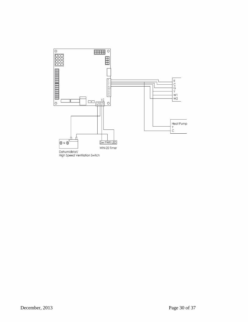
3.1 Thermostat
A heat/cool thermostat with fan switch connects to J7
R, G, Y, W1. C is 24V common. W2, X1,X2,X3,X4
are not used.
3.2 Ventilation controls
A two wire dehumidistat and/or mechanical timers
connect to J85&3 (24V and Humidity) for automatic
high speed ventilation. Nu-Air’s WIN20 push button
connects to J8 1,2&5.
3.3 Boiler interlock
J6 1&2 labeled relay provide dry contact switch closure whenever there is a call for heat from the
thermostat. Conect these to the boilers thermostat terminals.

December, 2013 Page 5 of 37
DIMENSIONAL DATA 4
4.1 EN40
December, 2013 Page 6 of 37
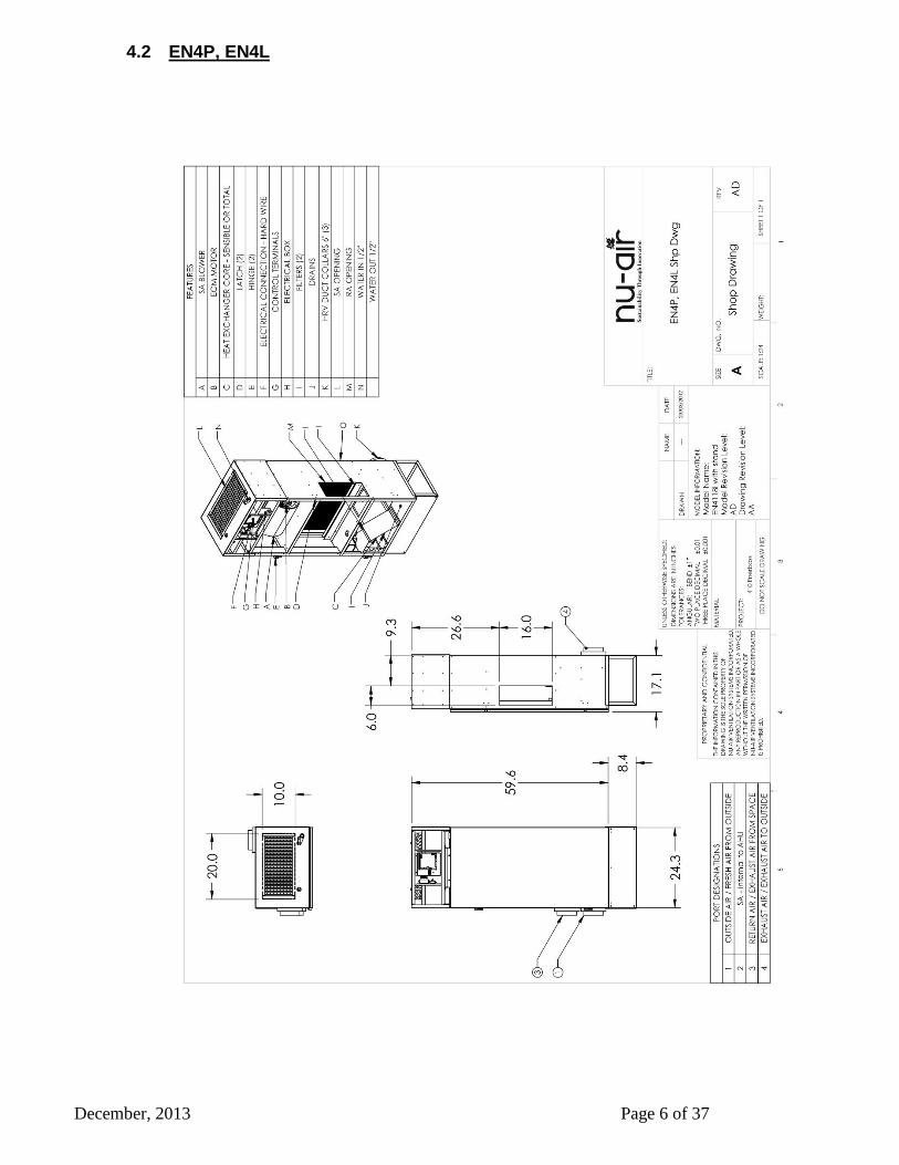
4.2 EN4P, EN4L
December, 2013 Page 7 of 37
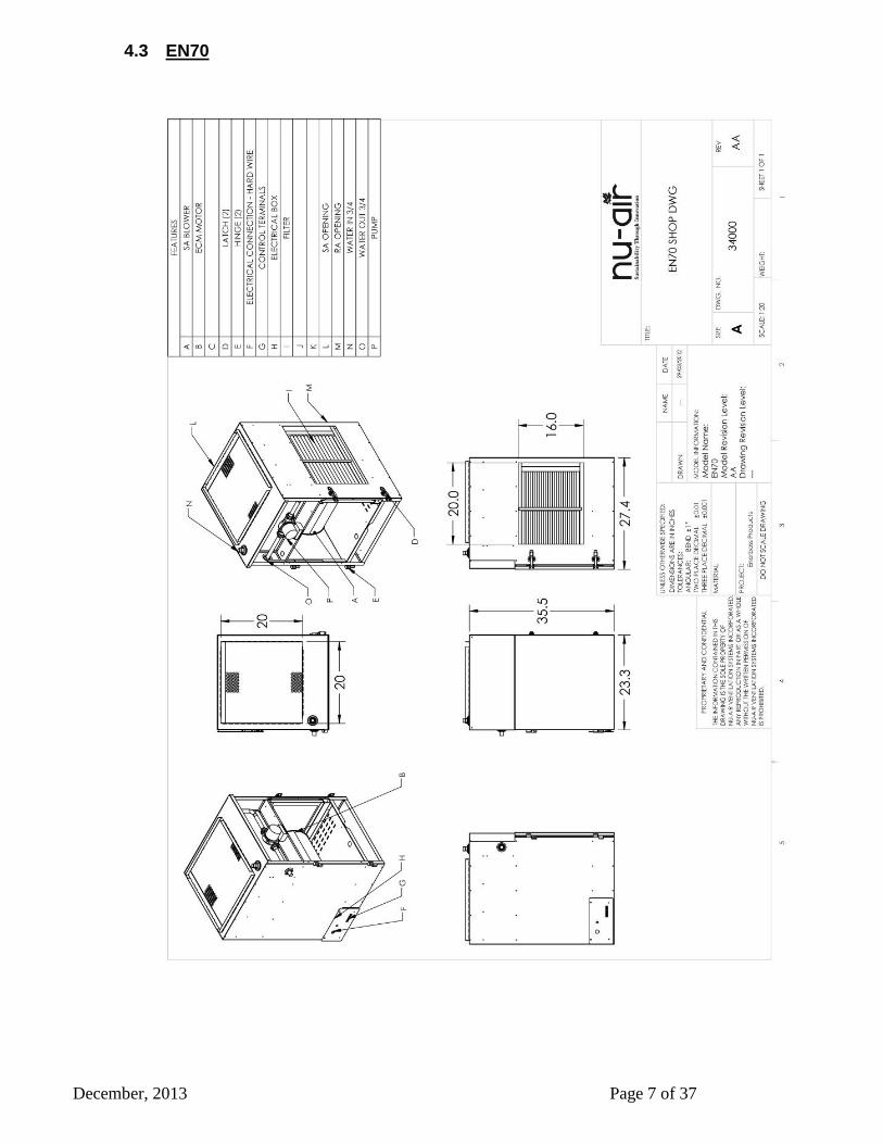
4.3 EN70
December, 2013 Page 8 of 37
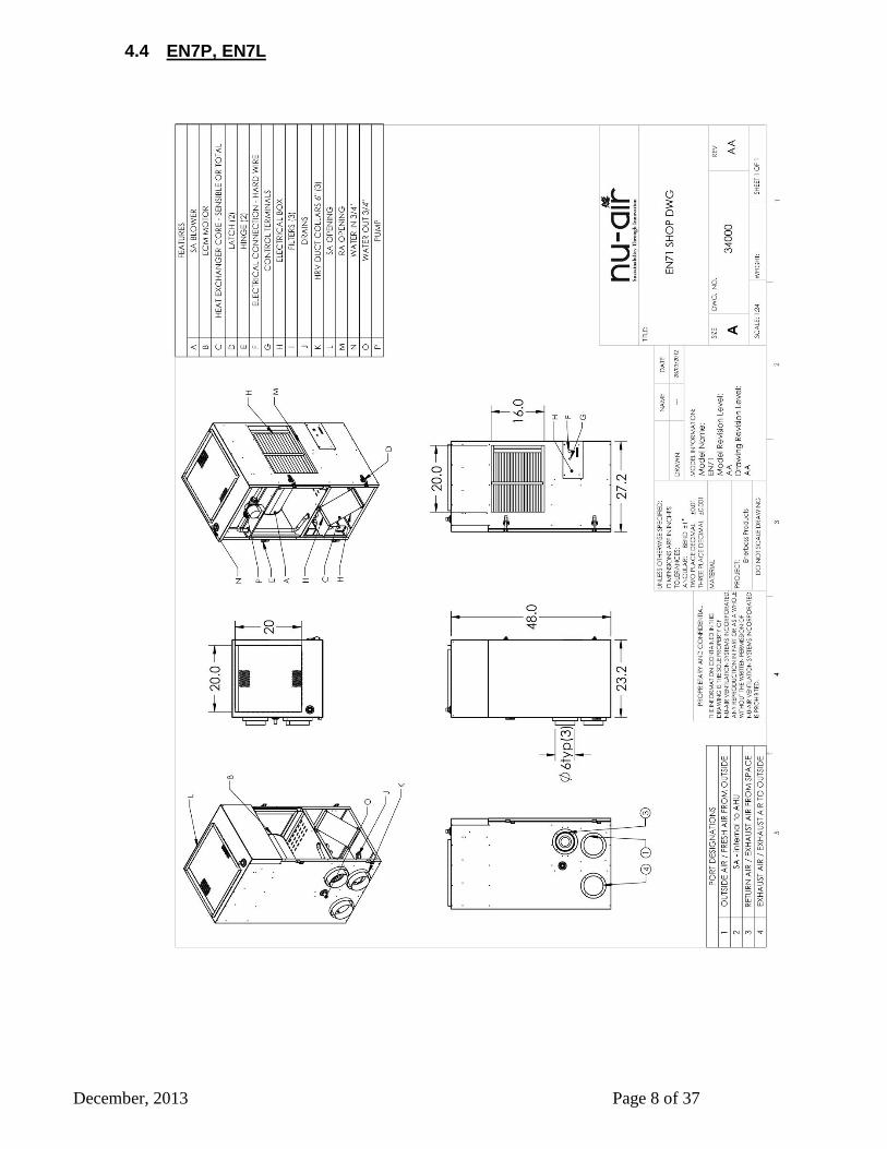
4.4 EN7P, EN7L
December, 2013 Page 9 of 37
4.6 EN90
December, 2013 Page 10 of 37
4.7 EN9P, EN9L
December, 2013 Page 11 of 37
4.8 Minimum Clearances
Model Front Left Right Back
EN40 24 12 24 0
EN4P,L 24 12 24 0
EN70 24 12 24 0
EN7P,L 24 12 24 0
EN90 24 12 24 0
EN9P,L 24 12 24 0
PLUMBING 5
All plumbing between components is typically done with 3/4" copper pipe and appropriate fittings. All
interconnecting piping is to be insulated.
System Types:
a) An Open System uses hot water from the residential hot water heater to supply both domestic hot
water and hot water to the Enerboss for space heat. See schematic on next page. Well systems
that incorporate a pressure tank are normally open systems.
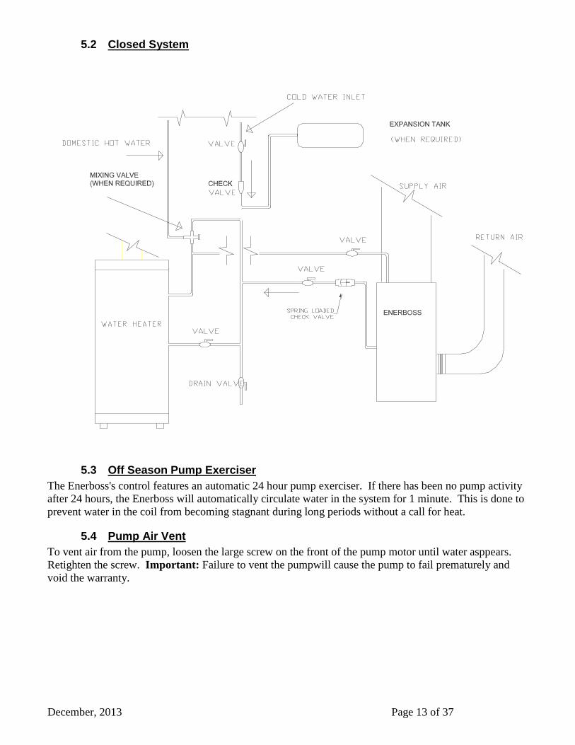
b) A system becomes closed when a backflow prevention valve or check valve is installed in the cold
water pipe upstream of the water heater. The backflow prevention valve does not allow pressure
created by the heated water to be relieved into the cold water system. Therefore an expansion tank
must be installed. Local codes may require this type of system.
The spring loaded check valve (supplied) must be installed on the return water line close to the
Enerboss. Ensure flow arrow points to tank or boiler.
An air purge valve should be installed at the high point in the supply line close to the Enerboss.

December, 2013 Page 12 of 37
5.1 Open System
December, 2013 Page 13 of 37
5.2 Closed System
5.3 Off Season Pump Exerciser
The Enerboss's control features an automatic 24 hour pump exerciser. If there has been no pump activity
after 24 hours, the Enerboss will automatically circulate water in the system for 1 minute. This is done to
prevent water in the coil from becoming stagnant during long periods without a call for heat.
5.4 Pump Air Vent
To vent air from the pump, loosen the large screw on the front of the pump motor until water asppears.
Retighten the screw. Important: Failure to vent the pumpwill cause the pump to fail prematurely and
void the warranty.

December, 2013 Page 14 of 37
(6" DIA INSULATED)EXHAUST AIR FROM SPACE
22 x 22 DEEP
SUPPLY AIR
18X 20
RETURN AIR
DAMPER
FRESH AIR FROM OUTSIDE 6"
EXHAUST AIR TO OUTSIDE
(BEHIND, NOT SHOWN)
(6" DIA INSULATED)
DUCTING 6
Air Handler
The Enerboss distributes heating, cooling and ventilation air through a 22” x 21” (500, 700, and 900
series) or 20”x 10” (400 series) rectangular plenum in an up-blast configuration. Return air enters the
unit through a 16” x 20” (500, 700, and 900 series) or 16”x6” (400 series) rectangular duct opening
located on the side. Proper sizing of the return air duct is critical to unit performance (see table
below for return air duct sizing). For Models with integral slab cooling coils turning vanes in the last
return bend are recommended for optimum
performance.
NOTE: Units with HRV or integrated cooling
coil must be installed on a minimum 8” stand or
blocking to allow for condensate drainage and
easy access to connections from below the unit.
6.1 Traditional Ducting (Low
Velocity)
Good engineering practice should be followed
when designing a duct system. Nu-Air
recommends the use of HRAI's Residential Air
System Design Manual.
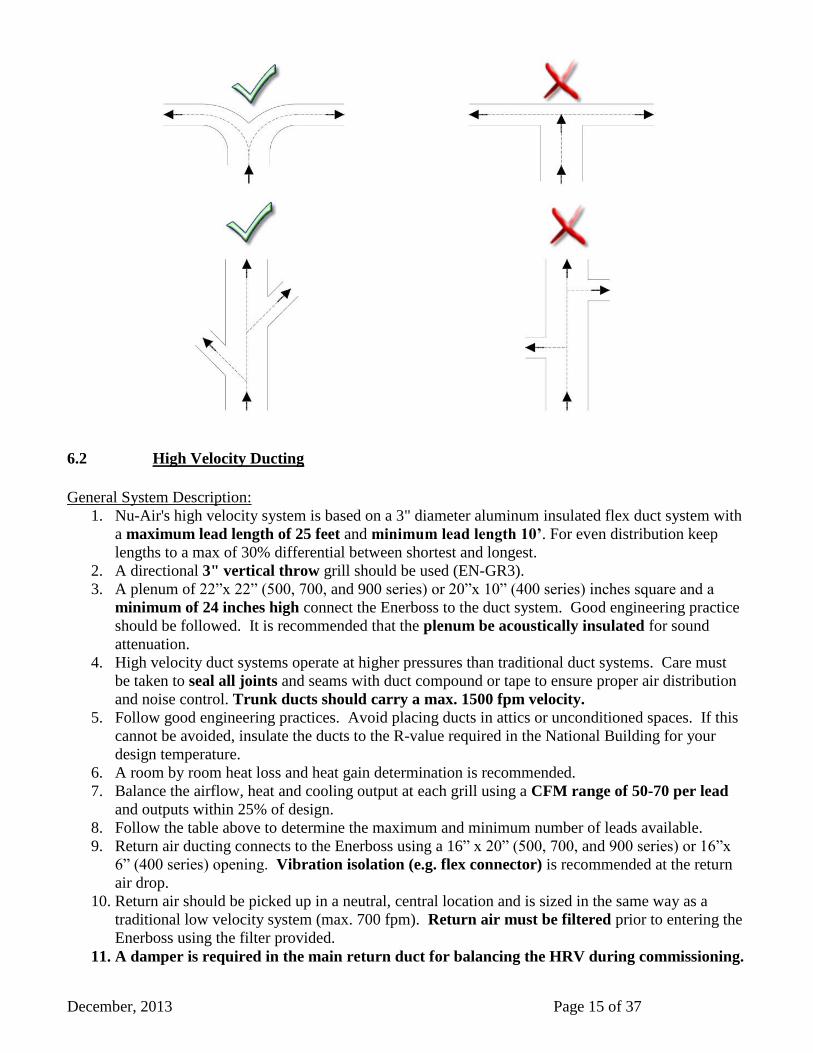
Low velocity ducting Do’s and Don’ts
NOTE: A damper is required in the main
return duct for balancing the HRV during
commissioning.
December, 2013 Page 15 of 37
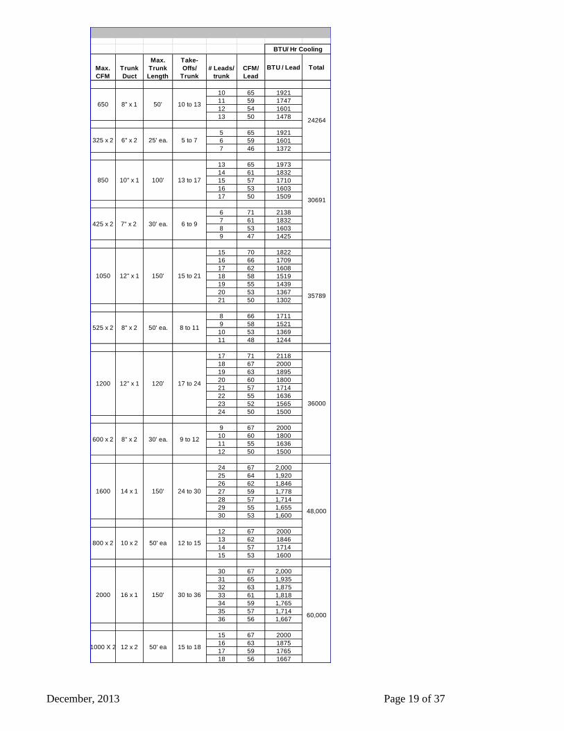
6.2 High Velocity Ducting
General System Description:
1. Nu-Air's high velocity system is based on a 3" diameter aluminum insulated flex duct system with
a maximum lead length of 25 feet and minimum lead length 10’. For even distribution keep
lengths to a max of 30% differential between shortest and longest.
2. A directional 3" vertical throw grill should be used (EN-GR3).
3. A plenum of 22”x 22” (500, 700, and 900 series) or 20”x 10” (400 series) inches square and a
minimum of 24 inches high connect the Enerboss to the duct system. Good engineering practice
should be followed. It is recommended that the plenum be acoustically insulated for sound
attenuation.
4. High velocity duct systems operate at higher pressures than traditional duct systems. Care must
be taken to seal all joints and seams with duct compound or tape to ensure proper air distribution
and noise control. Trunk ducts should carry a max. 1500 fpm velocity.
5. Follow good engineering practices. Avoid placing ducts in attics or unconditioned spaces. If this
cannot be avoided, insulate the ducts to the R-value required in the National Building for your
design temperature.
6. A room by room heat loss and heat gain determination is recommended.
7. Balance the airflow, heat and cooling output at each grill using a CFM range of 50-70 per lead
and outputs within 25% of design.
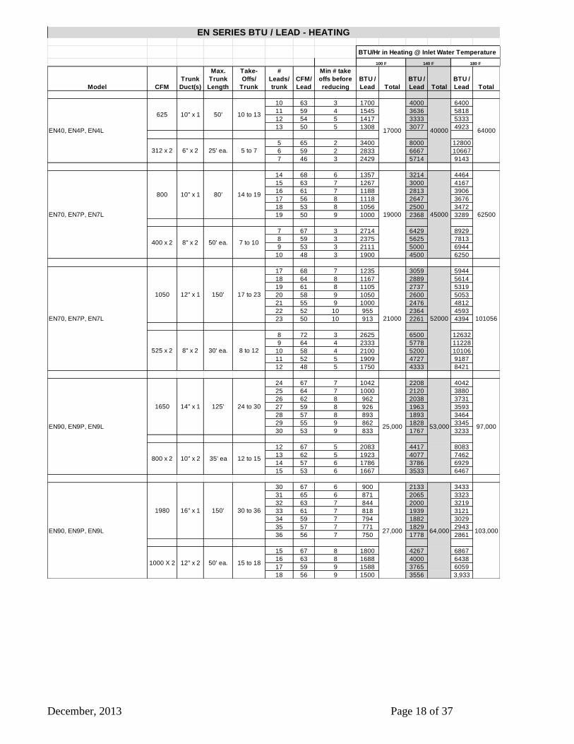
8. Follow the table above to determine the maximum and minimum number of leads available.
9. Return air ducting connects to the Enerboss using a 16” x 20” (500, 700, and 900 series) or 16”x
6” (400 series) opening. Vibration isolation (e.g. flex connector) is recommended at the return
air drop.
10. Return air should be picked up in a neutral, central location and is sized in the same way as a
traditional low velocity system (max. 700 fpm). Return air must be filtered prior to entering the
Enerboss using the filter provided.
11. A damper is required in the main return duct for balancing the HRV during commissioning.
December, 2013 Page 16 of 37
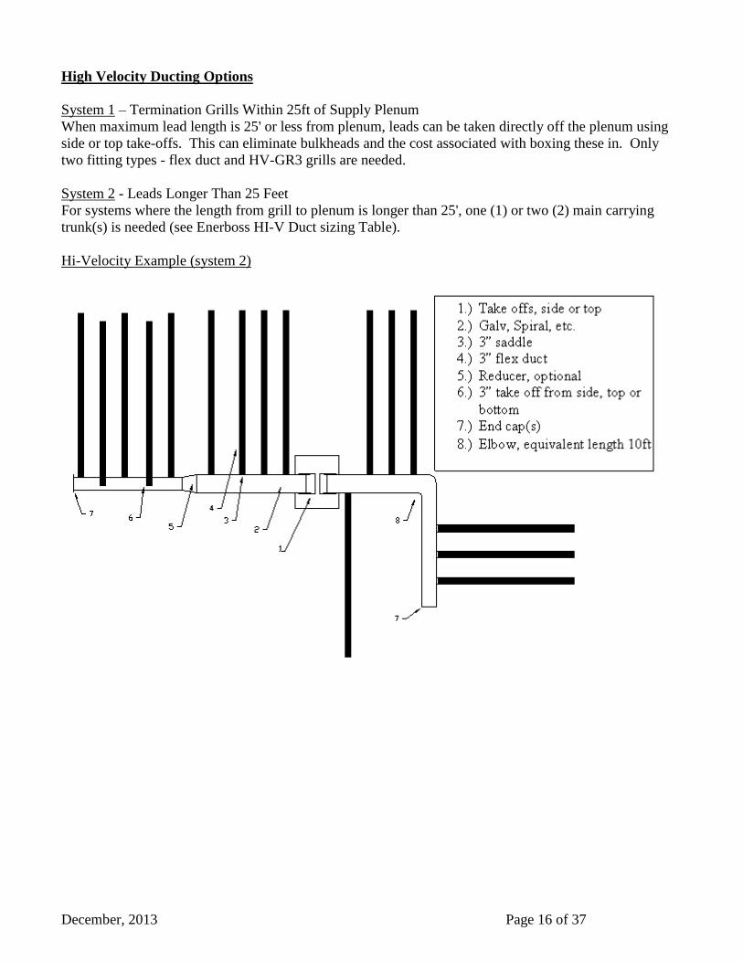
High Velocity Ducting Options
System 1 – Termination Grills Within 25ft of Supply Plenum
When maximum lead length is 25' or less from plenum, leads can be taken directly off the plenum using
side or top take-offs. This can eliminate bulkheads and the cost associated with boxing these in. Only
two fitting types - flex duct and HV-GR3 grills are needed.
System 2 - Leads Longer Than 25 Feet
For systems where the length from grill to plenum is longer than 25', one (1) or two (2) main carrying
trunk(s) is needed (see Enerboss HI-V Duct sizing Table).
Hi-Velocity Example (system 2)
December, 2013 Page 17 of 37
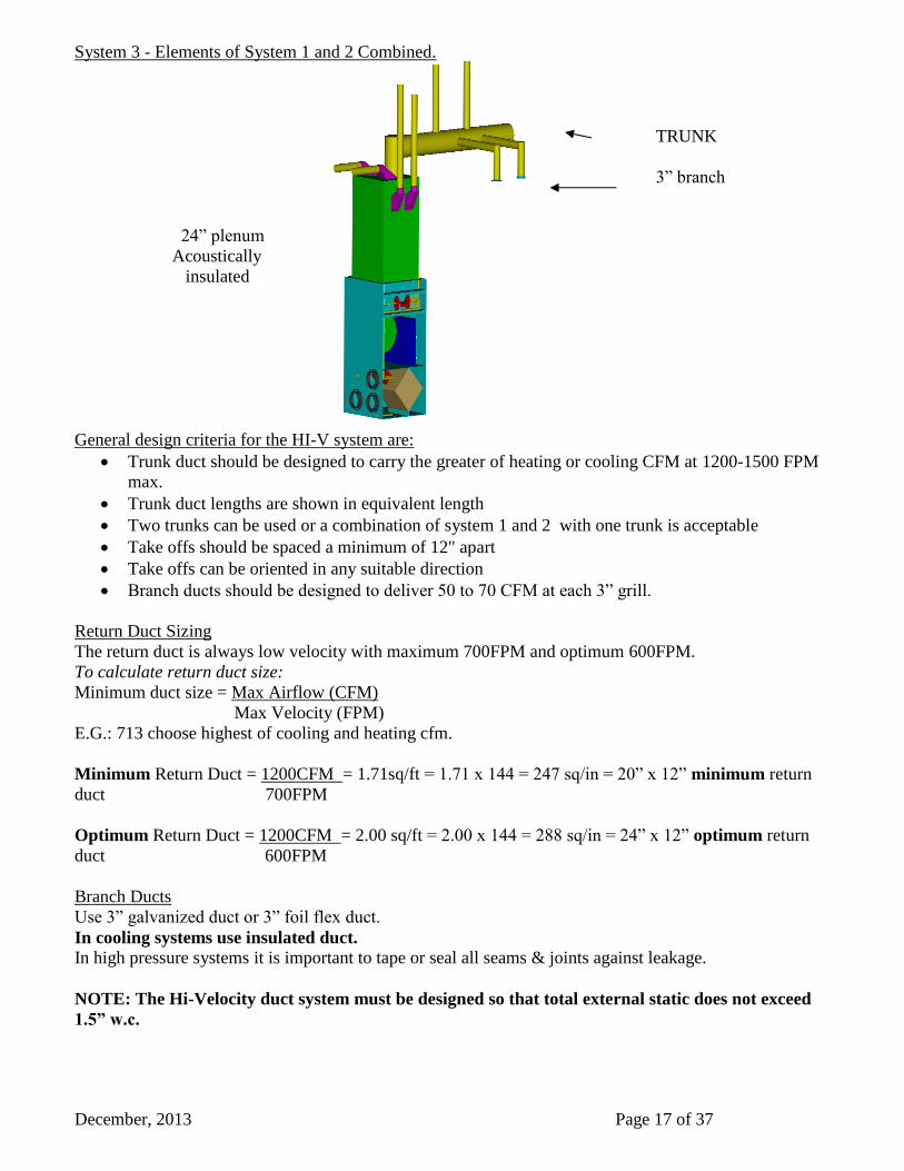
System 3 - Elements of System 1 and 2 Combined.
24” plenum
Acoustically
insulated
General design criteria for the HI-V system are:
Trunk duct should be designed to carry the greater of heating or cooling CFM at 1200-1500 FPM
max.
Trunk duct lengths are shown in equivalent length
Two trunks can be used or a combination of system 1 and 2 with one trunk is acceptable
Take offs should be spaced a minimum of 12" apart
Take offs can be oriented in any suitable direction
Branch ducts should be designed to deliver 50 to 70 CFM at each 3” grill.
Return Duct Sizing
The return duct is always low velocity with maximum 700FPM and optimum 600FPM.
To calculate return duct size:
Minimum duct size = Max Airflow (CFM)
Max Velocity (FPM)
E.G.: 713 choose highest of cooling and heating cfm.
Minimum Return Duct = 1200CFM = 1.71sq/ft = 1.71 x 144 = 247 sq/in = 20” x 12” minimum return
duct 700FPM
Optimum Return Duct = 1200CFM = 2.00 sq/ft = 2.00 x 144 = 288 sq/in = 24” x 12” optimum return
duct 600FPM
Branch Ducts
Use 3” galvanized duct or 3” foil flex duct.
In cooling systems use insulated duct.
In high pressure systems it is important to tape or seal all seams & joints against leakage.
NOTE: The Hi-Velocity duct system must be designed so that total external static does not exceed
1.5” w.c.
TRUNK
3” branch
December, 2013 Page 18 of 37
Model CFM
Trunk
Duct(s)
Max.
Trunk
Length
Take-
Offs/
Trunk
#
Leads/
trunk
CFM/
Lead
Min # take
offs before
reducing
BTU /
Lead Total
BTU /
Lead Total
BTU /
Lead Total
10 63 3 1700 4000 6400
11 59 4 1545 3636 5818
12 54 5 1417 3333 5333
13 50 5 1308 3077 4923
5 65 2 3400 8000 12800
6 59 2 2833 6667 10667
7 46 3 2429 5714 9143
14 68 6 1357 3214 4464
15 63 7 1267 3000 4167
16 61 7 1188 2813 3906
17 56 8 1118 2647 3676
18 53 8 1056 2500 3472
19 50 9 1000 2368 3289
7 67 3 2714 6429 8929
8 59 3 2375 5625 7813
9 53 3 2111 5000 6944
10 48 3 1900 4500 6250
17 68 7 1235 3059 5944
18 64 8 1167 2889 5614
19 61 8 1105 2737 5319
20 58 9 1050 2600 5053
21 55 9 1000 2476 4812
22 52 10 955 2364 4593
23 50 10 913 2261 4394
8 72 3 2625 6500 12632
9 64 4 2333 5778 11228
10 58 4 2100 5200 10106
11 52 5 1909 4727 9187
12 48 5 1750 4333 8421
24 67 7 1042 2208 4042
25 64 7 1000 2120 3880
26 62 8 962 2038 3731
27 59 8 926 1963 3593
28 57 8 893 1893 3464
29 55 9 862 1828 3345
30 53 9 833 1767 3233
12 67 5 2083 4417 8083
13 62 5 1923 4077 7462
14 57 6 1786 3786 6929
15 53 6 1667 3533 6467
30 67 6 900 2133 3433
31 65 6 871 2065 3323
32 63 7 844 2000 3219
33 61 7 818 1939 3121
34 59 7 794 1882 3029
35 57 7 771 1829 2943
36 56 7 750 1778 2861
15 67 8 1800 4267 6867
16 63 8 1688 4000 6438
17 59 9 1588 3765 6059
18 56 9 1500 3556 3,933
64,00027,000 103,000
1000 X 2 12" x 2 50' ea. 15 to 18
EN90, EN9P, EN9L
1980 16" x 1 150' 30 to 36
EN70, EN7P, EN7L
800 10" x 1
EN SERIES BTU / LEAD - HEATING
5 to 7
EN40, EN4P, EN4L
625
100 F
10" x 1 50' 10 to 13
140 F
400 x 2
312 x 2 6" x 2 25' ea.
101056
8" x 2 50' ea. 7 to 10
8 to 12
14 to 19
EN70, EN7P, EN7L
1050 12" x 1 150'
525 x 2 8" x 2 30' ea.
BTU/Hr in Heating @ Inlet Water Temperature
17000 40000
52000
17 to 23
62500
21000
35' ea 12 to 15
45000
64000
19000
180 F
80'
97,00053,000
125' 24 to 30
EN90, EN9P, EN9L 25,000
1650 14" x 1
800 x 2 10" x 2
December, 2013 Page 19 of 37
Max.
CFM
Trunk
Duct
Max.
Trunk
Length
Take-
Offs/
Trunk
# Leads/
trunk
CFM/
Lead
BTU / Lead Total
10 65 1921
11 59 1747
12 54 1601
13 50 1478
5 65 1921
6 59 1601
7 46 1372
13 65 1973
14 61 1832
15 57 1710
16 53 1603
17 50 1509
6 71 2138
7 61 1832
8 53 1603
9 47 1425
15 70 1822
16 66 1709
17 62 1608
18 58 1519
19 55 1439
20 53 1367
21 50 1302
8 66 1711
9 58 1521
10 53 1369
11 48 1244
17 71 2118
18 67 2000
19 63 1895
20 60 1800
21 57 1714
22 55 1636
23 52 1565
24 50 1500
9 67 2000
10 60 1800
11 55 1636
12 50 1500
24 67 2,000
25 64 1,920
26 62 1,846
27 59 1,778
28 57 1,714
29 55 1,655
30 53 1,600
12 67 2000
13 62 1846
14 57 1714
15 53 1600
30 67 2,000
31 65 1,935
32 63 1,875
33 61 1,818
34 59 1,765
35 57 1,714
36 56 1,667
15 67 2000
16 63 1875
17 59 1765
18 56 1667
10 to 13
325 x 2 6" x 2 25' ea.
650 8" x 1 50'
6 to 9
5 to 7
13 to 17850 10" x 1 100'
425 x 2 7" x 2
15 to 21
525 x 2 8" x 2 50' ea. 8 to 11
1050 12" x 1 150'
9 to 12
1200 12" x 1
BTU/ Hr Cooling
24264
30691
35789
120'
30' ea.
2000 16 x 1 150'
36000
17 to 24
600 x 2 8" x 2 30' ea.
30 to 36
60,000
1000 X 2 12 x 2 50' ea 15 to 18
48,000
24 to 301600 14 x 1 150'
800 x 2 10 x 2 50' ea 12 to 15
December, 2013 Page 20 of 37
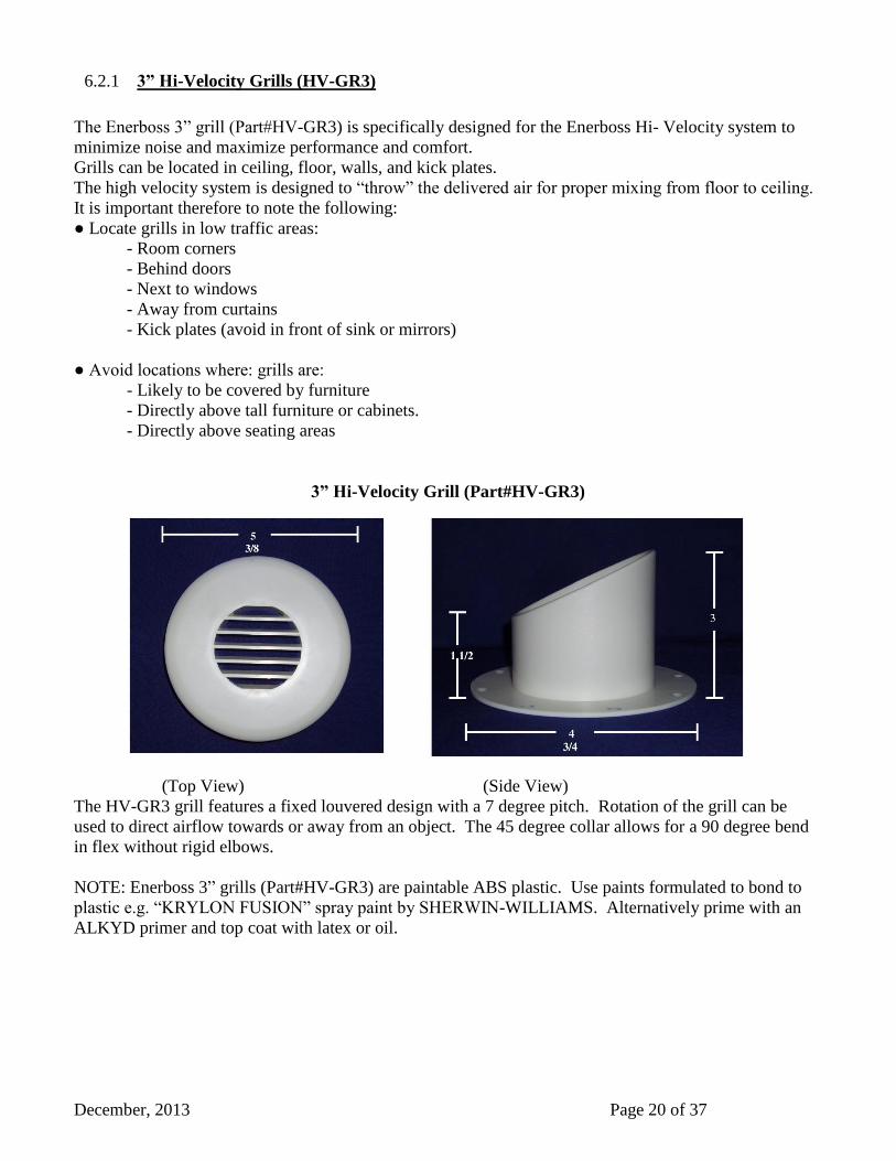
3” Hi-Velocity Grills (HV-GR3) 6.2.1
The Enerboss 3” grill (Part#HV-GR3) is specifically designed for the Enerboss Hi- Velocity system to
minimize noise and maximize performance and comfort.
Grills can be located in ceiling, floor, walls, and kick plates.
The high velocity system is designed to “throw” the delivered air for proper mixing from floor to ceiling.
It is important therefore to note the following:
● Locate grills in low traffic areas:
- Room corners
- Behind doors
- Next to windows
- Away from curtains
- Kick plates (avoid in front of sink or mirrors)
● Avoid locations where: grills are:
- Likely to be covered by furniture
- Directly above tall furniture or cabinets.
- Directly above seating areas
3” Hi-Velocity Grill (Part#HV-GR3)
(Top View) (Side View)
The HV-GR3 grill features a fixed louvered design with a 7 degree pitch. Rotation of the grill can be
used to direct airflow towards or away from an object. The 45 degree collar allows for a 90 degree bend
in flex without rigid elbows.
NOTE: Enerboss 3” grills (Part#HV-GR3) are paintable ABS plastic. Use paints formulated to bond to
plastic e.g. “KRYLON FUSION” spray paint by SHERWIN-WILLIAMS. Alternatively prime with an
ALKYD primer and top coat with latex or oil.

December, 2013 Page 21 of 37
6.3 HRV Ducting
Fresh air from the outside, exhaust air from space and exhaust air to outside all connect to the left hand
side of the unit via 6-inch diameter ducting. The Enerboss with integrated HRV allows for wet room
collection of exhaust air via an independent duct system. Six-inch diameter main lines branch off, reduce
in size and terminate in the kitchen, washroom, laundry, etc. HRAI and others offer guidelines for duct
sizing. Nu-Air recommends the use of these guidelines as good engineering practice.
Ducting To The Outside 6.3.1
Between the weather hoods and the HRV you must use fully insulated ducting with an integrated vapour
barrier. Insulated ducting with an integrated vapour barrier must also be used on all runs passing through
unheated areas. This will avoid condensation problems and energy losses.
The minimum RSI value of insulation should equal that of the local building codes.
Weather Hoods
1. Insulated flex duct slides over the galvanized sleeve of the weather hood.
2. Use sheathing tape (red) to join the inner duct to the hood's sleeve.
3. Tape the vapour barrier to back of the hood without compressing the insulation. Caulk or foam
seal around the collars and hoods to eliminate air and water leaks.
4. Locate the hoods for easy access to
the bird screen for cleaning
purposes.
Make the insulated duct that connects the
weather hoods to the HRV as short as
possible to minimize airflow restrictions.
Avoid sharp bends and stretch out the inner
lining of the flex duct as much as possible
to reduce static pressure and maximize
airflow.
Locating the Weather Hoods 6.3.2
There should be a minimum of 6’ (feet) of
separation between the fresh air and exhaust hoods. Supply hoods should be a minimum of 18” (inches)
above the ground level. Exhaust hoods should be at least 4 “(inches) above the ground level. Holes
through the wall should be 1” larger then the collar on the hood. Fresh air hoods must be 3’ away from
any other appliance exhaust vent or furnace vent.
Notes on Locating the Weather Hoods
Fresh air intakes should be located away from possible sources of contamination such as:
Gas meters Garbage containers
Oil fill pipes Vehicle exhaust
Dryer or other exhaust Within attics or crawl spaces

December, 2013 Page 22 of 37
DRAINS 7
Install drain spouts in the bottom of the HRV section. Tighten with a speed nut and connect 5/8" plastic
hose as shown below. Fill the trap with water.
COMMISSIONING 8
Commissioning of an Enerboss system requires both air and water side balancing. Units that have an
integrated HRV additionally require balancing of the supply and exhaust air streams to within 10% of
each other on high speed. Hot water flow and temperature adjustment to the air handler is required on all
units as is a thorough flushing of the plumbing to remove any loose solder sludge that can cause
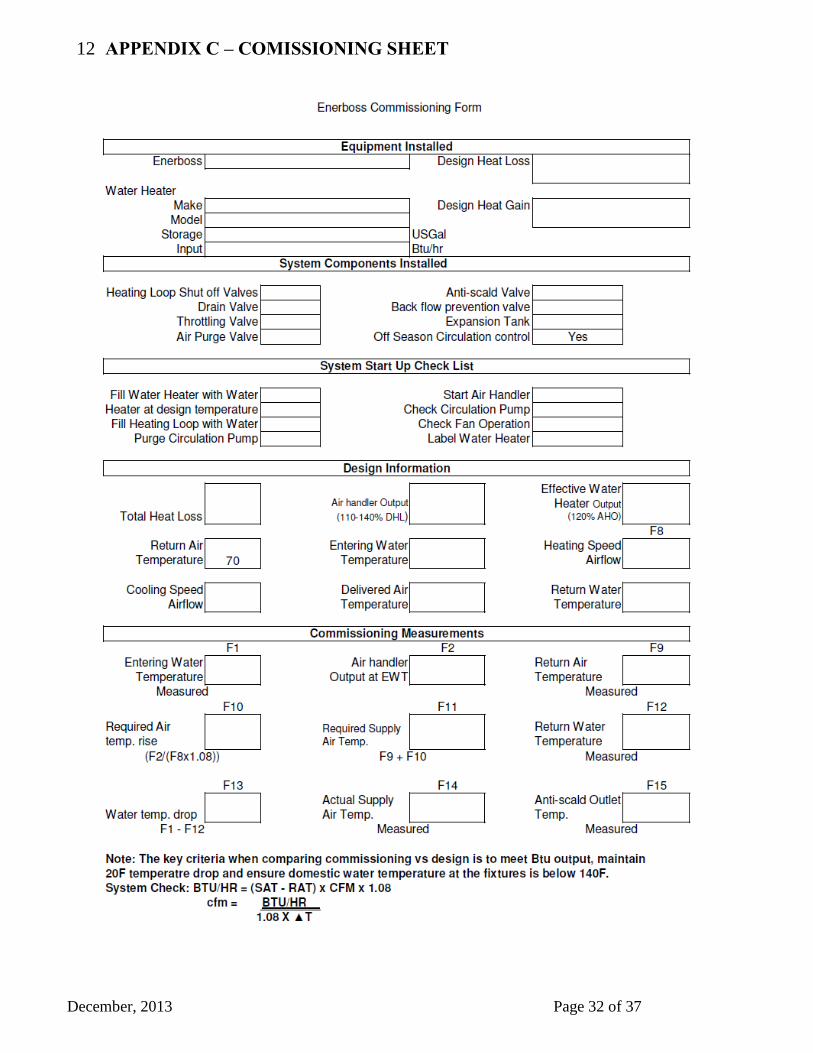
problems with the circulator pump and valves. Commissioning measurements should be recorded on
the form provided in Appendix C.
8.1 Supply Air Balancing
The supply air motor is an ECM operating in constant cfm mode. Adding static will not significantly
reduce the total air flow as you would expect with a psc motor. On ducted systems the amount of air at
each grille can be regulated with dampers.
8.2 HRV Balancing
The HRV exhaust air can be adjusted in low and high speed using the control board and the procedure
that follows. The amount of outside air is adjusted using dampers. A damper in the return air can be
closed (partially) to increase outside air flow or opened to decrease outside air flow. If outside air needs
to be further reduced, a balancing damper located in the HRV outside air compartment should be used.
When balancing the HRV:
-Close all windows, doors and fireplace dampers.
December, 2013 Page 23 of 37
-Turn off any exhaust systems such as bathroom fans, range hoods, central vacuums or dryers.
There are two modes of operation in which the HRV needs to be balanced.
1) High speed (High ventilation switch).
2) Low speed (thermostat fan ON, no heat or cool calls).
Balancing Sequence:
High Speed Balancing – set supply and exhaust to the specified flows
Low speed balancing – Fan On. Reduce the higher flow to match the lower
Balancing mode 1
High Speed Balancing:
With all dampers fully open and the exhaust fan speeds at the factory setting, run the air ahndler in high
ventilation mode.
a. Outside Air High Speed Adjustment
If the outside air flow is too low, gradually close the return air damper until the desired OA flow is
measured. If the outside air flow is too high gradually close the outside air balancing damper until the
OA flow is obtained.
b. Exhaust Air High Speed Adjustment
Locate the two blue pots on the circuit board. The top pot adjusts the exhaust fan HIGH speed. Turn
clockwise to increase and counterclockwise to decrease CFM. Adjust the exhaust flow rate to within 10%
of the OA rate.
Balancing Mode 2
Low Speed Balancing
Measure and record the flow rate of the Outside Air with the air handler in low speed ventilation (fan On,
thermostat system switch off) using the same method described above. Note: No adjustment can be
made to this flow without affecting the high speed flow and repeating the high speed balance.
Measure the exhaust air from building low speed flow. Use the lower pot to adjust the exhaust fan LOW
speed. Turn clockwise to increase and counterclockwise to decrease CFM. Adjust until the flow matches
that of the outside air.
NOTE: For low speed balancing a micro manometer should be used. Magnehelic gagues do not
have low enough resolution for these low pressures. Alternatively, velocity may be measured at
the outside hoods with a vane anemometer or similar
December, 2013 Page 24 of 37
8.3 Water Side Commissioning
Filling the water heater and setting system temperature: 8.3.1
1. At this point all valves should be closed and the system dry.
2. Open the cold water supply valve and a hot water tap.
3. Fill the water heater/boiler with water allowing air to escape at the open tap. Shut off the tap
when air has stopped escaping.
4. Using the boiler or water heater's control, set the system to operate at your design temperature.
See Equipment Selection Chart and preliminary design information forms.
5. Following the manufacturers instructions, start the water heater and allow it to reach the set
point.
For cases where high water temperatures are used, an anti-scald valve will be required. Set this to
120 F and verify by measuring the water temperature at the taps.
To fill the heating loop: 8.3.2
1. Connect a garden hose to the drain valve and direct water to a floor drain or similar.
2. Open the drain valve.
3. Open the heating loop's hot water supply shut off valve
4. Allow water to flow until only water (no air) is flowing at the drain.
5. Close the hot water shut off valve.
6. Open the return water shut off valve and allow water to flow until no air is escaping at the
drain.
7. Close the drain valve.
8. Open the hot water shut off valve.
Purging the pump and verifying flow in the heating loop: 8.3.3
1. Turn on electrical power to the Enerboss.
2. Set the house thermostat well above room temperature to force a call for heat.
3. Check that the circulating pump and fan are operating.
4. Hot water should be entering the fan coil and cooler water leaving.
5. Warm air should be exiting all supply grills/diffusers.
6. Apply the supplied warning label to the water heater near the aqua stat without covering any
existing labels.
Water flow Balancing: 8.3.4
This step should be done when both the room air temperature and water heater temperature are
stabilized.
NOTE: Return air temperature needs to be near 70 F ( 21 C).
1. Initiate a call for heat from the room thermostat.
2. Measure the supply (SAT) and return (RAT) air temperatures.
3. Measure the supply (SWT) and return (RWT) water temperatures
4. Calculate the heat output by the formula:
December, 2013 Page 25 of 37
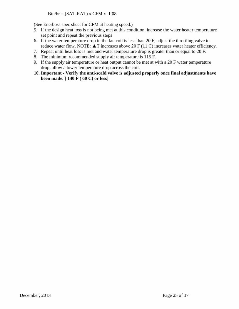
Btu/hr = (SAT-RAT) x CFM x 1.08
(See Enerboss spec sheet for CFM at heating speed.)
5. If the design heat loss is not being met at this condition, increase the water heater temperature
set point and repeat the previous steps
6. If the water temperature drop in the fan coil is less than 20 F, adjust the throttling valve to
reduce water flow. NOTE: ▲T increases above 20 F (11 C) increases water heater efficiency.
7. Repeat until heat loss is met and water temperature drop is greater than or equal to 20 F.
8. The minimum recommended supply air temperature is 115 F.
9. If the supply air temperature or heat output cannot be met at with a 20 F water temperature
drop, allow a lower temperature drop across the coil.
10. Important - Verify the anti-scald valve is adjusted properly once final adjustments have
been made. [ 140 F ( 60 C) or less]
December, 2013 Page 26 of 37
SERVICE AND MAINTENANCE: 9
Nu-Air recommends annual service and maintenance by a qualified HVAC contractor.
Disconnect the power supply to the Enerboss before attempting any service.
Maintenance should include:
QUARTERLY
1. Filter Replacement
- Return air – quarterly (Clean as often as necessary to prevent restriction of air flow).
- E/HRV - vacuum quarterly, replace annually.
2. Check outside hoods for debris and blockage (grass cuttings, leaves, insect and bird nests).
3. Wipe down all interior surfaces of the cabinet with disinfectant.
ANNUALLY
1. Coil cleaning – hot water and evaporator. Vacuum with a brush attachment. If necessary, wash with a
non toxic coil cleaner taking precautions not to wet motors and electrical components.
Access the A/C coil by removing the return air filter.
To access the heating coil, remove the EC motor/blower by disconnecting the two molex connectors
and removing the two screws at the front of the blower housing.
2. Fans – Vacuum or use a small brush to clean the blades of the main and HRV exhaust fans. To Clean
the main fan it may be necessary to remove the blower assembly as described above.
3. HRV core cleaning (aluminum and polypropylene) – remove the core by sliding it forward. Wash
with warm water and a mild detergent. Shake to remove excess water and replace.
4. ERV core cleaning (cellulose) - remove the core by sliding it forward. Vacuum only; washing will
damage the core and void the warranty.
5. Check the controls for proper operation.
6. Check E/HRV air flows and rebalance if necessary.
7. Check boiler/ water heater set point against commissioning report.
8. Inspect the duct work for air leaks (at joints and seams) and blockages (crushed ducts and crimps at
elbows).
December, 2013 Page 27 of 37
TROUBLESHOOTING 10
Pump fails to start - The pump may “stick” if it has not been operated for extended periods. Turn off the
power, remove the large screw on the end of the pump motor and turn the shaft several times with a
screwdriver. Replace the screw and start the pump.
Noisy pump – air may be trapped in the water circuit. Purge the system of entrapped air.
Insufficient or no heat –
Boiler/water heater temperature set too low
Air trapped in heating system – Purge system
Insufficient flow – check for pipping restrictions; open valves
Air handler inlet and outlet connections may be reversed
Undersized boiler or water heater
Undersized air handler
Water heater thermostat not properly calibrated
J4
J5
December, 2013 Page 28 of 37
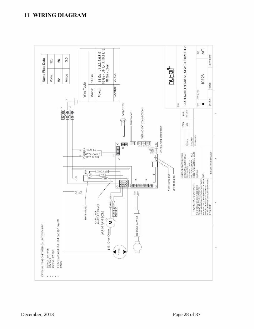
WIRING DIAGRAM 11
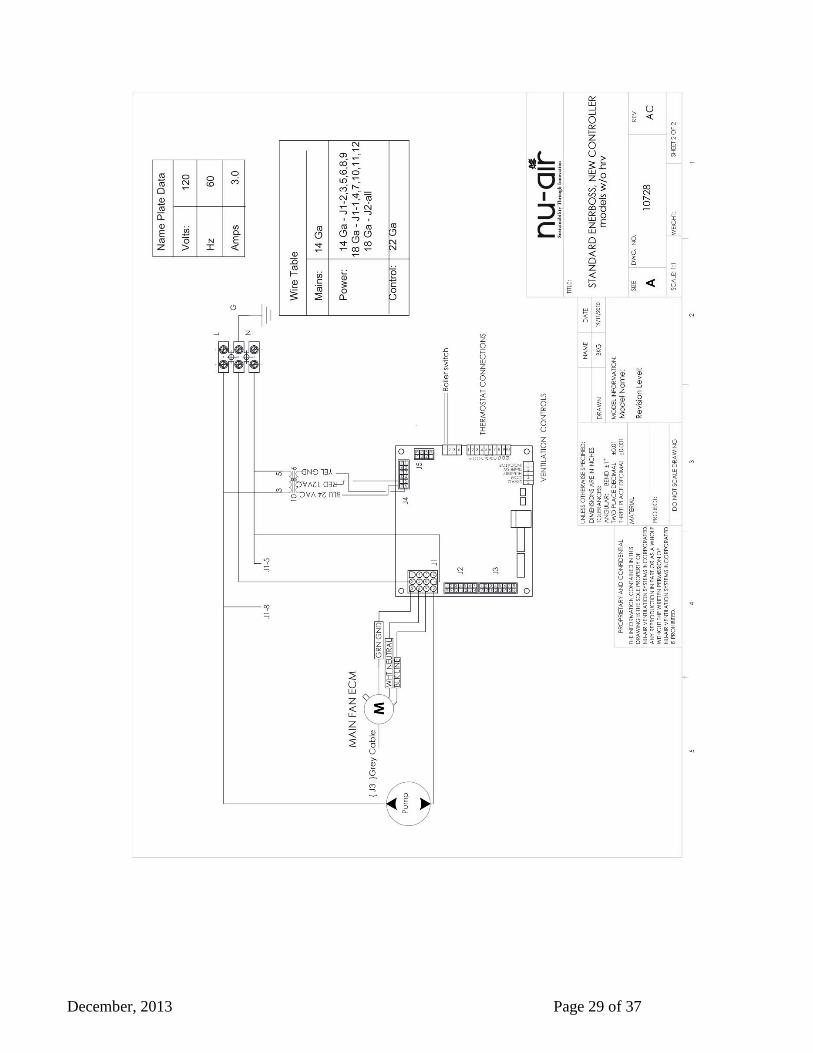
December, 2013 Page 29 of 37
December, 2013 Page 30 of 37
December, 2013 Page 31 of 37
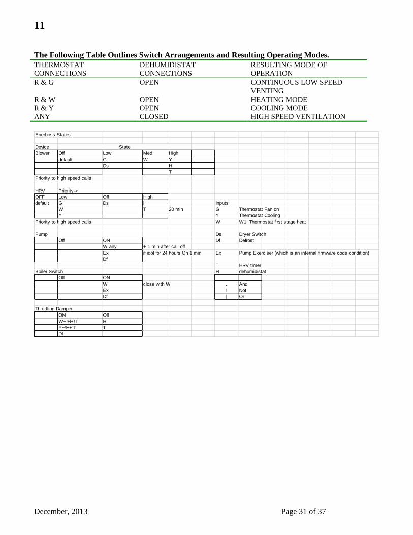
11
The Following Table Outlines Switch Arrangements and Resulting Operating Modes.
THERMOSTAT
CONNECTIONS
DEHUMIDISTAT
CONNECTIONS
RESULTING MODE OF
OPERATION
R & G OPEN CONTINUOUS LOW SPEED
VENTING
R & W OPEN HEATING MODE
R & Y OPEN COOLING MODE
ANY CLOSED HIGH SPEED VENTILATION
Enerboss States
Device State
Blower Off Low Med High
default G W Y
Ds H
T
Priority to high speed calls
HRV Priority->
OFF Low Off High
default G Ds H Inputs
W T 20 min G Thermostat Fan on
Y Y Thermostat Cooling
Priority to high speed calls W W1. Thermostat first stage heat
Pump Ds Dryer Switch
Off ON Df Defrost
W any + 1 min after call off
Ex if idol for 24 hours On 1 min Ex Pump Exerciser (which is an internal firmware code condition)
Df
T HRV timer
Boiler Switch H dehumidistat
Off ON
W close with W ₊ And
Ex ! Not
Df | Or
Throttling Damper
ON Off
W+!H+!T H
Y+!H+!T T
Df
December, 2013 Page 32 of 37
APPENDIX C – COMISSIONING SHEET 12
December, 2013 Page 33 of 37
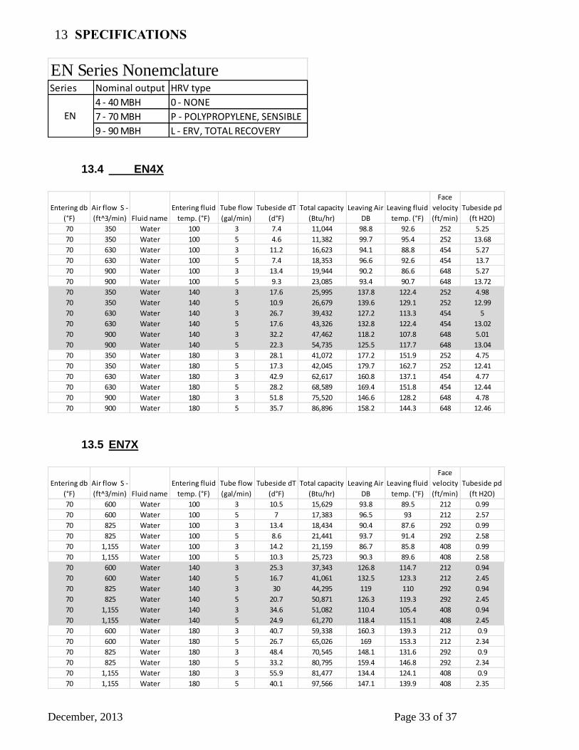
SPECIFICATIONS 13
13.4 EN4X
13.5 EN7X
EN Series NonemclatureSeries Nominal output HRV type
4 - 40 MBH 0 - NONE
7 - 70 MBH P - POLYPROPYLENE, SENSIBLE
9 - 90 MBH L - ERV, TOTAL RECOVERY
EN
Entering db
(°F)
Air flow S -
(ft^3/min) Fluid name
Entering fluid
temp. (°F)
Tube flow
(gal/min)
Tubeside dT
(d°F)
Total capacity
(Btu/hr)
Leaving Air
DB
Leaving fluid
temp. (°F)
Face
velocity
(ft/min)
Tubeside pd
(ft H2O)
70 350 Water 100 3 7.4 11,044 98.8 92.6 252 5.25
70 350 Water 100 5 4.6 11,382 99.7 95.4 252 13.68
70 630 Water 100 3 11.2 16,623 94.1 88.8 454 5.27
70 630 Water 100 5 7.4 18,353 96.6 92.6 454 13.7
70 900 Water 100 3 13.4 19,944 90.2 86.6 648 5.27
70 900 Water 100 5 9.3 23,085 93.4 90.7 648 13.72
70 350 Water 140 3 17.6 25,995 137.8 122.4 252 4.98
70 350 Water 140 5 10.9 26,679 139.6 129.1 252 12.99
70 630 Water 140 3 26.7 39,432 127.2 113.3 454 5
70 630 Water 140 5 17.6 43,326 132.8 122.4 454 13.02
70 900 Water 140 3 32.2 47,462 118.2 107.8 648 5.01
70 900 Water 140 5 22.3 54,735 125.5 117.7 648 13.04
70 350 Water 180 3 28.1 41,072 177.2 151.9 252 4.75
70 350 Water 180 5 17.3 42,045 179.7 162.7 252 12.41
70 630 Water 180 3 42.9 62,617 160.8 137.1 454 4.77
70 630 Water 180 5 28.2 68,589 169.4 151.8 454 12.44
70 900 Water 180 3 51.8 75,520 146.6 128.2 648 4.78
70 900 Water 180 5 35.7 86,896 158.2 144.3 648 12.46
Entering db
(°F)
Air flow S -
(ft^3/min) Fluid name
Entering fluid
temp. (°F)
Tube flow
(gal/min)
Tubeside dT
(d°F)
Total capacity
(Btu/hr)
Leaving Air
DB
Leaving fluid
temp. (°F)
Face
velocity
(ft/min)
Tubeside pd
(ft H2O)
70 600 Water 100 3 10.5 15,629 93.8 89.5 212 0.99
70 600 Water 100 5 7 17,383 96.5 93 212 2.57
70 825 Water 100 3 13.4 18,434 90.4 87.6 292 0.99
70 825 Water 100 5 8.6 21,441 93.7 91.4 292 2.58
70 1,155 Water 100 3 14.2 21,159 86.7 85.8 408 0.99
70 1,155 Water 100 5 10.3 25,723 90.3 89.6 408 2.58
70 600 Water 140 3 25.3 37,343 126.8 114.7 212 0.94
70 600 Water 140 5 16.7 41,061 132.5 123.3 212 2.45
70 825 Water 140 3 30 44,295 119 110 292 0.94
70 825 Water 140 5 20.7 50,871 126.3 119.3 292 2.45
70 1,155 Water 140 3 34.6 51,082 110.4 105.4 408 0.94
70 1,155 Water 140 5 24.9 61,270 118.4 115.1 408 2.45
70 600 Water 180 3 40.7 59,338 160.3 139.3 212 0.9
70 600 Water 180 5 26.7 65,026 169 153.3 212 2.34
70 825 Water 180 3 48.4 70,545 148.1 131.6 292 0.9
70 825 Water 180 5 33.2 80,795 159.4 146.8 292 2.34
70 1,155 Water 180 3 55.9 81,477 134.4 124.1 408 0.9
70 1,155 Water 180 5 40.1 97,566 147.1 139.9 408 2.35
December, 2013 Page 34 of 37
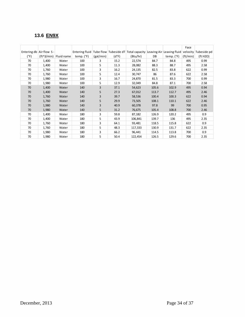
13.6 EN9X
Entering db
(°F)
Air flow S -
(ft^3/min) Fluid name
Entering fluid
temp. (°F)
Tube flow
(gal/min)
Tubeside dT
(d°F)
Total capacity
(Btu/hr)
Leaving Air
DB
Leaving fluid
temp. (°F)
Face
velocity
(ft/min)
Tubeside pd
(ft H2O)
70 1,400 Water 100 3 15.2 22,574 84.7 84.8 495 0.99
70 1,400 Water 100 5 11.3 28,082 88.3 88.7 495 2.58
70 1,760 Water 100 3 16.2 24,135 82.5 83.8 622 0.99
70 1,760 Water 100 5 12.4 30,747 86 87.6 622 2.58
70 1,980 Water 100 3 16.7 24,870 81.5 83.3 700 0.99
70 1,980 Water 100 5 12.9 32,049 84.8 87.1 700 2.58
70 1,400 Water 140 3 37.1 54,623 105.6 102.9 495 0.94
70 1,400 Water 140 5 27.3 67,012 113.7 112.7 495 2.46
70 1,760 Water 140 3 39.7 58,536 100.4 100.3 622 0.94
70 1,760 Water 140 5 29.9 73,505 108.1 110.1 622 2.46
70 1,980 Water 140 3 40.9 60,378 97.8 99 700 0.95
70 1,980 Water 140 5 31.2 76,675 105.4 108.8 700 2.46
70 1,400 Water 180 3 59.8 87,182 126.9 120.2 495 0.9
70 1,400 Water 180 5 43.9 106,841 139.7 136 495 2.35
70 1,760 Water 180 3 64.1 93,481 118.5 115.8 622 0.9
70 1,760 Water 180 5 48.3 117,333 130.9 131.7 622 2.35
70 1,980 Water 180 3 66.2 96,441 114.5 113.8 700 0.9
70 1,980 Water 180 5 50.4 122,454 126.5 129.6 700 2.35
December, 2013 Page 35 of 37
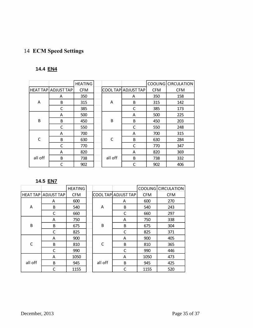
ECM Speed Settings 14
14.4 EN4
14.5 EN7
HEATING COOLING CIRCULATION
HEAT TAP ADJUST TAP CFM COOL TAP ADJUST TAP CFM CFM
A 600 A 600 270
B 540 B 540 243
C 660 C 660 297
A 750 A 750 338
B 675 B 675 304
C 825 C 825 371
A 900 A 900 405
B 810 B 810 365
C 990 C 990 446
A 1050 A 1050 473
B 945 B 945 425
C 1155 C 1155 520
all off all off
A A
B B
C C
HEATING COOLING CIRCULATION
HEAT TAP ADJUST TAP CFM COOL TAP ADJUST TAP CFM CFM
A 350 A 350 158
B 315 B 315 142
C 385 C 385 173
A 500 A 500 225
B 450 B 450 203
C 550 C 550 248
A 700 A 700 315
B 630 B 630 284
C 770 C 770 347
A 820 A 820 369
B 738 B 738 332
C 902 C 902 406
all off all off
A A
B B
C C

December, 2013 Page 36 of 37
14.6 EN9
HEATING COOLING CIRCULATION
HEAT TAP ADJUST TAP CFM COOL TAP ADJUST TAP CFM CFM
A 1400 A 1400 630
B 1260 B 1260 567
C 1540 C 1540 693
A 1600 A 1600 720
B 1440 B 1440 648
C 1760 C 1760 792
A 1800 A 1800 810
B 1620 B 1620 729
C 1980 C 1980 891
A 1900 A 1900 855
B 1710 B 1710 770
C 2090 C 2090 941
A A
B B
C C
all offall off
December, 2013 Page 37 of 37
WARRANTY 15
YOUR Enerboss
TRANSFERABLE WARRANTY
Should your Enerboss cease to function within Five (5) years of the date of original purchase due to
defective material of workmanship of the product, NU-AIR Ventilation Systems Inc. will supply a new or
rebuilt part FOB factory to replace the defective part. Delivery, installation, and labor cost would be your
responsibility.
Lifetime Core Warranty
If the aluminum or Polypropylene core in your NU-AIR Heat Recovery Ventilator fails due to a defect in
material or workmanship NU-AIR Ventilation Systems Inc. will supply a new core FOB factory to
replace the defective part. Delivery and labor costs are your responsibility.
(There is a two year warranty on our latent core)
Warranty Limitations
The above warranty does not cover damage to the unit while in your possession (other than damages
caused by defective parts or material) due to the following: 1) improper installation or unreasonable use
of unit: 2) failure to provide reasonable and necessary maintenance. If the unit is put to commercial use or
application other than consumer use, warranty is for a period of one (1) year. This warranty does not
cover water heaters, instantaneous water heaters, boilers or condenser units supplied or used with the
Enerboss. See water heater, boiler or compressor manufacturer's warranty.
P.O. Box 2758 16 Nelson St., Windsor, NS B0N 2T0 Tel: (902) 798-2261 Fax: (902) 798-2557
Email: [email protected] Website: www.nu-airventilation.com
Recommended