Reactive Power Solutions
Capacitor Catalogue 2016

Reactive Power Solutions
Havells Power Capacitors are designed and manufactured using S3 technology. It encompenses product with tripple shield
with differential disconnector in the event of any fault within due to environmental compatability. Automatic controlled V ACcum potting of “Element Modules” ensures fault remains localised and protects the installation inspite of hazards.Advance technologies adopted in our “Capacitors” offer you unmatched safety and outstanding performance under Indian conditions benefiting you month after month and every year from now on...Our commitment to manufacturing excellence and providing a world class quality products at affordable prices in creating your industry more energy efficient, now from even wider spectrum of products from Havells; we offer you a complete solution which is not only safe and reliable but also help you save your energy.
At Havells “Energy Conservation is our Motto”
About us

Reactive Power Solutions
INDEXIntroduction 8-15
Product overview 16-21
IPFC Panels 22-29
Power Capacitors - Cylinderical 30-44
Power Capacitors - Square 46-57
Anti Resonance Harmonic Filter 58-65
Micorprocessor controlled power factor controler 66-70
PFC fundamentals 71-83
Sahibabad Capacitor PlantSahibabad Capacitor Plant

4
Reactive Power Solutions
Sahibabad Capacitor PlantSahibabad Capacitor Plant

5
Reactive Power Solutions

6
Reactive Power Solutions
From Component to Solution

7
Reactive Power Solutions
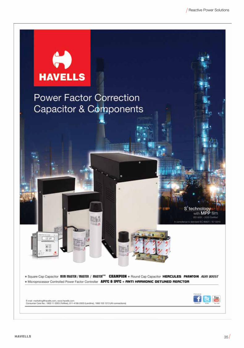
Range of Power Factor Correction Capacitors & Components
*Higher ratings on requrest. Banking solution available.
Cylindrical Square
(Splendid Duty)Range 1-30 KVAr
Range 6-350 KVAr
APFC Panel
(Heavy Duty)Range 1-25 KVAr
(Normal Duty)Range 1-15 KVAr
(Splendid Duty)Range 1-30 KVAr*
(Super Heavy Duty)Double Dielectric
Range 1-25 KVAr*
(Heavy Duty)Range 1-30 KVAr*
Range 5-100 KVAr
8 & 12 Steps
Anti Harmonic Detuned
Filter
Microprocessor Controlled
Power Factor Controller
TORRENT
CHAMP

8
Reactive Power Solutions
Power factor
Low power factor (cos f)results in
• Higher energy consumption and costs
• Less power distributed via the network
• Power loss in the network
• Higher transformer losses
• Increased voltage drop in power distribution networks.
Power FactorAs electrical power demand increasing day by day the awarness of the necessity of the energy saving is also increasing. So awarness of power quality increases. The power factor correction (PFC) and harmonic filtering is a need of the hour. Its a way of fast return of investment.
Havells is single window for power quality solution togeather with
• Application know-how • Technical skills • Extensive experience in the field of power quality improvement
Power factor improvement
Power factor improvement can be achieved by
• Compensation of reactive power with capacitors
• Active compensation – using semiconductors,
• Overexcited synchronous machine (motor / generator)
Types of PFC
(Detuned or conventional)
• Individual or fixed compensation (each reactive power producer is individually compensated)
• Group compensation (reactive power producers connected as a group and compensated as a whole)
• Central or automatic compensation (by a PFC system at a central point),
• Mixed compensation.
Important NotesFollowing points are applies to all products in this catalogue.
• HAVELLSiseitherunfamiliarwithindividualcustomerapplicationsorlessfamiliarwiththemthancustomersthemselves.Forthisreason, It is always ultimately incumbent on the customer to check and decide whether the HAVELLS product with the properties described in the product specification is suitable for use in particular customer application.
• Wealsopointoutthatinindividualcases,amalfunctionofcomponentsorfailurebeforetheendoftheirusualservicelifecannotbe completely ruled out in the current state of the art, even if they are operated as specified. In customer application requiring a very high level of operational safety and especially in customer applications in which the malfunction or failure of component could endanger human life or health (e.g. in accident prevention or lifesaving systems), it must therefore be ensured by means of suitable design of the customer application or other action taken by the customer (e.g. installation of protective circuitry or redundancy) that no injury or damage is sustained by third parties in the event of malfunction or failure of component.
• Thewarnings,cautionsandproduct–specificnotesmustbeobserved.
• Weconstantlystrivetoimproveourproducts,consequently,theproductdescribeinthispublicationmaychangefromtimetotime. Please check before or when you place the purchase order whether the product description and specifications contained in this catalogue.
• A worldwide network of partners • Continuous development • Sharing of information.
U
I U
I
Linear loads:voltage was followed by current.
Non linear load produce non sinusoidal currents when connected to sinusoidal voltage.
M3~
Uninterruptible Power Supply(optional)
EMC filterC
250/350/ 550 Hz
Overvoltageprotection
Tunedharmonicfilters
Linear loadwith fixedPFC
M3~
Overvoltageprotection
DynamicPFCsystems
Overvoltageprotection
Passiveharmonicfilters
(detuned PFCsystems)
Overvoltageprotection
Overvoltageprotection
Activeharmonicfilters
Power Factor Correction (PFC)and Harmonic Filtering
DC link(Aluminum electrolyticor film capacitors)
EMC filter
Frequency converter
C
Chargingresistor
Output filter

9
Reactive Power Solutions
Power Factor Correction - Components
Capacitor
Design of capacitorsMPP technology
kWh meter
Apparentpower
Capacitors forcompensation
kvarh meter
GridP
SQ
Power factor correction (PFC) capacitors produce the necessary leading reactive power to compensate the lagging reactive power. They should be capable of withstanding high inrush currents caused by switching operations (>100 · IR). If they are connected in parallel, i.e. as banks, the inrush current will increase (≥150 · IR) because the charging current comes from the power line as well as from other capacitors connected in parallel.
Metalized plastic compact capacitors with self-healing properties and a polypropylene dielectric. Film metallization with zinc/aluminum alloy results in high performance and a low film thickness allowing significantly more compact dimensions and a lower weight.
In the event of thermal or electrical overload, an electric breakdown occurs. The dielectric in the breakdown channel is broken down into highly compressed plasma that explodes out of the breakdown channel and pushes the dielectric layers apart. The discharge contin-ues within the spreading charge continues within the spreading plasma via the metal layers so that the metal surrounding the faulty area is completely burnt out. This produces perfect isolation of the faulty area within microseconds. The self-healing process results in negligible capacitance loss – less than 100 pF per event. The capaci-tor remains fully functional during the entire process.
1. Dielectric2. Metalized electrodes3. Material displacing shock wave4. Air gap with metal vapor 5, 6. Plasma zone7. Boundary layer between gas phase dielectric and plasma8. Breakdown channel9. Gas phase dielectric10. Zone of displaced metalization and dielectric (isolating region)
Self-healingx
r1 10
4 2
42
6
6
8 10 1
2 4
245
5
10 101
1
399 7
37 9
30 µm 10 µm

10
Reactive Power Solutions
Power Factor Correction
Capacitors are most cost effective and reliable static devices which
can generate and supply reactive power (energy). Capacitors consume virtually negligible active power and able to produce reactive power locally, thus enabling Power Factor Correction for inductive loads.
The vector diagram given aside summarize the concept of power factor correction/ improvement by reactive power compensation with capacitors.
cosf1 = Initial power factor
cosf2 = Target power factor
KVA2<KVA1
Active Power (kW)• Itispowerusedbytheloadstomeetthefunctionaloutputrequirements
Reactive Power (KVAr)• Itispowerusedbytheloadtomeetitsmagneticfieldequipmentsandtherequirements
of magnetic losses• Thereactivepowerisalways900 out of phase with respects to the active power• TheunitnormallyusedtoexpressthereactivepowerisVAr(inpracticalusageKVAr)• TheapparentpowerKVAisthevectorsomeofactiveandreactivepower
Power Factor
The power factor is the cosine of the angle between Active power
and Apparent power
• PowerFactor(cosf) =
• KVA=KW2+KVAr2
• kW=KVAxcosf
• tanf =
Effects of Reactive Energy
It is now obvious that both active and reactive energy are necessary inputs in all electrical systems however the flow of reactive power has certain negative aspects which results in the increased cost of electrical systems and also drops in the efficiency of systems operationsThe increased flow of reactive power results in the following. Adverse condition• Overloadingoftransformers• HigherkVAdemandonsystem• Highervoltagedropthroughoutthesystems.
Activepower(KW)Apparent power(KVA)
Introduction - Principle of Reactive Energy Management
Active energy
Reactive energy
PowerGeneration
Transmissionnetwork Motor
Active energy
Reactive energy
Active energy Transmissionnetwork Motor
Active energy
Capacitors
PowerGeneration
ϕ 1 ϕ 2 kvar2
kvarCkVA 1
kVA 2
kW
kvar (leading)c
kvar 1
Under normal operating conditions certain electrical loads (e.g. induction motors, welding
equipment, arc furnaces and fluorescent lighting) draw not only active power from the
supply, but also inductive reactive power (KVAr).This reactive power is necessary for the
equipment to operate correctly but could be interpreted as an undesirable burden on the
supply. The power factor of a load is defined as the ratio of active power to apparent power,
i.e.kW:kVAandisreferredtoascosf. The closer cosf is to unity, the less reactive power
isdrawnfromthesupply:
Power Factor = Cos f
Cos f=P(kW)/S(kVA)
Reactive Power KVAr
Q = S2 - P2
Active
P = S2-Q2
[KW]
Cos f = P/S
Sin f = Q/S
Q = S Sin f
Q = P tan f
f = phase displacement
S1 = uncompensated apparent power
S2 = compensated power with
capacitor for compensation
Active
S = P2-Q2
[kVA]
KVArkW
• UsingIPFCpanelatvariouspointsofthedistributionnetwork-
Here automatic power factor correction takes place with the help
of power factor controller and power contactors by switching
in/out 4/6/8/12 steps of capacitor banks as the power factor
varies.
• Increase IR losses leading to additional heating and loss of energy
• Increaseintheratingofswitchgearcablesandotherprotectivedevices
• Reductionofvoltageattheloadend

11
Reactive Power Solutions
Savings on the electricity bill• Decrease in KVA demand
• Eliminatepenaltiesonreactiveenergy
• Reducepowerlossintransformers
Example: Loss reduction in a 630KVA transformer
PW=6500W(assumed)withaninitialPowerFactor=0.7
Withpowerfactorcorrectionweobtainafinalpower
factor = 0.98
Thelossesbecome:3316Wi.e.areductionof49%
Increase in available powerA high power factor optimizes an electrical installation.
Fitting PFC equipment on Low Voltage side of transformers increases available power at secondary of LV transformers.
The table shows the increased available power at the transformer output by improving power factor from 0.7 to1.
Example :Calculation for additional load inKW that canbe connectedbyimproving Power Factor
Load = 500KVA
Initial PF (cosf1) = 0.7
Target PF (cosf2) = 0.95
cosf1 =kW1/KVA
kW1 = KVA x cosf1
=350kW
kW2 = KVA x cosf2
=475kW
AdditionalkWthatcanbeconnected
= 475-350
=125kW
%ofadditionalload =125/350x100
=36%
Power Factor Additional available
power(kW)
0.7 0%
0.8 +14%
0.85 +21%
0.90 +29%
0.95 +36%
1.00 +43%
Reduction in Electricity bill
Reduction in KVAr
Reduction in kVA Demand
Reduction in Switchgear Rating
Reduction in line losses / Cable losses
Reduction in voltage regulations
Reduction in Line Current Reduced Loading on Transformer
Benefits of Reactive Energy Management• By providing proper Reactive management system the adverse effects of flow of reactive energy can be minimized
• Followingtableprovidessomeofthebenefitsofreactiveenergymanagement
Copper loss =
=
=
PF1
PF2
0.70.98
0.70.98
(((
)))
X Full load copper loss
X Full load copper loss
X6500W
2
2
2
=3316W
=3183W
Savings=6500W–3316W

12
Reactive Power Solutions
Reduction in line currentInstallation of PFC equipment results in,• Reduction in current drawn from source• Reduction in conductor cross section and reduced losses
The table shows the Multiplying Factor(MF) for the conductor crosssectionincrease for fall in power factor.
Example: Calculation of reduction of line current if PF improved from 0.60 to 1.00Load=350kW
1. KVA1 = kW/PF1
= 350 / 1.00 = 350 kVA I1 = KVA x 1000 / Ö3 x V = 583 x 1000 / Ö3 x 440 = 765 A (Before PF compensation)
2. KVA2 = kW/PF2
= 350/0.60 = 583 KVA I2 = KVA x 1000 / Ö3 x V = 350 x 1000 / Ö3 x 440 = 459 A (After PF compensation)
Savings in line current Multiplying Factor = I1 / I2 = 765 / 459 = 1.67
Improvement in voltage regulation Installing PFC equipment increases the voltage at the point of connection, which compensates the fall in voltage due to poor Power Factor
DV =Voltage ImprovementV=SystemVoltageWithoutCapacitorsQ = Capacitors Rating in MVArS = System Fault Level In MVA
Example:For a 150 KVAr, 440V capacitor & Systemfault level of 15 MVA.
DV = 4.4 Volts
Power Factor MF
1 1
0.80 1.25
0.80 1.67
0.40 2.50
DVV
QS
=
DVV
QS
=
DV 440 x 0.1515
=

13
Reactive Power Solutions
Types of compensation Broadly, there are two types of compensation:
• Fixed compensation
• Variable compensation
Fixed compensation
This arrangement uses one or more capacitors to provide a constant level of compensation.
Control may be
• Manual:bycircuit-breakerorload-breakswitch
• Semi-automatic:bycontactor
• Direct connection to an appliance and switched with it
These capacitors are applied:
• At the terminals of inductive loads (mainly motors), at bus bars connecting numerous small motors and inductive appliances for which individual compensation would be too costly
• In cases where the load factor is reasonably constant
Variable compensation
• IPFC panels
• Contactor / Thyristor based
• ePFC
• Electronic VAr compensator with IGBT
The primary reason for Variable compensation is the variation of loads in the network. In many applications the process are not constant through out the day, hence the reactive energy required varies as per the load profile, to eliminate the risk of leading power factor and to optimize the kVA demand, the variable compensation techniques are used.
Modes of compensationThe selection of the Power Factgor Correction equipment can follow 3 levels of compensation
• Central compensation
• Group compensation
• Individual compensaion
Central Compensation
Supply
Transformer
CircuitBreaker
Group Compensation
Individual Compensation
Individual Compensation
Individual Compensation
Group Compensation
Individual Compensation
MLoad
MLoad
MLoad
MLoad
14
Reactive Power Solutions
Current achievable (Actual) (Target)Tan f Cos f cos f 0.80 0.82 0.85 0.88 0.90 0.92 0.94 0.96 0.98 1.00 Factor K
The table below shows the values for typical power factors according to the formula
Qc = PA * (tanf1-tan f2)
Qc (KVAr) = PMotor
* K = active power (kW) * factor “K” P
Motor=S * cos j = apparent power * cos f
tan f 1 + f 2 according to cos f values ref. Table
Example:ACTUAL motor power P = 100 kWActual cos f 0.65TARGET cos f 0.96Factor K from table 0.88Capacitor reactive power QcQc = 100 * 0.88 = 88 KVAr (say 90 KVAr)
3.18 0.30 2.43 2.43 2.56 2.64 2.70 2.75 2.82 2.89 2.98 3.182.96 0.32 2.21 2.26 2.34 2.42 2.48 2.53 2.60 2.67 2.76 2.962.77 0.34 2.02 2.07 2.15 2.23 2.28 2.34 2.41 2.48 2.56 2.772.59 0.36 1.84 1.89 1.97 2.05 2.10 2.17 2.23 2.30 2.39 2.592.43 0.38 1.68 1.73 1.81 1.89 1.95 2.01 2.07 2.14 2.23 2.432.29 0.40 1.54 1.59 1.67 1.75 1.81 1.87 1.93 2.00 2.09 2.292.16 0.42 1.41 1.46 1.54 1.62 1.68 1.73 1.80 1.87 1.96 2.062.04 0.44 1.29 1.34 1.42 1.50 1.56 1.61 1.68 1.75 1.84 2.041.93 0.46 1.18 1.23 1.31 1.39 1.45 1.50 1.57 1.64 1.73 1.931.83 0.48 1.08 1.13 1.21 1.29 1.34 1.40 1.47 1.54 1.62 1.831.73 0.50 0.98 1.03 1.11 1.19 1.25 1.31 1.37 1.45 1.63 1.731.64 0.52 0.89 0.94 1.02 1.10 1.16 1.22 1.28 1.35 1.44 1.641.56 0.54 0.81 0.86 0.94 1.02 1.07 1.13 1.20 1.27 1.36 1.561.48 0.56 0.73 0.78 0.86 0.94 1.00 1.05 1.12 1.19 1.28 1.481.40 0.58 0.65 0.70 0.78 0.86 0.92 0.98 1.04 1.11 1.20 1.401.33 0.60 0.58 0.63 0.71 0.79 0.85 0.91 0.97 1.04 1.13 1.331.30 0.61 0.55 0.60 0.68 0.76 0.81 0.87 0.94 1.01 1.10 1.301.27 0.62 0.52 0.57 0.65 0.73 0.78 0.84 0.91 0.99 1.06 1.271.23 0.63 0.48 0.53 0.61 0.69 0.75 0.81 0.87 0.94 1.03 1.231.20 0.64 0.45 0.50 0.58 0.66 0.72 0.77 0.84 0.91 1.00 1.201.17 0.65 0.42 0.47 0.55 0.63 0.68 0.74 0.81 0.88 0.97 1.171.14 0.66 0.39 0.44 0.52 0.60 0.65 0.71 0.78 0.85 0.94 1.141.11 0.67 0.36 0.41 0.49 0.57 0.63 0.68 0.75 0.82 0.90 1.111.08 0.68 0.33 0.38 0.46 0.54 0.59 0.65 0.72 0.79 0.88 1.081.05 0.69 0.30 0.35 0.43 0.51 0.56 0.62 0.69 0.76 0.85 1.051.02 0.70 0.27 0.32 0.40 0.48 0.54 0.59 0.66 0.73 0.82 1.020.99 0.71 0.24 0.29 0.37 0.45 0.51 0.57 0.63 0.70 0.79 0.990.96 0.72 0.21 0.26 0.34 0.42 0.48 0.54 0.60 0.67 0.76 0.960.94 0.73 0.19 0.24 0.32 0.40 0.45 0.51 0.58 0.65 0.73 0.940.91 0.74 0.16 0.21 0.29 0.37 0.42 0.48 0.55 0.62 0.71 0.910.88 0.75 0.13 0.18 0.26 0.34 0.40 0.46 0.52 0.59 0.68 0.880.86 0.76 0.11 0.16 0.24 0.32 0.37 0.43 0.50 0.57 0.65 0.860.83 0.77 0.08 0.13 0.21 0.29 0.34 0.40 0.47 0.54 0.63 0.830.80 0.78 0.05 0.10 0.18 0.26 0.32 0.38 0.44 0.51 0.60 0.800.78 0.79 0.03 0.08 0.16 0.24 0.29 0.35 0.42 0.49 0.57 0.780.75 0.80 0.05 0.13 0.21 0.27 0.32 0.39 0.46 0.55 0.750.72 0.81 0.10 0.18 0.24 0.30 0.36 0.43 0.52 0.720.70 0.82 0.08 0.16 0.21 0.27 0.34 0.41 0.49 0.700.67 0.83 0.05 0.13 0.19 0.25 0.31 0.38 0.47 0.670.65 0.84 0.03 0.11 0.16 0.22 0.29 0.36 0.44 0.650.62 0.85 0.08 0.14 0.19 0.26 0.33 0.42 0.620.59 0.86 0.05 0.11 0.17 0.23 0.30 0.39 0.590.57 0.87 0.08 0.14 0.21 0.28 0.36 0.570.54 0.88 0.06 0.11 0.18 0.25 0.34 0.540.51 0.89 0.03 0.09 0.15 0.22 0.31 0.510.48 0.90 0.06 0.12 0.19 0.26 0.480.46 0.91 0.03 0.10 0.17 0.25 0.460.43 0.92 0.07 0.14 0.22 0.430.40 0.93 0.04 0.11 0.19 0.400.36 0.94 0.07 0.16 0.360.33 0.95 0.13 0.330.29 0.96 0.09 0.290.25 0.97 0.05 0.250.20 0.98 0.200.14 0.99 0.14

15
Reactive Power Solutions
Current achievable (Actual) (Target)Tan f Cos f cos f 0.80 0.82 0.85 0.88 0.90 0.92 0.94 0.96 0.98 1.00 Factor K
3.18 0.30 2.43 2.43 2.56 2.64 2.70 2.75 2.82 2.89 2.98 3.182.96 0.32 2.21 2.26 2.34 2.42 2.48 2.53 2.60 2.67 2.76 2.962.77 0.34 2.02 2.07 2.15 2.23 2.28 2.34 2.41 2.48 2.56 2.772.59 0.36 1.84 1.89 1.97 2.05 2.10 2.17 2.23 2.30 2.39 2.592.43 0.38 1.68 1.73 1.81 1.89 1.95 2.01 2.07 2.14 2.23 2.432.29 0.40 1.54 1.59 1.67 1.75 1.81 1.87 1.93 2.00 2.09 2.292.16 0.42 1.41 1.46 1.54 1.62 1.68 1.73 1.80 1.87 1.96 2.062.04 0.44 1.29 1.34 1.42 1.50 1.56 1.61 1.68 1.75 1.84 2.041.93 0.46 1.18 1.23 1.31 1.39 1.45 1.50 1.57 1.64 1.73 1.931.83 0.48 1.08 1.13 1.21 1.29 1.34 1.40 1.47 1.54 1.62 1.831.73 0.50 0.98 1.03 1.11 1.19 1.25 1.31 1.37 1.45 1.63 1.731.64 0.52 0.89 0.94 1.02 1.10 1.16 1.22 1.28 1.35 1.44 1.641.56 0.54 0.81 0.86 0.94 1.02 1.07 1.13 1.20 1.27 1.36 1.561.48 0.56 0.73 0.78 0.86 0.94 1.00 1.05 1.12 1.19 1.28 1.481.40 0.58 0.65 0.70 0.78 0.86 0.92 0.98 1.04 1.11 1.20 1.401.33 0.60 0.58 0.63 0.71 0.79 0.85 0.91 0.97 1.04 1.13 1.331.30 0.61 0.55 0.60 0.68 0.76 0.81 0.87 0.94 1.01 1.10 1.301.27 0.62 0.52 0.57 0.65 0.73 0.78 0.84 0.91 0.99 1.06 1.271.23 0.63 0.48 0.53 0.61 0.69 0.75 0.81 0.87 0.94 1.03 1.231.20 0.64 0.45 0.50 0.58 0.66 0.72 0.77 0.84 0.91 1.00 1.201.17 0.65 0.42 0.47 0.55 0.63 0.68 0.74 0.81 0.88 0.97 1.171.14 0.66 0.39 0.44 0.52 0.60 0.65 0.71 0.78 0.85 0.94 1.141.11 0.67 0.36 0.41 0.49 0.57 0.63 0.68 0.75 0.82 0.90 1.111.08 0.68 0.33 0.38 0.46 0.54 0.59 0.65 0.72 0.79 0.88 1.081.05 0.69 0.30 0.35 0.43 0.51 0.56 0.62 0.69 0.76 0.85 1.051.02 0.70 0.27 0.32 0.40 0.48 0.54 0.59 0.66 0.73 0.82 1.020.99 0.71 0.24 0.29 0.37 0.45 0.51 0.57 0.63 0.70 0.79 0.990.96 0.72 0.21 0.26 0.34 0.42 0.48 0.54 0.60 0.67 0.76 0.960.94 0.73 0.19 0.24 0.32 0.40 0.45 0.51 0.58 0.65 0.73 0.940.91 0.74 0.16 0.21 0.29 0.37 0.42 0.48 0.55 0.62 0.71 0.910.88 0.75 0.13 0.18 0.26 0.34 0.40 0.46 0.52 0.59 0.68 0.880.86 0.76 0.11 0.16 0.24 0.32 0.37 0.43 0.50 0.57 0.65 0.860.83 0.77 0.08 0.13 0.21 0.29 0.34 0.40 0.47 0.54 0.63 0.830.80 0.78 0.05 0.10 0.18 0.26 0.32 0.38 0.44 0.51 0.60 0.800.78 0.79 0.03 0.08 0.16 0.24 0.29 0.35 0.42 0.49 0.57 0.780.75 0.80 0.05 0.13 0.21 0.27 0.32 0.39 0.46 0.55 0.750.72 0.81 0.10 0.18 0.24 0.30 0.36 0.43 0.52 0.720.70 0.82 0.08 0.16 0.21 0.27 0.34 0.41 0.49 0.700.67 0.83 0.05 0.13 0.19 0.25 0.31 0.38 0.47 0.670.65 0.84 0.03 0.11 0.16 0.22 0.29 0.36 0.44 0.650.62 0.85 0.08 0.14 0.19 0.26 0.33 0.42 0.620.59 0.86 0.05 0.11 0.17 0.23 0.30 0.39 0.590.57 0.87 0.08 0.14 0.21 0.28 0.36 0.570.54 0.88 0.06 0.11 0.18 0.25 0.34 0.540.51 0.89 0.03 0.09 0.15 0.22 0.31 0.510.48 0.90 0.06 0.12 0.19 0.26 0.480.46 0.91 0.03 0.10 0.17 0.25 0.460.43 0.92 0.07 0.14 0.22 0.430.40 0.93 0.04 0.11 0.19 0.400.36 0.94 0.07 0.16 0.360.33 0.95 0.13 0.330.29 0.96 0.09 0.290.25 0.97 0.05 0.250.20 0.98 0.200.14 0.99 0.14

16
Reactive Power Solutions
Parameter Unit Hercules Phantom Agri Boost
Reference Standard IS 13340 / IEC 60831 IS 13340 / IEC 60831 IS 13340
Power (Rated Capacitance) Qn 1 – 30 KVAr 1 – 25 KVAr 1 – 15 KVAr
Tolerance 0 –10% 0 –10% 0 –10%
Connection Delta Delta Delta
Rated voltage VR 400 – 525 400 – 525 415 – 440
Rated Frequency fR 50 / 60 Hz 50 / 60 Hz 50 / 60 Hz
Max. Ratings
Max. Permisible Voltage Vmax.
VR+10%(upto8hdaily)VR+15%(upto30mindaily)VR+20%(upto5mindaily)VR+30%(upto1mindaily)
VR+10%(upto8hdaily)VR+15%(upto30mindaily)VR+20%(upto5mindaily)VR+30%(upto1mindaily)
VR+10%(upto8hdaily)VR+15%(upto30mindaily)VR+20%(upto5mindaily)VR+30%(upto1mindaily)
Max. Permisible Current Imax.Up to 1.3 x IR (up to 1.5 x IR incl. combined
effects of harmonics, over voltages and capacitance)
Up to 1.3 x IR (up to 1.5 x IR incl. combined effects of harmonics, over voltages and capacitance)
Up to 1.3 x IR (up to 1.5 x IR incl. combined effects of harmonics, over voltages and capacitance)
Max. Transient Inrush Current Handling Capacity IS up to 200 x IR up to 250 x IR up to 200 x IRTest Data
AC Test Voltage Terminal to Terminal VTT 2.15 x UN, 2 Sec. 2.15 x UN, 2 Sec. 1.75 x UN, 2 Sec.
Insulation Voltage Between Terminal & Container VTC 3600 V AC, 2 Sec. 3600 V AC, 2 Sec. 3600 V AC, 2 Sec.
Losses:
– Dielectric <0.2W/KVAr <0.2W/KVAr <0.2W/KVAr
– Total* <0.4W/KVAr <0.4W/KVAr <0.4W/KVAr
Climatic Category
Ambient Temperature 0 C-25 / D; max. temp. 550 C; max mean 24h = 45 0C;max. mean 1 year = 35 0C; lowest temp. = -25 0C
-25 / D; max. temp. 550 C; max mean 24h = 45 0C;max. mean 1 year = 35 0C; lowest temp. = -25 0C
-25 / D; max. temp. 550 C; max mean 24h = 45 0C;max. mean 1 year = 35 0C; lowest temp. = -25 0C
Max. humidity Hrel 95% 95% 95%
Max. Permisible Altitute 4000 M above sea level 4000 M above sea level 4000 M above sea level
Mean Life Expectancy tLD (co) 100000 Hrs 130000 Hrs 100000 Hrs
Design Data
Case Material / Shape Aluminium / Cylindrical Aluminium / Cylindrical Aluminium / Cylindrical
Dimensions According to specification table page no. 33, 34 According to Specification Table Page No. 39, 40 According to Specification Table Page No. 44
Dielectric Polypropylene Film Polypropylene Film Polypropylene Film
Impregnation Soft Resin Soft Resin Soft Resin
Fixing Threaded Bolt M8 / M12 Threaded Bolt M8 / M12 Threaded Bolt M8 / M12
Max. Tourque for Fixing Nm 4 Nm / 10 Nm 4 Nm / 10 Nm 4 Nm / 10 Nm
Mounting PositionUpright. Horizontal mounting with additional head support possible.
Upright. Horizontal mounting with additional head support Possible.
Upright. Horizontal mounting with additional head support Possible.
Terminals Upto 5KVAr fast on and above clamp Upto 5KVAr fast on and above clamp WireTerminal
Degree of Protection Safety IP20 optional IP54 IP20 optional IP54 IP54
Max. Tourque for Connection Terminals (6 KVAr and above) Nm 2.5 Nm 2.5 Nm
Safety
Mechnical Safety Tear of fuses, overpressure disconnector Tear of fuses, overpressure disconnector Tear of fuses, overpressure disconnector
Discharge Device Resister Resister Resister
Discharge Device Time Sec. ≤60 Sec (50 V) ≤60 Sec (50 V) ≤60 Sec (50 V)
Cooling Natural or Forced Natural or Forced Natural or Forced
Max. Switching Operations Max. 5000 Nos. Per Year Max. 5000 Nos. Per Year Max. 5000 Nos. Per Year
Ordering Code QHNTC* QHHTC* QHATC*
Power factor correction capacitors - Cylindrical
* without discharge resister

17
Reactive Power Solutions
Parameter Unit Hercules Phantom Agri Boost
Reference Standard IS 13340 / IEC 60831 IS 13340 / IEC 60831 IS 13340
Power (Rated Capacitance) Qn 1 – 30 KVAr 1 – 25 KVAr 1 – 15 KVAr
Tolerance 0 –10% 0 –10% 0 –10%
Connection Delta Delta Delta
Rated voltage VR 400 – 525 400 – 525 415 – 440
Rated Frequency fR 50 / 60 Hz 50 / 60 Hz 50 / 60 Hz
Max. Ratings
Max. Permisible Voltage Vmax.
VR+10%(upto8hdaily)VR+15%(upto30mindaily)VR+20%(upto5mindaily)VR+30%(upto1mindaily)
VR+10%(upto8hdaily)VR+15%(upto30mindaily)VR+20%(upto5mindaily)VR+30%(upto1mindaily)
VR+10%(upto8hdaily)VR+15%(upto30mindaily)VR+20%(upto5mindaily)VR+30%(upto1mindaily)
Max. Permisible Current Imax.Up to 1.3 x IR (up to 1.5 x IR incl. combined
effects of harmonics, over voltages and capacitance)
Up to 1.3 x IR (up to 1.5 x IR incl. combined effects of harmonics, over voltages and capacitance)
Up to 1.3 x IR (up to 1.5 x IR incl. combined effects of harmonics, over voltages and capacitance)
Max. Transient Inrush Current Handling Capacity IS up to 200 x IR up to 250 x IR up to 200 x IRTest Data
AC Test Voltage Terminal to Terminal VTT 2.15 x UN, 2 Sec. 2.15 x UN, 2 Sec. 1.75 x UN, 2 Sec.
Insulation Voltage Between Terminal & Container VTC 3600 V AC, 2 Sec. 3600 V AC, 2 Sec. 3600 V AC, 2 Sec.
Losses:
– Dielectric <0.2W/KVAr <0.2W/KVAr <0.2W/KVAr
– Total* <0.4W/KVAr <0.4W/KVAr <0.4W/KVAr
Climatic Category
Ambient Temperature 0 C-25 / D; max. temp. 550 C; max mean 24h = 45 0C;max. mean 1 year = 35 0C; lowest temp. = -25 0C
-25 / D; max. temp. 550 C; max mean 24h = 45 0C;max. mean 1 year = 35 0C; lowest temp. = -25 0C
-25 / D; max. temp. 550 C; max mean 24h = 45 0C;max. mean 1 year = 35 0C; lowest temp. = -25 0C
Max. humidity Hrel 95% 95% 95%
Max. Permisible Altitute 4000 M above sea level 4000 M above sea level 4000 M above sea level
Mean Life Expectancy tLD (co) 100000 Hrs 130000 Hrs 100000 Hrs
Design Data
Case Material / Shape Aluminium / Cylindrical Aluminium / Cylindrical Aluminium / Cylindrical
Dimensions According to specification table page no. 33, 34 According to Specification Table Page No. 39, 40 According to Specification Table Page No. 44
Dielectric Polypropylene Film Polypropylene Film Polypropylene Film
Impregnation Soft Resin Soft Resin Soft Resin
Fixing Threaded Bolt M8 / M12 Threaded Bolt M8 / M12 Threaded Bolt M8 / M12
Max. Tourque for Fixing Nm 4 Nm / 10 Nm 4 Nm / 10 Nm 4 Nm / 10 Nm
Mounting PositionUpright. Horizontal mounting with additional head support possible.
Upright. Horizontal mounting with additional head support Possible.
Upright. Horizontal mounting with additional head support Possible.
Terminals Upto 5KVAr fast on and above clamp Upto 5KVAr fast on and above clamp WireTerminal
Degree of Protection Safety IP20 optional IP54 IP20 optional IP54 IP54
Max. Tourque for Connection Terminals (6 KVAr and above) Nm 2.5 Nm 2.5 Nm
Safety
Mechnical Safety Tear of fuses, overpressure disconnector Tear of fuses, overpressure disconnector Tear of fuses, overpressure disconnector
Discharge Device Resister Resister Resister
Discharge Device Time Sec. ≤60 Sec (50 V) ≤60 Sec (50 V) ≤60 Sec (50 V)
Cooling Natural or Forced Natural or Forced Natural or Forced
Max. Switching Operations Max. 5000 Nos. Per Year Max. 5000 Nos. Per Year Max. 5000 Nos. Per Year
Ordering Code QHNTC* QHHTC* QHATC*
18
Reactive Power Solutions
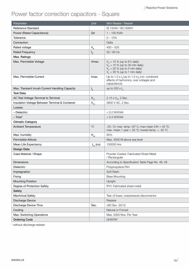
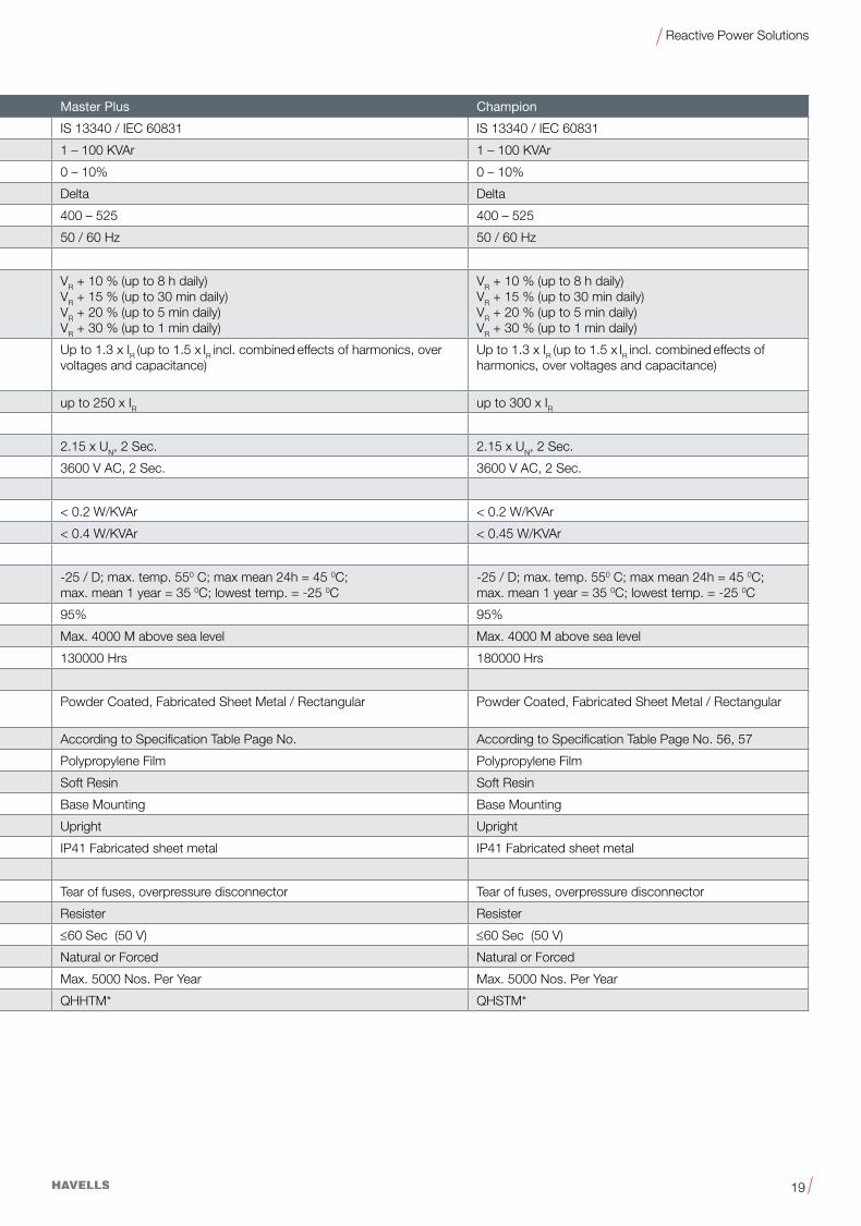
Parameter Unit Mini Master / Master Master Plus Champion
Reference Standard IS 13340 / IEC 60831 IS 13340 / IEC 60831 IS 13340 / IEC 60831
Power (Rated Capacitance) Qn 1 – 100 KVAr 1 – 100 KVAr 1 – 100 KVAr
Tolerance 0 – 10% 0 – 10% 0 – 10%
Connection Delta Delta Delta
Rated voltage VR 400 – 525 400 – 525 400 – 525
Rated Frequency fR 50 / 60 Hz 50 / 60 Hz 50 / 60 Hz
Max. Ratings
Max. Permisible Voltage Vmax. VR+10%(upto8hdaily)VR+15%(upto30mindaily)VR+20%(upto5mindaily)VR+30%(upto1mindaily)
VR+10%(upto8hdaily)VR+15%(upto30mindaily)VR+20%(upto5mindaily)VR+30%(upto1mindaily)
VR+10%(upto8hdaily)VR+15%(upto30mindaily)VR+20%(upto5mindaily)VR+30%(upto1mindaily)
Max. Permisible Current Imax. Up to 1.3 x IR (up to 1.5 x IR incl. combined
effects of harmonics, over voltages and capacitance)
Up to 1.3 x IR (up to 1.5 x IR incl. combined effects of harmonics, over voltages and capacitance)
Up to 1.3 x IR (up to 1.5 x IR incl. combined effects of harmonics, over voltages and capacitance)
Max. Transient Inrush Current Handling Capacity IS up to 200 x IR up to 250 x IR up to 300 x IRTest Data
AC Test Voltage Terminal to Terminal VTT 2.15 x UN, 2 Sec. 2.15 x UN, 2 Sec. 2.15 x UN, 2 Sec.
Insulation Voltage Between Terminal & Container VTC 3600 V AC, 2 Sec. 3600 V AC, 2 Sec. 3600 V AC, 2 Sec.
Losses:
– Dielectric <0.2W/KVAr <0.2W/KVAr <0.2W/KVAr
– Total* <0.4W/KVAr <0.4W/KVAr <0.45W/KVAr
Climatic Category
Ambient Temperature 0C -25 / D; max. temp. 550 C; max mean 24h = 45 0C;max. mean 1 year = 35 0C; lowest temp. = -25 0C
-25 / D; max. temp. 550 C; max mean 24h = 45 0C;max. mean 1 year = 35 0C; lowest temp. = -25 0C
-25 / D; max. temp. 550 C; max mean 24h = 45 0C;max. mean 1 year = 35 0C; lowest temp. = -25 0C
Max. humidity Hrel 95% 95% 95%
Permisible Altitute Max. 4000 M above sea level Max. 4000 M above sea level Max. 4000 M above sea level
Mean Life Expectancy tLD (co) 100000 Hrs 130000 Hrs 180000 Hrs
Design Data
Case Material / Shape Powder Coated, Fabricated Sheet Metal / Rectangular
Powder Coated, Fabricated Sheet Metal / Rectangular Powder Coated, Fabricated Sheet Metal / Rectangular
Dimensions According to Specification Table Page No. 48, 49 According to Specification Table Page No. According to Specification Table Page No. 56, 57
Dielectric Polypropylene Film Polypropylene Film Polypropylene Film
Impregnation Soft Resin Soft Resin Soft Resin
Fixing Base Mounting Base Mounting Base Mounting
Mounting Position Upright Upright Upright
Degree of Protection Safety IP41 Fabricated sheet metal IP41 Fabricated sheet metal IP41 Fabricated sheet metal
Safety
Mechnical Safety Tear of fuses, overpressure disconnector Tear of fuses, overpressure disconnector Tear of fuses, overpressure disconnector
Discharge Device Resister Resister Resister
Discharge Device Time Sec. ≤60 Sec (50 V) ≤60 Sec (50 V) ≤60 Sec (50 V)
Cooling Natural or Forced Natural or Forced Natural or Forced
Max. Switching Operations Max. 5000 Nos. Per Year Max. 5000 Nos. Per Year Max. 5000 Nos. Per Year
Ordering Code QHNTM* QHHTM* QHSTM*
Power factor correction capacitors - Square
* without discharge resister
19
Reactive Power Solutions
Parameter Unit Mini Master / Master Master Plus Champion
Reference Standard IS 13340 / IEC 60831 IS 13340 / IEC 60831 IS 13340 / IEC 60831
Power (Rated Capacitance) Qn 1 – 100 KVAr 1 – 100 KVAr 1 – 100 KVAr
Tolerance 0 – 10% 0 – 10% 0 – 10%
Connection Delta Delta Delta
Rated voltage VR 400 – 525 400 – 525 400 – 525
Rated Frequency fR 50 / 60 Hz 50 / 60 Hz 50 / 60 Hz
Max. Ratings
Max. Permisible Voltage Vmax. VR+10%(upto8hdaily)VR+15%(upto30mindaily)VR+20%(upto5mindaily)VR+30%(upto1mindaily)
VR+10%(upto8hdaily)VR+15%(upto30mindaily)VR+20%(upto5mindaily)VR+30%(upto1mindaily)
VR+10%(upto8hdaily)VR+15%(upto30mindaily)VR+20%(upto5mindaily)VR+30%(upto1mindaily)
Max. Permisible Current Imax. Up to 1.3 x IR (up to 1.5 x IR incl. combined
effects of harmonics, over voltages and capacitance)
Up to 1.3 x IR (up to 1.5 x IR incl. combined effects of harmonics, over voltages and capacitance)
Up to 1.3 x IR (up to 1.5 x IR incl. combined effects of harmonics, over voltages and capacitance)
Max. Transient Inrush Current Handling Capacity IS up to 200 x IR up to 250 x IR up to 300 x IRTest Data
AC Test Voltage Terminal to Terminal VTT 2.15 x UN, 2 Sec. 2.15 x UN, 2 Sec. 2.15 x UN, 2 Sec.
Insulation Voltage Between Terminal & Container VTC 3600 V AC, 2 Sec. 3600 V AC, 2 Sec. 3600 V AC, 2 Sec.
Losses:
– Dielectric <0.2W/KVAr <0.2W/KVAr <0.2W/KVAr
– Total* <0.4W/KVAr <0.4W/KVAr <0.45W/KVAr
Climatic Category
Ambient Temperature 0C -25 / D; max. temp. 550 C; max mean 24h = 45 0C;max. mean 1 year = 35 0C; lowest temp. = -25 0C
-25 / D; max. temp. 550 C; max mean 24h = 45 0C;max. mean 1 year = 35 0C; lowest temp. = -25 0C
-25 / D; max. temp. 550 C; max mean 24h = 45 0C;max. mean 1 year = 35 0C; lowest temp. = -25 0C
Max. humidity Hrel 95% 95% 95%
Permisible Altitute Max. 4000 M above sea level Max. 4000 M above sea level Max. 4000 M above sea level
Mean Life Expectancy tLD (co) 100000 Hrs 130000 Hrs 180000 Hrs
Design Data
Case Material / Shape Powder Coated, Fabricated Sheet Metal / Rectangular
Powder Coated, Fabricated Sheet Metal / Rectangular Powder Coated, Fabricated Sheet Metal / Rectangular
Dimensions According to Specification Table Page No. 48, 49 According to Specification Table Page No. According to Specification Table Page No. 56, 57
Dielectric Polypropylene Film Polypropylene Film Polypropylene Film
Impregnation Soft Resin Soft Resin Soft Resin
Fixing Base Mounting Base Mounting Base Mounting
Mounting Position Upright Upright Upright
Degree of Protection Safety IP41 Fabricated sheet metal IP41 Fabricated sheet metal IP41 Fabricated sheet metal
Safety
Mechnical Safety Tear of fuses, overpressure disconnector Tear of fuses, overpressure disconnector Tear of fuses, overpressure disconnector
Discharge Device Resister Resister Resister
Discharge Device Time Sec. ≤60 Sec (50 V) ≤60 Sec (50 V) ≤60 Sec (50 V)
Cooling Natural or Forced Natural or Forced Natural or Forced
Max. Switching Operations Max. 5000 Nos. Per Year Max. 5000 Nos. Per Year Max. 5000 Nos. Per Year
Ordering Code QHNTM* QHHTM* QHSTM*

20
Reactive Power Solutions
Reference Standard IEC 61558 / IS 5553
Tolerance of Inductance ±3%
Harmonics*
V3=0.5%VR(dutycycle=100%)
V5=6.0%VR(dutycycle=100%)
V7=5.0%VR(dutycycle=100%)
V11=3.5%VR(dutycycle=100%)
V13=3.0%VR(dutycycle=100%)
Effective current Irms = (I12+I3
2 ... I132)
Fundamental current I1 = 1.06 . IR (50 Hz or 60 Hz current of capacitor)
Insulation (winding-core) 3 kV
Temperature protection Microswitch (NC)
Dimensional drawings and terminals See specific datasheets
Three-phase filter reactors to EN 60289 / IEC 61558
Frequency 50 Hz or 60 Hz
Voltage 400, 440 V AC
Output 5 … 100 KVAr
Detuning Factors 5.67%,7%,14%
Cooling Natural
Ambient temperature 40 °C
Humidity 95%
Insulation class H
Class of protection I
Enclosure IP00
Max. Permissible Attitude Max. 4000M above sea level
Terminals Lugs / Busbar
Design Data
Dimensions According to specification table page no
WeightApprox. According to specification table page no
Safety- All reactors are provided with a sepaerate screw terminal for the temperature switch (opening switch) which is located indisde the central coil.
Response Temperature 1400C
Voltage 250 V AC (<4A) ... 500 V AC (<2A)
Ordering Code QHDTM*
Technical Data
Power factor control component - Anti Harmoni Detuned Filer

21
Reactive Power Solutions
Power factor control component - Microprocessor Controlled Power Factor Controller
Technical Data & Limit Values
Reference Standard IEC 61010-1
Parameters Unit Intelligent Power Factor Controller
Dimension m.m. 144 x 144 x 85
Weight kg. 0.75
Ambient conditions
Operating temperature Range °C –10 °C ... + 60 °C
Storage temperature Range °C –20 °C ... + 65 °C
Mounting position Flush Mounting in Vertical Plane
Protection class IP 54 ( Front)
Operation
Rated Operational Voltage V AC 230VAC+-20%
Rated Operational Current I 50 mA – 6A (--/5 A Current Transformer)
Network Type SinglePhase,2Wire
Mains frequency Hz 50 / 60
Power consumption
Current I <2VA
Voltage V <10 VA
Target Power Factor Cos Φ 0.8 < cos Φ <= 1 (Inductive)
Switching Outputs
Capacitor Steps 6,8 , 12 Steps (Max.) + 1 Alarm
Relay Output Contact Max250AC,1000W
Switching time range 2 Sec. – 30 Min.
Control modes Automatic Bank Selection in accordance to Reactive Power Compensation
Ordering code QHOSRA*

22
Reactive Power Solutions
Range
• OutputRating:6-350KVAr(OtherKVArratingonrequest)
• VoltageRating:440V
Ref. Standard
• IEC61921/IS8623
The design of the Low Voltage Power Factor Correction banks
and accessories shall comply with the following standards
• IEC60831: Part 1 & 2-Shunt power capacitors of the self
healing type for a.c systems having rated voltage up to and
including 1kV.
Introduction
Modern Power network cater to a wide variety of electrical and
power electronic loads, which create a varying power demand
on the supply system. It therefore becomes practically difficult
to maintain a consistent power factor by the use of fixed
compensation i.e. fixed capacitor to be manually switched ON
and OFF to suit the variation of the load. This will lead to situation
where the installation can have a low power factor causing higher
demand charges and levy of power factor penalties.
In addition to not being able to achieve the desired power
factor that the use of fixed compensation can result in leading
power factor under certain load conditions, which is unhealthy
for the installation as it can result in over voltages, saturation of
transformers, mal-operation of diesel generating sets, penalties
by electricity supply authorities etc.
It is therefore necessary to automatic switching operation of the
suitable capacitor depending upon the load fluctuations without
manual intervention. This compensation is best suited to the load
requirements.
It can be achieved by using Automatic Power Factor Correction
(APFC) System which can maintain consistently high power
factor, without leading power factor operation.
• IEC 60439-3: Low voltage switchgear and control gear
assemblies. Particular requirements for low-voltage switchgear
and control gear assemblies intended to be installed in places
where unskilled persons have access for their use-Distribution
boards.
• IEC60947:LowVoltageSwitchgear
Part2:MoldedCaseCircuitBreakers&AircircuitBreakers
Part4:PowerContactors
• IEC60269:LVFuses
• IEC60529:Degreeofprotectionprovidedbyenclosure
• IEC60044-1:Currenttransformers.
• IEC60664-1/IEC61326:PowerFactorController.
-Automatic Power Factor Correction System

23
Reactive Power Solutions
Salient Features
• CorrectiontoUnitPowerFactor.
• ModularDesignwhichallowseasierassembly,installation
and maintenance by the user.
• Designedtominimizeinstallationtimeandcost.
• AdvancedMicroprocessorrelay
• TheincomerMCCBprovidedhasupto35KAfault
interrupting capability.
• ManualCapacitorSwitchingCapability.
• IndicatinglightforCapacitorstagedisplay.
• IndustrialDuty,SafetydisconnectsMetallizeddielectric
capacitors, less than 0.2 watts per KVAr losses.
• ColourSiemensGreyRAL.
• Specialcableusedhenceitcanwithstandtemperature.
• StepSwitching.
• CapacitorDutyContactorwithdumpingresistance.
• SwitchoptionAutoorManual.
• Busbarismadeofcopper.
• ProvisionofRotaryhandleforincomerMCCB.
Principle Operation
• Tocontinuouslysenseandmonitortheloadconditionsby
the use of the external CT (whose output is fed to the control
relay).
• ToautomaticallyswitchONandswitchOFFrelevant
capacitor steps to ensure consistent power factor.
• Toensureeasyuserinterfaceforenablingreliable
understanding of system operation, such as display of real
time power factor, number of switching operations carried out
etc.
• Toprotectagainstanyelectricalfaultsinamannerthat
will ensure safe isolation of the power factor correction
equipment.
Disadvantages of having poor power factor are generally understood as follows:
• MorekVAdemandforthegivenkWloadandpenaltyforpoor
power factor, hence higher running cost (electricity bill).
• More line current for the given kW load and hence higher
rated transformer, switchgears and cables are required, hence
higher capital cost.
• MorethelinecurrentforthegivenkWloadandhencehigher
losses at the transformer, switchgears and cables, hence
higher running cost.
• More line current for the given kW load- poor utilization of
all electrical distribution network and hence poor return on
investment.
• Higher voltagedrops in thedistribution network hencepoor
performance of electrical equipments resulting in production
loss.
• Higher voltage fluctuations hence damage to electrical
equipments resulting in production loss.
Need to correct the poor power factor:
If we are able to correct the poor power factor to near unity on
all occasions at all loads, we can bring down the kVA demand,
line losses, increase the utilization of the distribution equipments,
increase the performance of electrical equipments, avoid damages
to electrical equipments and avoid production losses due to power
related problems. Another major advantage is that unity power
factor not only avoids penalty but also brings in incentive from
Electricity Board for higher power factor. All the above savings in
revenue expenditures improves the bottom line of the company
directly adding to the profit. Hence the investment on a good
power factor correction system will give an attractive payback.
Subsequently the return on the investment will be high.
Various Methods Of Power Factor Correction System
Using Power Capacitors, the poor power factor can be corrected
inthefollowingmethods:
• By providing fixed value of capacitors to the distribution
network at various points. They will be switched in/out as per
the load manually.

24
Reactive Power Solutions
Technical Data & Limit Values
Details Rating
Power Rating 6-15 KVAr 25-50 KVAr 75-150 KVAr 175-250 KVAr 275-350 KVAr
Rated Voltage3phase440V-20%to10%
3 phase 440 V - 20%to10%
3 phase 440 V - 20%to10%
3 phase 440 V - 20%to10%
3phase440V-20%to10%
Frequency 50Hz+/-3% 50Hz+/-3% 50Hz+/-3% 50Hz+/-3% 50Hz+/-3%
Protection when Voltage sensing fails
“C Curve” “C Curve” “C Curve” “C Curve” “C Curve”
Alarms with relay outputOC, OV, Under Compensation
OC, OV, Under Compensation
OC, OV, Under Compensation
OC, OV, Under Compensation
OC, OV, Under Compensation
Tolerance in KVAr ± 3.5 ± 3.5 ± 7 ±8.75 ±8.75
Corrected PF 1.0 1.0 1.0 1.0 1.0
Capacitor Bank ON indication
By indication lamps By indication lampsBy indication lamps
By indication lamps By indication lamps
KVAr/ current meter for Capacitor
Optional- ICD Make Optional- ICD MakeOptional- ICD Make
Optional- ICD Make Optional- ICD Make
Display of set/ actual values
PF and KVAr PF and KVAr PF and KVAr PF and KVAr PF and KVAr
Panel Temperature Rise20 degree C above ambient
20 degree C above ambient
20 degree C above ambient
20 degree C above ambient
20 degree C above ambient
Panel Enclosure IP20, Force Cooled IP20, Force Cooled IP20, Force Cooled IP20, Force Cooled IP20, Force Cooled
Short Circuit Rating upto 35 kA
Over Voltage
105%Continuous
110%for8HoursDaily
120%for5Minutes
130%for1Minute
Over Current 200%theRatedCurrentContinuously
Duty Continuous
Power Supply Three phase, four line
Ambient temperature -5 °C to + 40 °C
Altitude 1000 metres above Sea level
Incomer A three pole MCCB, Using FRLS cable, of adequate section
Internal wiring Cylindrical, dry type three phase units (see table for step ratings)
Capacitors MPP - SH, Normal duty cylinderical with over pressure Disconnector & Discharge Resistor.
Contactors Three pole Capacitor duty contactors of adequate ratings for respective steps
Relay A microprocessor based relay with 4, 8 & 12 output contacts for switching contactors
Controller Protection
Having PF indication, built in time delays, and alarm indication for CT reversal apart from the protections associated with the capacitor itself, there is a thermostat which disconnects the entire panel in the event of excessive temperature rise in the enclosure.As a safety measure, an inter lock is provided so that when the front door is opened, the entire panel will trip.
Installation Indoor, floor mounted in a well-ventilated, non-dusty environment, cable entry from bottom

25
Reactive Power Solutions
GA Drawings 6 - 15 KVAr
Rating B D1 D2 W H X1 Y2
6-12KVAr 552 180 200 600 800 500 700
15KVAr 652 230 250 700 1000 600 900
R Y B
Volt Meter
IPFC Relay
Amiter
MCCB
D
X1
B
W
Y2
HD
1
SideFront
Bottom
Foundation

26
Reactive Power Solutions
GA Drawing 25 to 50 KVAr
Foundation
R Y B
Volt Meter
IPFC Relay
Amiter
MCCB
SideFront
Bottom

27
Reactive Power Solutions
GA Drawing 75 to 350 KVAr
Rating A B C D1 D2 W H X1 Y1 Y2
75-150KVAr 351 700 250 230 250 1500 1500 600 100 1400
175-250KVAr 351 700 250 230 250 1500 1750 600 100 1650
275-350KVAr 351 700 250 280 300 1500 2000 600 150 1900
R Y B
Volt Meter
IPFC Relay
Amiter
MCCB
Side Front
Bottom
Foundation

28
Reactive Power Solutions
Tab
le o
f Ste
p R
atin
g
Cap
acito
r S
tep
in K
VAr
with
Cap
acito
r D
uty
Con
tact
or a
nd M
CB
/ M
CC
B R
atin
g
Step
1St
ep 2
Step
3St
ep 4
Step
5St
ep 6
Step
7St
ep 8
Step
9St
ep 1
0St
ep 1
1St
ep 1
2
KVAr Rating
Incomer MCCB
CT Rating
Capacitor
Contactor
MCCB
Capacitor
Contactor
MCCB
Capacitor
Contactor
MCCB
Capacitor
Contactor
MCCB
Capacitor
Contactor
MCCB
Capacitor
Contactor
MCCB
Capacitor
Contactor
MCCB
Capacitor
Contactor
MCCB
Capacitor
Contactor
MCCB
Capacitor
Contactor
MCCB
Capacitor
Contactor
MCCB
Capacitor
Contactor
MCCB
/ 5C1
CCM
CC2
CCM
CC3
CCM
CC4
CCM
CC5
CCM
CC6
CCM
CC7
CCM
CC8
CCM
CC9
CCM
CC1
0CC
MC
C11
CCM
CC1
2CC
MC
1540
A50
112
62
126
512
107
1216
2563
A10
01
126
112
62
126
312
63
126
412
105
1210
712
16
5012
5A15
01
126
212
63
126
412
105
1210
7.5
1216
12.5
2025
1520
32
7520
0A20
01
1216
112
162
1216
312
163
1216
412
165
1216
712
1610
2025
1520
3225
5063
100
250A
300
112
162
1216
312
163
1216
412
165
1216
712
167.
512
1610
2025
12.5
2025
2030
6325
5063
125
315A
300
112
161
1216
212
163
1216
412
167.
512
1610
2025
12.5
2025
1520
3220
3063
2550
6325
5063
150
400A
400
112
162
1216
312
165
1216
7.5
1216
1020
2512
.520
2515
2032
2030
6325
5063
2550
6325
5063
175
500A
450
112
162
1216
512
1610
2025
12.5
2025
1520
3215
2032
2030
6320
3063
2550
6325
5063
2550
63
200
500A
500
312
165
1216
7.5
1216
1020
2515
2032
2030
6320
3063
2020
6325
5063
2550
6325
5063
2550
63
225
630A
600
312
167.
512
1610
2025
1520
3220
3063
2030
6325
5063
2550
6325
5063
2550
6325
5063
2550
63
250
630A
600
512
1610
2025
1520
3220
3063
2550
6325
5063
2550
6325
5063
2550
6325
5063
2550
6325
5063
275
800A
800
312
165
1216
712
1610
2025
1520
3215
2032
2030
3225
5063
2550
6350
5012
550
5012
550
5012
5
300
800A
800
312
165
1216
712
1610
2025
1520
3215
2032
2030
6325
5063
5050
125
5050
125
5050
125
5050
125
325
800A
800
512
167
1216
12.5
2025
1520
3215
2032
2030
6325
5063
2550
6350
5012
550
5012
550
5012
550
5012
5
350
800A
800
512
1610
2025
1520
3220
3063
2550
6325
5063
2550
6325
5063
5050
125
5050
125
5050
125
5050
125

29
Reactive Power Solutions
Ordering Information
Description- With Normal Duty(Hercules) Capacitor Product CodePanel size
W X H X D in mm
6 KVAr /440V Standard APFC Panel ND QHCTRB5006X0
600 X 800 X 2009 KVAr /440V Standard APFC Panel ND QHCTRB5009X0
12 KVAr /440V Standard APFC Panel ND QHCTRB5012X0
15 KVAr /440V Standard APFC Panel ND QHCTRB5015X0 700 X 1000 X 250
25 KVAr /440V Standard APFC Panel ND QHCTRB5025X01050 X 1000 X 250
50 KVAr /440V Standard APFC Panel ND QHCTRB5050X0
75 KVAr /440V Standard APFC Panel ND QHCTRB5075X0
1500 X 1500 X 250100 KVAr /440V Standard APFC Panel ND QHCTRB5100X0
125 KVAr /440V Standard APFC Panel ND QHCTRB5125X0
150 KVAr /440V Standard APFC Panel ND QHCTRB5150X0
175 KVAr /440V Standard APFC Panel ND QHCTRB5175X0
1500 X 1750 X 250200 KVAr/ 440V Standard APFC Panel ND QHCTRB5200X0
225 KVAr/ 440V Standard APFC Panel ND QHCTRB5225X0
250 KVAr/ 440V Standard APFC Panel ND QHCTRB5250X0
275 KVAr/ 440V Standard APFC Panel ND QHCTRB5275X0
1500 X 2000 X 300300 KVAr/ 440V Standard APFC Panel ND QHCTRB5300X0
325 KVAr/ 440V Standard APFC Panel ND QHCTRB5325X0
350 KVAr/ 440V Standard APFC Panel ND QHCTRB5350X0
Description-WithHeavyDuty(Phantom)Capacitor
6 KVAr /440V Standard APFC Panel HD QHKTRB5006X0
600 X 800 X 2009 KVAr /440V Standard APFC Panel HD QHKTRB5009X0
12 KVAr /440V Standard APFC Panel HD QHKTRB5012X0
15 KVAr /440V Standard APFC Panel HD QHKTRB5015X0 700 X 1000 X 250
25 KVAr /440V Standard APFC Panel HD QHKTRB5025X01050 X 1000 X 250
50 KVAr /440V Standard APFC Panel HD QHKTRB5050X0
75 KVAr /440V Standard APFC Panel HD QHKTRB5075X0
1500 X 1500 X 250100 KVAr /440V Standard APFC Panel HD QHKTRB5100X0
125 KVAr /440V Standard APFC Panel HD QHKTRB5125X0
150 KVAr /440V Standard APFC Panel HD QHKTRB5150X0
175 KVAr /440V Standard APFC Panel HD QHKTRB5175X0
1500 X 1750 X 250200 KVAr /440V Standard APFC Panel HD QHKTRB5200X0
225 KVAr /440V Standard APFC Panel HD QHKTRB5225X0
250 KVAr /440V Standard APFC Panel HD QHKTRB5250X0
275 KVAr /440V Standard APFC Panel HD QHKTRB5275X0
1500 X 2000 X 300300 KVAr /440V Standard APFC Panel HD QHKTRB5300X0
325 KVAr /440V Standard APFC Panel HD QHKTRB5325X0
350 KVAr /440V Standard APFC Panel HD QHKTRB5350X0
Note: Manual version also available

30
Reactive Power Solutions
Cylindrical PFC Capacitor
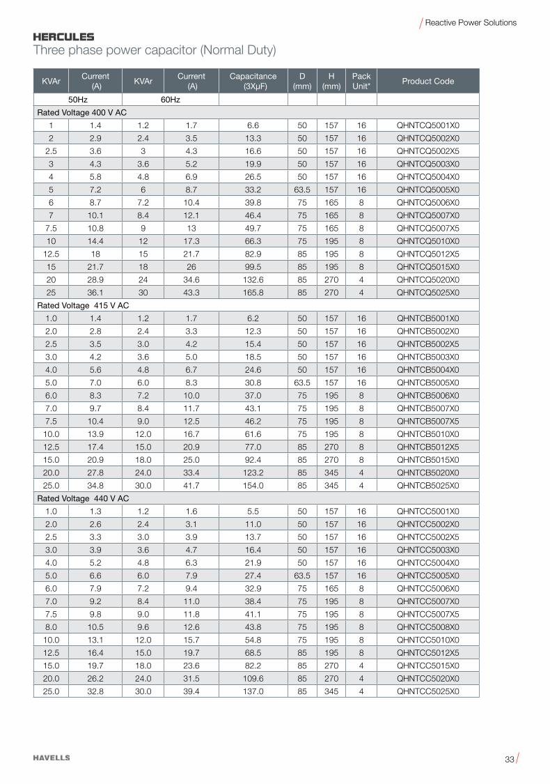
Hercules Three Phase PFC Capacitors - Normal DutyNonPCB,SoftResinImpregnated•StackedWinding•TrippleSafetySystem
GeneralHercules capacitors are MPP (metalized polypropylene) capacitors from
Havells which have been used for PFC applications for more than 7 years
The power range varies from 1.0 to 30.0 KVAr.
The Hercules capacitor is used for power factor correction in industrial applications.
Applications•PowerFactorCorrection(PFC)•Automaticcapacitorbanks•FixedPFCapplications,e.g.motorcompensation
•DetunedPFCsystems•DynamicPFCsystems•FilterApplication
Features•Compactdesignincylindricalaluminumcanwithstud•Stackedwinding•MPPtechnology
•Voltagerange400…525V•Outputrange1.0…30.0KVAr
Electrical•Longlifeexpectancyofupto100000hours•Max.transientinrushcurrenthandlingcapabilityis200xIR
Mechanical and maintenance•Reducedmountingcosts•Easyinstallationandconnection•Lowweightandcompactvolume•Maintenance-free
Safety•Self-healing•Overpressuredisconnector•Shockhazardprotectedoptimizedcapacitorsafetyterminalsabove6KVAr
TORRENT

31
Reactive Power Solutions
-Softresinimpregnated•Stackedwinding•TrippleSafetySystem
Parameter Unit Hercules
Reference Standard IS 13340 / IEC 60831
Power (Rated Capacitance) Qn 1 – 30 KVAr
Tolerance 0 –10%
Connection Delta
Rated voltage VR 400 – 525
Rated Frequency fR 50 / 60 Hz
Max. Ratings
Max. Permisible Voltage Vmax.
VR+10%(upto8hdaily)VR+15%(upto30mindaily)VR+20%(upto5mindaily)VR+30%(upto1mindaily)
Max. Permisible Current Imax.Up to 1.3 x IR (up to 1.5 x IR incl. combined
effects of harmonics, over voltages and capacitance)
Max. Transient Inrush Current Handling Capacity IS up to 200 x IRTest Data
AC Test Voltage Terminal to Terminal VTT 2.15 x UN, 2 Sec.
Insulation Voltage Between Terminal & Container VTC 3600 V AC, 2 Sec.
Losses:
– Dielectric <0.2W/KVAr
– Total* <0.4W/KVAr
Climatic Category
Ambient Temperature 0 C-25 / D; max. temp. 550 C; max mean 24h = 45 0C;max. mean 1 year = 35 0C; lowest temp. = -25 0C
Max. humidity Hrel 95%
Max. Permisible Altitute 4000 M above sea level
Design Data
Case Material / Shape Aluminium / Cylindrical
Dimensions According to specification table page no. 33, 34
Dielectric Polypropylene Film
Impregnation Soft Resin
Fixing Threaded Bolt M8 / M12
Max. Tourque for Fixing Nm 4 Nm / 10 Nm
Mounting PositionUpright. Horizontal mounting with additional head support possible.
Terminals Upto 5KVAr fast on and above clamp
Degree of Protection Safety IP20 optional IP54
Max. Tourque for Connection Terminals (6 KVAr and above) Nm 2.5 Nm
Safety
Mechnical Safety Tear of fuses, overpressure disconnector
Discharge Device Resister
Discharge Device Time Sec. ≤60 Sec (50 V)
Cooling Natural or Forced
Max. Switching Operations Max. 5000 Nos. Per Year
Ordering Code QHNTC*
* Without Discharge Resister
Note:
1. It should be noted that presence of harmonics produce over voltage & over current on capacitors. Resonance may cause serious damage to capacitor if a significant level of total harmonic distortion level exists for voltage or current. In such cases, series reactors must be considered.
2. Operatingtemperatureclass:Inaccordancewiththereferencestandards,thesetemperaturesarethosemeasuredonthesurfaceonthecapacitor.
TORRENT

32
Reactive Power Solutions
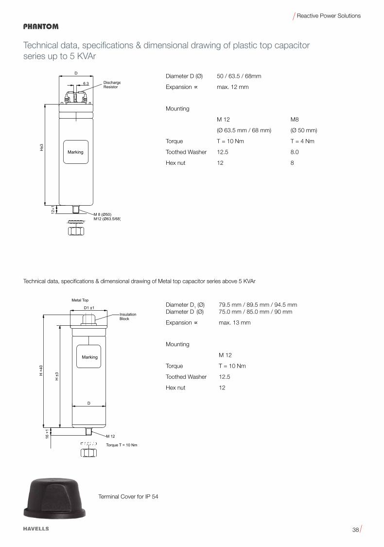
Diameter D1 (Ø) 79.5 mm / 89.5 mm / 94.5 mm Diameter D (Ø) 75.0 mm / 85.0 mm / 90 mm
Expansion µ max. 13 mm
Mounting
M 12
Torque T = 10 Nm
ToothedWasher 12.5
Hex nut 12
Terminal Cover for IP 54
Diameter D (Ø) 50 / 63.5 / 68mm
Expansion µ max. 12 mm
Mounting
M 12 M8
(Ø 63.5 mm / 68 mm) (Ø 50 mm)
Torque T = 10 Nm T = 4 Nm
ToothedWasher 12.5 8.0
Hex nut 12 8
Technical data, specifications & dimensional drawing of plastic top capacitor series up to 5 KVAr
Technical data, specifications & dimensional drawing of Metal top capacitor series above 5 KVAr
12+
1
TORRENT
33
Reactive Power Solutions
KVArCurrent
(A)KVAr
Current (A)
Capacitance (3XµF)
D(mm)
H(mm)
Pack Unit*
Product Code
50Hz 60Hz
Rated Voltage 400 V AC
1 1.4 1.2 1.7 6.6 50 157 16 QHNTCQ5001X0
2 2.9 2.4 3.5 13.3 50 157 16 QHNTCQ5002X0
2.5 3.6 3 4.3 16.6 50 157 16 QHNTCQ5002X5
3 4.3 3.6 5.2 19.9 50 157 16 QHNTCQ5003X0
4 5.8 4.8 6.9 26.5 50 157 16 QHNTCQ5004X0
5 7.2 6 8.7 33.2 63.5 157 16 QHNTCQ5005X0
6 8.7 7.2 10.4 39.8 75 165 8 QHNTCQ5006X0
7 10.1 8.4 12.1 46.4 75 165 8 QHNTCQ5007X0
7.5 10.8 9 13 49.7 75 165 8 QHNTCQ5007X5
10 14.4 12 17.3 66.3 75 195 8 QHNTCQ5010X0
12.5 18 15 21.7 82.9 85 195 8 QHNTCQ5012X5
15 21.7 18 26 99.5 85 195 8 QHNTCQ5015X0
20 28.9 24 34.6 132.6 85 270 4 QHNTCQ5020X0
25 36.1 30 43.3 165.8 85 270 4 QHNTCQ5025X0
Rated Voltage 415 V AC
1.0 1.4 1.2 1.7 6.2 50 157 16 QHNTCB5001X0
2.0 2.8 2.4 3.3 12.3 50 157 16 QHNTCB5002X0
2.5 3.5 3.0 4.2 15.4 50 157 16 QHNTCB5002X5
3.0 4.2 3.6 5.0 18.5 50 157 16 QHNTCB5003X0
4.0 5.6 4.8 6.7 24.6 50 157 16 QHNTCB5004X0
5.0 7.0 6.0 8.3 30.8 63.5 157 16 QHNTCB5005X0
6.0 8.3 7.2 10.0 37.0 75 195 8 QHNTCB5006X0
7.0 9.7 8.4 11.7 43.1 75 195 8 QHNTCB5007X0
7.5 10.4 9.0 12.5 46.2 75 195 8 QHNTCB5007X5
10.0 13.9 12.0 16.7 61.6 75 195 8 QHNTCB5010X0
12.5 17.4 15.0 20.9 77.0 85 270 8 QHNTCB5012X5
15.0 20.9 18.0 25.0 92.4 85 270 8 QHNTCB5015X0
20.0 27.8 24.0 33.4 123.2 85 345 4 QHNTCB5020X0
25.0 34.8 30.0 41.7 154.0 85 345 4 QHNTCB5025X0
Rated Voltage 440 V AC
1.0 1.3 1.2 1.6 5.5 50 157 16 QHNTCC5001X0
2.0 2.6 2.4 3.1 11.0 50 157 16 QHNTCC5002X0
2.5 3.3 3.0 3.9 13.7 50 157 16 QHNTCC5002X5
3.0 3.9 3.6 4.7 16.4 50 157 16 QHNTCC5003X0
4.0 5.2 4.8 6.3 21.9 50 157 16 QHNTCC5004X0
5.0 6.6 6.0 7.9 27.4 63.5 157 16 QHNTCC5005X0
6.0 7.9 7.2 9.4 32.9 75 165 8 QHNTCC5006X0
7.0 9.2 8.4 11.0 38.4 75 195 8 QHNTCC5007X0
7.5 9.8 9.0 11.8 41.1 75 195 8 QHNTCC5007X5
8.0 10.5 9.6 12.6 43.8 75 195 8 QHNTCC5008X0
10.0 13.1 12.0 15.7 54.8 75 195 8 QHNTCC5010X0
12.5 16.4 15.0 19.7 68.5 85 195 8 QHNTCC5012X5
15.0 19.7 18.0 23.6 82.2 85 270 4 QHNTCC5015X0
20.0 26.2 24.0 31.5 109.6 85 270 4 QHNTCC5020X0
25.0 32.8 30.0 39.4 137.0 85 345 4 QHNTCC5025X0
Three phase power capacitor (Normal Duty)

34
Reactive Power Solutions
*Packing units for capacitors equal minimum order quantity. Orders will be rounded up to packing unit or multiple thereof. Note:Customized products available upon request. Minimum Order Quantity 50 Nos. All Hercules –type capacitors may be used for 60Hz, the output will be 1.2 times higherReplace X with E for export orders.
KVArCurrent
(A)KVAr
Current (A)
Capacitance (3XµF)
D(mm)
H(mm)
Pack Unit*
Product Code
50Hz 60Hz
Rated Voltage 480 V AC
1.0 1.2 1.2 1.4 4.6 50 157 16 QHNTCD5001X0
2.0 2.4 2.4 2.9 9.2 50 157 16 QHNTCD5002X0
2.5 3.0 3.0 3.6 11.5 50 157 16 QHNTCD5002X5
3.0 3.6 3.6 4.3 13.8 50 157 16 QHNTCD5003X0
4.0 4.8 4.8 5.8 18.4 63.5 157 16 QHNTCD5004X0
5.0 6.0 6.0 7.2 23.0 63.5 157 16 QHNTCD5005X0
6.0 7.2 7.2 8.7 27.6 75 165 8 QHNTCD5006X0
7.0 8.4 8.4 10.1 32.2 75 195 8 QHNTCD5007X0
7.5 9.0 9.0 10.8 34.5 75 195 8 QHNTCD5007X5
8.0 9.6 9.6 11.5 36.8 75 195 8 QHNTCD5008X0
10.0 12.0 12.0 14.4 46.0 85 270 8 QHNTCD5010X0
12.5 15.0 15.0 18.0 57.6 85 270 8 QHNTCD5012X5
15.0 18.0 18.0 21.7 69.1 85 270 4 QHNTCD5015X0
20.0 24.1 24.0 28.9 92.1 90 270 4 QHNTCD5020X0
25.0 30.1 30.0 36.1 115.1 85 345 4 QHNTCD5025X0
30.0 36.1 36.0 43.3 138.1 90 345 4 QHNTCD5030X0
Rated Voltage 525 V AC
1.0 1.1 1.2 1.3 3.8 50 157 16 QHNTCF5001X0
2.0 2.2 2.4 2.6 7.7 50 157 16 QHNTCF5002X0
2.5 2.7 3.0 3.3 9.6 50 157 16 QHNTCF5002X5
3.0 3.3 3.6 4.0 11.5 50 157 16 QHNTCF5003X0
4.0 4.4 4.8 5.3 15.4 63.5 157 16 QHNTCF5004X0
5.0 5.5 6.0 6.6 19.2 63.5 157 16 QHNTCF5005X0
6.0 6.6 7.2 7.9 23.1 75 195 8 QHNTCF5006X0
7.0 7.7 8.4 9.2 26.9 75 195 8 QHNTCF5007X0
7.5 8.2 9.0 9.9 28.9 75 195 8 QHNTCF5007X5
8.0 8.8 9.6 10.6 30.8 75 195 8 QHNTCF5008X0
10.0 11.0 12.0 13.2 38.5 75 195 8 QHNTCF5010X0
12.5 13.7 15.0 16.5 48.1 85 195 8 QHNTCF5012X5
15.0 16.5 18.0 19.8 57.7 85 270 8 QHNTCF5015X0
20.0 22.0 24.0 26.4 77.0 85 270 4 QHNTCF5020X0
25.0 27.5 30.0 33.0 96.2 90 270 4 QHNTCF5025X0
Three phase power capacitor (Normal Duty)
35
Reactive Power Solutions

36
Reactive Power Solutions
Phantom Three Phase PFC Capacitors (Heavy Duty)NonPCBSoftResinImpregnated•StackedWinding•TrippleSafetySystem
General
Phantom capacitors are MPP (metalized polypropylene) capacitors from Havells which have been used for PFC applications for more than 7 years. The power range varies from 1.0 to 25.0 KVAr. The Phantom capacitor is used for power factor correction in industrial applications where some amount of harmonics are presents.
Applications•PowerFactorCorrection(PFC)•Automaticcapacitorbanks•FixedPFCapplications,e.g.motorcompensation•DetunedPFCsystems•DynamicPFCsystems•FilterApplication
Features•Compactdesignincylindricalaluminumcanwithstud•Stackedwinding•MPPtechnology•Voltagerange400…525V•Outputrange1.0…25.0KVAr
Electrical•Longlifeexpectancyofupto130000hours•Max.transientinrushcurrenthandlingcapabilityis250xIR
Mechanical and maintenance•Reducedmountingcosts•Easyinstallationandconnection•Lowweightandcompactvolume•Maintenance-free
Safety •Self-healing•Overpressuredisconnector•Shockhazardprotectedoptimizedcapacitorsafetyterminalsabove6KVAr
Cylindrical PFC Capacitor

37
Reactive Power Solutions
-Softresinimpregnated•Stackedwinding•TrippleSafetySystem
Parameter Unit Phantom
Reference Standard IS 13340 / IEC 60831
Power (Rated Capacitance) Qn 1 – 25 KVAr
Tolerance 0 –10%
Connection Delta
Rated voltage VR 400 – 525
Rated Frequency fR 50 / 60 Hz
Max. Ratings
Max. Permisible Voltage Vmax.
VR+10%(upto8hdaily)VR+15%(upto30mindaily)VR+20%(upto5mindaily)VR+30%(upto1mindaily)
Max. Permisible Current Imax.Up to 1.3 x IR (up to 1.5 x IR incl. combined effects of harmonics, over voltages and capacitance)
Max. Transient Inrush Current Handling Capacity IS up to 250 x IRTest Data
AC Test Voltage Terminal to Terminal VTT 2.15 x UN, 2 Sec.
Insulation Voltage Between Terminal & Container VTC 3600 V AC, 2 Sec.
Losses:
– Dielectric <0.2W/KVAr
– Total* <0.4W/KVAr
Climatic Category
Ambient Temperature 0 C-25 / D; max. temp. 550 C; max mean 24h = 45 0C;max. mean 1 year = 35 0C; lowest temp. = -25 0C
Max. humidity Hrel 95%
Max. Permisible Altitute 4000 M above sea level
Design Data
Case Material / Shape Aluminium / Cylindrical
Dimensions According to Specification Table Page No. 39, 40
Dielectric Polypropylene Film
Impregnation Soft Resin
Fixing Threaded Bolt M8 / M12
Max. Tourque for Fixing Nm 4 Nm / 10 Nm
Mounting PositionUpright. Horizontal mounting with additional head support Possible.
Terminals Upto 5KVAr fast on and above clamp
Degree of Protection Safety IP20 optional IP54
Max. Tourque for Connection Terminals (6 KVAr and above) Nm 2.5 Nm
Safety
Mechnical Safety Tear of fuses, overpressure disconnector
Discharge Device Resister
Discharge Device Time Sec. ≤60 Sec (50 V)
Cooling Natural or Forced
Max. Switching Operations Max. 5000 Nos. Per Year
Ordering Code QHHTC*
* Without Discharge Resister
Note:
1. It should be noted that presence of harmonics produce over voltage & over current on capacitors. Resonance may cause serious damage to capacitor if a significant level of total harmonic distortion level exists for voltage or current. In such cases, series reactors must be considered.
2. Operatingtemperatureclass:Inaccordancewiththereferencestandards,thesetemperaturesarethosemeasuredonthesurfaceonthecapacitor.
38
Reactive Power Solutions
Technical data, specifications & dimensional drawing of plastic top capacitor series up to 5 KVAr
Technical data, specifications & dimensional drawing of Metal top capacitor series above 5 KVAr
Diameter D1 (Ø) 79.5 mm / 89.5 mm / 94.5 mm Diameter D (Ø) 75.0 mm / 85.0 mm / 90 mm
Expansion µ max. 13 mm
Mounting
M 12
Torque T = 10 Nm
ToothedWasher 12.5
Hex nut 12
Diameter D (Ø) 50 / 63.5 / 68mm
Expansion µ max. 12 mm
Mounting
M 12 M8
(Ø 63.5 mm / 68 mm) (Ø 50 mm)
Torque T = 10 Nm T = 4 Nm
ToothedWasher 12.5 8.0
Hex nut 12 8
Terminal Cover for IP 54
12+
1

39
Reactive Power Solutions
KVArCurrent
(A)KVAr
Current (A)
Capacitance (3XµF)
D(mm)
H(mm)
Pack Unit*
Product Code
50Hz 60Hz
Rated Voltage 400 V AC
1 1.4 1.2 1.7 6.6 50 157 16 QHHTCQ5001X0
2 2.9 2.4 3.5 13.3 50 157 16 QHHTCQ5002X0
2.5 3.6 3 4.3 16.6 50 157 16 QHHTCQ5002X5
3 4.3 3.6 5.2 19.9 63.5 157 16 QHHTCQ5003X0
4 5.8 4.8 6.9 26.5 63.5 157 16 QHHTCQ5004X0
5 7.2 6 8.7 33.2 63.5 157 16 QHHTCQ5005X0
6 8.7 7.2 10.4 39.8 75 195 8 QHHTCQ5006X0
7 10.1 8.4 12.1 46.4 75 195 8 QHHTCQ5007X0
7.5 10.8 9 13 49.7 75 195 8 QHHTCQ5007X5
8.0 11.5 9.6 13.9 53.0 75 195 8 QHHTCQ5008X0
10 14.4 12 17.3 66.3 85 270 8 QHHTCQ5010X0
12.5 18 15 21.7 82.9 85 270 8 QHHTCQ5012X5
15 21.7 18 26 99.5 85 270 8 QHHTCQ5015X0
20 28.9 24 34.6 132.6 85 345 4 QHHTCQ5020X0
25 36.1 30 43.3 165.8 85 345 4 QHHTCQ5025X0
Rated Voltage 415 V AC
1 1.4 1.2 1.7 6.2 50 157 16 QHHTCB5001X0
2 2.8 2.4 3.3 12.3 50 157 16 QHHTCB5002X0
2.5 3.5 3 4.2 15.4 50 157 16 QHHTCB5002X5
3 4.2 3.6 5.0 18.5 63.5 157 16 QHHTCB5003X0
4 5.6 4.8 6.7 24.6 63.5 157 16 QHHTCB5004X0
5 7.0 6 8.3 30.8 63.5 157 16 QHHTCB5005X0
6 8.3 7.2 10.0 37.0 75 195 8 QHHTCB5006X0
7 9.7 8.4 11.7 43.1 75 195 8 QHHTCB5007X0
7.5 10.4 9 12.5 46.2 85 195 8 QHHTCB5007X5
8.0 11.1 9.6 13.4 49.3 85 195 8 QHHTCB5008X0
10 13.9 12 16.7 61.6 85 270 4 QHHTCB5010X0
12.5 17.4 15 20.9 77.0 85 270 4 QHHTCB5012X5
15 20.9 18 25.0 92.4 85 270 4 QHHTCB5015X0
20 27.8 24 33.4 123.2 85 345 4 QHHTCB5020X0
25 34.8 30.0 41.7 154.0 85 345 4 QHHTCB5025X0
Rated Voltage 440 V AC
1 1.3 1.2 1.6 5.5 50 157 16 QHHTCC5001X0
2 2.6 2.4 3.1 11.0 50 157 16 QHHTCC5002X0
2.5 3.3 3 3.9 13.7 50 157 16 QHHTCC5002X5
3 3.9 3.6 4.7 16.4 63.5 157 16 QHHTCC5003X0
4 5.2 4.8 6.3 21.9 63.5 157 16 QHHTCC5004X0
5 6.6 6 7.9 27.4 68 157 16 QHHTCC5005X0
6 7.9 7.2 9.4 32.9 75 195 8 QHHTCC5006X0
7 9.2 8.4 11.0 38.4 75 195 8 QHHTCC5007X0
7.5 9.8 9 11.8 41.1 75 195 8 QHHTCC5007X5
8.0 10.5 9.6 12.6 43.8 75 195 8 QHHTCC5008X0
10 13.1 12 15.7 54.8 85 270 8 QHHTCC5010X0
12.5 16.4 15 19.7 68.5 85 270 4 QHHTCC5012X5
15 19.7 18 23.6 82.2 85 270 4 QHHTCC5015X0
20 26.2 24 31.5 109.6 85 345 4 QHHTCC5020X0
25 32.8 30.0 39.4 137.0 90 345 4 QHHTCC5025X0
Three phase power capacitor (Heavy Duty)

40
Reactive Power Solutions
*Packing units for capacitors equal minimum order quantity. Orders will be rounded up to packing unit or multiple thereof. Note:Customized products available upon request. Minimum Order Quantity 50 Nos. All Phantom – Type capacitors may be used for 60Hz, the output will be 1.2 times higherReplace X with E for export orders.
Three phase power capacitor (heavy duty)
KVArCurrent
(A)KVAr
Current (A)
Capacitance (3XµF)
D(mm)
H(mm)
Pack Unit*
Product Code
50Hz 60Hz
Rated Voltage 480 V AC
1 1.2 1.2 1.4 4.6 50 157 16 QHHTCD5001X0
2 2.4 2.4 2.9 9.2 50 157 16 QHHTCD5002X0
2.5 3.0 3 3.6 11.5 50 157 16 QHHTCD5002X5
3 3.6 3.6 4.3 13.8 63.5 157 16 QHHTCD5003X0
4 4.8 4.8 5.8 18.4 63.5 157 16 QHHTCD5004X0
5 6.0 6 7.2 23.0 68 157 16 QHHTCD5005X0
6 7.2 7.2 8.7 27.6 75 195 8 QHHTCD5006X0
7 8.4 8.4 10.1 32.2 75 195 8 QHHTCD5007X0
7.5 9.0 9 10.8 34.5 75 195 8 QHHTCD5007X5
8.0 9.6 9.6 11.5 36.8 75 195 8 QHHTCD5008X0
10 12.0 12 14.4 46.0 85 270 8 QHHTCD5010X0
12.5 15.0 15 18.0 57.6 85 270 4 QHHTCD5012X5
15 18.0 18 21.7 69.1 85 270 4 QHHTCD5015X0
20 24.1 24 28.9 92.1 85 345 4 QHHTCD5020X0
25 30.1 30.0 36.1 115.1 90 345 4 QHHTCD5025X0
Rated Voltage 525 V AC
1 1.1 1.2 1.3 3.8 50 157 16 QHHTCF5001X0
2 2.2 2.4 2.6 7.7 50 157 16 QHHTCF5002X0
2.5 2.7 3 3.3 9.6 50 157 16 QHHTCF5002X5
3 3.3 3.6 4.0 11.5 63.5 157 16 QHHTCF5003X0
4 4.4 4.8 5.3 15.4 63.5 157 16 QHHTCF5004X0
5 5.5 6 6.6 19.2 63.5 187 16 QHHTCF5005X0
6 6.6 7.2 7.9 23.1 75 195 8 QHHTCF5006X0
7 7.7 8.4 9.2 26.9 75 195 8 QHHTCF5007X0
7.5 8.2 9 9.9 28.9 75 195 8 QHHTCF5007X5
8.0 8.8 9.6 10.6 30.8 85 195 8 QHHTCF5008X0
10 11.0 12 13.2 38.5 85 270 8 QHHTCF5010X0
12.5 13.7 15 16.5 48.1 85 270 4 QHHTCF5012X5
15 16.5 18 19.8 57.7 85 270 4 QHHTCF5015X0
20 22.0 24 26.4 77.0 90 270 4 QHHTCF5020X0
25 27.5 30.0 33.0 96.2 90 345 4 QHHTCF5025X0

41
Reactive Power Solutions

42
Reactive Power Solutions
Cylindrical PFC Capacitor
Agri Boost Three Phase PFC CapacitorsNonPCBSoftResinImpregnated•StackedWinding•TrippleSafetySystem
General Agri Boost capacitors are MPP (metalized polypropylene) capacitors from Havells which have been used for PFC applications for more than 7 years. The power range varies from 1.0 to 15.0 KVAr.
The Agri Boost capacitor is used for power factor correction.
Applications•AgricultureUse
Features•Compactdesignincylindricalaluminumcanwithstud•Stackedwinding•MPPtechnology•Voltagerange415V •Outputrange1.0…15.0KVAr
Electrical•Longlifeexpectancyofupto100000hours•Max.transientinrushcurrenthandlingcapabilityis200xIR
Mechanical and maintenance•Reducedmountingcosts•Easyinstallationandconnection•Lowweightandcompactvolume•Maintenance-free

43
Reactive Power Solutions
-Softresinimpregnated•Stackedwinding•TrippleSafetySystem
Parameter Unit Agri Boost
Reference Standard IS 13340
Power (Rated Capacitance) Qn 1 – 15 KVAr
Tolerance 0 –10%
Connection Delta
Rated voltage VR 415 – 440
Rated Frequency fR 50 / 60 Hz
Max. Ratings
Max. Permisible Voltage Vmax.
VR+10%(upto8hdaily)VR+15%(upto30mindaily)VR+20%(upto5mindaily)VR+30%(upto1mindaily)
Max. Permisible Current Imax.Up to 1.3 x IR (up to 1.5 x IR incl. combined effects of harmonics, over voltages and capacitance)
Max. Transient Inrush Current Handling Capacity IS up to 200 x IRTest Data
AC Test Voltage Terminal to Terminal VTT 1.75 x UN, 2 Sec.
Insulation Voltage Between Terminal & Container VTC 3600 V AC, 2 Sec.
Losses:
– Dielectric <0.2W/KVAr
– Total <0.4W/KVAr
Climatic Category
Ambient Temperature 0 C-25 / D; max. temp. 550 C; max mean 24h = 45 0C;max. mean 1 year = 35 0C; lowest temp. = -25 0C
Max. humidity Hrel 95%
Max. Permisible Altitute 4000 M above sea level
Mean Life Expectancy tLD (co) 100000 Hrs
Design Data
Case Material / Shape Aluminium / Cylindrical
Dimensions According to Specification Table Page No. 44
Dielectric Polypropylene Film
Impregnation Soft Resin
Fixing Threaded Bolt M8 / M12
Mounting PositionUpright. Horizontal mounting with additional head support Possible.
Terminals WireTerminal
Degree of Protection Safety IP54
Max. Tourque for Connection Terminals (6 KVAr and above) Nm
Safety
Mechnical Safety Tear of fuses, overpressure disconnector
Discharge Device Resister
Discharge Device Time Sec. ≤60 Sec (50 V)
Cooling Natural or Forced
Max. Switching Operations Max. 5000 Nos. Per Year
Ordering Code QHATC*
Note:
1. It should be noted that presence of harmonics produce over voltage & over current on capacitors. Resonance may cause serious damage to capacitor if a significant level of total harmonic distortion level exists for voltage or current. In such cases, series reactors must be considered.
2. Operatingtemperatureclass:Inaccordancewiththereferencestandards,thesetemperaturesarethosemeasuredonthesurfaceonthecapacitor.

44
Reactive Power Solutions
Three phase power capacitor
KVArCurrent
(A)KVAr
Current (A)
Capacitance (3XµF)
D(mm)
H(mm)
Pack Unit*
Product Code
50Hz 60Hz
Rated Voltage 415 V AC (Normal Duty)
1 1.4 1.2 1.7 6.2 40 157 16 QHATCB5001X0
2 2.8 2.4 3.3 12.3 40 157 16 QHATCB5002X0
3 4.2 3.6 5 18.5 50 157 16 QHATCB5003X0
4 5.6 4.8 6.7 24.6 50 157 16 QHATCB5004X0
5 7 6 8.3 30.8 50 157 16 QHATCB5005X0
6 8.3 7.2 10 37 63.5 157 16 QHATCB5006X0
7 9.7 8.4 11.7 43.1 63.5 157 16 QHATCB5007X0
7.5 10.4 9 12.5 46.2 63.5 157 16 QHATCB5007X5
8 11.1 9.6 13.4 49.3 63.5 157 16 QHATCB5008X0
10 13.9 12 16.7 61.6 68 192 16 QHATCB5010X0
12.5 17.4 15 20.9 77 85 192 8 QHATCB5012X5
15 20.9 18 25 92.4 85 192 8 QHATCB5015X0
Rated Voltage 415 V AC (Heavy Duty)
1 1.4 1.2 1.7 6.2 40 157 16 QHITCB5001X0
2 2.8 2.4 3.3 12.3 50 157 16 QHITCB5002X0
3 4.2 3.6 5 18.5 63.5 157 16 QHITCB5003X0
4 5.6 4.8 6.7 24.6 63.5 157 16 QHITCB5004X0
5 7 6 8.3 30.8 68 157 16 QHITCB5005X0
6 8.3 7.2 10 37 63 192 16 QHITCB5006X0
7 9.7 8.4 11.7 43.1 68 192 16 QHITCB5007X0
7.5 10.4 9 12.5 46.2 68 192 16 QHITCB5007X5
8 11.1 9.6 13.4 49.3 75 192 8 QHITCB5008X0
10 13.9 12 16.7 61.6 85 192 8 QHITCB5010X0
12.5 17.4 15 20.9 77 85 270 4 QHITCB5012X5
15 20.9 18 25 92.4 85 270 4 QHITCB5015X0
*Packing units for capacitors equal minimum order quantity. Orders will be rounded up to packing unit or multiple thereof. Note:Customized products available upon request. Minimum Order Quantity 50 Nos. All Agri Boost – Type capacitors may be used for 60Hz, the output will be 1.2 times higher

45
Reactive Power Solutions
Havells easy way to perform energy consumption studies – Harmonic AnalysisFor finding energy waste in commercial, factory buildings and equipment through energy consumption studies and electrical load analysis and perform power quality logging and analysis according to IEEE 519 – 1992 IEEE Recommended Practices & Requirements for Harmonic Control in Electrical Power System.
Electronicequipmentstudymeasuresvirtuallyeverypowersystemparameter:voltage,current,frequency,power,energyconsumption,cos f or power factor, unbalance, and harmonics and inter-harmonics.
Measureandrecordpower(W),VAandVARs.
The System-Monitor overview screen gives instant insight into whether the voltage, harmonics, frequency, and the number of dips and swells fall outside the set limits.provides analysis of user-selectable parameters to find intermittent problems or relate PQ issues to other phenomena/events.
Graph shows voltage and current unbalance, and helps verify connections
Load studies and energy assessments
• Monitor maximum power demand over user-defined averaging periods
• Demonstrate the benefit of efficiency improvements withenergy consumption tests
• Measureharmonicdistortioncausedbyelectronicloads• Analyze reliability problems by capturing voltage dips and
swells from load switching• Showcaseeventslikedipsandswells,interruptionsandrapid
voltage changes, based upon ½ cycle rms values.• Meets the stringent 600 V CAT IV, 1000 V CAT III safety
standard required for measurements at service entrance
Analyze every parameter on display
For queries & price offer on harmonic analysis, please e-mail: [email protected] or contact our nearest sales offices.
customize measurement selections and provides analysis of user-selectable parameters to find intermittent problems or relate PQ issues to other phenomena/events.
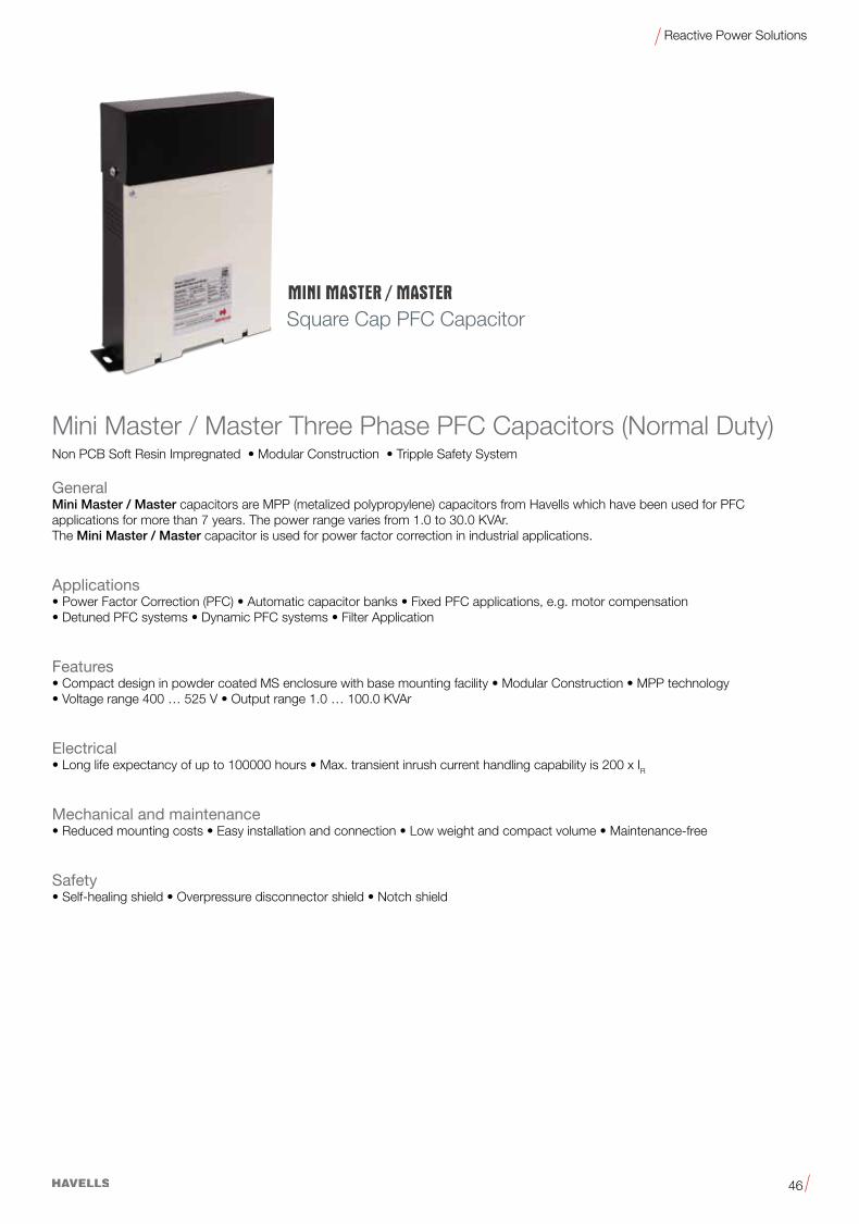
46
Reactive Power Solutions
Square Cap PFC Capacitor
Mini Master / Master Three Phase PFC Capacitors (Normal Duty)NonPCBSoftResinImpregnated•ModularConstruction•TrippleSafetySystem
General Mini Master / Master capacitors are MPP (metalized polypropylene) capacitors from Havells which have been used for PFC applications for more than 7 years. The power range varies from 1.0 to 30.0 KVAr. The Mini Master / Master capacitor is used for power factor correction in industrial applications.
Applications•PowerFactorCorrection(PFC)•Automaticcapacitorbanks•FixedPFCapplications,e.g.motorcompensation•DetunedPFCsystems•DynamicPFCsystems•FilterApplication
Features•CompactdesigninpowdercoatedMSenclosurewithbasemountingfacility•ModularConstruction•MPPtechnology•Voltagerange400…525V•Outputrange1.0…100.0KVAr
Electrical•Longlifeexpectancyofupto100000hours•Max.transientinrushcurrenthandlingcapabilityis200xIR
Mechanical and maintenance•Reducedmountingcosts•Easyinstallationandconnection•Lowweightandcompactvolume•Maintenance-free
Safety•Self-healingshield•Overpressuredisconnectorshield•Notchshield
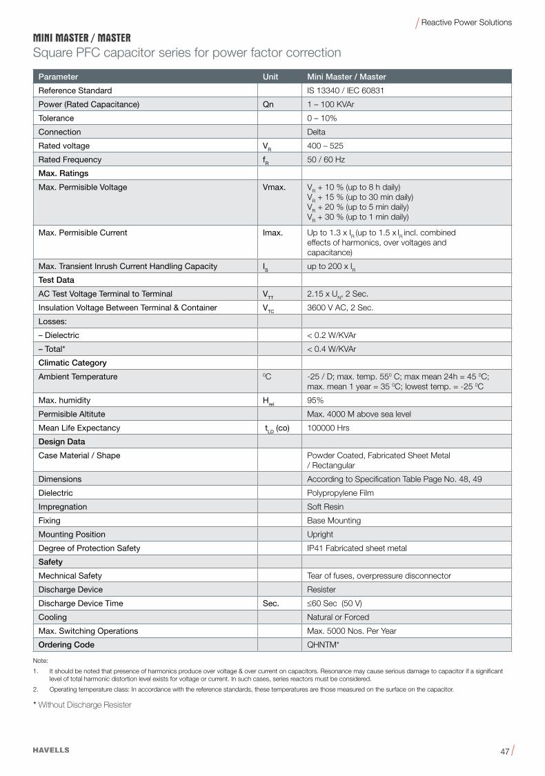
47
Reactive Power Solutions
Square PFC capacitor series for power factor correction
* Without Discharge Resister
Parameter Unit Mini Master / Master
Reference Standard IS 13340 / IEC 60831
Power (Rated Capacitance) Qn 1 – 100 KVAr
Tolerance 0 – 10%
Connection Delta
Rated voltage VR 400 – 525
Rated Frequency fR 50 / 60 Hz
Max. Ratings
Max. Permisible Voltage Vmax. VR+10%(upto8hdaily)VR+15%(upto30mindaily)VR+20%(upto5mindaily)VR+30%(upto1mindaily)
Max. Permisible Current Imax. Up to 1.3 x IR (up to 1.5 x IR incl. combined
effects of harmonics, over voltages and capacitance)
Max. Transient Inrush Current Handling Capacity IS up to 200 x IRTest Data
AC Test Voltage Terminal to Terminal VTT 2.15 x UN, 2 Sec.
Insulation Voltage Between Terminal & Container VTC 3600 V AC, 2 Sec.
Losses:
– Dielectric <0.2W/KVAr
– Total* <0.4W/KVAr
Climatic Category
Ambient Temperature 0C -25 / D; max. temp. 550 C; max mean 24h = 45 0C;max. mean 1 year = 35 0C; lowest temp. = -25 0C
Max. humidity Hrel 95%
Permisible Altitute Max. 4000 M above sea level
Mean Life Expectancy tLD (co) 100000 Hrs
Design Data
Case Material / Shape Powder Coated, Fabricated Sheet Metal / Rectangular
Dimensions According to Specification Table Page No. 48, 49
Dielectric Polypropylene Film
Impregnation Soft Resin
Fixing Base Mounting
Mounting Position Upright
Degree of Protection Safety IP41 Fabricated sheet metal
Safety
Mechnical Safety Tear of fuses, overpressure disconnector
Discharge Device Resister
Discharge Device Time Sec. ≤60 Sec (50 V)
Cooling Natural or Forced
Max. Switching Operations Max. 5000 Nos. Per Year
Ordering Code QHNTM*
Note:
1. It should be noted that presence of harmonics produce over voltage & over current on capacitors. Resonance may cause serious damage to capacitor if a significant level of total harmonic distortion level exists for voltage or current. In such cases, series reactors must be considered.
2. Operatingtemperatureclass:Inaccordancewiththereferencestandards,thesetemperaturesarethosemeasuredonthesurfaceonthecapacitor.

48
Reactive Power Solutions
Frame Size A1 A2 A3 D H
B00 120 132 144 50 180
B0 155 167 179 60 225
B1 195 217 239 75 290
B2 220 242 264 80 290
B3 220 242 264 160 300
Technical Data, Specifications & Dimensional Drawing
Dimensions in (mm)
KVAr Bank Rating A1 A2 A3 D H K
50 25 X 2 nos 220 242 264 320 325 410
75 25 X 3 nos 220 242 264 480 325 570
100 25 X 4 nos 220 242 264 640 390 725
Dimensions in (mm)
D A1 A2
A3
K
H
H
A1
A3
A2D

49
Reactive Power Solutions
*Packing units for capacitors equal minimum order quantity. Orders will be rounded up to packing unit or multiple thereof.
Note:QHNTW is with wire terminal & QHNTM is with bolt terminal.Customized products available upon request. Minimum Order Quantity 50 Nos. All Minimaster & Master – Type capacitors may be used for 60Hz, the output will be 1.2 times higher
KVArCurrent
(A)KVAr
Current (A)
Capacitance (3XµF)
Frame SizePack Unit*
Product Code
50Hz 60Hz
Rated Voltage 415 V AC
1 1.4 1.2 1.7 6.2 B00 30 QHNTMB5001X0
2 2.8 2.4 3.3 12.3 B00 30 QHNTMB5002X0
3 4.2 3.6 5 18.5 B0 24 QHNTMB5003X0
4 5.6 4.8 6.7 24.6 B0 24 QHNTMB5004X0
5 7 6 8.3 30.8 B0 24 QHNTMB5005X0
6 8.3 7.2 10 37 B1 1 QHNTMB5006X0
7 9.7 8.4 11.7 43.1 B1 1 QHNTMB5007X0
7.5 10.4 9 12.5 46.2 B1 1 QHNTMB5007X5
8 11.1 9.6 13.4 49.3 B1 1 QHNTMB5008X0
10 13.9 12 16.7 61.6 B1 1 QHNTMB5010X0
12.5 17.4 15 20.9 77 B2 1 QHNTMB5012X5
15 20.9 18 25 92.4 B2 1 QHNTMB5015X0
20 27.8 24 33.4 (2 X 61.6) B3 1 QHNTMB5020X0
25 34.8 30 41.7 (2 X 77.0) B3 1 QHNTMB5025X0
30 41.7 36 50.1 (2 X 92.4) B3 1 QHNTCB5030X0
50 69.6 60 83.5 (4 X 77.0) 25 X 2 NOS** 1 QHNTMB5050X0
75 104.3 90 125.2 (6 X 77.0) 25 X 3 NOS** 1 QHNTMB5075X0
100 139.1 120 166.9 (8 X 77.0) 25 X 4 NOS** 1 QHNTMB5100X0
Rated Voltage 440 V AC
1 1.3 1.2 1.6 5.5 B00 30 QHNTMC5001X0
2 2.6 2.4 3.1 11 B00 30 QHNTMC5002X0
3 3.9 3.6 4.7 16.4 B0 24 QHNTMC5003X0
4 5.2 4.8 6.3 21.9 B0 24 QHNTMC5004X0
5 6.6 6 7.9 27.4 B0 24 QHNTMC5005X0
6 7.9 7.2 9.4 32.9 B1 1 QHNTMC5006X0
7 9.2 8.4 11 38.4 B1 1 QHNTMC5007X0
7.5 9.8 9 11.8 41.1 B1 1 QHNTMC5007X5
8 10.5 9.6 12.6 43.8 B1 1 QHNTMC5008X0
10 13.1 12 15.7 54.8 B1 1 QHNTMC5010X0
12.5 16.4 15 19.7 68.5 B2 1 QHNTMC5012X5
15 19.7 18 23.6 82.2 B2 1 QHNTMC5015X0
20 26.2 24 31.5 (2 X 54.8) B3 1 QHNTMC5020X0
25 32.8 30 39.4 (2 X 68.5) B3 1 QHNTMC5025X0
30 39.4 36 47.2 (2 X 82.2) B3 1 QHNTMC5030X0
50 65.6 60 78.7 (4 X 68.5) 25 X 2 NOS** 1 QHNTMC5050X0
75 98.4 90 118.1 (6 X 68.5) 25 X 3 NOS** 1 QHNTMC5075X0
100 131.2 120 157.5 (8 X 68.5) 25 X 4 NOS** 1 QHNTMC5100X0
Three phase power capacitor (Normal Duty)

50
Reactive Power Solutions
Square Cap PFC Capacitor
Master Plus Three Phase PFC Capacitors (Heavy Duty)NonPCBSoftResinImpregnated•ModularConstruction•TrippleSafetySystem
GeneralMaster Plus capacitors are MPP (metalized polypropylene) capacitors from Havells which have been used for PFC applications for
more than 7 years. The power range varies from 1.0 to 100.0 KVAr.
The Master Plus capacitor is used for power factor correction in industrial applications.
Applications•PowerFactorCorrection(PFC)•Automaticcapacitorbanks•FixedPFCapplications,e.g.motorcompensation
•DetunedPFCsystems•DynamicPFCsystems•FilterApplication
Features•CompactdesigninpowdercoatedMSenclosurewithbasemountingfacility•ModularConstruction•MPPtechnology
•Voltagerange400…525V•Outputrange1.0…100.0KVAr
Electrical•Longlifeexpectancyofupto130000hours•Max.transientinrushcurrenthandlingcapabilityis250xIR•Reducedmountingcosts•Easyinstallationandconnection•Lowweightandcompactvolume
•Maintenance-free
Safety•Self-healingshield•Overpressuredisconnectorshield•Notchshield
CHAMP

51
Reactive Power Solutions
Square PFC capacitor series for power factor correction
Parameter Unit Master Plus
Reference Standard IS 13340 / IEC 60831
Power (Rated Capacitance) Qn 1 – 100 KVAr
Tolerance 0 – 10%
Connection Delta
Rated voltage VR 400 – 525
Rated Frequency fR 50 / 60 Hz
Max. Ratings
Max. Permisible Voltage Vmax. VR+10%(upto8hdaily)VR+15%(upto30mindaily)VR+20%(upto5mindaily)VR+30%(upto1mindaily)
Max. Permisible Current Imax. Up to 1.3 x IR (up to 1.5 x IR incl. combined effects of harmonics, over voltages and capacitance)
Max. Transient Inrush Current Handling Capacity IS up to 250 x IRTest Data
AC Test Voltage Terminal to Terminal VTT 2.15 x UN, 2 Sec.
Insulation Voltage Between Terminal & Container VTC 3600 V AC, 2 Sec.
Losses:
– Dielectric <0.2W/KVAr
– Total* <0.4W/KVAr
Climatic Category
Ambient Temperature 0C -25 / D; max. temp. 550 C; max mean 24h = 45 0C;max. mean 1 year = 35 0C; lowest temp. = -25 0C
Max. humidity Hrel 95%
Permisible Altitute Max. 4000 M above sea level
Design Data
Case Material / Shape Powder Coated, Fabricated Sheet Metal / Rectangular
Dimensions According to Specification Table Page No. 52, 53
Dielectric Polypropylene Film
Impregnation Soft Resin
Fixing Base Mounting
Mounting Position Upright
Degree of Protection Safety IP41 Fabricated sheet metal
Safety
Mechnical Safety Tear of fuses, overpressure disconnector
Discharge Device Resister
Discharge Device Time Sec. ≤60 Sec (50 V)
Cooling Natural or Forced
Max. Switching Operations Max. 5000 Nos. Per Year
Ordering Code QHHTM*
* Without Discharge Resister
Note:
1. It should be noted that presence of harmonics produce over voltage & over current on capacitors. Resonance may cause serious damage to capacitor if a significant level of total harmonic distortion level exists for voltage or current. In such cases, series reactors must be considered.
2. Operatingtemperatureclass:Inaccordancewiththereferencestandards,thesetemperaturesarethosemeasuredonthesurfaceonthecapacitor.
CHAMP

52
Reactive Power Solutions
Technical Data, Specifications & Dimensional Drawing
Dimensions in (mm)
Dimensions in (mm)
D A1 A2
A3
K
H
H
A1
A3
A2D
Frame Size A1 A2 A3 D H
B00 120 132 144 50 180
B0 155 167 179 60 225
B1 195 217 239 75 290
B2 220 242 264 80 290
B3 220 242 264 160 300
KVAr Bank Rating A1 A2 A3 D H K
50 25 X 2 nos 220 242 264 320 325 410
75 25 X 3 nos 220 242 264 480 325 570
100 25 X 4 nos 220 242 264 640 390 725
CHAMP

53
Reactive Power Solutions
*Packing units for capacitors equal minimum order quantity. Orders will be rounded up to packing unit or multiple thereof. Note:Customized products available upon request. Minimum Order Quantity 50 Nos. All Master Plus – Type capacitors may be used for 60Hz, the output will be 1.2 times higher
KVArCurrent
(A)KVAr
Current (A)
Capacitance (3XµF)
Frame SizePack Unit*
Product Code
50Hz 60Hz
Rated Voltage 415 V AC
1 1.4 1.2 1.7 6.2 B00 30 QHHTMB5001X0
2 2.8 2.4 3.3 12.3 B00 30 QHHTMB5002X0
3 4.2 3.6 5 18.5 B0 24 QHHTMB5003X0
4 5.6 4.8 6.7 24.6 B0 24 QHHTMB5004X0
5 7 6 8.3 30.8 B1 24 QHHTMB5005X0
6 8.3 7.2 10 37 B1 1 QHHTMB5006X0
7 9.7 8.4 11.7 43.1 B1 1 QHHTMB5007X0
7.5 10.4 9 12.5 46.2 B1 1 QHHTMB5007X5
8 11.1 9.6 13.4 49.3 B1 1 QHHTMB5008X0
10 13.9 12 16.7 61.6 B2 1 QHHTMB5010X0
12.5 17.4 15 20.9 77 B2 1 QHHTMB5012X5
15 20.9 18 25 92.4 B2 1 QHHTMB5015X0
20 27.8 24 33.4 (2 X 61.6) B3 1 QHHTMB5020X0
25 34.8 30 41.7 (2 X 77.0) B3 1 QHHTMB5025X0
30 41.7 36 50.1 (2 X 92.4) B3 1 QHHTCB5030X0
50 69.6 60 83.5 (4 X 77.0) 25 X 2 NOS** 1 QHHTMB5050X0
75 104.3 90 125.2 (6 X 77.0) 25 X 3 NOS** 1 QHHTMB5075X0
100 139.1 120 166.9 (8 X 77.0) 25 X 4 NOS** 1 QHHTMB5100X0
Rated Voltage 440 V AC
1 1.3 1.2 1.6 5.5 B00 30 QHHTMC5001X0
2 2.6 2.4 3.1 11 B00 30 QHHTMC5002X0
3 3.9 3.6 4.7 16.4 B0 24 QHHTMC5003X0
4 5.2 4.8 6.3 21.9 B0 24 QHHTMC5004X0
5 6.6 6 7.9 27.4 B1 24 QHHTMC5005X0
6 7.9 7.2 9.4 32.9 B1 1 QHHTMC5006X0
7 9.2 8.4 11 38.4 B1 1 QHHTMC5007X0
7.5 9.8 9 11.8 41.1 B1 1 QHHTMC5007X5
8 10.5 9.6 12.6 43.8 B1 1 QHHTMC5008X0
10 13.1 12 15.7 54.8 B2 1 QHHTMC5010X0
12.5 16.4 15 19.7 68.5 B2 1 QHHTMC5012X5
15 19.7 18 23.6 82.2 B2 1 QHHTMC5015X0
20 26.2 24 31.5 (2 X 54.8) B3 1 QHHTMC5020X0
25 32.8 30 39.4 (2 X 68.5) B3 1 QHHTMC5025X0
30 39.4 36 47.2 (2 X 82.2) B3 1 QHHTMC5030X0
50 65.6 60 78.7 (4 X 68.5) 25 X 2 NOS** 1 QHHTMC5050X0
75 98.4 90 118.1 (6 X 68.5) 25 X 3 NOS** 1 QHHTMC5075X0
100 131.2 120 157.5 (8 X 68.5) 25 X 4 NOS** 1 QHHTMC5100X0
Three phase power capacitor (Heavy Duty)CHAMP

54
Reactive Power Solutions
Square Cap PFC Capacitor
Champion Three Phase PFC Capacitors (Super Heavy Duty-Double Dielectric)SoftResinImpregnated•ModularConstruction•TrippleSafetySystem
GeneralChampion capacitors are MPP (metalized polypropylene) capacitors from Havells which have been used for PFC applications for more
than 7 years. The power range varies from 1.0 to 100.0 KVAr.
The Champion capacitor is used for power factor correction in industrial applications.
Applications•PowerFactorCorrection(PFC)•Automaticcapacitorbanks•FixedPFCapplications,e.g.motorcompensation
•DetunedPFCsystems•DynamicPFCsystems•FilterApplication
Features•CompactdesigninsquareMSenclosurewithbasemountingfacility•ModularConstruction•MPPtechnology
•DoubleDielectric•Voltagerange400…525V•Outputrange1.0…100.0KVAr
Electrical•Longlifeexpectancyofupto180000hours•Max.transientinrushcurrenthandlingcapabilityis300xIR
Mechanical and maintenance•Reducedmountingcosts•Easyinstallationandconnection•Lowweightandcompactvolume
•Maintenance-free
Safety•Self-healingshield•Overpressuredisconnectorshield•Notchshield

55
Reactive Power Solutions
Parameter Unit Champion
Reference Standard IS 13340 / IEC 60831
Power (Rated Capacitance) Qn 1 – 100 KVAr
Tolerance 0 – 10%
Connection Delta
Rated voltage VR 400 – 525
Rated Frequency fR 50 / 60 Hz
Max. Ratings
Max. Permisible Voltage Vmax. VR+10%(upto8hdaily)VR+15%(upto30mindaily)VR+20%(upto5mindaily)VR+30%(upto1mindaily)
Max. Permisible Current Imax. Up to 1.3 x IR (up to 1.5 x IR incl. combined effects of harmonics, over voltages and capacitance)
Max. Transient Inrush Current Handling Capacity IS up to 300 x IRTest Data
AC Test Voltage Terminal to Terminal VTT 2.15 x UN, 2 Sec.
Insulation Voltage Between Terminal & Container VTC 3600 V AC, 2 Sec.
Losses:
– Dielectric <0.2W/KVAr
– Total* <0.45W/KVAr
Climatic Category
Ambient Temperature 0C -25 / D; max. temp. 550 C; max mean 24h = 45 0C;max. mean 1 year = 35 0C; lowest temp. = -25 0C
Max. humidity Hrel 95%
Permisible Altitute Max. 4000 M above sea level
Mean Life Expectancy tLD (co) 180000 Hrs
Design Data
Case Material / Shape Powder Coated, Fabricated Sheet Metal / Rectangular
Dimensions According to Specification Table Page No. 56, 57
Dielectric Polypropylene Film
Impregnation Soft Resin
Fixing Base Mounting
Mounting Position Upright
Degree of Protection Safety IP41 Fabricated sheet metal
Safety
Mechnical Safety Tear of fuses, overpressure disconnector
Discharge Device Resister
Discharge Device Time Sec. ≤60 Sec (50 V)
Cooling Natural or Forced
Max. Switching Operations Max. 5000 Nos. Per Year
Ordering Code QHSTM*
Square PFC capacitor series for power factor correction (Super heavy duty)
* Without Discharge Resister
Note:
1. It should be noted that presence of harmonics produce over voltage & over current on capacitors. Resonance may cause serious damage to capacitor if a significant level of total harmonic distortion level exists for voltage or current. In such cases, series reactors must be considered.
2. Operatingtemperatureclass:Inaccordancewiththereferencestandards,thesetemperaturesarethosemeasuredonthesurfaceonthecapacitor.
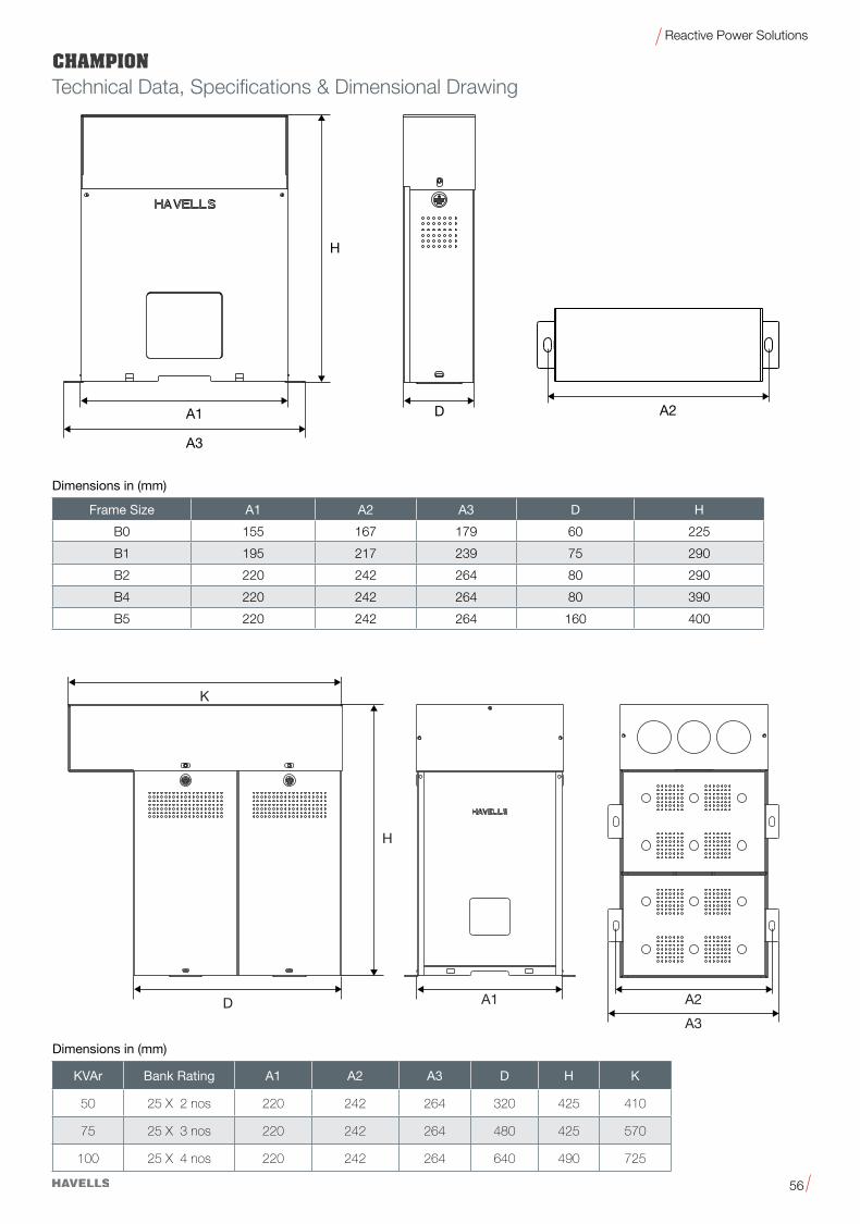
56
Reactive Power Solutions
Technical Data, Specifications & Dimensional Drawing
Dimensions in (mm)
Dimensions in (mm)
D A1 A2
A3
K
H
H
A1
A3
A2D
Frame Size A1 A2 A3 D H
B0 155 167 179 60 225
B1 195 217 239 75 290
B2 220 242 264 80 290
B4 220 242 264 80 390
B5 220 242 264 160 400
KVAr Bank Rating A1 A2 A3 D H K
50 25 X 2 nos 220 242 264 320 425 410
75 25 X 3 nos 220 242 264 480 425 570
100 25 X 4 nos 220 242 264 640 490 725

57
Reactive Power Solutions
*Packing units for capacitors equal minimum order quantity. Orders will be rounded up to packing unit or multiple thereof. Note:Customized products available upon request. Minimum Order Quantity 50 Nos. All Master Plus – Type capacitors may be used for 60Hz, the output will be 1.2 times higher
KVArCurrent
(A)KVAr
Current (A)
Capacitance (3XµF)
Frame SizePack Unit*
Product Code
50Hz 60Hz
Rated Voltage 415 V AC
1 1.4 1.2 1.7 6.2 B1 1 QHSTMB5001X0
2 2.8 2.4 3.3 12.3 B1 1 QHSTMB5002X0
3 4.2 3.6 5 18.5 B2 1 QHSTMB5003X0
4 5.6 4.8 6.7 24.6 B2 1 QHSTMB5004X0
5 7 6 8.3 30.8 B2 1 QHSTMB5005X0
6 8.3 7.2 10 37 B4 1 QHSTMB5006X0
7 9.7 8.4 11.7 43.1 B4 1 QHSTMB5007X0
7.5 10.4 9 12.5 46.2 B4 1 QHSTMB5007X5
8 11.1 9.6 13.4 49.3 B4 1 QHSTMB5008X0
10 13.9 12 16.7 61.6 B4 1 QHSTMB5010X0
12.5 17.4 15 20.9 77 B4 1 QHSTMB5012X5
15 20.9 18 25 (2 X46.2) B5 1 QHSTMB5015X0
20 27.8 24 33.4 (2 X 61.6) B5 1 QHSTMB5020X0
25 34.8 30 41.7 (2 X 77.0) B5 1 QHSTMB5025X0
30 41.7 36 50.1 (4 X 46.2) 15 X 2 NOS* 1 QHSTCB5030X0
50 69.6 60 83.5 (4 X 77.0) 25 X 2 NOS* 1 QHSTMB5050X0
75 104.3 90 125.2 (6 X 77.0) 25 X 3 NOS* 1 QHSTMB5075X0
100 139.1 120 166.9 (8 X 77.0) 25 X 4 NOS* 1 QHSTMB5100X0
Rated Voltage 440 V AC
1 1.3 1.2 1.6 5.5 B1 1 QHSTMC5001X0
2 2.6 2.4 3.1 11 B1 1 QHSTMC5002X0
3 3.9 3.6 4.7 16.4 B2 1 QHSTMC5003X0
4 5.2 4.8 6.3 21.9 B2 1 QHSTMC5004X0
5 6.6 6 7.9 27.4 B2 1 QHSTMC5005X0
6 7.9 7.2 9.4 32.9 B4 1 QHSTMC5006X0
7 9.2 8.4 11 38.4 B4 1 QHSTMC5007X0
7.5 9.8 9 11.8 41.1 B4 1 QHSTMC5007X5
8 10.5 9.6 12.6 43.8 B4 1 QHSTMC5008X0
10 13.1 12 15.7 54.8 B4 1 QHSTMC5010X0
12.5 16.4 15 19.7 68.5 B4 1 QHSTMC5012X5
15 19.7 18 23.6 (2 X 41.1) B5 1 QHSTMC5015X0
20 26.2 24 31.5 (2 X 54.8) B5 1 QHSTMC5020X0
25 32.8 30 39.4 (2 X 68.5) B5 1 QHSTMC5025X0
30 39.4 36 47.2 (4 X 41.1) 15 X 2 NOS* 1 QHSTMC5030X0
50 65.6 60 78.7 (4 X 68.5) 25 X 2 NOS* 1 QHSTMC5050X0
75 98.4 90 118.1 (6 X 68.5) 25 X 3 NOS* 1 QHSTMC5075X0
100 131.2 120 157.5 (8 X 68.5) 25 X 4 NOS* 1 QHSTMC5100X0
Three phase power capacitor (super heavy duty)

58
Reactive Power Solutions
Anti-Resonance Harmonic Filter
GeneralThe increasing use of modern power electronic apparatus (drives, uninterruptible power supplies, etc) produces nonlinear current and thus influences and loads the network with harmonics (line pollution). The power factor correction or capacitance of the power capacitor forms a resonant circuit in conjunction with the feeding transformer. Experience shows that the selfresonant frequency of this circuit is typically between 250 and 500 Hz, i.e. in the region of the 5th and 7th harmonics.
Sucharesonancealthoughcanleadtothefollowingundesirableeffects:
• Overloadingofcapacitors
• Overloadingoftransformersandtransmissionequipment
• Interferencewithmeteringandcontrolsystems,computersandelectricalgear
• Resonanceelevation,i.e.amplificationofharmonics
• Voltagedistortion.
These resonance phenomena can be avoided by connecting capacitors in series with filter reactors in the PFC system. These so called “detuned” PFC systems are scaled. in a way that the self-resonant frequency is below the lowest line harmonic. The detuned PFC system is purely inductive seen by harmonics above this frequency. For the base line frequency (50 or 60 Hz usually), the detuned system on the other hand acts purely capacitive, thus correcting the reactive power.
Applications•Avoidanceofresonanceconditions
•Tunedanddetunedharmonicfilters
•Reductionofharmonicdistortion(networkclearing)
•Reductionofpowerlosses
Features•Highharmonicloadingcapability
•Verylowlosses
•Highlinearitytoavoidchoketilt
•Lownoise
•Convenientmounting
•Longexpectedlifetime
•Temperatureprotection(NCcontact)
Mechanical and maintenance•Lowmountingcosts
•Easyinstallationandconnection
•Compactvolume
•Maintenance-free
Safety•Temperatureprotection

59
Reactive Power Solutions
Technical Data
Reference Standard IEC 61558 / IS 5553
Tolerance of Inductance ±3%
Harmonics*
V3=0.5%VR(dutycycle=100%)
V5=6.0%VR(dutycycle=100%)
V7=5.0%VR(dutycycle=100%)
V11=3.5%VR(dutycycle=100%)
V13=3.0%VR(dutycycle=100%)
Effective current Irms Irms = ß®(I12+I32 ... I132)
Fundamental current I I1 = 1.06 · IR (50 Hz or 60 Hz current of capacitor)
Insulation (winding-core) Kv 3 Kv
Temperature protection Microswitch (NC)
Dimensional drawings and terminals
See specific datasheets
Three-phase filter reactors to EN 60289 / IEC 61558
Frequency f 50 Hz or 60 Hz
Voltage V AC 400, 440 V AC
Output KVAr 5 … 100 KVAr
Detuning Factor 5.67%,7%,14%
Cooling Natural
Ambient temperature °C 40°C
Humidity 95%
Insulation class H
Class of protection I
Enclosure IP00
Max. Permissible Attitude Max. 4000M above sea level
Terminals Lugs / Busbar
Design Data
Dimensions According to specification table page no
Weight Approx. According to specification table page no
Safety- All reactors are provided with a sepaerate screw terminal for the temperature switch (opening switch) which is located indisde the central coil.
Response Temperature °C 1400C
Voltage V AC 250 V AC (<4A) ... 500 V AC (<2A)
Ordering Code QHDTM*
Anti-Resonance Harmonic Filter

60
Reactive Power Solutions
Selection of Filter
Determine the necessary effective power (KVAr) of the capacitor
bank in order to obtain the desired PF.
Design the capacitor stages in such a way that the sensitivity of
thebank isaround15–20%ofthetotalavailablepower. It’snot
usefultohaveamoresensitivebankthatreactswitha5or10%
of the total power because this would lead to a high amount of
switching operations, wasting the equipment unnecessarily when
the real objective is to have a high average PF.
Try to design the bank with standard KVAr values of effective
power steps, preferably multiples of 25 KVAr
Measure the presence of harmonic currents in the main feeder
cable of the system without capacitors at all possible load
conditions. Determine frequency and maximum amplitude for
every harmonic that could exist. Calculate the Total Harmonic
Distortion of Current
THD-I=100•SQR[(I3)2+(I5)2+...+(IR)2]/Il
CalculateeveryexistingvalueforTHD-IR=100•IR/Il
Measure the presence of harmonic voltages that might come from
outside your system, if possible measure the HV side.
Calculate the Total Harmonic Distortion of Voltage
THD-V=100•SQR[(U3)2+(U5)2+...+(UN)2]/Ul
The following table shows a comparison for various reactor/
capacitorcombinationsatfundamentalfrequencyof50Hz:
p -Detuned factor
f - Fundamental frequency
f Res -Resonating frequency
Resonance frequency De-tuning factor
210 Hz 5.67189 Hz 7134 Hz 14
Losses
The 50 Hz losses are comparatively low but when the filter circuit reactors are installed into the cabinet, they are charged with additional currents, predominantly those of the 5, 7 & 11 harmonics. Then the total heat losses dissipated can be of a level whereby they have to be extracted from the cabinet, by means of fans.
Terminals:theterminalsforfiltercircuitreactorsaredesignedascable terminals.
Design Features
Havells filter reactors are designed with properties like low temperature rise and lower flux density so that it can operate with worst conditions of Harmonic overloads. Reactors are available withdetunedfactorof5.67%,7%and14%in5,10,15,20,25,50 KVAr rating. Any other specific rating can be made as per the request from the customer.
An integrated switch allows external monitoring and/ or discon-nection of the reactor in the event of impermissible built up of heat.
Anti-Resonance Harmonic Filter

61
Reactive Power Solutions
When installing capacitors for PFC purpose, the problem ofdealing with harmonics has to be faced. They have to be taken into account when designing the PFC system in order to prevent parallel and / or series resonance conditions that would damage thewholeelectricalsystem.WhenPFCcapacitorsareconnected,the inductance of the transformer together with the capacitors forms a resonant circuit that could be excited by a harmonic current generated by the load. This resonant circuit has a resonance frequency, and if a harmonic current of this frequency (or close to it) exists, it will lead the circuit into a resonance condition where high currentwill flow through the branches (L: the transformer,and C: the capacitor bank), overloading them and raising thevoltage across them and across the whole electrical system that is connected in parallel. PFC detuned filtering is a tech nique to correct the power factor avoiding the risk of resonance condition performed by shifting the resonance frequency to lower values where no harmonic currents are present.
This is achieved by modifying the basic LC circuit formed by the transformer and the capacitor bank, introducing a filter reactor in series with the capacitors, making this way a more complex resonant circuit but with the desired feature of having a resonance frequency below the first existing harmonic. This way it’snotpossibletohavearealresonancecondition.Besidesthismain objective, the reactor connected in series with capacitors form a series resonant circuit with a certain tuning frequency at which the branch will offer a low impedancepath. Filtering of harmonic currents and “cleaning” of the grid will be achieved. Components for PFC detuned filters must be carefully selected according to the desired PFC purpose, to the harmonics present in the system, to some features of the system like short circuit power and impedances, to the desired filtering effect and to the characteristics of the resonant circuit configured.
For example, the voltage across the capacitors will be higher than the nominal grid voltage when they have a reactor connected in series. The reactors must be selected in line with the inductance value to obtain the desired tuning frequency and current capabi lity high enough for the harmonic current absorption that can be expected. The tuning frequency is usually indirectly referred to as the detuning factor p and expressed as a percentage.
Detuned PFC in general
XL ƒ 2p = 100 · ––– = (–––––) · 100
XC ƒRES
Detuned PFC Important Facts and InstructionsImportant design instructions to be followed for detuned PFC Systems
1) Determine the necessary effective power (KVAr) of the capacitor bank in order to obtain the desired PF.
2) Design the capacitor stages in such a way that the sensibility of the bank is around 15–20% of the total available power.It’snotusefultohaveamoresensitivebankthatreactswitha5or10%of the totalpowerbecausethiswould leadtoahigh amount of switching operations, wasting the equipment unnecessarily when the real objective is to have a high average PF.
3) Try to design the bank with standard KVAr values of effective power steps, preferably multiples of 25 KVAr.
4) Measure the presence of harmonic currents in the main feeder cable of the system without capacitors at all possible load conditions. Determine frequency and maximum ampli tude for every harmonic that could exist. Calcu late the Total Harmonic DistortionofCurrentTHD-I=100·SQR[(I3)2+(I5)2+...+(IR)2]/IlCalculateeveryexistingvalueforTHD-IR=100·IR/Il
5) Measure the presence of harmonic voltages that might come from outside your system, if possible measure the HV side. Calculate the Total Harmonic Distortion of Voltage THD-V = 100·SQR[(V3)2+(V5)2+...+(VN)2]/Vl
6) Are thereharmonicssuchasTHD-I>10%orTHD-V>3%(measured without capacitors)? If YES use PFC-DF and go to consideration 7. If NO use standard PFC and skip considerations 7, 8 and 9.
7) Is there 3rd harmonic content, I3 > 0.2 · I5? If YES use PFC-DFwithp=14%andskipconsideration8.IfNOusePFC-DFwithp=7%or5.67%andgotoconsideration
8) THD-Vis:3–7%usePFC-DFwithp=7%>7%usePFC-DFwithp=5.67%>10%askforspecialfilterdesign
9) Select the proper components using Havells tables for PFC-DF and standard values for effective power, the voltage and frequency of your grid, and the determined detuned factor p.
10) Always use genuine Havells application-specific designed components for PFC-DF. Please observe that reactors are specified for their effective power at grid voltage and frequency. This power will be the real effective power of the whole LC set at fundamental frequency. Capacitors for PFC-DF must beselectedforahigherratedvoltagethanthegrid’sbecauseof the overvoltage caused by the series connection with the reactor. Contactors for capacitors are designed as application-specific to reduce inrush capacitors currents and to handle capacitive loads in a reliable way.
PFC detuned filtering is an engi neer ing speciality that takes ex per ienced know-how to implement it in a satisfying and safe way. The design-instructions for detuned PFC systems on page 75 have to be followed to ensure an optimum performance of the PFC system.
Note: The recommendations given in the selection tables aremeant as a support tool. does not take over any responsibility for the design as apart from the theoretical conditions the prevailing circumstances in the application have to be taken into account.

62
Reactive Power Solutions
Technical Data and Specifications
Notes: 1) AllDimensionsareinM.M. 2) ToleranceonDimension-Overall(L,W,H)-+/-1% Mounting - +/-2MM" 3) Total max. losses, considering max. specified overvoltage and harmonic currents* 4) Other Voltages on request 5) Other Voltages/KVAr drawing may be changed QHDTMCV005X0:5KVAr/440V-OrderforothervoltagesReplace C with Q for 400V
QHDTMCV005X0:5KVAr/440V-OrderforotherdetuningfactorReplace V with U for 5.67% and W for 14%
U V W
50Hz
5.67% 7% 14%
Q C
400V 440V
Anti-Resonance Harmonic Filter
Ordering Code
Copper
QHDTMCV005X0
QHDTMCV010X0
QHDTMCV012X5
QHDTMCV015X0
QHDTMCV020X0
QHDTMCV025X0
QHDTMCV050X0
QHDTMCV075X0
QHDTMCV100X0
QHTTMCV010X0
QHTTMCV012X5
QHTTMCV015X0
QHTTMCV020X0
QHTTMCV025X0
QHTTMCV050X0
QHTTMCV075X0
QHTTMCV100X0
QHTTMCV005X0
Aluminium
KVAr Current InductanceNet
WeightLosses
Insulation Class
A mH Kg Watts L W H n1 n2 b Ød1 Slotsize
dist between
slot ØG
5 6.56A 9.33mH 9 70W H 220 145 165 140 90 125 8 7 x 20 60 6
10 13.12A 4.64mH 11 80W H 220 145 165 140 90 125 8 8 x 25 60 6
12.5 16.6A 3.71mH 15 90W H 220 145 165 140 90 125 8 8 x 25 60 6
15 19.68A 3.10mH 20 130W H 225 145 205 150 94 116 8 7 x 20 76 6
20 26.24A 2.31mH 20 150w H 225 145 205 150 94 116 8 7 x 20 76 8
25 32.8A 1.86mH 24 170w H 225 145 205 150 94 116 8 7 x 20 76 8
50 65.6A 0.926mH 35 250w H 265 170 235 150 104 132 8 7 x 20 88 8
75 99A 0.618mH 47 340w H 300 175 270 265 113 143 10 10 x 20 100 10
100 131.5A 0.464mH 58 380w H 300 200 270 265 140 170 10 10 x 20 100 10
5 - - - - - - - - - - - - - - -
10 13.12A 4.64mH 10 90w H 220 150 165 150 90 125 8 8 x 25 65 6
12.5 16.6A 3.71mH 12 100w H 240 160 165 150 90 125 8 8 x 25 65 8
15 19.68A 3.10mH 20 140w H 225 175 205 150 94 116 8 7 x 20 76 8
20 26.24A 2.10mH 20 160w H 225 175 210 150 94 116 8.5 7 x 20 76 8
25 32.5A 37.2mH 20 180w H 240 190 210 170 94 116 8.5 7 x 20 86 8
50 65.6A 0.926mH 28 270w H 285 220 235 210 104 132 8.5 7 x 20 103 10
75 99A 0.618mH 41 360w H 340 180 270 265 113 143 10 10 x 20 115 10
100 131.5A 0.464mH 52 400w H 340 270 270 265 140 170 10 10 X 20 115 12
Dimensions (mm)/Tolerance
Elevation
Busbar
d60
n1 n2
b
H
W
L
R.H. Side View
G

63
Reactive Power Solutions
Anti-Resonance Harmonic Filter
Calculation of the requested rated capacitor output in detuned filter circuits (factors to be multiplied with the required output per step
Example:Requiredoutputperstepatsupplyvoltage: 50KVAr
Supplyvoltage: 440V
Detuningfactor: 7%
Ratedvoltageofcapacitor: 525V
Factorofthetable: 1.324
Requestedratedoutputofthecapacitors:50KVArX1.327= 66.2
Selection:2(PFCcapacitors)x 33.1
* For filter circuits the capacitor rated voltage has to be chosen always higher than the supply voltage. i.e.:fundamentalvoltageincreasedbythereactorandharmonics
Rated voltage *of capacitor (V)
Detuning Factor (%)
5 5.5 6 7 12.5 13 14
440 1.068 1.062 1.057 - - - -
525 1.520 1.512 1.504 1.488 1.400 1.392 1.376
Rated voltage *of capacitor (V)
Detuning Factor (%)
5 5.5 6 7 12.5 13 14
440 1.150 1.143 1.137 1.125 - - -
525 1.637 1.628 1.619 1.602 1.507 1.499 1.481
Supply Voltage: 400V
Supply Voltage: 415V
Supply Voltage: 440V
Supply Voltage: 480V
Rated voltage *of capacitor (V)
Detuning Factor (%)
5 5.5 6 7 12.5 13 14
525 1.352 1.345 1.338 1.324 1.246 1.239 1.224
Rated voltage *of capacitor (V)
Detuning Factor (%)
5 5.5 6 7 12.5 13 14
525 1.136 1.130 1.125 1.113 - - -
660 1.796 1.787 1.777 1.758 1.654 1.645 1.626

64
Reactive Power Solutions
Detuned factor %
Effective filter output KVAr
Grid voltage
Capacitor voltage Selection
Capacitor output KVAr
Capacitance 3 * µF
Reactor inductivity 3 * mH
IRMS(Ieff)
Rated voltage V = 400 V, f = 50 Hz, p = 5.67% (fr = 210 Hz) / Linearity: L ≥ 0.95 * LR for current up to 2.08 * I1
5.67
5.00 KVAr
400 V 440 V
5.71 KVAr 31.3 µF 6.13 mH 8.78 AMP
10.00 KVAr 11.41 KVAr 62.6 µF 3.06 mH 17.55 AMP
12.50 KVAr 14.27 KVAr 78.2 µF 2.45 mH 21.94 AMP
15.00 KVAr 17.12 KVAr 93.9 µF 2.04 mH 26.33 AMP
20.00 KVAr 22.83 KVAr 125.2 µF 1.53 mH 35.11 AMP
25.00 KVAr 28.53 KVAr 156.5 µF 1.23 mH 43.88 AMP
40.00 KVAr 45.66 KVAr 250.3 µF 0.77 mH 70.21 AMP
50.00 KVAr 57.07 KVAr 312.9 µF 0.61 mH 87.76 AMP
75.00 KVAr 85.60 KVAr 469.4 µF 0.41 mH 131.65 AMP
100.00 KVAr 114.14 KVAr 625.9 µF 0.31 mH 175.53 AMP
Rated voltage V = 400 V, f = 50 Hz, p = 7% (fr = 189 Hz) / Linearity: L ≥ 0.95 * LR for current up to 1.73 * I1
7
5.00 KVAr
400 V 440 V
5.63 KVAr 30.9 µF 7.67 mH 8.03 AMP
10.00 KVAr 11.25 KVAr 61.7 µF 3.84 mH 16.07 AMP
12.50 KVAr 14.07 KVAr 77.1 µF 3.07 mH 20.09 AMP
15.00 KVAr 16.88 KVAr 92.6 µF 2.56 mH 24.10 AMP
20.00 KVAr 22.51 KVAr 123.4 µF 1.92 mH 32.14 AMP
25.00 KVAr 28.13 KVAr 154.3 µF 1.53 mH 40.17 AMP
40.00 KVAr 45.01 KVAr 246.8 µF 0.96 mH 64.28 AMP
50.00 KVAr 56.27 KVAr 308.5 µF 0.77 mH 80.34 AMP
75.00 KVAr 84.40 KVAr 462.8 µF 0.51 mH 120.52 AMP
100.00 KVAr 112.53 KVAr 617.0 µF 0.38 mH 160.69 AMP
Rated voltage V = 400 V, f = 50 Hz, p = 14% (fr = 135 Hz) / Linearity: L ≥ 0.95 * LR for current up to 1.37 * I1
14
5.00 KVAr
400 V 480 V
6.19 KVAr 28.5 µF 16.59 mH 7.69 AMP
10.00 KVAr 12.38 KVAr 57.1 µF 8.30 mH 15.39 AMP
12.50 KVAr 15.48 KVAr 71.3 µF 6.64 mH 19.23 AMP
15.00 KVAr 18.58 KVAr 85.6 µF 5.53 mH 23.08 AMP
20.00 KVAr 24.77 KVAr 114.1 µF 4.15 mH 30.77 AMP
25.00 KVAr 30.96 KVAr 142.6 µF 3.32 mH 38.46 AMP
40.00 KVAr 49.54 KVAr 228.2 µF 2.07 mH 61.54 AMP
50.00 KVAr 61.92 KVAr 285.3 µF 1.66 mH 76.93 AMP
75.00 KVAr 92.88 KVAr 427.9 µF 1.11 mH 115.39 AMP
100.00 KVAr 123.84 KVAr 570.6 µF 0.83 mH 153.85 AMP
Component selection table for dynamic pfc Anti-resonance Filter Circuit
Grid: 400 V - 50 Hz Detuned Filters components selection table
Anti-Resonance Harmonic Filter

65
Reactive Power Solutions
Detuned factor %
Effective filter output KVAr
Grid voltage
Capacitor voltage Selection
Capacitor output KVAr
Capacitance 3 * µF
Reactor inductivity 3 * mH
IRMS(Ieff)
Rated voltage V = 440 V, f = 50 Hz, p = 5.67% (fr = 210 Hz) / Linearity: L ≥0.95•LRforcurrentupto2.08•I1
5.67
5.00 KVAr
440 V 480 V
5.61 KVAr 25.9 µF 7.41 mH 7.98 AMP
10.00 KVAr 11.23 KVAr 51.7 µF 3.71 mH 15.96 AMP
12.50 KVAr 14.03 KVAr 64.7 µF 2.96 mH 19.95 AMP
15.00 KVAr 16.84 KVAr 77.6 µF 2.47 mH 23.94 AMP
20.00 KVAr 22.45 KVAr 103.4 µF 1.85 mH 31.91 AMP
25.00 KVAr 28.07 KVAr 129.3 µF 1.48 mH 39.89 AMP
40.00 KVAr 44.90 KVAr 206.9 µF 0.93 mH 63.83 AMP
50.00 KVAr 56.13 KVAr 258.6 µF 0.74 mH 79.78 AMP
75.00 KVAr 84.20 KVAr 387.9 µF 0.49 mH 119.68 AMP
100.00 KVAr 112.26 KVAr 517.2 µF 0.37 mH 159.57 AMP
Rated voltage V = 440 V, f = 50 Hz, p = 7% (fr = 189 Hz) / Linearity: L ≥0.95•LRforcurrentupto1.73•I1
7
5.00 KVAr
440 V 480 V
5.53 KVAr 25.5 µF 9.33 mH 7.30 AMP
10.00 KVAr 11.07 KVAr 51.0 µF 4.64 mH 14.61 AMP
12.50 KVAr 13.83 KVAr 63.7 µF 3.71 mH 18.26 AMP
15.00 KVAr 16.60 KVAr 76.5 µF 3.10 mH 21.91 AMP
20.00 KVAr 22.14 KVAr 102.0 µF 2.31 mH 29.22 AMP
25.00 KVAr 27.67 KVAr 127.5 µF 1.86 mH 36.52 AMP
40.00 KVAr 44.27 KVAr 204.0 µF 1.16 mH 58.43 AMP
50.00 KVAr 55.34 KVAr 255.0 µF 0.93 mH 73.04 AMP
75.00 KVAr 83.01 KVAr 382.5 µF 0.62 mH 109.56 AMP
100.00 KVAr 110.68 KVAr 509.9 µF 0.46 mH 146.08 AMP
Rated voltage V = 440 V, f = 50 Hz, p = 14% (fr = 135 Hz) / Linearity: L ≥0.95•LRforcurrentupto1.37•I1
14
5.00 KVAr
440 V 525 V
6.12 KVAr 23.6 µF 20.07 mH 6.99 AMP
10.00 KVAr 12.24 KVAr 47.2 µF 10.04 mH 13.99 AMP
12.50 KVAr 15.30 KVAr 58.9 µF 8.03 mH 17.48 AMP
15.00 KVAr 18.37 KVAr 70.7 µF 6.69 mH 20.98 AMP
20.00 KVAr 24.49 KVAr 94.3 µF 5.02 mH 27.97 AMP
25.00 KVAr 30.61 KVAr 117.9 µF 4.01 mH 34.97 AMP
40.00 KVAr 48.97 KVAr 188.6 µF 2.51 mH 55.95 AMP
50.00 KVAr 61.22 KVAr 235.8 µF 2.01 mH 69.93 AMP
75.00 KVAr 91.83 KVAr 353.7 µF 1.34 mH 104.90 AMP
100.00 KVAr 122.44 KVAr 471.6 µF 1.00 mH 139.87 AMP
Grid: 440 V - 50 Hz Detuned Filters components selection table
Anti-Resonance Harmonic Filter

66
Reactive Power Solutions
GeneralIPFC Relay for Power Factor Correction in Low Voltage applications measures the actual power factor and connect or disconnect capacitors to achieve a target power factor. The single phase electronic measuring system detects the reactive and active component of the network through the current and voltage path. From this it calculates the phase shift between current and voltage and compares this with the set target power factor.
If there are deviations of the power factor, capacitor stages are switched in and out by the IPFC relay. The contactor control logic is optimised so that the desired power factor is achieved with minimum switching operations, thus ensuring an optimised life cycle of the capacitor bank.
Features• User friendly program for target power factor, on/off delay, CT ratio.• Seven segment LCD display with backlight for readability in poorly illuminated areas.• Displayparameters–KW,PF,KVAr,KVA,Volt,Amp,Frequency.• Key pad for user interface.• Compatible with RS 232 (Galvanically isolated).• Recall function of recorded values.• Available in 6, 8, 12, 14 stages.• User configurable parameters - Target PF Setting, Power Factor Tolerance, CT ratio, total capacitor banks, under current, Over /
Under frequency, Over / Under voltage threshold for alarm / tripping capacitor bank, time delay between steps (2 sec - 1800 sec.).• Download Parameters - Target PF, CT ratio, total capacitor banks, Capcaitor banks status, under current, Over / Under voltage
threshold for alarm / tripping capacitor bank, Over / Under frequency threshold for alarm / tripping capacitor bank, time delay between steps (2 sec upto 1800 sec.).
• Loadsurveyfor40daysforeach30minuteintervalconsistingof:Activeenergy&demand,reactiveenergy&demand,apparentenergy & demand, average power factor, voltage (average 30 minutes), date, time.
• P.C. based software for data storing and system monitoring.
Mechanical and maintenance•Lowmountingcosts•Easyinstallationandconnection•Compactvolume•Maintenance-free
Microprocessor Controlled Power Factor Controller

67
Reactive Power Solutions
Microprocessor Controlled Power Factor Controller
Technical Data & Limit Values
Reference Standard IEC 61010-1
Parameters Unit Intelligent Power Factor Controller
Dimension m.m. 144 x 144 x 85
Weight kg. 0.75
Ambient conditions
Operating temperature Range °C –10 °C ... + 60 °C
Storage temperature Range °C –20 °C ... + 65 °C
Mounting position Flush Mounting in Vertical Plane
Protection class IP 54 ( Front)
Operation
Rated Operational Voltage V. AC 230VAC+-20%
Rated Operational Current I 50 mA – 6A (--/5 A Current Transformer)
Network Type SinglePhase,2Wire
Mains frequency Hz 50 / 60
Power consumption
Current I <2VA
Voltage V <10 VA
Target Power Factor Cos Φ 0.8 < cos Φ <= 1 (Inductive)
Switching Outputs
Capacitor Steps 6,8 , 12 Steps (Max.) + 1 Alarm
Relay Output Contact Max250AC,1000W
Switching time range 2 Sec. – 30 Min.
Control modes Automatic Bank Selection in accordance to Reactive Power Compensation
Ordering code QHOSRA*

68
Reactive Power Solutions
Operating Voltage (Un):230VAC±20%;50/60Hz
Operating Current 50 mA – 6 A (--/5 A Current Transformer)
Network Type 1 Phase, 2 wire
Capacitor Steps 6, 8, 12 steps (max) + 1 ALARM
Power Consumption < 2 VA (Current Circuit), < 10 VA (Voltage Circuit)
Output Contact 3 A, 750 VA
Cos Ø setting 0.8< cos Ø £ 1(Inductive)
Ambient Operating temp. -10° C, +60° C
Degree of Protection IP 54 (Front Panel)
Connection/ Installation Terminal / Flush - Mounting with rear terminals
Dimensions & 144 x 144 x 85 mm
PackingWeight 770 gm (Approx.)
CT Ratio Configurable (max. 1000/5)
Automatic Mode Capacitors connect automatically to achieve target power factor of Load
Manual mode By key pad to connect / disconnect the capacitors
Setting mode For user configurable target Power factor, CT_Ratio, Over / under Voltage limit and Over / Under Frequency limit tripping time, total no of capacitor banks
Communication RS 232
CONTROL PANEL To increase the value
To decrease the value
Scroll To scroll the parameters
Automatic/manual or setting mode selection by Keys
PROTECTION
• Over / Under Voltage
• Over / Under Frequency
• Over / Under Compensation
• Under current
PROGRAMMABLE PARAMETERS
• Target Power Factor Setting
• Power Factor Tolerance
• CT Ratio
• Total Capacitor Bank
• Number of Active Outputs
• Over / Under Voltage Threshold For Alarm / Tripping Capacitor Bank
• Over / Under Frequency Threshold For Alarm / Tripping Capacitor Bank
• Time Delay Between Steps (2 Sec Upto 1800 Sec.)
DOWN LOAD PARAMETERS
• Target Power Factor
• Power Factor Tolerance
• CT Ratio
• Total Capacitor Bank
• Capacitor Bank Status
• Over / Under Voltage Threshold for Alarm / Tripping Capacitor Bank
• Over / Under Frequency, Under Current Threshold for Alarm / Tripping Capacitor Bank
• Time Delay Between Steps (2 Sec Upto 1800 Sec.)
• Load survey for 40 days for each 30 minute interval consistingof:
- Active Energy & demand
- Reactive Energy & demand
- Apparent Energy & demand
- Voltage (Average 30 minutes)
- Average Power Factor
- Date & Time
FAULT / ALARM INDICATION
• Alarm relay contact is closed when the fault occur in the AC main supply for persistance of 5 sec. or more
• Alarm display on the LCD will appear in the event of any abnormaility.Example:
- Over / Under Voltage
- Over / Under Frequency
- Over / Under Compensation
- Under Current
Microprocessor Controlled Power Factor Controller
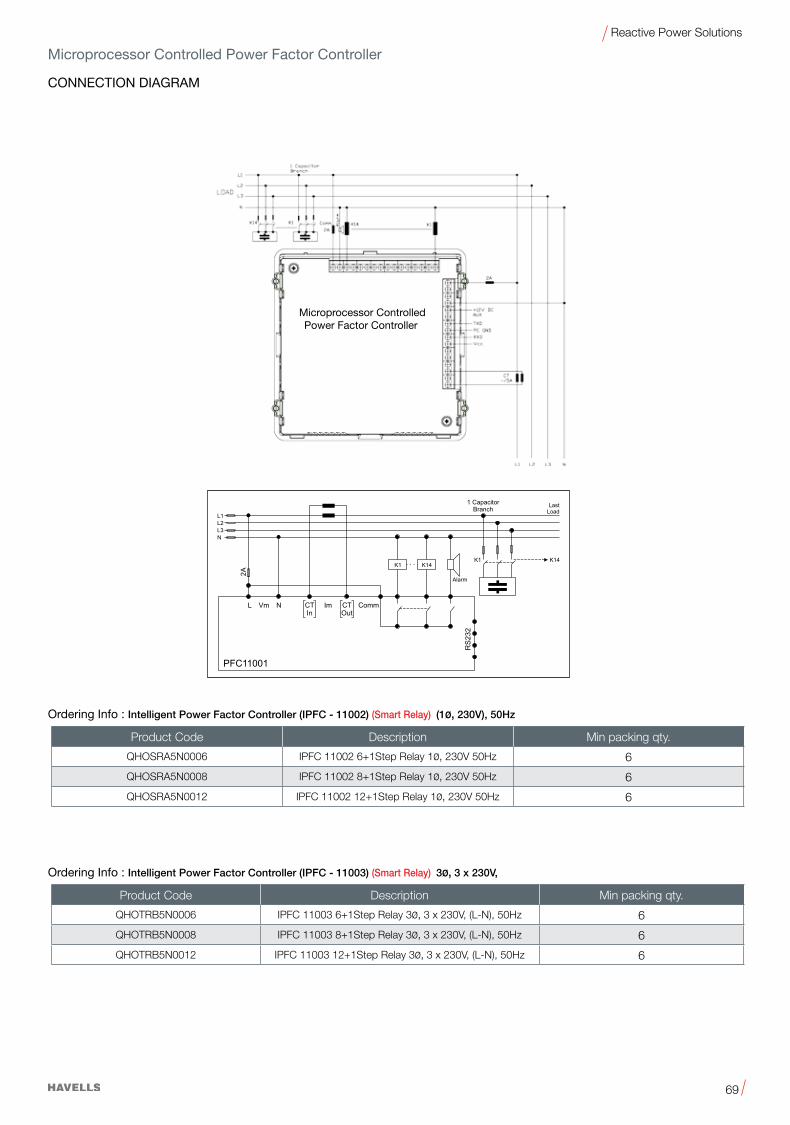
69
Reactive Power Solutions
CONNECTION DIAGRAM
Microprocessor Controlled Power Factor Controller
Microprocessor Controlled Power Factor Controller
Ordering Info : Intelligent Power Factor Controller (IPFC - 11002) (Smart Relay) (1ø, 230V), 50Hz
Ordering Info : Intelligent Power Factor Controller (IPFC - 11003) (Smart Relay) 3ø, 3 x 230V,
Product Code Description Min packing qty.
QHOSRA5N0006 IPFC 11002 6+1Step Relay 1ø, 230V 50Hz 6
QHOSRA5N0008 IPFC 11002 8+1Step Relay 1ø, 230V 50Hz 6
QHOSRA5N0012 IPFC 11002 12+1Step Relay 1ø, 230V 50Hz 6
Product Code Description Min packing qty.
QHOTRB5N0006 IPFC 11003 6+1Step Relay 3ø, 3 x 230V, (L-N), 50Hz 6
QHOTRB5N0008 IPFC 11003 8+1Step Relay 3ø, 3 x 230V, (L-N), 50Hz 6
QHOTRB5N0012 IPFC 11003 12+1Step Relay 3ø, 3 x 230V, (L-N), 50Hz 6

70
Reactive Power Solutions
INSTALLATION AND MAINTENANCE
Ambient temperature
Capacitors are divided into temperature classes, Each class in represented by a number followed by a letter e.g. -250/D. The number is the lowest ambient temperature at which a capacitor may operate. The upper limit temperature is indicated by the letter D, standing for 550C. A maximum case temperature of 600C. must not be exceeded. Temperature is one of the main.
Exceeding maximum allowed temperature may set the safety device out of operation.
Inrush current
Switching LV PFC capacitors, especially when they are in parallel with others that are already energized, can cause high inrush currents of up to 200 times rated current. This leads to additional stress on contactors as well as capacitors and reduces their useful life. In addition, high inrush currents have a negative effect on power quality, producing transients and voltage drops.
As per IEC 60831 standard, a maximum of 5000 switching operations per year is acceptable.
Harmonics
Harmonics are produced in the operation of electric loads with a nonlinear voltage/current characteristic e.g. rectifiers and inverters for drives, welding apparatus and uninterruptible power supplies). Harmonics are sinusoidal voltages and currents with higher frequencies of a multiple of the 50 or 60 Hz line frequency.
Note:Inapplicationssubjecttoharmonics,youshouldonlyusepower capacitors with reactors, so called detuned capacitor banks. Depending on the selected series resonant frequency, part of the harmonic current is absorbed by the power capacitor. The remainder of the harmonic current flows into the superordinate system. The use of power capacitors with reactors reduces harmonic distortion and lesser the disturbing effect on proper operation of other electric loads.
A major reason for installing detuned capacitor banks is to avoid resonance. Resonance can multiply existing harmonics and create power quality problems, as well as causing damage to distribution equipment.
Resonance cases must be avoided by appropriate application design in any case!
Max. total rms capacitor current (incl. fundamental harmonic current) specified in technical data of the specific series must not be exceeded
Safety
• Ensure good effective grounding for capacitor enclosures.
• Provide means of disconnecting and insulating a faulty component/bank.
• Handle capacitors carefully, because they may still be charged even after disconnection due to faulty discharging devices.
• Follow good engineering practice.
• Do not use HRC fuses to power a capacitor up and down (risk of arcing).
• Remember that the terminals of capacitors, connected bus bars and cables as well as other devices may also be energized.
Over current and short circuit protection
• Use HRC fuses or MCCBs for short circuit protection. Short circuit protection and connecting cables should be selected so that 1.5 times the rated capacitor current can be permanently handled.
• HRC fuses do not protect a capacitor against overload-they are only for short circuit protection.
• The HRC fuse rating should be 1.6 to 1.8 times rated capacitor current.
• Do not use HRC fuses to switch capacitors (risk of arcing).
• Use thermal magnetic overcurrent relays for overload protection.
Maintenance
• Periodically check that connections and terminals are tight.
• Regularly clean terminals/bushing to avoid short circuits due to dust and soiling.
• Check short circuit protection fuses.
• Make a current reading twice annually to see if application conditions have altered.
• Consider upgrading or modifying the PFC system if the application environment has changed.
• In the event of a current above nominal, check your application for possible modification.
• In the event of a significant increase in nonlinear loading, call consultant for a harmonics examination.
• If harmonics are present consider installation of a detuned capacitor bank (reactors).
• Checkdischargeresistors/reactorsandtheirfunctioning:
- Power the capacitor up and down
- The voltage across the terminals must fall to <50 V within 60s.
Capacitor life expectancy
Capacitors operation between any rated value and the corresponding absolute maximum rating is an overload that derates life expectancy of the device.
Simultaneous overload conditions or exceeding any absolute maximum rating may reduce life expectancy significantly.
Microprocessor Controlled Power Factor Controller

71
Reactive Power Solutions
PFC Basic Formulas
The following electrical formulas may be used to calculate basic PFC values.
Active power
The amount of input power converted to output power is the active power.
P = 3 · V · I · cos ϕ [W]
Reactive power
Q = 3 · V · I · sin ϕ [VAr]
Apparent Power
The apparent power is the power delivered to an electric circuit.
S = 3 · V · I [VA]
Power factor
Active power PPower factor = –––––––– = ––Apparent power S
Power Factor Correction
QC = P · (tan ϕ1 – tan ϕ2) [VAr]
QC: active power neededP: total reactive powerϕ1: actual angle of cos ϕ actualϕ2: target angle of cos ϕ target
The reactive power is the power consumed in an AC circuit due to the expansion and collapse of magnetic (inductive) and electrostatic (capacitive) fields.
The power factor of an AC electrical power system is defined as the ratio of the real (active) power to the apparent power.
When the AC load is partly capacitive or inductive, the current waveform is out of phase with the voltage. This requires additional AC current to be generated that is not consumed by the load, creating I2R losses in power cables. Capacitors are used to supply reactive energy to inductive loads. Reactive energy must be produced as closely as possible to the loads to prevent unnecessary flow of current in the network. This is known as power factor correction.
Connection and rating of capacitors
The reactive power of the capacitor is a function of its rated voltage andcurrent.
QC = VC · IC [VAr]
VC · VC (VC)2QC = –––––––– = –––––XC XC
f: frequency of networkXC: impedance of capacitorC: capacitance value
QC = (VC)2 · · C = (V C)2 · 2 · f · C
1 1XC = ––––– = –––––––––· C 2 · f · C

72
Reactive Power Solutions
PFC Basic FormulasCapacitor in three-phase PFC application
Three-phase PFC applications have two types of capacitor connections: star and delta.
DELTA connection - The capacitor is subject to line voltage of VL, phase to phaseThus total KVAR compansation is calculated as
VC = VL
QTOT = 3 · (VL)2 · · CDELTA
QTOT QTOTCDELTA = –––––––––– = ––––––––––––––3 · (VL)2 · 3 · (VL)2 · 2 · f
Delta connection
VL651 µF
STAR connection - The capacitor is subject to a voltage of ( )Thus total kVAR compansation is calculated as
QTOT = 3 · QC
VC = VL / 3
VL / 3
QTOT QTOTCSTAR = ––––––––– = –––––––––––––(VL)2 · (VL)2 · 2 · f
(VL)2QTOT = 3 · –––––– · · CSTAR( 3)2Star connection
VL
1954 µF
Capacitor output kvar:
From the formula if we find theQnew with ratio: C will be constant.
VNew 2 fNewQNew = (––––– ) · –––– · QCVR fR
Calculation example
Example 1:The relationship between active,reactive and real power and cos ϕ.
In the diagram below, the power triangle shows an initial power factorof 0.70 for a 100 kW (real power) inductive load. The reactive power re-quired by the load is 100 kvar. By in-stalling a 67-kvar capacitor, the apparent power is reduced from 142to 105 kvar, resulting in a 26% reduction in current. The power factoris improved to 0.95.
Power factor calculations:Before PFC: 100/142 = 0.70 or 70% After PFC: 100/105 = 0.95 or 95%
Real power = 100 kW
After PFC =105 kVA
Before PFC =142 kVA
Apparent power
Reactive powerBefore: 100 kvar
Reactive powerAfter: 33 kvar
Capacitance added = 67 kvar
These values are operating conditions:Qnew: new reactive powerVnew: new voltagefnew: new frequency
These values are the values capacitor is designed:QC: rated capacitor reactive powerVC: rated capacitor voltagefR: rated frequency
CSTARCDELTA = ––––––3
Conclusion:

73
Reactive Power Solutions
PFC Basic Formulas
Example 4:
Calculating apparent power - Due to power factor correction, the requried apparent power transmission can be reduce by
Reduction (S1-S2) in example 2
S1 – S2 = 70 kVA
Thus, additional power of 70 · (0.9) = 63 kW can be suppliedand transferred via the existing network.
Cable cross section calculation
Line current drawn by the motor:
I1 uncompensated load (0.7):
220 · 1 000I1 = ––––––––––––––––– = 412 A3 · 440 · (0.7)
I2 compensated load (0.9):
220 · 1 000I2 = ––––––––––––––––– = 320 A3 · 440 · (0.9)
Thus, the cable can carry an additional load of 92 A, or the designer can reduce the cable cross section.
S1 - Uncompensated loadS2 - Compensaited load
S2 = P / cos ϕ2 = 220 / 0.9= 244 kVA
S1 = P / cos ϕ1 = 220 / 0.7= 314 kVA
Example 3: Calculating capacitor ratings for
ni snoitcennoc RATS dna ATLEDexample 2
STAR connection: DELTA connection:
VC = VL = 440 V
QTOT QTOTCDELTA = –––––––––– = ––––––––––––––3 · (VL)2 · 3 · (VL)2 · 2 · f
118.8 · 1 000CDELTA = –––––––––––––––––––––3 · (440) 2 · 2 · 50
= 651 µF / Line (phase)
CTOT = 1 954 µF
VL 440VC = –––– = –––– = 254 V3 3
QTOT QTOTCSTAR = ––––––––– = –––––––––––––(VL)2 · (VL)2 · 2 · f
118.8 · 1 000CSTAR = –––––––––––––––––(440) 2 · 2 · 50
= 1 954 µF / Line (phase)
CTOT = 5 862 µF
Example 2: Calculation of capacitor rating forindustrial installation
Given parameters: Target to correct the power factor to 0.9:
Induction motor 220 kWNetwork 440 V AC, (line delta) 3-phaseFrequency 50 HzPower factor– Current cos ϕ 0.7– Target cos ϕ 0.9 118.8 kvar
440 V/ 50 Hz
M
220 kWcos ϕ = 0.7
cos ϕ1 = 0.7 tan ϕ1 = 1.02cos ϕ2 = 0.9 tan ϕ2 = 0.48
QC= P (tan ϕ1 – tan ϕ2) = 220 · 1000 (1.02 – 0.48) = 118.8 kvar

74
Reactive Power Solutions
Reactive power compensation for Motor
The recommended capacitor rating for motor should be Sized to compensateup to90%of themotormagnetizationCurrentofmotor, to avoid self excitation phenomenon. The below table gives the selection chart for Capacitors as per the hp rating of the motor.
Loads in industrial and public electrical networks are primarily of an ohmic inductive nature.
The purpose of systems for power factor correction in networks is to compensate the generated lagging reactive power by leading reactive power at defined nodes. In this way impermissibly high voltage drops and additional ohmic losses are also avoided. The necessary leading power is produced by capacitors parallel to the supply network, as close as possible to the inductive load. Static capacitive compensation devices reduce the lagging reactive power component transmitted over the network. If network conditions alter, the required leading reactive power can be matched in steps by adding and taking out single power capacitors (automatic PFC) to compensate the lagging reactive power.
Advantages of power factor correction
• Payback in 8 to 24 months through lower power costs.
Power factor correction reduces the reactive power in a system. Power consumption and thus power costs drops in proportion.
• Effective installation use
An improved power factor means that an electrical installation works more economically (higher effective power for the same apparent power).
• Improved voltage quality
• Reduced voltage drop
• Optimum cable design
Cable cross-section can be reduced with improvement of power factor (less current). In existing installations for instance, extra or higher power can be transmitted.
• Reduced transmission losses
The transmission and switching devices carry less current, i.e. only the effective power, meaning that the ohmic losses in the leads are reduced.
Main components of Capacitor
Power factor correction capacitors produce the necessary leading reactive power to compensate the lagging reactive power. PFC capacitors should be capable of withstanding high inrush currents caused by switching operations (>100*IR). If capacitors are connected in parallel, i.e. as banks, the inrush current will increase (=150*IR) because the charging current comes from the grid as well as from capacitors parallel to the one switched.
PFC controller
Modern PFC controllers are microprocessor based. The microprocessor analyses the signal from a current transformer and produces switching commands to control the contactors that add or remove capacitor stage Intelligent control by microprocessor-based PFC controllers ensures even utisation of capacitor stages, minimised number of switching operations and optimised life cycle of the capacitor bank.
Capacitor contactor
Contactors are electromechanical switching elements used to switch capacitors or reactors and capacitors in standard or detuned PFC systems. The switching operation can be performed by mechanical contacts or an electronic switch (semi conduction). Always used capacitor duty contactors for capacitor switching. The latter solution is preferable if fast switching is required for a
sensitive load for example.
Reactor
Power distribution networks are increasingly subjected to harmonic pollution from modern power electronic devices, so called nonlinear loads, e.g. drives, uninterruptible power supplies, electronic ballasts. Harmonics are dangerous for capacitors connected in the PFC circuit, especially if the capacitors operate at resonant frequency. The series connection of reactor and capacitor to detuned the series resonant frequency (the capacitor's resonant frequency) helps to prevent capacitor damage. Most critical frequencies are the 5th and 7th harmonic (250 and 350 Hz at 50 Hz). Detuned capacitor banks also help to reduce the harmonic distortion level and clean the network.
Fuse
A HRC fuse / MCCB acts as a safety device for short circuit protection.
• The HRC fuse rating should be 1.6 to 1.8 times nominal capacitor current.
*Above 250HP KVAr approximate 35% of the motor power
Motor HP
3000 rmp
1500 rmp
1000 rmp
750 rmp
600 rmp
500 rmp
5 2 2 2 3 3 3
7.5 2 2 3 3 3 3
10 3 3 4 5 5 5
15 3 4 5 7 7 7
20 5 6 7 8 8 10
25 6 7 8 9 9 12
30 7 8 9 10 10 15
40 9 10 12 15 16 20
50 10 12 15 18 20 22
60 12 14 15 20 25 25
75 15 16 20 22 25 30
100 20 22 25 26 32 35
125 25 26 30 32 35 40
150 30 32 35 40 45 50
200 40 45 45 50 55 60
250 45 50 55 60 65 70
Power capacitor rating for direct connection Induction Motors Capacitor KVAr at motor speed of

75
Reactive Power Solutions
Reactive power compensation for Transformer
Power and distribution transformers, which work on the principle
of electromagnetic induction, consume reactive power for their
own needs even when its secondary is not connected to any load.
The power factor will be very low under such situation. To improve
the power factor, it is required to connect a fixed capacitor or a
capacitor bank at the LT side of the transformer. Below table gives
the approximate KVAr of capacitors required.
KVA rating of the KVAr required for
Transformer compensation
Uptoandincluding315KVA 5%ofKVArating
315KVA-1000KVA 6%ofKVArating
Above1000KVA 8%ofKVArating
It is useful to note that, in the case of APFC system, the current
Transformer providing feedback to the APFC system must be
located in such a way that it does not measure this capacitor
current.
Welding Transformers
Single phase, Single Operator Three phase, Multi-operator
Welding Required Welding Required
Transformer Capacitor Type Transformer Capacitor
continous rating continuous rating
rating kVA KVAr rating kVA KVAr
9 4 300/3 54 16.5
12 6 300/6 90 30
18 8 300/9 122 45
24 12 300/12 453 60
30 15
36 18
Table of Capacitance value measured between Phase to Phase terminals
KVAr Output Capacitance
(µF) 400V
Output Capacitance
(µF) 415V
Output Capacitance
(µF) 440V
Output Capacitance
(µF) 480V
1 9.9 9.2 8.2 6.92 19.9 18.5 16.4 13.83 29.8 27.7 24.6 20.74 39.8 37.0 32.8 27.65 49.7 46.2 41.1 34.56 59.7 55.4 49.3 41.47 69.6 64.7 57.5 48.37.5 74.6 69.3 62.0 51.88 79.6 73.9 65.8 55.210 99.5 92.4 82.2 69.112.5 124.3 115.5 103.0 86.315 149.2 138.6 123.3 103.620 199.0 184.8 164.4 138.225 248.7 231.0 206.0 172.730 298.5 277.2 246.6 207.335 348.2 323.4 287.7 241.840 398.0 369.6 328.8 276.445 447.7 415.8 369.9 310.950 497.5 462.0 411.0 345.560 597.0 554.4 493.2 414.675 746.1 693.0 618.0 518.1100 995.0 924.0 822.0 691.0Note:Thetoleranceis-5%/+10%

76
Reactive Power Solutions
Standard Values: Selection Tables for Cables,Cable Cross Sections and FusesThe values mentioned in the following table are guidelines for operation in normal conditions at ambient temperatures up to 35°C. Upgrade accordingly if conditions differ, e.g. temperature or hamonics differ. The internal wiring of a capacitor bank is sometimes possible with a smaller cross section. Various parameters such as temperature inside the cabinet, cable quality, maximum cable insulation temperature, single or multi core cable, cable length and laying system have to be considered for a proper selection. The local panelbuilder/installer is responsible for a proper selection of the cable sizes and fuses according to the valid regulations and standards in the specific country where the PFC panels are installed.
Power Current Section FuseKVAr A mm2 A
Rated voltage 230 V, 60 Hz2.5 6.3 1.5 105 12.6 4 25
7.5 18.8 6 3510 25.1 10 50
12.5 31.4 16 5015 37.7 16 6320 50.2 25 8025 62.8 3 35 10030 75.3 50 12540 100.4 70 16050 125.5 95 20075 188.3 185 315
100 251 2 x 120.0 400125 – – –150 – – –175 – – –200 – – –
Rated voltage 400 V, 50 Hz2.5 3.6 1.5 105 7.2 2.5 16
7.5 10.8 2.5 1610 14.4 4 25
12.5 18 6 3515 21.6 6 3520 28.8 10 5025 36 16 6330 43.2 25 8040 57.6 35 10050 72 50 12575 108.3 70 160
100 144.3 120 250125 180.3 185 315150 216.5 2 x 95.0 350175 252.6 2 x 95.0 400200 288 2 x 120.0 500
Rated voltage 440 V, 60 Hz2.5 3.3 1.5 105 6.6 2.5 16
7.5 10 2.5 1610 13.2 4.0 25
12.5 16.8 4.0 2515 19.8 6.0 3520 26.4 10.0 5025 33 16.0 6330 39.6 25.0 8040 52.8 35.0 10050 66 50.0 12575 99 70.0 160
100 132 95.0 200125 165 185.0 315150 198 2 x 95.0 350175 231 2 x 95.0 400200 264 2 x 120.0 500
Selection Table

77
Reactive Power Solutions
Standard Values: Selection Tables for Cables, Cable Cross Sections and Fuses
Power Current Section FuseKVAr A mm2 A
Rated voltage 480 V, 60 Hz2.5 3 1.5 105 6 2.5 16
7.5 9 2.5 1610 12 4 25
12.5 18 6 3515 21 6 3520 24 10 5025 30 10 5030 36 16 6340 48 25 8050 60 35 10075 90 70 160
100 120 95 200125 150 120 250150 180 185 315175 210 2 x 95.0 350200 240 2 x 95.0 400
Rated voltage 525 V, 50 Hz2.5 2.7 1.5 105 5.5 1.5 10
7.5 6.9 2.5 1610 11 2.5 16
12.5 13.7 4 2515 16.5 4 2520 22 6 3525 27.5 10 5030 33 16 6340 44 25 8050 55 35 10075 82.5 70 160
100 110 95 200125 137.5 95 200150 165 185 300175 193 2 x 95.0 350200 220 2 x 95.0 350

78
Reactive Power Solutions
Temperature Class of Capacitors (according IEC 60831)
Enclosure of Capacitors (IPXX)
Maximum Admissible Overvoltage
Enclosure First digit Second digit
IP00 No protection against finger No protection touch and ingress of solid against ingress foreign bodies of water
IP20 Protection against finger touch No protection and solid foreign bodies against ingress 12.5 mm diameter of water
IP41 Protection against tool touch Drip-water and solid foreign protection bodies >1mm diameter
IP54 Protection against tool touch Splash water and solid foreign bodies >1mm protection diameter. Protection against dust deposit
Frequency Max. Max. Max. (50/60Hz) voltage duration duration (Vrms)
Line Frequency 1.00 VR Continuous Highest mean during duty entire operating time of capacitor, exceptions (see below) are admissible for times of <24h
Line Frequency 1.10 VR 8 h daily Line voltage fluctuations
Line Frequency 1.15 VR 30 min daily Line voltage fluctuations
Line Frequency 1.20 VR 5 min daily Line voltage fluctuations
Line Frequency 1.30 VR 1 min daily Line voltage fluctuations
Temperature Temperature of Maximum Maximum class capacitor surrounding mean mean air Maximum for 24 h for 1 year
B 45°C 35°C 25°C
C 50°C 40°C 30°C
D 55°C 45°C 35°C
Current rating/maximum admissible over current
The rated current (IR) is the current utilised for rated voltage (VR)
and frequency (in Hz.) excluding transient. Maximum permitted
rms current for each particular capacitor is specified in the data
sheet. Continuously exceeding of the nominal current will lead to
increased self heating of the capacitor and reduce life time. The
maximum admissible overcurrent (I max) of 1.3*IR to IEC 60831
standard is maintained by all capacitors is this catalogue. The
figures for overcurrent allow for the combined effects of harmonics,
overvoltage and capacitance tolerance.
CautionsTemperature class of capacitors to standard IEC 60831 / IS 13340
Capacitors are divided into temperature classes. Each class is
represented by a number followed by a letter. e.g. -25/D. The
number is the lowest ambient temperature at which a capacitor
may operate. the upper limit temperature is indicated by the letter
(see table above).
The use of a capacitor depends very much on temperature. Proper
cooling of a capacitor must ensure that the minimum temperature
is not exceeded of rewised useful life otherwise useful life is
degraded.Whenconfiguringacircuit,oneshouldmakesurethat
capacitors are not subjected to heat from adjacent components
(reactors, bus bars, etc.). Forced cooling is preferable for compact
designs and it is highly inadvisable to arrange capacitors directly
above reactors.

79
Reactive Power Solutions
Motor rating Capacitor rating Capacitor rating Capacitor rating (1500 rpm) (1000 rpm) (750 rpm)
kW1 … 9.1
2 … 9.2
3 … 9.3
4 … 9.4
5 … 9.5
6 … 9.7
8 … 9.01
11 … 9.31
14 … 9.71
18 … 9.12
22 …
kvar6.0
2.1
7.1
3.2
9.2
5.3
6.4
8.5
9.6
6.8
5.11
kvar5.0
1.1
6.1
1.2
6.2
2.3
2.4
3.5
3.6
0.8
5.01
kvar5.0
1
5.1
2
5.2
3
4
5
6
5.7
019.92
30 … e9.93
40 and aboverwop rotom eht fo %04 .xorppa
approx. 35% of the motor power
Individual PFC for MotorsApproximate values for fixed PFC of Motors
The capacitor output should be approx. 90% of the apparent power of the motor when idle.
This means a power factor of 0.9% at full load and 0.95 … 0.98 during idling. Important: The capacitor output must not be rated too high for individual compensated machines where the capacitor is directly connected with the motor clamp. This especially applies when the machine has a big oscillating weight and still continues to rotate after switching off. The capacitor placed in parallel may act as generator for the motor which will cause serious overvoltages. The consequence could be heavy damage to the capacitor as well as to the motor.
Individual PFC for Transformers
ANQC = I0% · ––––100
Qc = needed capacitor (kvar)I0% = magnetising current of the transformer (A S%)
AN = apparent rated power of the transformer in kVA
Standard values for transformer power factor correction
Rated apparent power Rated capacitor power Rated capacitor power of transformer for oil immersed transformers for cast resin transformers
kVA kvar kvar10
20
50
75
100
160
200
250
315
400
500
630
800
1000
1250
1600
2000
2500
3150
1.0
2.0
4.0
5.0
5.0
7.0
7.5
8.0
10.0
12.5
15.0
17.5
20.0
25.0
30.0
35.0
40.0
50.0
60.0
1.5
1.7
2.0
2.5
2.5
4.0
5.0
7.5
8.0
8.5
10.0
12.5
15.0
16.7
20.0
22.0
25.0
35.0
50.0
For an exact calculation of the right capacitor value, following formula can be used:
There are regional differences in the guidelines of power suppliers concerning the admissible size of capacitors directly connected with a transformer. Therefore a consultation with the respective power supplier is recommended before installation of a compensation bank. Modern transformers have laminations which only need low capacity to reverse the magnetism. In case the capacitor output is too high, stress increase may occur during idling.

80
Reactive Power Solutions
Self healing shield
Bellow shield
Notch shield } S3TripleSafety
Normal capacitor module
Fault operated capacitor module
Overpressure disconnector
Attheendofthecapacitor’sservicelifeorwhenahighpressure
forms inside the can, the overpressure disconnector is activated.
The specially designed cover with an expansion bead moves
upwards. Expansion beyond a certain degree will separate the
wires and disconnect the capacitor safely from the line. The
disconnector is separated at its break point (small notch) and the
flow of current to the capacitor windings is interrupted.
Caution:
To ensure full functionality of an overpressure disconnector, the
followingisrequired:
Cautions
1. The elastic elements must not be hindered, i.e.
– connecting lines must be flexible leads (cables),
– there must be sufficient space (at least 20 mm) for expansion
above the connections (specified for the different models),
– folding beads must not be retained by clamps.
2. The maximum permissible fault current of 10 000 A to the UL
810 standard must not be exceeded.
3. Stress parameters of the capacitor must be within the IEC
60831 / IS 13340 specification.

81
Reactive Power Solutions
Thumb Rule: The number of steps depends on the number of
loads, i.e. the more small inductive loads, the higher the number
of steps should be. The switching time is also of major importance
here:themorefrequentlyacapacitorisswitched,themorestress
is placed on it and its contactors.
Multi measuring device An external meter combining several
features in a single device. Combined with the appropriate PF
controller, it allows the monitoring, display and storage of various
grid parameters. It provides additional protection for the capacitor
and the PFC system. As a standalone solution, it acts as a meter,
a signal trigger for thyristor modules or as a switch.
Capacitor contactor
Contactors are electromechanical switching elements used to
switch capacitors or reactors and capacitors in standard or
detuned PFC systems. The pre-switching auxiliary contacts of
capacitor contactors close before the main contact and avoid
peak current values by pre-loading the capacitor. Note: Even
when using capacitor contactors, it is important not to exceed the
annual switching capability of the particular capacitor series.
Reactors - (compensation and filtering)
Power distribution networks are increasingly subjected to
harmonic pollution from modern power electronics devices,
known as non -linear loads, e.g. drives, uninter ruptible power
supplies and electronic ballasts. Harmonics are dangerous for
capacitors connected in the PFC circuit, especially if they operate
at a resonant frequency. The series connection of a reactor and
capacitortodetunetheseriesresonantfrequency(thecapacitor’s
resonant frequency) helps to prevent capacitor damage. The most
critical frequencies are the 5th and 7th harmonics (250 and 350
Hz at 50 Hz grid frequency). Detuned capacitor banks also help to
reduce the harmonic distortion level and clean the network.
Discharge devices
Discharge resistors are required to discharge capacitors and
protect human beings against electric shock hazards as well as to
switch capacitors in automatic PFC equipment (opposing phase).
Discharge resistors are designed to discharge capacitors to 50V
or less within 60 seconds.
Caution:
Discharge and short-circuit the capacitor before handling it!
Discharge reactor
Whenever fastdischargeof acapacitor is required, adischarge
resistor is not sufficient. Discharge reactors must be used to allow
a discharge of within a few seconds. Also, the various steps in a
PFC system can then be switched much faster, minimizing losses
at the same time.
Protection
An HRC fuse or MCCB acts as a safety device for short-circuit
protection. HRC fuses do not protect a ca pac - itor against
overload – they are designed for short-circuit protection only. The
HRC fuse rating should be 1.6 to 1.8 times the nominal capacitor
current.
Caution:
Do not use HRC fuses for switching (risk of arcing!).
Dry technology/ V ACuum impregnation
The active winding elements are heated and then dried for a
defined period. Impregnation is performed under V ACuum. In
this way, air and moisture are extracted from the inner capacitor,
and oxidation of the electrodes as well as partial discharges are
avoided. Afterwards, the capacitor elements are hermetically
sealed in cases (e.g. aluminum). This elaborate process ensures
excellent capacitance stability and long useful life.
Power factor controller Modern PF controllers are microprocessor-
based. The microprocessor analyzes the signal from a current
transformer and produces switching commands to control the
contactors that add or remove capacitor stages. Intelligent control
by microprocessorbased PF controllers ensures even utilization
of capacitor stages, a minimized number of switching operations
and an optimized life cycle of the capacitor bank. After the required
capacitor output has been determined, the number of steps

82
Reactive Power Solutions
Mean life expectancyThe mean life expectancy of power capacitors is mainly governed bythefollowingfactors:
- duration of overload.
- ambient temperature and the resulting case temperature.
- Maximum rms current and the resulting case temperature
The calculated life expectancy of the various series is stated for nominal operating conditions. If components are stressed less than the IEC 60831 factors, longer useful life can be expected, and a correspondingly shorter one or increased failure rate if nominal parameters are exceeded.
Fuse protectionPower capacitors have to be protected against short circuits by fuses or thermal magnetic overcurrent relays. Slow-blow, low-voltage high rupturing capacity fuses (HRC) are preferable. The fuse rating should be 1.6 to 1.8 times the rated current of the capacitor. Magnetic short circuit relays should be set to between 9 and 12 times rated current to prevent them responding to high inrush currents.
HRC fuses must not be used for switching as it results in electric arcing which can cause death ! It may also cause capacitor failures.
Switching of capacitorsWhenacapacitor isswitched toanACsystem, the result isaresonant circuit damped to a greater or lesser degree. In addition to the rated current, the capacitor accepts a transient current that is a multiple of (up to 200 times), its rated current. Fast switching, low-bounce contactors should be used, and have the switching capacity for capacitive currents stated by the producer. Special capacitor contactor with leading contacts that feature precharging resistors to damp inrush currents are recommended. As per IEC 60831 standard, a maximum of 5,000 switching operations per year is acceptable.
DischargingCapacitorsmustbedischargedtoamaximumof10%ofratedvoltage before they are switched in again. This prevents an electric impulse discharge in the application, influences the capacitor's useful life in PFC systems, and protects against electric shock. The capacitor must be discharged to 50 V or less within 60 sec. There must not be any switch, fuse or any other disconnecting device in the circuit between the power capacitor and the discharging device.
Caution:DISCHARGE CAPACITOR BEFORE HANDLING!
Capacitors in networks with harmonicsHarmonics are produced in the operation of electric loads with a nonlinear voltage/current characteristic (e.g. rectifiers and inverters for drives, welding apparatus and uninterruptible power supplies). Harmonics are sinusoidal voltages and currents with higher frequencies of a multiple of the 50 or 60 Hz line frequency.
In low-voltage three-phase systems the 5th and 7th harmonics are especially troublesome. Detuned filter (capacitor and reactor) should be used for power factor correction in systems subject to harmonics. These represent a series resonant circuit
Cautions of power capacitor and reactor. the circuit is tuned so that the series resonant frequency is below the lowest harmonics appearing in the system. This produces an inductive response to all frequencies above the series resonant frequency, avoiding resonances with system inductances. Depending on the selected series resonant frequency, part of the harmonic current is taken up by the detuned power capacitors. The remainder of the harmonic current flows into the superordinate system. The use of detuned power capacitors thus contributes to reducing voltage distortion through harmonics and lessens the disturbing effect on proper operation of other electric loads.
Most international standards limit THD-V on LV side to 5%However it has to be noted that in many grids these levels are exceeded and even lower distortion, e.g. 3-4% THD-V cangenerate extreme overcurrents in case of resonance condition.
Maximum overcurrents as specified under technical data of each series must not be exceeded.
Resonance must be avoided by appropriate pannel design. Resonance may cause very high overcurrents which can lead to capacitor failures and worst case, to explosion and fire.
ConnectionMake sure connection cables are of flexible type or flexible copper bands are used. This is mandatory to allow the overpressure disconnector work and avoid mechanical stress on the terminals and feedthroughs. The connection cables to the capacitor should be designed for a current of at least 1.5 times the rated current so that no heat is conducted into the capacitor. If reactors are used in an application, the distance between reactor and capacitor must be great enough so that no heat of the reactors, which are operating at a much higher temperature level, is conducted via connection cable to the capacitors.
Avoid bending cable lugs, cables or other mechanical force on the terminals. Otherwise leakages may set the safety device out of operation.
Ensure firm fixing of terminals, fixing torque to be applied as per individual specification.
Maximum specified terminal current (please refer to technical data of specific series) must not be exceeded at any case.
GroundingThe threaded bottom stud of the capacitor has to be used for grounding. In case grounding is done via metal chassis that the capacitor is mounted to, the layer of varnish beneath the washer and nut should be removed.
Storage and operating conditionsDo not use or store capacitors in corrosive atmosphere, especially where chloride gas, sulfide gas, acid, alkali, salt or the like are present. In dusty environments regular maintenance and cleaning especially of the terminals is required to avoid conductive path between phases and / or phases and ground.
Faliure to follow cautions may result, worst case, in premature faliures, bursting and fire.
83
Reactive Power Solutions
Note: *Other KVAr Rating / Voltage are Available on Request. *Detuned Anti Resonance Filter APFC Panel on Request.
Planning power factor correction
CHECK LIST
IntroductionThis document shall help identifying the key application criteria for a secure and economic solution in Power Factor Correction (PFC).
WhichloadshavetobeprovidedwithPowerFactorCorrection?Inductive loads•Motors •Transformers
Non-linear loads•Converters,Rectifiers,Inverters,Choppers •ThyristorControls,Three-PhaseControllers•ElectronicValvesPhaseControls •UPSunits(invertertechnology)•DischargelampswithMagneticBallasts
Attention! Non-linear loads generate harmonics.
Whatarethepowerdemandandthedutycycleoftheloads?Power demand, duty cycle Solution•Constantpowerdemandandlongdutycycle •Single-orgroup-fixedPFC•Variablepowerdemandand/orvariabledutycycle •ControlledcentralPFC
WhenisitnecessarytoinstalladetunedPFCsystem?Please use the following chart to find out whether a detuned system is needed•Sos:ST •Detuning•0%...10% •Non-detuned•>10%...50% •Detuned•>40%...100% •Detailedcalculationneeded,ifnecessaryuseoffiltercircuit
Abbreviations:Sospoweroftheharmonicgeneratorintheownnetwork ST rated transformer power or installed load
A detuned PFC system is also necessary•IfoneormoreharmonicvoltagesintheMVmainsare>2%,and/or•Ifcertainaudiofrequencycontrolsignalsareused(seepoint5)
Attention! Non-detuned and detuned capacitors must never be combined together.
Summarizing General Technical DataType of PFC parameters of the mains•FixedPFC •Ratedmainsvoltage/frequency...V/...Hz•Automaticcontrolsystem •Controlvoltage/frequency...V/...Hz
PFC data Ambient conditions•Reactivepowerbyratedmainsvoltage…KVAr •ProtectionIP…•Stages(sections)xreactivepower…x…KVAr •Ambienttemperaturemin…°C•Detuningfactor…% •max…°C

ZHQ
RC
0000
1/N
OV
12/J
UN
15
Although every effort has been made to ensure accuracy in the compliation of the technical detail within this publication. Specifications and performance data are constantly changing. Current details should therefore be checked with Havells Group.
Regional & Branch Offices:
NORTH - REGIONAL OFFICE: Corporate Office:QRGTowers,2D,Sector-126,Expressway,Noida-201304,Tel:0120-3331000,Delhi: Tel:011-47676700,23888200,Chandigarh:Tel:0172-4232400-401,Dehradun: Tel:0135-6670202,Noida / Haryana:Tel:0120-3331000,Ludhiana:Tel:0161-4676000/24,
Jammu:Tel:0191-2490424,Sri Nagar:Tel:0194-2490431,Jaipur:Tel:0141-3914645,3988210Jodhpur:Tel:0291-9214201640/45, Lucknow:Tel:0522-6672100,Kanpur:Tel:0512-6710400,6710409
EAST - REGIONAL OFFICE: Kolkata:ICCTower,5thFloor,4IndiaExchangePlace,Kolkata-700001,Tel:033-40129851/52,Bhubaneshwar: Tel:0674-6668101/102/103/104, Guwahati:Tel:0361-2134521,2458923,2460355,Siliguri:Tel:0353-2525907,Ranchi: 0651-2244861, 2244862, 2244864, 2244868, 2244869,
Jamshedpur:Tel:0657-6542492,09234369436,Patna:Tel:0612-2207221,2207222,2207223,2655518
WEST - REGIONAL OFFICE: Mumbai:301,EverestHouse,3rdFloor,6,SurenRoad,Chakala,Andheri(E).Mumbai-400093,Tel:022-67298600-602, Ahmedabad:Tel:079-40061111,40060738-740,Indore:Tel:0731-2572340-41,4009998(Airtel),Rajkot:Tel:0281-2481112,2921212,
Nagpur:Tel:0712-2240932,2242692,2242699Pune:Tel:020-64016413/14,Raipur:Tel:0771-4243400/01, Surat:Tel:0261-2350137,9979890137,Jabalpur:Tel:0761-4064491
SOUTH - REGIONAL OFFICE: Chennai:SigapiAchiBuilding,No.18/3,6thFloor,RukmaniLakshmipathyRoad,Egmore,Chennai-600008,Tel:044-42280600,605, Bangalore:Tel:080-49075000,Coimbatore:Tel:0422-2305767,2306199,2305199,Hyderabad: Tel:040-27533372,27533355,27533632,66320407/0408/6401/6402,
Kochi:Tel:0484-4099000,Vishakapatnam:Tel:0891-6514339,Vizag:Tel:0891-6514339,Vijayawada:Tel:91+9247058847/57, Calicut:09895855499,Madurai:09994493242,Trivandrum:09633817795,Hubli:09448146028,Trichy:09944460160
RepresentativeOffices:•Goa•Solapur•Gwalior•Kathmandu•Bhopal
Havells India Ltd. QRG Towers, 2D, Sector -126, Expressway, Noida - 201 304 (UP), Ph. +91-120-3331000,E-mail:[email protected],www.havells.comConsumerCareNo.:1800110303,18001031313(AllConnections),011-41660303(Landline)Join us on Facebook at www.facebook.com/havells and share your ways to save the planet!
CIN - L31900DL1983PLC016304.
Recommended