GXA-25 External fanless ionizer
1WMPD4003577

© 2018 A&D Company Ltd. All rights reserved. No part of this publication may be reproduced, transmitted, transcribed, or translated into any language in any form by any means without the written permission of A&D Company Ltd. The contents of this manual and the specifications of the instrument covered by this manual are subject to change for improvement without notice.
1
Contents
Introduction.............................................................................................................................................. 2
1. Features of the Option......................................................................................................................... 2
1.1. Part Names................................................................................................................................... 3
1.2. How to Install ................................................................................................................................ 3
1.3. How to Use ................................................................................................................................... 4
1.5. Controlling the Ionizer Externally.................................................................................................. 6
2. Function Settings of the Balance ........................................................................................................ 7
2.1. Display for Function Settings and Operation Keys ...................................................................... 7
2.2. Items List ...................................................................................................................................... 8
3. Maintenance of the Electrode Unit...................................................................................................... 9
4.Specifications..................................................................................................................................... 9
5.Option ................................................................................................................................................ 9
2
Introduction This manual describes how the GXA-25 External fanless ionizer (static eliminator) work and how to
get the most out of them in terms of performance. Read this manual thoroughly before using the
ionizer and keep it at hand for future reference.
1.Features of the Option □ A fanless DC ionizer (static eliminator) can eliminate static electricity from the weighing sample
before the measurement, reducing weighing error.
(Bipolar ions are generated by DC corona discharge and the target is irradiated by those to
neutralize it.)
□ Each electrode unit of the ionizer is designed to be removed, cleaned and replaced.
□ An IR (touchless) switch is attached to the ionizer, and neutralization can be started without
touching the ionizer.
□ Power is supplied from the balance to allow the ionizer to be operated without using an AC
adapter.
□ PRINT or RE-ZERO or the neutralization function for the ionizer can be operated by using the
accessory foot switch (AX-SW137-PRINT or AX-SW137-REZERO).
Static electricity
In general, when the ambient humidity is less than 45%RH, powders, paper, plastic, nonconductors,
etc., easily become charged with static electricity. The influence of the static electricity may cause a
weighing error of several milligrams. The ionizer effectively neutralizes the electrical charge.
3
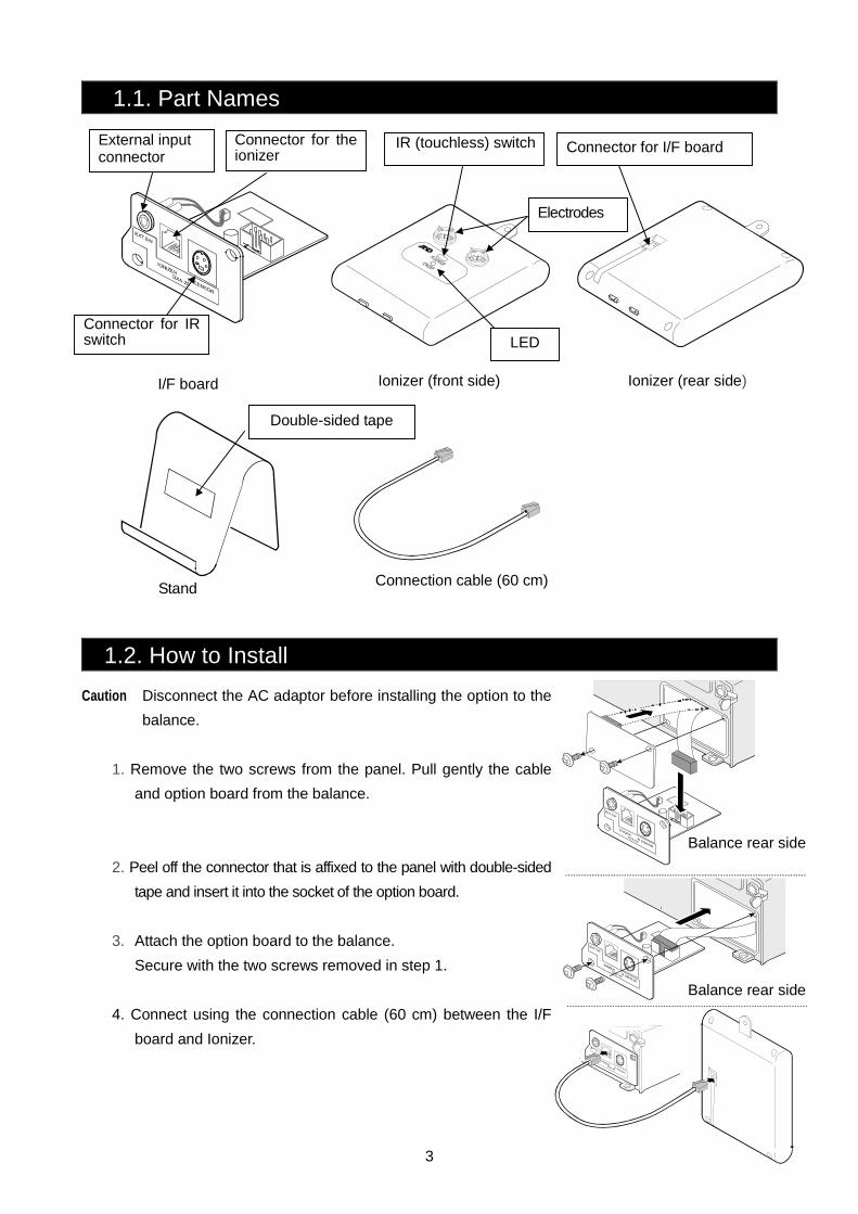
1.1. Part Names
I/F board
1.2. How to Install
Caution Disconnect the AC adaptor before installing the option to the
balance.
1. Remove the two screws from the panel. Pull gently the cable
and option board from the balance.
Balance rear side
2. Peel off the connector that is affixed to the panel with double-sided
tape and insert it into the socket of the option board.
3. Attach the option board to the balance.
Secure with the two screws removed in step 1.
Balance rear side
4. Connect using the connection cable (60 cm) between the I/F
board and Ionizer.
Connector for I/F board
Stand Connection cable (60 cm)
LED
IR (touchless) switchExternal input connector
Connector for theionizer
Ionizer (front side) Ionizer (rear side)
Connector for IR switch
Double-sided tape
Electrodes
4
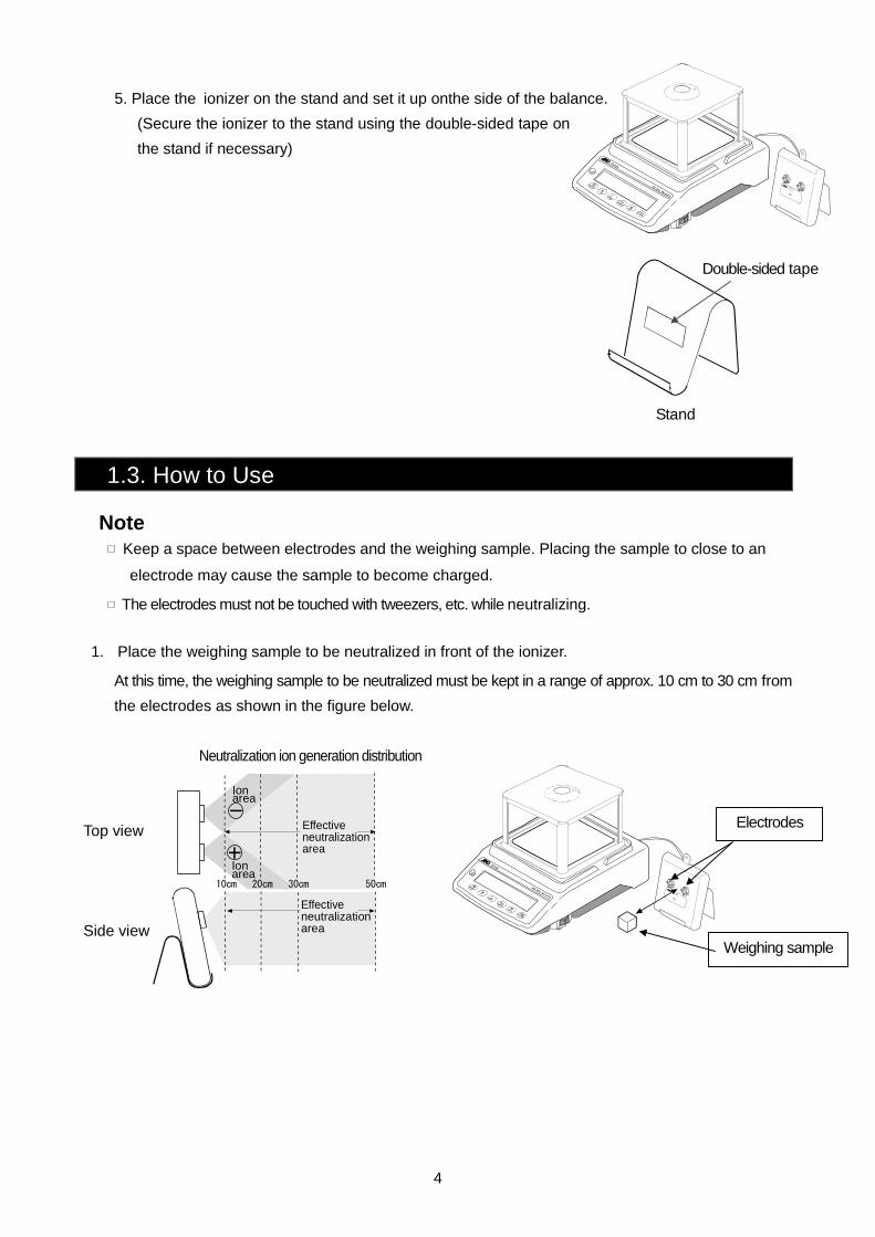
5. Place the ionizer on the stand and set it up onthe side of the balance.
(Secure the ionizer to the stand using the double-sided tape on
the stand if necessary)
1.3. How to Use
Note Keep a space between electrodes and the weighing sample. Placing the sample to close to an
electrode may cause the sample to become charged.
The electrodes must not be touched with tweezers, etc. while neutralizing.
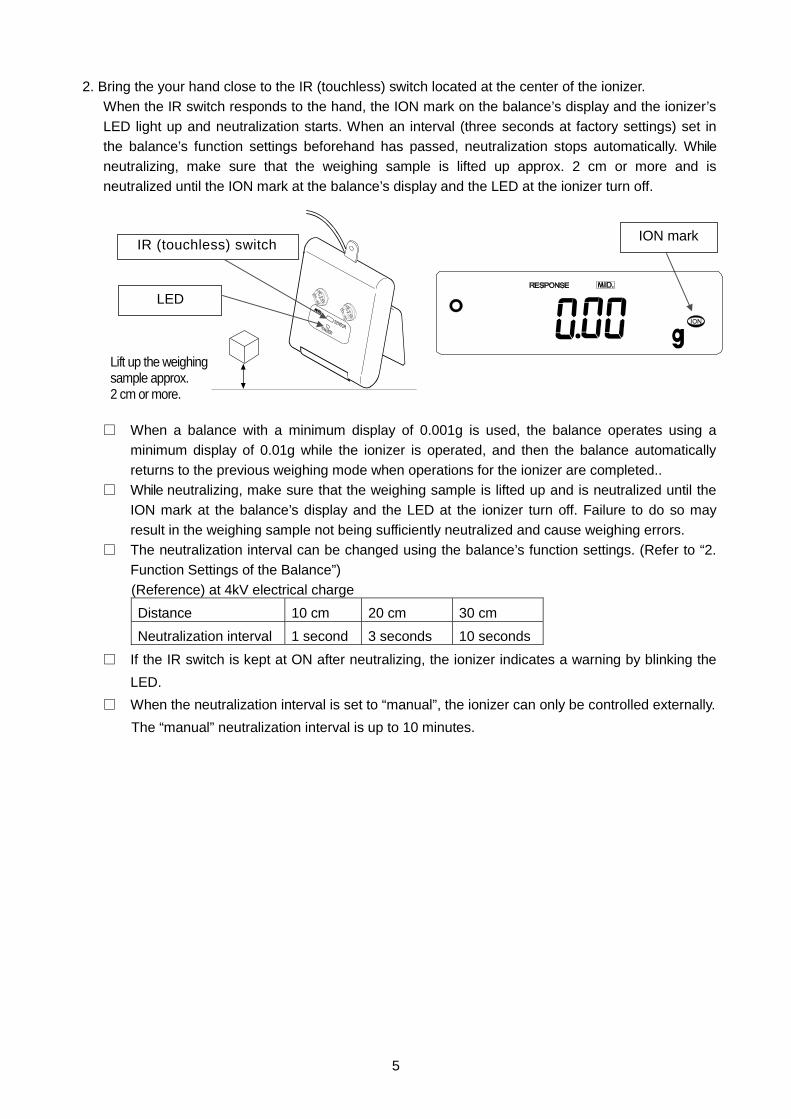
1. Place the weighing sample to be neutralized in front of the ionizer.
At this time, the weighing sample to be neutralized must be kept in a range of approx. 10 cm to 30 cm from
the electrodes as shown in the figure below.
Neutralization ion generation distribution
Top view
Side view
Weighing sample
Electrodes
Ionarea
10cm 20cm 30cm 50cm
Effectiveneutralizationarea
Effectiveneutralizationarea
Ionarea
Stand
Double-sided tape
5
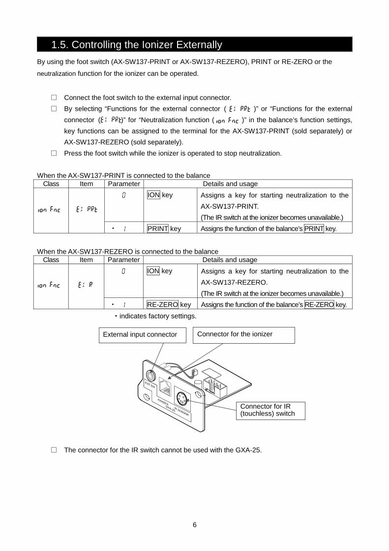
2. Bring the your hand close to the IR (touchless) switch located at the center of the ionizer.
When the IR switch responds to the hand, the ION mark on the balance’s display and the ionizer’s
LED light up and neutralization starts. When an interval (three seconds at factory settings) set in
the balance’s function settings beforehand has passed, neutralization stops automatically. While
neutralizing, make sure that the weighing sample is lifted up approx. 2 cm or more and is
neutralized until the ION mark at the balance’s display and the LED at the ionizer turn off.
Lift up the weighing sample approx. 2 cm or more.
□ When a balance with a minimum display of 0.001g is used, the balance operates using a
minimum display of 0.01g while the ionizer is operated, and then the balance automatically
returns to the previous weighing mode when operations for the ionizer are completed..
□ While neutralizing, make sure that the weighing sample is lifted up and is neutralized until the
ION mark at the balance’s display and the LED at the ionizer turn off. Failure to do so may
result in the weighing sample not being sufficiently neutralized and cause weighing errors.
□ The neutralization interval can be changed using the balance’s function settings. (Refer to “2.
Function Settings of the Balance”)
(Reference) at 4kV electrical charge
Distance 10 cm 20 cm 30 cm
Neutralization interval 1 second 3 seconds 10 seconds
□ If the IR switch is kept at ON after neutralizing, the ionizer indicates a warning by blinking the
LED.
□ When the neutralization interval is set to “manual”, the ionizer can only be controlled externally.
The “manual” neutralization interval is up to 10 minutes.
LED
ION mark IR (touchless) switch
6
1.5. Controlling the Ionizer Externally
By using the foot switch (AX-SW137-PRINT or AX-SW137-REZERO), PRINT or RE-ZERO or the
neutralization function for the ionizer can be operated.
□ Connect the foot switch to the external input connector.
□ By selecting “Functions for the external connector ( )” or “Functions for the external
connector ( )” for “Neutralization function ( )” in the balance’s function settings,
key functions can be assigned to the terminal for the AX-SW137-PRINT (sold separately) or
AX-SW137-REZERO (sold separately).
□ Press the foot switch while the ionizer is operated to stop neutralization.
When the AX-SW137-PRINT is connected to the balance Class Item Parameter Details and usage
0 ION key Assigns a key for starting neutralization to the
AX-SW137-PRINT.
(The IR switch at the ionizer becomes unavailable.)
1 PRINT key Assigns the function of the balance’s PRINT key.
When the AX-SW137-REZERO is connected to the balance Class Item Parameter Details and usage
0 ION key Assigns a key for starting neutralization to the
AX-SW137-REZERO.
(The IR switch at the ionizer becomes unavailable.)
1 RE-ZERO key Assigns the function of the balance’s RE-ZERO key.
・indicates factory settings.
□ The connector for the IR switch cannot be used with the GXA-25.
External input connector Connector for the ionizer
・
・
Connector for IR (touchless) switch
7
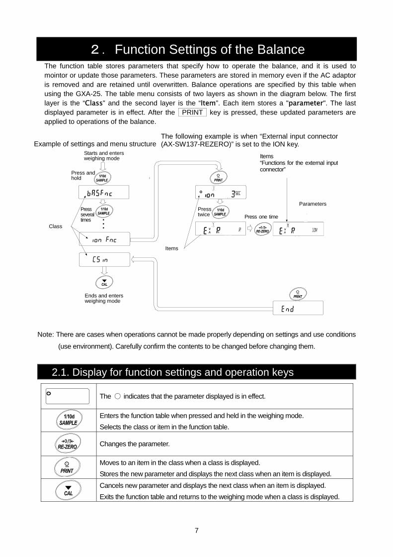
2.Function Settings of the Balance The function table stores parameters that specify how to operate the balance, and it is used to mointor or update those parameters. These parameters are stored in memory even if the AC adaptor is removed and are retained until overwritten. Balance operations are specified by this table when using the GXA-25. The table menu consists of two layers as shown in the diagram below. The first layer is the “Class” and the second layer is the “Item”. Each item stores a "parameter". The last displayed parameter is in effect. After the PRINT key is pressed, these updated parameters are applied to operations of the balance.
Example of settings and menu structure 「データメモリ機能」を「計
「インターバル時間」を「1分毎」に設定する例。
Note: There are cases when operations cannot be made properly depending on settings and use conditions
(use environment). Carefully confirm the contents to be changed before changing them.
2.1. Display for function settings and operation keys
The 〇 indicates that the parameter displayed is in effect.
Enters the function table when pressed and held in the weighing mode.
Selects the class or item in the function table.
Changes the parameter.
Moves to an item in the class when a class is displayed.
Stores the new parameter and displays the next class when an item is displayed. Cancels new parameter and displays the next class when an item is displayed.
Exits the function table and returns to the weighing mode when a class is displayed.
The following example is when “External input connector (AX-SW137-REZERO)” is set to the ION key.
ion fnc
lon 3
Press twice Press one time
exrR
C5in
Items “Functions for the external inputconnector”
Parameters
Items
Ends and enters weighing mode
Starts and enters weighing mode
Press and hold
Press several times
Class
8
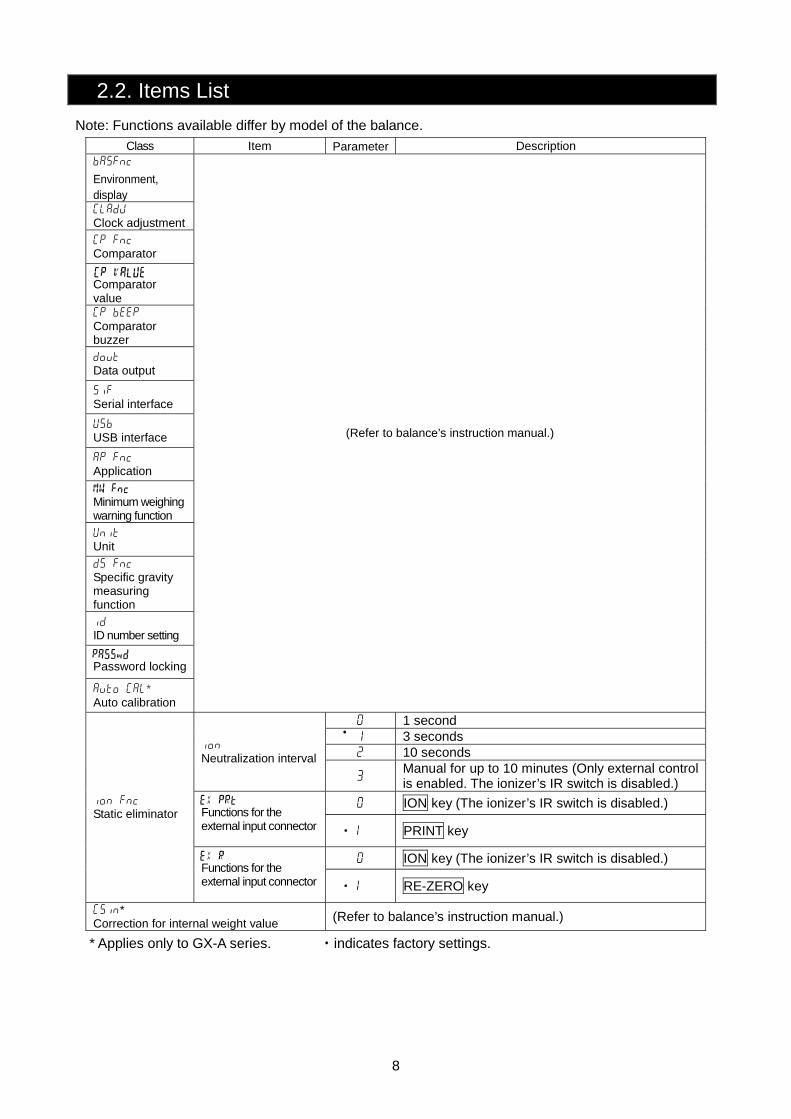
2.2. Items List
Note: Functions available differ by model of the balance.
Class Item Parameter Description ba5fnc
Environment, display CladjJ Clock adjustment
Cp fnc Comparator
Comparator value Cp beepEEP Comparator buzzer
dout Data output
5if Serial interface
U5b USB interface
ap fnc Application
Minimum weighing warning function
Unit Unit
d5 fnc Specific gravity measuring function
id ID number setting
Password locking
auto Cal* Auto calibration
(Refer to balance’s instruction manual.)
0 1 second 1 3 seconds 2 10 seconds
ion Neutralization interval
3 Manual for up to 10 minutes (Only external control is enabled. The ionizer’s IR switch is disabled.)
0 ION key (The ionizer’s IR switch is disabled.) Functions for the external input connector
・1 PRINT key
0 ION key (The ionizer’s IR switch is disabled.)
ion fnc Static eliminator
Functions for the external input connector
・1 RE-ZERO key
C5in* Correction for internal weight value (Refer to balance’s instruction manual.)
* Applies only to GX-A series. ・indicates factory settings.
・
9
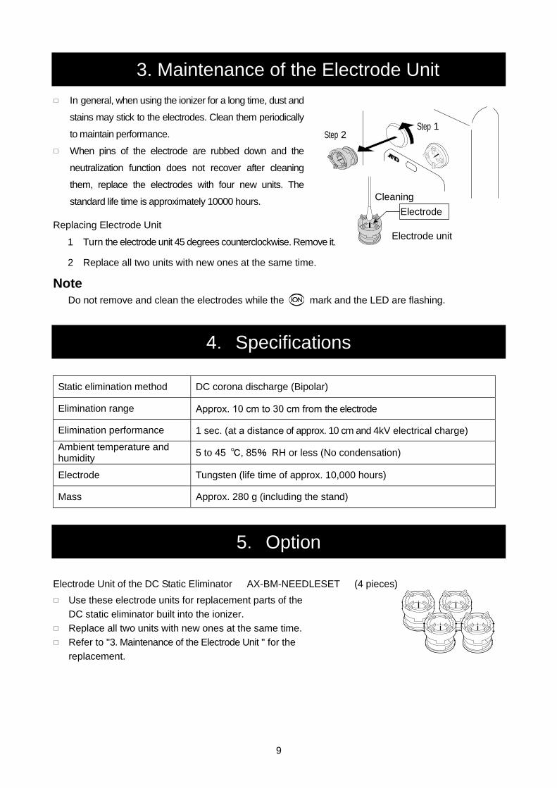
3. Maintenance of the Electrode Unit
In general, when using the ionizer for a long time, dust and
stains may stick to the electrodes. Clean them periodically
to maintain performance.
When pins of the electrode are rubbed down and the
neutralization function does not recover after cleaning
them, replace the electrodes with four new units. The
standard life time is approximately 10000 hours. Replacing Electrode Unit
1 Turn the electrode unit 45 degrees counterclockwise. Remove it.
2 Replace all two units with new ones at the same time.
Note Do not remove and clean the electrodes while the mark and the LED are flashing.
4.Specifications
Static elimination method DC corona discharge (Bipolar)
Elimination range Approx. 10 cm to 30 cm from the electrode
Elimination performance 1 sec. (at a distance of approx. 10 cm and 4kV electrical charge)
Ambient temperature and humidity
5 to 45 ℃, 85% RH or less (No condensation)
Electrode Tungsten (life time of approx. 10,000 hours)
Mass Approx. 280 g (including the stand)
5.Option
Electrode Unit of the DC Static Eliminator AX-BM-NEEDLESET (4 pieces)
Use these electrode units for replacement parts of the
DC static eliminator built into the ionizer.
Replace all two units with new ones at the same time.
Refer to "3. Maintenance of the Electrode Unit " for the
replacement.
Electrode unit
Step 1 Step 2
Cleaning
Electrode

MEMO

MEMO

MEMO

3-23-14 Higashi-Ikebukuro, Toshima-ku, Tokyo 170-0013, JAPAN Telephone: [81] (3) 5391-6132 Fax: [81] (3) 5391-6148 A&D ENGINEERING, INC. 1756 Automation Parkway, San Jose, California 95131, U.S.A. Telephone: [1] (408) 263-5333 Fax: [1] (408)263-0119 A&D INSTRUMENTS LIMITED Unit 24/26 Blacklands Way, Abingdon Business Park, Abingdon, Oxfordshire OX14 1DY United Kingdom Telephone: [44] (1235) 550420 Fax: [44] (1235) 550485 A&D AUSTRALASIA PTY LTD 32 Dew Street, Thebarton, South Australia 5031, AUSTRALIA Telephone: [61] (8) 8301-8100 Fax: [61] (8) 8352-7409 A&D KOREA Limited 한국에이.엔.디(주) 서울특별시 영등포구 국제금융로6길33 (여의도동) 맨하탄빌딩 817 우편 번호 150-749 ( 817, Manhattan Bldg., 33. Gukjegeumyung-ro 6-gil, Yeongdeungpo-gu, Seoul, 150-749 Korea ) 전화: [82] (2) 780-4101 팩스: [82] (2) 782-4280 OOO A&D RUS OOO "ЭЙ энд ДИ РУС" 121357, Российская Федерация, г.Москва, ул. Верейская, дом 17 ( Business-Center "Vereyskaya Plaza-2" 121357, Russian Federation, Moscow, Vereyskaya Street 17 ) тел.: [7] (495) 937-33-44 факс: [7] (495) 937-55-66 A&D INSTRUMENTS INDIA PRIVATE LIMITED
( 509, Udyog Vihar, Phase- , Gurgaon - 122 016, Haryana, India )
: 91-124-4715555 : 91-124-4715599
BackCover 1WMPD4000058M .
Recommended