GUIDELINES FOR CONSULTANTS
PERFORMING GEOTECHNICAL
INVESTIGATIONS
FOR
PROJECTS MAINTAINED BY
HARRIS COUNTY, TEXAS
EFFECTIVE DATE
JANUARY 1, 2011
Contents
Section I. Introduction
Section II. Applicability
Section III. Reconnaissance Geotechnical Studies
Section IV. Geotechnical Study
A. Field Investigation
B. Laboratory Testing
Section V. Engineering Analysis & Recommendations
Section VI. Geotechnical Report Format
APPENDECIES
Appendix “A” Reconnaissance Study Report Format
Appendix “B” Minimum Requirements for Frequency and
Depth of Borings
~ 1 ~
Section I – Introduction
These guidelines are to be used in order to implement a uniform approach to
geotechnical investigation and reporting for infrastructure to be designed for,
constructed on behalf of, or maintained by Harris County Texas. The intent is not
to supersede the engineering judgment of the consultant, but rather to define
minimum levels of effort, and establish the required report organization. Harris
County consists of 1778 square miles of land with varying soils, topography and
hydrologic conditions, so detailed geotechnical studies are required on most
projects.
Section II – Applicability
These guidelines are to be used on horizontal and vertical construction projects
where the ultimate infrastructure is to be maintained by Harris County. These
guidelines are not applicable when another agency such Harris County Flood
Control District will maintain the infrastructure, in which case, Harris County
Flood Control District’s guidelines should be applicable. Additionally, these
guidelines are not applicable if a project funding source such as TxDOT has
specific requirements that must be met in order to receive funding for the project,
in which case those requirements should be applicable. These guidelines are
also not applicable for soil studies conducted for onsite sewage facilities.
Where Harris County is not funding the geotechnical services, the
reconnaissance geotechnical study portion of the geotechnical investigation is
not required. On projects built by developers and accepted for maintenance by
Harris County, the guidelines and reporting standards outlined in the
“Regulations of Harris County for Approval and Acceptance of Infrastructure”
shall be followed. However, this document should guide the boring spacing,
depth, location, etc., of the geotechnical investigation.
~ 2 ~
Section III – Reconnaissance Geotechnical Studies
Upon written request by the County Engineer, the Consultant shall perform a
reconnaissance geotechnical study in general accordance with Appendix “A” of
the project alignment/project site.
The goals and objectives of reconnaissance studies generally include the
following:
1. Estimate what soil types are within the project area,
2. Identify the characteristics and properties of the soils present,
3. Use available soil characteristics, properties and potential project
geometrics to identify possible geotechnical concerns,
4. Review existing data including available fault maps,
5. Establish a geotechnical scope of services for the geotechnical study plan
(GSP) in general accordance with Appendix “B”, and
6. Make recommendations for any necessary variances to the approved
Harris County Geotechnical Guidelines.
The consultant shall submit a Reconnaissance Geotechnical Study Report,
stating the results of the reconnaissance study, to the County Engineer, along
with a request-to-proceed with the GSP. The format for the Reconnaissance
Study Report and a sample request-to-proceed with the GIP letter are found in
Appendix “A”.
Section IV – Geotechnical Study
Project Initiation
~ 3 ~
Immediately upon written notice, from the County Engineer, to proceed with the
GSP, the geotechnical consultant should begin their geotechnical study.
A. Field Investigation
The location and number of soil borings should be in accordance with the
approved GSP. The drilling equipment and sampling methods should be in
general accordance with the appropriate ASTM designations. If there is no
applicable ASTM designation, the drilling equipment and sampling methods
should generally be left to the discretion of the geotechnical engineering
consultant. The presentation format of the data in the report and in electronic
database must adhere to HCPID standards.
Boring Spacing, Depth, and Groundwater Observations
Soil boring and sampling should be conducted to obtain pertinent information
about the subsurface soil stratigraphy and groundwater conditions. The
minimum depth and frequency of borings are outlined in Appendix “B”. However,
the geotechnical consultant may recommend alternative boring spacing and
depths if justified, subject to the approval of the County Engineer. Borings
should be strategically located in the immediate vicinity of the area of interest and
away from any existing underlying or overhead utility lines.
The consultant should notify the County Engineer of any unusual conditions so
they can be addressed.
The depth at which groundwater is encountered during drilling should be
measured and recorded. Upon the completion of drilling and sampling, the
borehole should be covered to minimize the flow of surface water into the
borehole. About 24 hours after the boring has been drilled, the depth to
~ 4 ~
groundwater in the borehole and the depth to which the borehole is open should
be measured and recorded.
Sampling Methods and Intervals
Undisturbed samples should be generally recovered in cohesive soils using a
thin-walled metal tube sampler that complies with ASTM D1587 requirements.
For granular soils, Standard Penetration Split-Barrel samplers should be used in
general compliance with ASTM D1586 requirements. Continuous sampling
should be performed to a minimum depth of 15 feet, and at 5-foot intervals below
that depth. All drilling and sampling should generally comply with the appropriate
ASTM method.
Relevant Data and Format of Boring Logs and Data Files
Geographical locations and depths of borings and/or piezometers, date, weather
conditions, and methods of drilling should be recorded and shown on the boring
logs. Elevation data should be provided by the project surveyor and shown on
the boring logs relative to the survey datum for the project. Northing coordinates
(y coordinates) and easting coordinates (x coordinates) should also be provided
by the project surveyor and shown on the boring logs. Each boring must have
reference points or ties so that the location of the boring can be recovered. The
ties can be a distance to two or more permanent objects or x-y coordinates with a
recoverable reference point.
For granular materials, “blow counts” for the SPT samples should be recorded.
For cohesive soils, pocket penetrometer readings should be taken at the site
from undisturbed thin-wall tube samples. Soil descriptions should be based on
visual inspection of the samples and the requirements of ASTM D2488. Soil
descriptions should include texture, color, and inclusions such as nodules, stains,
organic materials, etc. Layer variations should be recorded when applicable.
The geotechnical engineering consultant should record the water bearing layers,
the depth to groundwater encountered during drilling, the depth to groundwater
~ 5 ~
about 24 hours after the completion of drilling, and the depth of the open
borehole about 24 hours after the completion of drilling. Piezometric water level
readings should be presented in tabular form with their corresponding reading
dates. Any unusual conditions such as perched water should be reported and
seasonal groundwater fluctuations should be noted.
Location Map and Soil Profile Drawings
A boring location map and soil profile drawing(s) should be included in the report.
The boring location map should be on sheets no larger than 11” X 17” and can
be constructed from a variety of sources such as Baca maps, ground surveys,
and USGS Quad maps. The boring location map should clearly show landmarks
such as cross streets, outfall channels, or any other permanent feature that can
be used to describe the location.
The soil profile drawing(s) should show the subsurface soil and groundwater
conditions along a line of borings for the full depth of the borings. The
geotechnical engineering consultant should provide a soil profile drawing for the
project alignment, so a reasonable representation of the subsurface soil and
groundwater conditions at the site is presented. This provision would not apply
to projects funded by developers, unless a major thoroughfare is proposed. If a
major thoroughfare is proposed only the area surrounding the major thoroughfare
shall be depicted in the drawings.
Environmental Concerns
Should environmental concerns be identified during geotechnical drilling and no
previous provisions for environmental sampling protocol have been provided in
the project scope, drilling should cease and the County should be notified. If the
project scope includes environmental protocol sampling, the geotechnical
engineering consultant is responsible for adhering to all pertinent federal, state,
and local regulations and laws.
~ 6 ~
Site Restoration
Where necessary, it is the responsibility of the geotechnical engineering
consultant to remove cuttings resulting from the geotechnical exploration upon
completion of drilling and sampling activities. In the case of borings through
pavements, similar or equivalent materials should be used to restore the site.
Backfilling of borings and sealing off piezometers should be conducted by using
non-shrink grout placed with a tremie pipe.
Piezometers
Temporary piezometers should be installed when included in the project scope.
The piezometers should be read at least 24-hours after initial installation and
periodically during 30 days after installation. Piezometers should be spaced no
further than 2,500 feet apart along underground utilities where water-bearing
layers (or potentially water-bearing layers) are encountered, unless otherwise
recommended by the geotechnical engineer and approved by the County
Engineer. Piezometers are to be abandoned in accordance with Texas
Commission on Environmental Quality (TCEQ) when they are no longer
necessary.
Fault Investigation
All projects requiring a geotechnical study should include, as a separate task, a
review of available existing fault maps and a field visit to identify any significant
visual fault activity along the project alignment or at the specific project site that
may have an impact on the design of the project.
A Phase I fault study should be performed in general accordance with the most
current version of Houston Geological Society (HGS) Bulletin technical article
entitled “Investigation of Surface Faults in Texas Gulf Coast Region” should be
performed, to confirm fault activity, if:
~ 7 ~
1.) The review of fault maps and/or field reconnaissance identified potential fault
activity,
2.) It is recommended by the geotechnical engineer, and
3.) It is approved by the County Engineer.
If the results of the Phase I study show sufficient evidence of the presence of a
fault that could potentially impact the project site, a Phase II study should be
undertaken as described in the above-referenced most current HGS Bulletin and
approved by the County Engineer. A Phase II study requires the collection and
analysis of existing geophysical logs and/or the drilling and logging of
geophysical borings.
If the Phase II study establishes the presence of a fault at the project site, a
topographic survey should be performed and additional geophysical borings
drilled/logged as part of a Phase III fault study as required by the above-
referenced HGS Bulletin and approved by the County Engineer. The location
and width of the fault zone, strike, and dip of the fault should be determined.
Prediction of the movement of the fault should be formulated and the impact of
fault activity on site structures should be assessed. Detailed fault studies are
most applicable to development of buildings or other structures and less
applicable to standard road sections where fault damage can be repaired
inexpensively.
B. Laboratory Testing
General Requirements and Standards
The purpose of the laboratory testing program is to define the soil classification,
soil stratigraphy, and the relevant engineering properties of the encountered
soils. Laboratory analysis testing should be conducted and combined with
geologic information to classify the soils and determine the stratification. The
~ 8 ~
selection of appropriate laboratory testsis left to the discretion of the geotechnical
engineering consultant. The approved laboratory testing program should
outlined in the Geotechnical Study Plan (GSP) and must be approved by the
County Engineer.
Laboratory testing should be conducted in general accordance with the
corresponding ASTM standards. Standards other than ASTM standards may be
used only with the approval of the County Engineer.
Description and Classification of Soils
The subsurface stratification should be clearly defined and soils should be
classified according to the appropriate ASTM standards and to laboratory
classification tests. Wherever a soil sample or soil type is referenced in the
report, the ASTM group name and symbol should be provided. The County
requires that the boring log soil descriptions be in the order of the ASTM
classification and group symbol [e.g. Fat Clay (CH)], followed by the consistency
[e.g. stiff, very stiff, loose, etc], followed by a descriptor for plasticity [e.g. slight
plasticity, highly plastic, etc],followed by the color, followed by a description of the
moisture conditions. The consistency of cohesive soils should be described as
very soft, soft, firm, stiff, very stiff, or hard. The relative density of cohesionless
soils including silts shall be described as very loose, loose, medium dense,
dense, and very dense. Soil group name and consistency should also be shown
on soil profiles taken through the boring locations so as to represent the site
subsurface soil conditions.
Minimum Series of Tests
Relevant soil parameters should be given for every layer. These parameters
include strength data, classification test results, and moisture content. For
cohesive soils, Atterberg limits, dry density, strength tests, and minus 200 sieve
tests should all be performed on at least one sample within each distinct layer.
For granular soils, minus 200 sieve tests should be conducted on at least one
sample. Engineering properties such as shear strength can be estimated using
~ 9 ~
pocket penetrometer and/or torvane tests for cohesive soils and SPT blow counts
for granular soils.
Section V - Engineering Analysis and Recommendations
The goal of the engineering analyses is to provide geotechnical information to
guide the design of the project and address conditions anticipated during
construction. This information should be an interpretation of the field and
laboratory data applied to the specific conditions and purpose of the project.
Design information may include recommendations for pavement type, thickness
and reinforcement, subgrade treatment alternatives, acceptable foundation types
and design criteria. Constraints on the design will be given by the County
Engineer on projects commissioned by Harris County.
Section VI – Geotechnical Report Format
The geotechnical report should be in general compliance with the following
format.
Transmittal letter with Professional Engineer’s seal and approval signatures.
EXECUTIVE SUMMARY
INTRODUCTION
Name of department and person authorizing the report
Date of authorization
Brief background information about the project
PURPOSE & SCOPE OF WORK
Description of the work to be done in the report
Reiteration of scope of work
~ 10 ~
Description of the proposed facilities including type, length, and other detailed
descriptions.
SITE EXPLORATION
Physical description of area
Geology
FIELD WORK
Soil borings and sampling
Piezometer installation (If applicable)
Environmental issues (If applicable)
LABORATORY TESTING
DESCRIPTION OF SUBSURFACE SOIL AND GROUNDWATER CONDITIONS
Description of soil stratigraphy
Description of groundwater conditions
Description of soil properties
ENGINEERING ANALYSIS AND RECOMMENDATIONS
Description of engineering methods & assumptions
Pavement analyses (If applicable)
Subgrade treatment recommendations (If applicable)
Drilled shaft and driven pile analysis (If applicable)
CONSTRUCTION CONSIDERATIONS
APPENDICES
Site Vicinity Map
Plan of Borings
Laboratory Test Results
Boring Logs
Soil Profile Drawings Showing Soil and Groundwater conditions
Engineering Data
Boring Logs
Applicable engineering analysis output
Geologic Fault Study (as a separate study)

~ 11 ~
APPENDICES
~ 12 ~
Appendix “A”
Reconnaissance Study Report Format
Title Page – Project Name, APIN Number (County Projects Only),
Preliminary Investigative Report, Consulting Firms Name, Address and
Date, and Engineer’s seal
Table of Contents
Summary of soils likely to be within project area
Discussion of potential problematic areas due to project type
Discussion of findings from “tabletop” format evaluation
Outline of Geotechnical Study Plan (GSP) including recommended testing
type, boring depth, and frequency
Justification for any additional geotechnical studies and/or testing in
excess of that prescribed in the “Guidelines for Consultants Performing
Geotechnical Investigation on Behalf of Harris County, Texas”.
11” X 17” Map outlining proposed boring locations and depth in
relationship to the project.
11” X 17” Map outlining project area on the soil survey of Harris County,
and delineating the various surface soils.
~ 13 ~
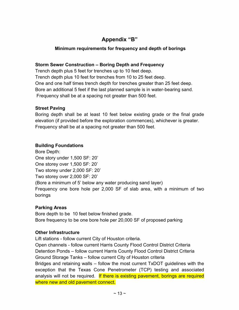
Appendix “B”
Minimum requirements for frequency and depth of borings
Storm Sewer Construction – Boring Depth and Frequency
Trench depth plus 5 feet for trenches up to 10 feet deep.
Trench depth plus 10 feet for trenches from 10 to 25 feet deep.
One and one half times trench depth for trenches greater than 25 feet deep.
Bore an additional 5 feet if the last planned sample is in water-bearing sand.
Frequency shall be at a spacing not greater than 500 feet.
Street Paving
Boring depth shall be at least 10 feet below existing grade or the final grade
elevation (if provided before the exploration commences), whichever is greater.
Frequency shall be at a spacing not greater than 500 feet.
Building Foundations
Bore Depth:
One story under 1,500 SF: 20’
One storey over 1,500 SF: 20’
Two storey under 2,000 SF: 20’
Two storey over 2,000 SF: 20’
(Bore a minimum of 5’ below any water producing sand layer)
Frequency one bore hole per 2,000 SF of slab area, with a minimum of two
borings
Parking Areas
Bore depth to be 10 feet below finished grade.
Bore frequency to be one bore hole per 20,000 SF of proposed parking
Other Infrastructure
Lift stations - follow current City of Houston criteria.
Open channels - follow current Harris County Flood Control District Criteria
Detention Ponds – follow current Harris County Flood Control District Criteria
Ground Storage Tanks – follow current City of Houston criteria
Bridges and retaining walls – follow the most current TxDOT guidelines with the
exception that the Texas Cone Penetrometer (TCP) testing and associated
analysis will not be required. If there is existing pavement, borings are required
where new and old pavement connect.
~ 14 ~
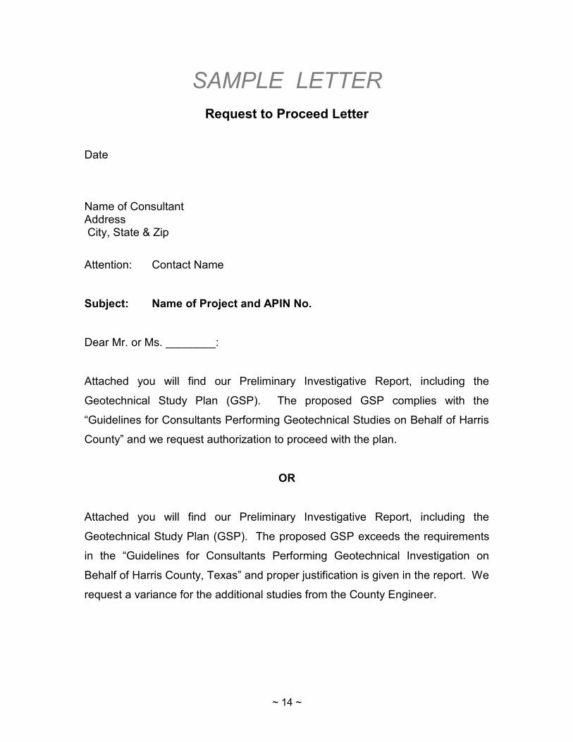
SAMPLE LETTER
Request to Proceed Letter
Date Name of Consultant Address City, State & Zip
Attention: Contact Name
Subject: Name of Project and APIN No.
Dear Mr. or Ms. ________:
Attached you will find our Preliminary Investigative Report, including the
Geotechnical Study Plan (GSP). The proposed GSP complies with the
“Guidelines for Consultants Performing Geotechnical Studies on Behalf of Harris
County” and we request authorization to proceed with the plan.
OR
Attached you will find our Preliminary Investigative Report, including the
Geotechnical Study Plan (GSP). The proposed GSP exceeds the requirements
in the “Guidelines for Consultants Performing Geotechnical Investigation on
Behalf of Harris County, Texas” and proper justification is given in the report. We
request a variance for the additional studies from the County Engineer.
Recommended