Soldagem & Inspeção. 2016;21(3):290-302http://dx.doi.org/10.1590/0104-9224/SI2103.05
Technical Papers
This is an Open Access article distributed under the terms of the Creative Commons Attribution Non-Commercial License which permits unrestricted non-commercial use, distribution, and reproduction in any medium provided the original work is properly cited.
Received: 26 Feb., 2016 Accepted: 17 June, 2016
*E-mails: [email protected] (JAA), [email protected] (AJR)
Abstract: Fracture mechanics approach is important for all mechanical and civil projects that might involve cracks in metallic materials, and especially for those using welding as a structural joining process. This methodology can enhance not only the design but also the service life of the structures being constructed. This paper includes detailed consideration of several practical issues related to the experimental procedures to assess the fracture toughness in high strength low alloy steels (HSLA) using the crack tip opening displacement (CTOD) parameter, specifically pipeline steels for oil and gas transportation. These considerations are important for engineers who are new in the field, or for those looking for guidelines performing different procedures during the experimentation, which usually are difficult to understand from the conventional standards. We discuss on topics including geometry selection, number of replicate tests, fatigue precracking, test procedure selection and realization, reports of results and other aspects.
Key-words: CTOD; Experimental evaluation; Fracture toughness; HSLA steel; Pipeline steels.
1. Introduction
Selection of a fracture toughness parameter and type of specimen to assess materials with elasto-plastic behavior, such API-5L steels and different HSLA steels, depends on the level of approximation of the test conditions to a hypothetical crack in the actual structure. Aspects such as geometry of the specimen, load application, environmental and mechanical properties are the key factors to perform fracture toughness tests. CTOD and J-integral are the most common parameters used in the industry because the tests are practical and the methods are standardized [1]. These tests are conducted regularly on precracked specimens, where the initial state of the crack front might represents an actual or hypothetical crack in any structure element.
Regarding the reproducibility of real work conditions of a structure in lab conditions, the definition of the stress-strain state at the crack tip (or constraint) is fundamental to properly assess the fracture toughness [2], because it is basically the experimental assumption of how the stress is working in a real structure. That issue has been sorted by using different standardized specimens, the available technical standards offers different geometries and load modes, such as bending or tensile configurations. In addition, it is usual to find that those specimens offer a high constraint state and consider a crack growth under the plane-strain condition [3-6]. Although cracks in real structures do not always fulfill the requesting standard conditions, for example, residual stresses induced by welding procedures could change the constraint state and cause uneven fatigue cracks fronts [7,8], very shallow cracks are not considered standard, and some constraint conditions are far away from the options presented by the standards [9].
Even though it is not often used in the engineering projects, the core of fracture mechanics as we know was developed during the 1970s through the first part of the 1980s [10]. The bibliography on fracture mechanics is long, many important reviews have been published [2,10,11], books have been written addressing theoretical and experimental approach [12-14], and classic literature has also focused on the experimental assessment of welded structure [15]. A new user might struggle with problems associated with the proper selection of the geometry of the specimen, test preparation and testing, as well
Guide for Recommended Practices to Perform Crack Tip Opening Displacement Tests in High Strength Low Alloy SteelsJulián A. Ávila1,2*, Vinicius Lima2, Cassius O. F. T. Ruchert3, Paulo Roberto Mei1, Antonio J. Ramirez1,2,4
1 Universidade Estadual de Campinas – UNICAMP, School of Mechanical Engineering, Campinas, SP, Brazil.2 BrazilianNanotechnologyNationalLaboratory,Campinas,SP,Brazil.3 Universidade de São Paulo – USP, School of Engineering, São Carlos, SP, Brazil.4 The Ohio State University, Columbus, OH, USA.
Soldagem & Inspeção. 2016;21(3):290-302 291
Guide for Recommended Practices to Perform Crack Tip Opening Displacement Tests in High Strength Low Alloy Steels
as results interpretation. The aim of this guide is to present procedures from the experimental viewpoint, where different problems-solutions have been addressed in order to properly perform a fracture toughness assessment using the CTOD parameter.
2. Guidelines
2.1. Initial considerations
The BS-EN-ISO-15653 standard [8], at item 6.3 presents a flow diagram for performing the fracture toughness test. It starts by defining the interest region of study, followed by the selection of the specimen which better represents the constraint of the real application and finally, the choice of the direction, sense and depth of the initial notch.
The rate of invalid specimens can be about 10 to 15% of the total number. In order to decrease that rate, it is recommended to perform a preliminary matrix of tests which allows early correction of the problems. Most of the difficulties are related to the unknown fatigue crack and test parameters for each kind of material or welding conditions. Other problems are related to incorrect position of the specimen on the fixtures, improper adjustment of the fixtures or sensors, incorrect specimen sizing, excessive brittle or plastic behavior and residual stresses.
2.2. Number of tests
FortheresistancecurvesΔa-R,6specimens ineachevaluatedconditionareneeded.TheDNV-OS-F101standard [16] recommends three repetitions of each evaluated condition for the CTOD, J and KIC parameters; if one of the three results is unsatisfactory, performing more 3 tests is recommended, then choosing the lowest result from the 5 results as the critical one [17]. The BS-7910 standard [18], item 7.1.5.6, recommends for levels 2 and 3 assessments for CTOD and the critical stress intensity factor (KIC), use of the minimum value of three tests as the materials toughness. More detailed and statistical data treatment can be found in Annex k of the same standard [18].
2.3. Geometries of specimen
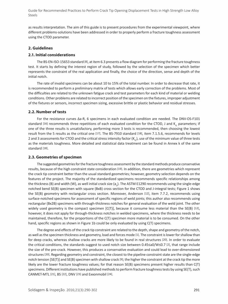
The suggested geometries for the fracture toughness assessment by the standard methods produce conservative results, because of the high constraint state consideration [19]. In addition, there are geometries which represent the crack tip constraint better than the usual standard geometries; however, geometry selection depends on the features of the project. The majority of the standardized specimens recommends specific relationships among the thickness (B) and width (W), as well initial crack size (a0). The ASTM E1290 recommends using the single-edge notched bend SE(B) specimen with square (BxB) cross section for the CTOD and J-integral tests; Figure 1 shows the SE(B) geometry with rectangular cross section. Moreover, Anderson [12], item 7.7.2, recommends using surface-notched specimens for assessment of specific regions of weld joints; this author also recommends using rectangular (Bx2B) specimens with through-thickness notches for general evaluation of the weld joint. The other widely used geometry is the compact specimen [C(T)], because it consume less material than the SE(B) [12], however, it does not apply for through-thickness notches in welded specimens, where the thickness needs to be maintained, therefore, for the proportions of the C(T) specimen more material is to be consumed. On the other hand, specific regions as shown in Figure 1b could be only evaluated by using C(T) specimens.
The degree and effects of the crack tip constraint are related to the depth, shape and geometry of the notch, as well as the specimen thickness and geometry, load and forces mode [1]. The constraint is lower for shallow than for deep cracks, whereas shallow cracks are more likely to be found in real structures [20]. In order to evaluate thecriticalconditions,thestandardssuggesttousednotchsizebetween0.45≤a0/W≤0.7[2], that range include the size of the pre-crack. However, this produces a conservative evaluation and could lead to over-dimensioned structures [20]. Regarding geometry and constraint, the closest to the pipeline constraint state are the single-edge notch tension [SE(T)] and SE(B) specimen with shallow crack [9]; the higher the constraint at the crack tip the more likely are the lower fracture toughness values; for that reason SE(B) specimens present higher results than C(T) specimens. Different institutions have published methods to perform fracture toughness tests by using SE(T), such CANMET-MTL [21], BS [22], DNV [23] and Exxonmobil [24].
Ávila et al.
292 Soldagem & Inspeção. 2016;21(3):290-302
None of the conventional geometries have been designed for multiple purposes, e.g., Castelluccio et al. [25] used mini SE(B) specimens to perform CTOD in-situ test in a scanning electron microscope (SEM), where notches were located at the heat affected zone (HAZ) of a fusion weld; Chan [26] performed a similar test with zircon. In addition, Koo et al. [19] studied the fracture toughness in a real size structures, where the tests were performed in a SA312 TP304L tube submitted to bending in 4 point-supports. They found close agreement between the results of finite elements simulations and the experimental assessment. Qian et al. [27] assessed the fracture toughness using J-integral in C(T) specimens and real size tube-joint with cross shape (356 mm in diameter), and found approximate agreement between the simulated model and the experimental results; a failure analysis diagram (FAD) was built with the test data.
2.4. Notch position and configuration
Notch position and configuration depend on the objective of the test; firstly, the shape and process origin of the material (plate, tube, square or rectangular bars) is defined, rolling direction and the regions of interest in the welded joint. The BS-7448 part II standard [4] presents two notch configurations for weld joints assessment. The first one is the weld positional (WP), which is recommended for assessing general weld regions and which regularly uses rectangular cross section (Bx2B) specimens, with notches through-thickness. The second is named specific microstructure (SM) and is recommended to assess localized regions within the weld joint [15]; the latest notch configuration commonly uses square cross section specimens. The standards ASTM-E399-09 item 3.1.3 [28], ISO-12135 item 5.4.2.3 [29], and BS-EN-ISO-15653 [8], item 6.3, present different notches identification systems.
Regarding welded joints, the notch must guarantee that the crack or pre-crack tip growth thought the microstructure of interest [30,31]. Assessment of welded joints is challenging, since within the weld joints there are several different microstructural regions, all close to the others, so that a badly positioned notch could lead to wrong results [32-34]. The critical zone in fusion welds is the HAZ, because heterogeneities of this region imply
Figure 1. API X80 steel two-passes FSW joint, SE(B) specimen submitted to CTOD test at 25 °C, 15 mm thickness. (a) Specimen geometry and dimensions (mm); crack surface: (b) Non residual stress relief; (c) local compression using device type C from BS-EN-ISO 15653 [8] standard and (d) Local compression plus side grooves, 10% of the thickness deep in each side.
Soldagem & Inspeção. 2016;21(3):290-302 293
Guide for Recommended Practices to Perform Crack Tip Opening Displacement Tests in High Strength Low Alloy Steels
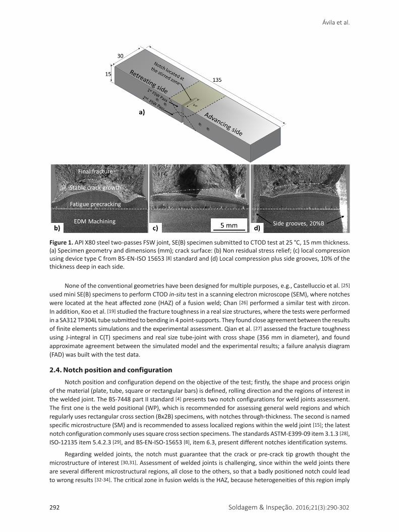
that toughness evaluation criteria do not comply with the standards [25]. Most of the brittle regions are located at the HAZ [35], therefore, there are some suitable options to assess these regions, e.g., joints with “V” or “K” shapes, where one of the sides is perpendicular to the plate surface [25,36,37]. As show in the schematic weld joint cross view in a Figure 2a, b, for both “V” symmetrical shape and K shapes, the HAZ could be evaluated using compact miniaturized specimens. The specimen must presents a size that fits with the available material, however, if the material presents a high plastic behavior the miniaturized specimen could not present a complete strain plane state at the crack front, thus the test could not meet the standards requirements for straightness of the crack front., i.e., Chludzinski [38] used small compact size in order to assess CTOD in a HAZ from a FSW joint with success. In an internal report [39], SE(B) square specimens of 9Ni delivered reliable information.
2.5. Crack size measurement techniques
There are several experimental methods to measure the crack growth during the CTOD test, where the most common, easy-to-use, and the cheapest method is the clip gauges; those sensors are mounted in the crack mouth (notch), and they are capable of measuring the crack mouth opening displacement (CMOD). After the test, it is necessary to process the measured results for applied force and CMOD to determine the KIC, CTOD or J-integral value.
Another measurement method is the CTOD90 (orδ90), which uses two-clip gauges and allow to measure directly the CTOD [40,41], this technique is explained at the DNV-OS-F101 [16] standard. In addition, the test fixtures configurations might allow using clip gauges in liquid medium, as long as the clip gauge maintains its position over the solution, such as Silva [32] who performed CTOD tests in low temperatures using a cooled bath composed by alcohol and dry ice.
Figure 2. Notches design options to assess the HAZ in fusion weld joints, C(T) specimens: (a, b); (c) SE(B) specimen [39].
Ávila et al.
294 Soldagem & Inspeção. 2016;21(3):290-302
For different testing environments in which the clip gauges could not be use, such corrosive environments, there are different options; e.g., the CTOD5(orδ5) uses two reference points with a span of 5 mm between them, and the measurement could be done by using digital image correlation (DIC) [42]. The separate DIC technique is also available to measure the crack opening, where a system of CCD cameras is used to acquire images during the whole test, however, it is out of range for depth notches [42-45]. Another technique for ruinous environments is the electrical potential drop technique, which allows following the crack growth in the specimen by introducing a constant current, which measures the variation in potential (V) while the crack is growing [42].
Another indirect method to measure CTOD is the silicone notch replication by silicone rubber infiltration method [46], nevertheless, the results determined that using this technique was not close to the clip gauges results [46]. However, this technique could be applied to preliminary testing, when is not possible to determine the real crack front shape. In order comply with standards requirements, knowing the shape and depth of the crack front in the early stage in the precracking might allow procedures modification if necessary, which could reduce the rate of invalidated samples results. Measurements from a linear variable differential transformer (LVDT) also provide good results and are explained in [12].
2.6 Precracking procedure
The aim of precracking is to simulate a real crack in a structure, so it should be narrow and deep enough to avoid effects of the machined notch. The fracture toughness test is performed after the specimen precracking. For the notch it is recommended to use electric discharge machining (EDM), as it does not affect the region around the notch [47] and offers an easier way to start a crack by fatigue; depending on the material the precracking procedure could be avoided [28,48]. In order to follow the crack growth by naked eye it is recommended to grind and polish the side surfaces. In addition, transverse, equally spaced t marks (lines) should be made to identify the size of the crack during precracking. It is important to point out that the minimum fatigue precrack extent is 0.05 B or 1.3 mm [6]. There are three important crack- size stages: 1) machined notch size (am), 2) initial crack size (a0), created most of the time by using fatigue, and 3) the final crack size after the toughness test (ap).
The number of cycles required to perform the fatigue precracking depends on the temperature, specimen size and geometry, material, residual stresses, machined notch radius, load ratio (R=Pmin/Pmax) and stress-intensity factor (KIC). If for any reason the crack initial condition deviates from the intended, the result could be unrepresentative of the region of interest, therefore it could lead to an erroneous interpretation of the results. According to the standards, the precracking should be done in conditions similar to the studied conditions, e.g., it is advisable to avoid aggressive environments, high or low temperatures, high load values and fatigue frequency less than 100 Hz [6]. Excessive applied load during the precracking accelerates the crack growth; nevertheless, it creates a bigger plastic region in front of the crack tip. Using standard load equations to determine a proper load value [6] is recommended, in addition to increasing the frequency as much the machine allows it.
Duringpreliminarytests,itisimportanttodeterminetheload/frequencyconfigurationforeachgeometrywhere the machine performs the commanded loads for each cycle, which could be achieved by doing a real-time graph of the behavior of the commanded and applying loads; typically the frequency values are between 20-40 Hz. The conventional procedure recommends using two steps to grow the crack, the first part is performed by using high loads until the crack gets to 50% of its total depth, and then load is reduced (~50%) and maintained steady until the crack reaches the final size. More information about force and intensity factor (K) limits and, crack size in each stage could be access in [6,49]. An alternative method uses a gradually decremented load, which could be better than the former one because it may require less participation from the user. The effect of the stress intensityfactor,limitload,stressratioandΔKmax during the precracking over the fracture toughness have been studied elsewhere [50].
2.7. Weldment samples precracking
The influence of residual stresses of weld joints during the precracking is large, because of low stresses used during the fatigue procedure. Measurements of residual stresses in FSW welded joints in steel have shown variation between tensile and compressive residual stresses distribution [51,52]. Furthermore, residual stresses also change the crack tip constraint because there is an interaction between external loads being applied and internal stresses due to residual stresses, consequently it could produces uneven fatigue crack fronts [7,8]. The authors have found
Soldagem & Inspeção. 2016;21(3):290-302 295
Guide for Recommended Practices to Perform Crack Tip Opening Displacement Tests in High Strength Low Alloy Steels
in a friction stir welding specimens without residual stress modification, in which the number of cycles during precracking was higher (60-90%) than the base material condition. The higher the residual stresses the larger the fracture toughness [53]; however, it is important to point out that compressive and tensile residual stresses provide respectively high or low fracture toughness values [54].
Regarding weld joint evaluation, one of the recurrent problems is the tunneling of the crack front because of the residual stresses state, which leads to excessive differences between the crack growth at the specimen center and its sides, while the difference between the maximum and minimum crack size must be less than 10% ASTM-E1290 [3]. Likewise, the BS-EN-ISO-15653 [8] standard allows 20% of different for weld joints. A tunneling (uneven) crack front would growth in a mix of loading modes, however all the standards present equations only for opening mode (mode I), therefore, those fracture toughness results do not comply the standard requirements. Fracture toughness resulting from tunneling crack fronts could lead to overestimation of fracture toughness and diminish the crack growth [30]. The option to assess fracture toughness with initial cracks (a0) presenting large tunneling should be well reported and justified. Sometimes, in experimental researches, is important to know how the crack grows in real conditions.
There are options to modify the residual stresses in weld joint specimens, e.g., BS-EN-ISO-15653 [8] recommends to perform local compression over the crack growth path, and to use a load ratio of 0.5 (R) when it is commonly 0.1. After precracking, side grooves could be machined with the root over the crack path. This procedure cuts out part of the crack front and leaves a straighter crack front. In many cases, no single procedure overcomes the problem; therefore, it is necessary to use a mixture of them. The side groove depth should not exceed 25% of thickness (BN) [6]. Fracture toughness for API X70 could be reduced 18% when machined side grooves [55], and 20-24% for API X60 and API X70 steels [56].
Local compression over the lateral sides of the crack path is recommended to modify the residual stress state in fracture toughness specimens [7]; however, the fracture toughness could be reduced by using this method [57]. However, this is the best option available to modify the residual stresses [12]. Meith et al. [7] concluded that fracture toughness depends more on the position of the local compression than on its magnitude. In addition, strain less than 5% did not affect the rolling direction (L-T) notches in API X65 steel, but it did in the transverse direction (T-L) [58]. In the BS-EN-ISO 15653 [8] standard, item C.2, there are three suggested devices to perform the local compression. The applied load depends of the chosen device, thickness and the geometry of the specimen, and yield stress of the material.
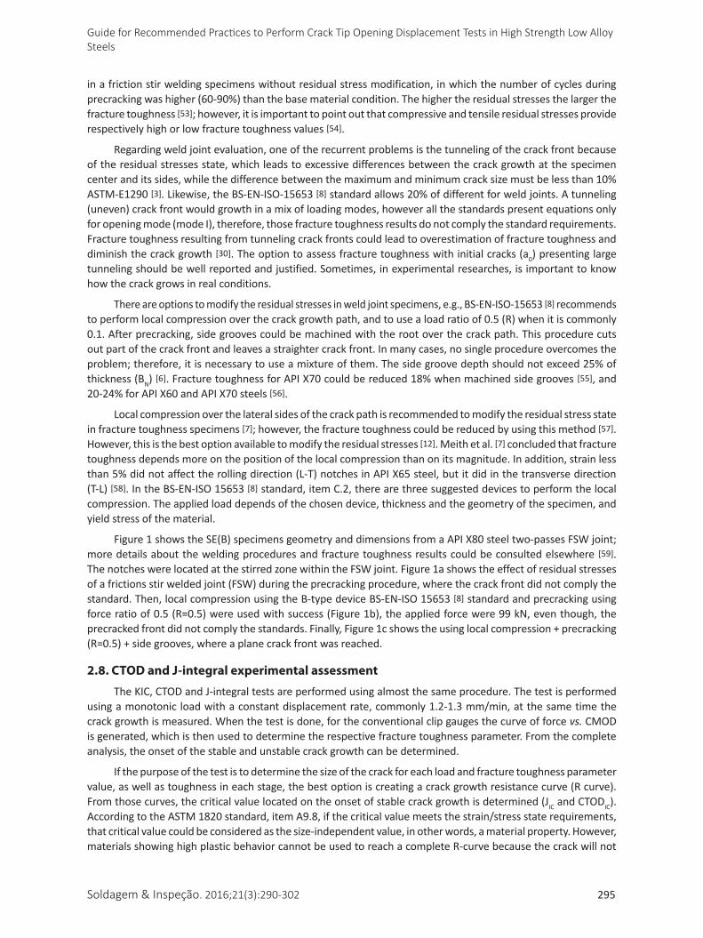
Figure 1 shows the SE(B) specimens geometry and dimensions from a API X80 steel two-passes FSW joint; more details about the welding procedures and fracture toughness results could be consulted elsewhere [59]. The notches were located at the stirred zone within the FSW joint. Figure 1a shows the effect of residual stresses of a frictions stir welded joint (FSW) during the precracking procedure, where the crack front did not comply the standard. Then, local compression using the B-type device BS-EN-ISO 15653 [8] standard and precracking using force ratio of 0.5 (R=0.5) were used with success (Figure 1b), the applied force were 99 kN, even though, the precracked front did not comply the standards. Finally, Figure 1c shows the using local compression + precracking (R=0.5) + side grooves, where a plane crack front was reached.
2.8. CTOD and J-integral experimental assessment
The KIC, CTOD and J-integral tests are performed using almost the same procedure. The test is performed usingamonotonic loadwithaconstantdisplacementrate,commonly1.2-1.3mm/min,atthesametimethecrack growth is measured. When the test is done, for the conventional clip gauges the curve of force vs. CMOD is generated, which is then used to determine the respective fracture toughness parameter. From the complete analysis, the onset of the stable and unstable crack growth can be determined.
If the purpose of the test is to determine the size of the crack for each load and fracture toughness parameter value, as well as toughness in each stage, the best option is creating a crack growth resistance curve (R curve). From those curves, the critical value located on the onset of stable crack growth is determined (JIC and CTODIC). AccordingtotheASTM1820standard,itemA9.8,ifthecriticalvaluemeetsthestrain/stressstaterequirements,that critical value could be considered as the size-independent value, in other words, a material property. However, materials showing high plastic behavior cannot be used to reach a complete R-curve because the crack will not
Ávila et al.
296 Soldagem & Inspeção. 2016;21(3):290-302
grow. This problem is exacerbated when testing thin pipeline [30,60,61]. A complete experimental description of the R-curve is reported in chapter 7 of [12].
During the fracture toughness test it is recommended to use the closest temperature possible to the real application. With decreasing temperature, most of the metals increase the constraint at the crack tip because of the suppression of the plastic deformation mechanism under low-temperature conditions; hence, in such materials the likelihood of cleavage increases with decreasing temperature. The fracture toughness depends of thickness at the ductile-brittle transition region, and thick specimens presented lower toughness than thin specimens; therefore it is not safe to predict fracture toughness in that region by using thin specimens [62].
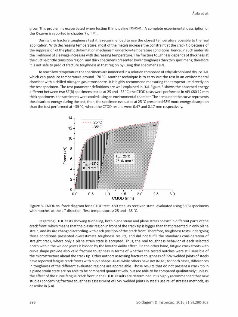
To reach low temperature the specimens are immersed in a solution composed of ethyl alcohol and dry ice [32], which can produce temperature around –70 °C. Another technique is to carry out the test in an environmental chamber with a chilled nitrogen gas atmosphere. It is highly recommend measuring the temperature directly on the test specimen. The test parameter definitions are well explained in [12]. Figure 3 shows the absorbed energy different between two SE(B) specimens tested at 25 and –35 °C, the CTOD tests were performed in API X80 12 mm thick specimens; the specimens were cooled using an environmental chamber. The area under the curve represents the absorbed energy during the test, then, the specimen evaluated at 25 °C presented 68% more energy absorption than the test performed at –35 °C, where the CTOD results were 0.47 and 0.17 mm respectively.
Figure 3. CMOD vs. force diagram for a CTOD test. X80 steel as received state, evaluated using SE(B) specimens with notches at the L-T direction. Test temperatures: 25 and –35 °C.
Regarding CTOD tests showing tunneling, both plane strain and plane stress coexist in different parts of the crack front, which means that the plastic region in front of the crack tip is bigger than that presented in only plane strain, and its size changed according with each position of the crack front. Therefore, toughness tests undergoing those conditions presented overestimate toughness results, and did not fulfill the standards consideration of straight crack, where only a plane strain state is accepted. Thus, the real toughness behavior of each selected notch within the welded joints is hidden by the low-triaxiality effect. On the other hand, fatigue crack fronts with curve shape provide also valid fracture toughness in terms of whether the tested notches were still sensible of the microstructure ahead the crack tip. Other authors assessing fracture toughness of FSW welded joints of steels have reported fatigue crack fronts with curve shape [33,34] while others have not [63,64]; for both cases, differences in toughness of the different evaluated regions are appreciable. Those results that do not present a crack tip in a plane strain state are no able to be compared quantitatively, but are able to be compared qualitatively; unless, the effect of the curve fatigue crack front in the CTOD results are determined. It is highly recommended that new studies concerning fracture toughness assessment of FSW welded joints in steels use relief stresses methods, as describe in [7,8].
Soldagem & Inspeção. 2016;21(3):290-302 297
Guide for Recommended Practices to Perform Crack Tip Opening Displacement Tests in High Strength Low Alloy Steels
2.9. Fracture surface analysis
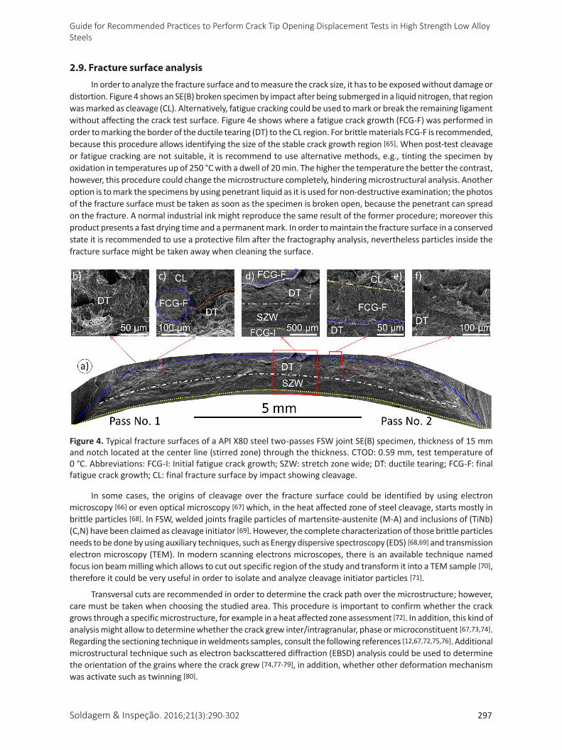
In order to analyze the fracture surface and to measure the crack size, it has to be exposed without damage or distortion. Figure 4 shows an SE(B) broken specimen by impact after being submerged in a liquid nitrogen, that region was marked as cleavage (CL). Alternatively, fatigue cracking could be used to mark or break the remaining ligament without affecting the crack test surface. Figure 4e shows where a fatigue crack growth (FCG-F) was performed in order to marking the border of the ductile tearing (DT) to the CL region. For brittle materials FCG-F is recommended, because this procedure allows identifying the size of the stable crack growth region [65]. When post-test cleavage or fatigue cracking are not suitable, it is recommend to use alternative methods, e.g., tinting the specimen by oxidation in temperatures up of 250 °C with a dwell of 20 min. The higher the temperature the better the contrast, however, this procedure could change the microstructure completely, hindering microstructural analysis. Another option is to mark the specimens by using penetrant liquid as it is used for non-destructive examination; the photos of the fracture surface must be taken as soon as the specimen is broken open, because the penetrant can spread on the fracture. A normal industrial ink might reproduce the same result of the former procedure; moreover this product presents a fast drying time and a permanent mark. In order to maintain the fracture surface in a conserved state it is recommended to use a protective film after the fractography analysis, nevertheless particles inside the fracture surface might be taken away when cleaning the surface.
Figure 4. Typical fracture surfaces of a API X80 steel two-passes FSW joint SE(B) specimen, thickness of 15 mm and notch located at the center line (stirred zone) through the thickness. CTOD: 0.59 mm, test temperature of 0 °C. Abbreviations: FCG-I: Initial fatigue crack growth; SZW: stretch zone wide; DT: ductile tearing; FCG-F: final fatigue crack growth; CL: final fracture surface by impact showing cleavage.
In some cases, the origins of cleavage over the fracture surface could be identified by using electron microscopy [66] or even optical microscopy [67] which, in the heat affected zone of steel cleavage, starts mostly in brittle particles [68]. In FSW, welded joints fragile particles of martensite-austenite (M-A) and inclusions of (TiNb)(C,N) have been claimed as cleavage initiator [69]. However, the complete characterization of those brittle particles needs to be done by using auxiliary techniques, such as Energy dispersive spectroscopy (EDS) [68,69] and transmission electron microscopy (TEM). In modern scanning electrons microscopes, there is an available technique named focus ion beam milling which allows to cut out specific region of the study and transform it into a TEM sample [70], therefore it could be very useful in order to isolate and analyze cleavage initiator particles [71].
Transversal cuts are recommended in order to determine the crack path over the microstructure; however, care must be taken when choosing the studied area. This procedure is important to confirm whether the crack grows through a specific microstructure, for example in a heat affected zone assessment [72]. In addition, this kind of analysismightallowtodeterminewhetherthecrackgrewinter/intragranular,phaseormicroconstituent[67,73,74]. Regarding the sectioning technique in weldments samples, consult the following references [12,67,72,75,76]. Additional microstructural technique such as electron backscattered diffraction (EBSD) analysis could be used to determine the orientation of the grains where the crack grew [74,77-79], in addition, whether other deformation mechanism was activate such as twinning [80].
Ávila et al.
298 Soldagem & Inspeção. 2016;21(3):290-302
2.10. Test report
Before computing the fracture toughness, it is necessary to determine and report the mechanical properties of the material at the required temperatures, such as yield and ultimate stresses, and elastic modulus and Poisson’s ratio. It is recommended to report the direction, sense, depth and location of the notches, specimen geometry, precracking and test parameters, size and shape of the crack, and whether the residual stress were modified. Chemical content and microstructural features might be useful for other readers to compare results.
It is important to carefully avoid using wrong information on materials properties, because this could lead to ignoring the mismatch of properties between the weld joint and base material. Therefore, the fracture toughness could be under - or overestimated [81]; the error could be around ±20% for an arc welded SE(B) specimens of HSLA steel [81-82].
The fracture toughness in the pipeline industry has been assessed the most by using CTOD tests. DNV-OS-F101 [16] is used as a quality control standard for pipeline construction, in which the lower limit value for CTOD is 0.15 mm at the design material temperature. The NORSOK standard M-120 [83] provides CTOD lower limits for several structural steels, where it requires 0.25 mm for the base material and 0.2 mm for the welded condition. API-1104 [84] considers the lower limit to be between 0.13-0.25 mm; in addition, this standard presents a curve relating the imperfection size and applied axial strain to the crack size lower limits of toughness. The Petrobras N-1678 [85] standard requires, for a HSLA steel having 415 MPa and thickness between 38-75 mm, CTOD values between 0.3 mm and 0.25 mm for base and welded metals, respectively.
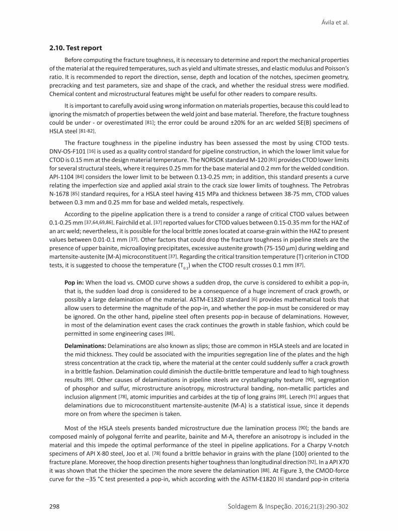
According to the pipeline application there is a trend to consider a range of critical CTOD values between 0.1-0.25 mm [37,64,69,86]. Fairchild et al. [37] reported values for CTOD values between 0.15-0.35 mm for the HAZ of an arc weld; nevertheless, it is possible for the local brittle zones located at coarse-grain within the HAZ to present values between 0.01-0.1 mm [37]. Other factors that could drop the fracture toughness in pipeline steels are the presenceofupperbainite,microalloyingprecipitates,excessiveaustenitegrowth(75-150μm)duringweldingandmartensite-austenite (M-A) microconstituent [37]. Regarding the critical transition temperature (T) criterion in CTOD tests, it is suggested to choose the temperature (T0.1) when the CTOD result crosses 0.1 mm [87].
Pop in: When the load vs. CMOD curve shows a sudden drop, the curve is considered to exhibit a pop-in, that is, the sudden load drop is considered to be a consequence of a huge increment of crack growth, or possibly a large delamination of the material. ASTM-E1820 standard [6] provides mathematical tools that allow users to determine the magnitude of the pop-in, and whether the pop-in must be considered or may be ignored. On the other hand, pipeline steel often presents pop-in because of delaminations. However, in most of the delamination event cases the crack continues the growth in stable fashion, which could be permitted in some engineering cases [88].
Delaminations: Delaminations are also known as slips; those are common in HSLA steels and are located in the mid thickness. They could be associated with the impurities segregation line of the plates and the high stress concentration at the crack tip, where the material at the center could suddenly suffer a crack growth in a brittle fashion. Delamination could diminish the ductile-brittle temperature and lead to high toughness results [89]. Other causes of delaminations in pipeline steels are crystallography texture [90], segregation of phosphor and sulfur, microstructure anisotropy, microstructural banding, non-metallic particles and inclusion alignment [78], atomic impurities and carbides at the tip of long grains [89]. Lerech [91] argues that delaminations due to microconstituent martensite-austenite (M-A) is a statistical issue, since it depends more on from where the specimen is taken.
Most of the HSLA steels presents banded microstructure due the lamination process [90]; the bands are composed mainly of polygonal ferrite and pearlite, bainite and M-A, therefore an anisotropy is included in the material and this impede the optimal performance of the steel in pipeline applications. For a Charpy V-notch specimens of API X-80 steel, Joo et al. [78] found a brittle behavior in grains with the plane {100} oriented to the fracture plane. Moreover, the hoop direction presents higher toughness than longitudinal direction [92]. In a API X70 it was shown that the thicker the specimen the more severe the delamination [88]. At Figure 3, the CMOD-force curve for the –35 °C test presented a pop-in, which according with the ASTM-E1820 [6] standard pop-in criteria
Soldagem & Inspeção. 2016;21(3):290-302 299
Guide for Recommended Practices to Perform Crack Tip Opening Displacement Tests in High Strength Low Alloy Steels
must be considered, then the fracture toughness was computed only with the vertical hatched area. However, the crack growth did not stop there; it maintained a constant growth until it reached an unstable crack growth.
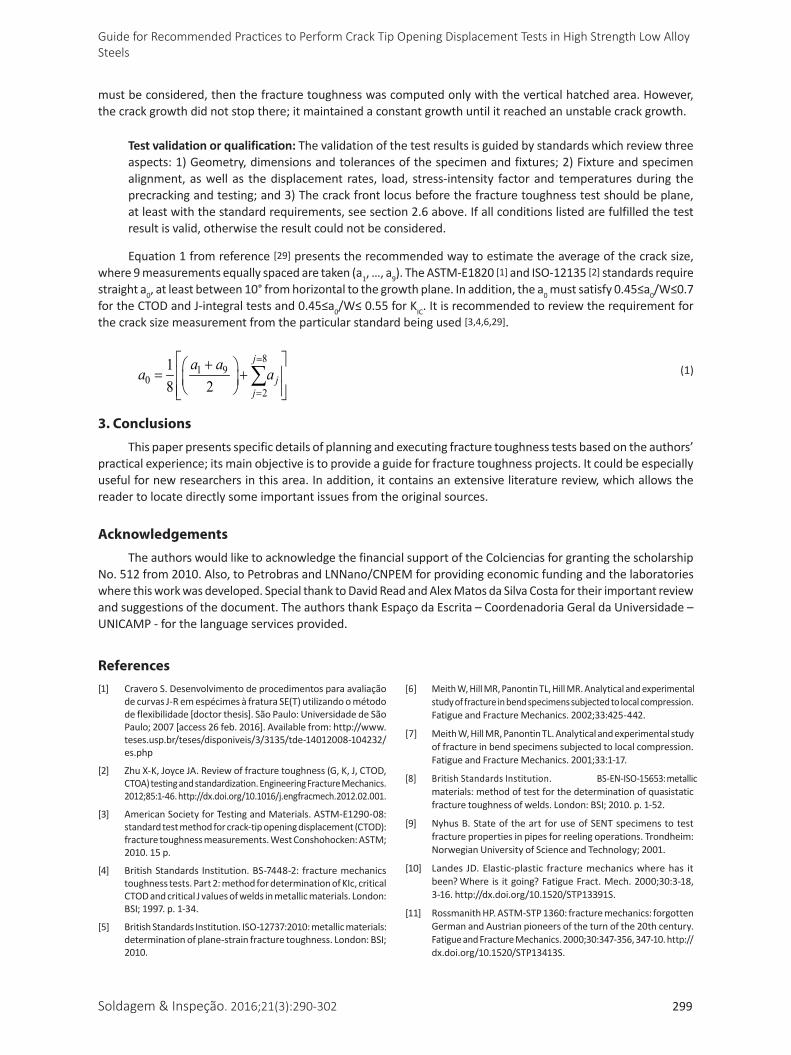
Test validation or qualification: The validation of the test results is guided by standards which review three aspects: 1) Geometry, dimensions and tolerances of the specimen and fixtures; 2) Fixture and specimen alignment, as well as the displacement rates, load, stress-intensity factor and temperatures during the precracking and testing; and 3) The crack front locus before the fracture toughness test should be plane, at least with the standard requirements, see section 2.6 above. If all conditions listed are fulfilled the test result is valid, otherwise the result could not be considered.
Equation 1 from reference [29] presents the recommended way to estimate the average of the crack size, where 9 measurements equally spaced are taken (a1, …, a9). The ASTM-E1820 [1] and ISO-12135 [2] standards require straight a0, at least between 10° from horizontal to the growth plane. In addition, the a0mustsatisfy0.45≤a0/W≤0.7fortheCTODandJ-integraltestsand0.45≤a0/W≤0.55forKIC. It is recommended to review the requirement for the crack size measurement from the particular standard being used [3,4,6,29].
81 9
02
18 2
=
=
+ = +
∑j
jj
a aa a (1)
3. Conclusions
This paper presents specific details of planning and executing fracture toughness tests based on the authors’ practical experience; its main objective is to provide a guide for fracture toughness projects. It could be especially useful for new researchers in this area. In addition, it contains an extensive literature review, which allows the reader to locate directly some important issues from the original sources.
Acknowledgements
The authors would like to acknowledge the financial support of the Colciencias for granting the scholarship No.512from2010.Also,toPetrobrasandLNNano/CNPEMforprovidingeconomicfundingandthelaboratorieswhere this work was developed. Special thank to David Read and Alex Matos da Silva Costa for their important review and suggestions of the document. The authors thank Espaço da Escrita – Coordenadoria Geral da Universidade – UNICAMP - for the language services provided.
References[1] Cravero S. Desenvolvimento de procedimentos para avaliação
de curvas J-R em espécimes à fratura SE(T) utilizando o método de flexibilidade [doctor thesis]. São Paulo: Universidade de São Paulo;2007[access26feb.2016].Availablefrom:http://www.teses.usp.br/teses/disponiveis/3/3135/tde-14012008-104232/es.php
[2] Zhu X-K, Joyce JA. Review of fracture toughness (G, K, J, CTOD, CTOA) testing and standardization. Engineering Fracture Mechanics. 2012;85:1-46. http://dx.doi.org/10.1016/j.engfracmech.2012.02.001.
[3] American Society for Testing and Materials. ASTM-E1290-08: standard test method for crack-tip opening displacement (CTOD): fracture toughness measurements. West Conshohocken: ASTM; 2010. 15 p.
[4] British Standards Institution. BS-7448-2: fracture mechanics toughness tests. Part 2: method for determination of KIc, critical CTOD and critical J values of welds in metallic materials. London: BSI; 1997. p. 1-34.
[5] British Standards Institution. ISO-12737:2010: metallic materials: determination of plane-strain fracture toughness. London: BSI; 2010.
[6] Meith W, Hill MR, Panontin TL, Hill MR. Analytical and experimental study of fracture in bend specimens subjected to local compression. Fatigue and Fracture Mechanics. 2002;33:425-442.
[7] Meith W, Hill MR, Panontin TL. Analytical and experimental study of fracture in bend specimens subjected to local compression. Fatigue and Fracture Mechanics. 2001;33:1-17.
[8] British Standards Institution. BS-EN-ISO-15653: metallic materials: method of test for the determination of quasistatic fracture toughness of welds. London: BSI; 2010. p. 1-52.
[9] Nyhus B. State of the art for use of SENT specimens to test fracture properties in pipes for reeling operations. Trondheim: Norwegian University of Science and Technology; 2001.
[10] Landes JD. Elastic-plastic fracture mechanics where has it been? Where is itgoing?FatigueFract.Mech.2000;30:3-18,3-16. http://dx.doi.org/10.1520/STP13391S.
[11] Rossmanith HP. ASTM-STP 1360: fracture mechanics: forgotten German and Austrian pioneers of the turn of the 20th century. Fatigue and Fracture Mechanics. 2000;30:347-356, 347-10. http://dx.doi.org/10.1520/STP13413S.
Ávila et al.
300 Soldagem & Inspeção. 2016;21(3):290-302
[12] Anderson TL. Fracture mechanics: fundamentals and applications. 3rd ed. Boca Raton: CRC Press; 2005.
[13] Hertzberg RW, Vinci RP, Hertzberg JL. Deformation and fracture mechanics of engineering materials. 5th ed. Hoboken: Wiley; 2013.
[14] Dowling NE. Mechanical behavior of materials. 4th ed. Upper Saddle River: Prentice Hall; 2013.
[15] Harrison JD, Anderson TL. Developments in the application of the CTOD approach to fracture assessment of welded construction. In: 18th Symposium Fracture Mechanics: ASTM-STP 945; 1985 June 25-27; Boulder, USA. West Conshohocken: ASTM; 1988. p. 468-484.
[16] DNV GL. DNV-OS-F101: submarine pipeline systems. Oslo: DNV GL; 2012. p. 1-367.
[17] Petrobras. N-1859: qualificação de consumíveis de soldagem. Rio de Janeiro: CONTEC Petrobras; 2012. p. 1-27.
[18] British Standards Institution. BS-7910: guide to methods for assessing the acceptability of flaws in metallic structures. London: BSI; 2005. 306 p.
[19] Koo JM, Park S, Seok C. Evaluation of fracture toughness of nuclear piping using real pipe and tensile compact pipe specimens. Nuclear Engineering and Design. 2013;259:198-204. http://dx.doi.org/10.1016/j.nucengdes.2013.03.001.
[20] Rodriguez C, Belzunce FJ, Garcia TE, Peñuelas I. Constraint dependence of the fracture toughness of reduced activation ferritic–martensitic Eurofer steel plates. Engineering Fracture Mechanics. 2013;103:60-68. http://dx.doi.org/10.1016/j.engfracmech.2012.05.003.
[21] Tyson WR, Shen G, Gianetto JA, Park DY. Development of a low-constraint SE(T) Toughness Test. Key Engineering Materials. 2011;488-489:126-129.http://dx.doi.org/10.4028/www.scientific.net/KEM.488-489.126.
[22] British Standards Institution. BS-8571: method of test for determination of fracture toughness in metallic materials using single edge notched tension (SENT) specimens. London: BSI; 2014. 28 p.
[23] DNV GL. DNV-RP-F108: fracture control for pipeline installation methods introducing cyclic plastic strain. London: BSI; 2006. p. 1-24.
[24] Exxonmobil. Measurement of Crack-Tip Opening Displacement (CTOD) fracture resistance curves using Single-Edge Notched Tension (SENT) specimens. Irving; 2010. p. 1-36.
[25] Castelluccio GM, Perez JEI, Yawny AA, Ernst HA. Fracture testing of the heat affected zone from welded steel pipes using an in situ stage. Engineering Fracture Mechanics. 2013;98:52-63. http://dx.doi.org/10.1016/j.engfracmech.2012.11.010.
[26] Chan KS. In-Situ SEM J-testing and crack-tip micromechanics of Zircaloy-4 by three-point bending. Experimental Mechanics. 2011;52(9):1251-1265.http://dx.doi.org/10.1007/s11340-011-9587-8.
[27] Qian X, Li Y, Ou Z. Ductile tearing assessment of high-strength steel X-joints under in-plane bending. Engineering Failure Analysis. 2013;28:176-191. http://dx.doi.org/10.1016/j.engfailanal.2012.10.017.
[28] American Society for Testing and Materials. ASTM-E399-09: standard test method for linear-elastic plane-strain fracture toughness KIc of metallic materials. West Conshohocken: ASTM; 2010. 33 p.
[29] British Standards Institution. ISO-12135: metallic materials: unified method of test for the determination of quasistatic fracture toughness. London: BSI; 2002. 100 p.
[30] Silva MC. Avaliação da tenacidade à fratura de soldas de alta resistência e baixa liga pelo método da integral-J [dissertação de mestrado]. São Paulo: Universidade de São Paulo; 1998 [access26feb2016].Availablefrom:http://www.teses.usp.br/teses/disponiveis/88/88131/tde-19042002-142153/pt-br.php
[31] Palmer AC, King RA. Subsea pipeline engineering. 2nd ed. Tulsa: PennWell Publishing; 2008.
[32] Silva MC. Determinação experimental da tenacidade à fratura da zona termicamente afetada de junta soldada de aço API 5L X80 [doctor thesis]. São Paulo: Universidade de São Paulo; 2009 [access26feb.2016].Availablefrom:http://www.teses.usp.br/teses/disponiveis/3/3135/tde-11082010-160030/pt-br.php
[33] Tribe A. Study on the fracture toughness of friction stir welded API X80 [master’s dissertation]. Provo: Brigham Young University;2012[access26feb.2016].Availablefrom:http://scholarsarchive.byu.edu/etd/3740
[34] Horschel JD. Mode I fracture toughness testing of friction stir processed HSLA-65 [master’s dissertation]. Provo: Brigham Young University; 2008 [access 26 feb. 2016]. Available from: http://scholarsarchive.byu.edu/etd/149
[35] Jang J, Lee J-S, Ju J-B, Lee B-W, Kwon D, Kim W-S. Determination of microstructural criterion for cryogenic toughness variation in actual HAZs using microstructure-distribution maps. Materials Science and Engineering A. 2003;351(1-2):183-189. http://dx.doi.org/10.1016/S0921-5093(02)00850-X.
[36] Bayley C, Aucoin N. Fracture testing of welded single edge notch tensile specimens. Engineering Fracture Mechanics. 2013;102:257-270. http://dx.doi.org/10.1016/j.engfracmech.2013.02.020.
[37] Fairchild DP, Bangaru NV, Koo JY, Harrison PL, Ozekcin A. A study concerning intercritical HAZ microstructure and toughness in HSLA steels. Welding Journal. 1991;(Suppl):321s-330s.
[38] Chludzinski M, Paes MTP, Bastian FL, Strohaecker TR. Fracture toughness of friction hydro-pillar processing welding in C-Mn steel. Materials & Design. 2012;33:340-344. http://dx.doi.org/10.1016/j.matdes.2011.07.056.
[39] Rodriguez JF, Fonseca EB, Ramirez AJ. Estudo de soldabilidade do aço inoxidável duplex 2507 e do aço 9Ni. Campinas; 2015.
[40] Verstraete MA, Hertelé S, Denys RM, Van Minnebruggen K, Waele W. Evaluation and interpretation of ductile crack extension in SENT specimens using unloading compliance technique. Engineering Fracture Mechanics. 2014;115:190-203. http://dx.doi.org/10.1016/j.engfracmech.2013.11.004.
[41] Fairchild DP, Macia ML, Wang X, Kibey S, Krishnan VR, Bardi H, et al. A multi-tiered procedure for engineering critical assessment of strain-based pipelines. Hawaii: International Society of Offshore and Polar Engineers; 2011. p. 698-705.
[42] Verstraete MA, Denys RM, Van Minnebruggen K, Hertelé S, Waele W. Determination of CTOD resistance curves in side-grooved single-edge notched tensile specimens using full field deformation measurements. Engineering Fracture Mechanics. 2013;110:12-22. http://dx.doi.org/10.1016/j.engfracmech.2013.07.015.
[43] Zhenkun L, Ruixiang B, Libo D, Wei Q. Noncontact optical measurement of CTOA and CTOD for interface crack in DCB test. Optics and Lasers in Engineering. 2012;50(7):964-970. http://dx.doi.org/10.1016/j.optlaseng.2012.01.026.
[44] Fagerholt E, Østby E, Børvik T, Hopperstad OS. Investigation of fracture in small-scale SENT tests of a welded X80 pipeline steel using Digital image correlation with node splitting. Engineering Fracture Mechanics. 2012;96:276-293. http://dx.doi.org/10.1016/j.engfracmech.2012.08.007.
Soldagem & Inspeção. 2016;21(3):290-302 301
Guide for Recommended Practices to Perform Crack Tip Opening Displacement Tests in High Strength Low Alloy Steels
[45] Gubeljak N, Chapetti MD, Predan J, Landes JD. CTOD-R curve construction from surface displacement measurements. Engineering Fracture Mechanics. 2011;78(11):2286-2297. http://dx.doi.org/10.1016/j.engfracmech.2011.05.002.
[46] Philippa LM, Henryk GP. Validation of methods to determine CTOD from SENT specimens. Hawaii: International Society of Offshore and Polar Engineers; 2012. p. 1-8.
[47] Lucon E. Effect of Electrical Discharge Machining (EDM) on charpy test results from miniaturized steel specimens. Journal of Testing and Evaluation. 2012;41:1-9.
[48] American Society for Testing and Materials. ASTM-E647-13e1: standard test method for measurement of fatigue crack growth rates. West Conshohocken: ASTM; 2013.
[49] British Standards Institution. BS-7448-1: fracture mechanics toughness tests. Part 1: method for determination of KIc, critical CTOD and critical J values of metallic materials. London: BSI; 1991. p. 1-48.
[50] Scibetta M, Lucon E, Walle EVAN, Valo M. Towards a uniform precracking procedure for fracture toughness testing. International Journal of Fracture. 2002;117(3):287-296. http://dx.doi.org/10.1023/A:1022072320277.
[51] Steuwer A, Barnes SJ, Altenkirch J, Johnson R, Withers PJ. Friction stir welding of HSLA-65 steel. Part II: the influence of weld speed and tool material on the residual stress distribution and tool wear. Metallurgical and Materials Transactions. A, Physical Metallurgy and Materials Science. 2012;43A(7):2356-2365. http://dx.doi.org/10.1007/s11661-011-0643-x.
[52] Lee Y, Kim J-Y, Lee J-S, Kim K-H, Koo JY, Kwon D. Using the instrumented indentation technique for stress characterization of friction stir-welded API X80 steel. Philosophical Magazine. 2006;86(33-35):5497-5504. http://dx.doi.org/10.1080/14786430600776330.
[53] Farahani M, Sattari-Far I. Effects of residual stresses on crack-tip constraints. Sci. Iran. 2011;18(6):1267-1276. http://dx.doi.org/10.1016/j.scient.2011.11.024.
[54] Pereira MM, Wohlfahrt H, Darwish F. A simplified method for evaluation residual stresses by means of CTOD measurements. In: 11th European Conference on Fracture – ECF; 1996 September 3-6; Poitiers-Futuroscope, France. West Midlands: Engineering Materials Advisory Services; 1996. p. 2193-2198.
[55] Bastian FL, Santos MA. Efeito de entalhes laterais nos corpos de prova nos valores de abertura de trinca CTOD em aços para tubos. In: 46° Congresso anual da ABM; 1991 September 15-19; São Paulo, Brazil. São Paulo: ABM; 1991. p. 479-493.
[56] Bayão TRV. Estudo comparativo dos aços microligados API-5L-X60 e API-5L-X70, usados para confecção de tubos, quanto à tenacidade à fratura [dissertação de mestrado]. Ouro Preto: Universidade Federal de Ouro Preto; 2008 [access 26 feb. 2016]. Available from:http://www.repositorio.ufop.br/handle/123456789/2817
[57] Mahmoudi AH, Hadidi-Moud S, Truman CE, Smith DJ. Influence of residual stress on the fracture behaviour of an Aluminium alloy. In: International Conference on Advances in Mechanical Engineering 2003 May 13-15; Iran. New Delhi: ISME; 2003. vol. 5, p. 348-355.
[58] Baek J, Kim Y, Kim C, Kim W, Seok C. Effects of pre-strain on the mechanical properties of API 5L X65 pipe. Materials Science and Engineering A. 2010;527(6):1473-1479. http://dx.doi.org/10.1016/j.msea.2009.10.017.
[59] Ávila JAD, Ruchert COFT, Mei PR, Reppold RM, Piza MTP, Ramirez AJ. Fracture toughness assessment at different temperatures and regions within a friction stirred API 5L X80 steel welded plates. Engineering Fracture Mechanics. 2015;147:176-186. http://dx.doi.org/10.1016/j.engfracmech.2015.08.006.
[60] Silva MC. Caracterização das propriedades mecânicas e metalúrgicas do aço API 5L X 80 e determinação experimental de curvas J-R para avaliação da tenacidade a fratura [dissertação de mestrado]. São Paulo: Universidade de São Paulo; 2004 [access26feb2016].Availablefrom:http://www.teses.usp.br/teses/disponiveis/3/3135/tde-11022005-162828/pt-br.php
[61] Valim MT. Fracture toughness of the welded joint gotten the submerged arc of steel API 5L Grade X80. Rio de Janeiro: Pontifícia Universidade Católica do Rio de Janeiro; 2005 [access 26 feb. 2016].Available from:http://www.maxwell.vrac.puc-rio.br/Busca_etds.php?strSecao=resultado&nrSeq=8193@2
[62] Anderson TL, McHenry HI, Dawes MG. Elastic-plastic fracture toughness test with single-edge notched bend specimens. West Conshohocken: ASTM; 1970. 40 p.
[63] Santos TF, Hermenegildo TF, Afonso CRM, Marinho RR, Paes MTP, Ramirez AJ. Fracture toughness of ISO 3183 X80M (API 5L X80) steel friction stir welds. Engineering Fracture Mechanics. 2010;77(15):2937-2945. http://dx.doi.org/10.1016/j.engfracmech.2010.07.022.
[64] Kumar A, Fairchild DP, Anderson TD, Jin HW, Ayer R, Macia ML, et al. Research progress on friction stir welding of pipeline steels. In: International Pipeline Conference & Exposition; 2010 September 27-October 1; Calgary, Canada. New York: ASME; 2010. p. 1-8.
[65] Landes JD. Evaluation of the ISO J initiation procedure using the EURO fracture toughness data set. International Journal of Fracture. 2007;145(4):285-297. http://dx.doi.org/10.1007/s10704-007-9118-x.
[66] Davis CL, King JE. Cleavage initiation in the intercritically reheated coarse-grained heat-affected zone: part I: fractographic evidence. Metallurgical and Materials Transactions A, Physical Metallurgy and Materials Science. 1994;25A(3):563-573. http://dx.doi.org/10.1007/BF02651598.
[67] Harrison PL, Abson DJ, Jones AR, Sparkers DJ. Fractographic and metallographic study of the initiation of brittle fracture in weldments. ASTM Special Technical Publication. 1990;1085:102-122.
[68] Fairchild DP, Howden DG, Clark WAT. The mechanism of brittle fracture in a microalloyed steel. Part I: inclusion-induced cleavage. Metallurgical and Materials Transactions A, Physical Metallurgy and Materials Science. 2000;31(3):641-652. http://dx.doi.org/10.1007/s11661-000-0007-4.
[69] Fairchild DP, Wasson AJ, Kumar A, Macia ML, Anderson TD. Fractographic investigation of cleavage initiation in steel friction stir welds. In: 9th International Conference on Trends in Welding Research; 2012 June 4-8; Chicago, USA. Geauga County: ASM International; 2012. p. 193-200.
[70] Cairney JM, Munroe PR, Schneibel JH. Examination of fracture surfaces using focused ion beam milling. Scripta Materialia. 2000;42(5):473-478. http://dx.doi.org/10.1016/S1359-6462(99)00374-7.
[71] Mohseni P. Brittle and ductile fracture of X80 arctic steel [doctor thesis]. Trondheim: Norwegian University of Science and Technology; 2012 [access 26 feb. 2016]. Available from: http://www.diva-portal.org/smash/record.jsf?pid=diva2%3A567896&dswid=-663
[72] Burget W, Blauel JG. Fracture toughness of manual metal-arc and submerged-arc welded joints in normalized carbon-manganese steels. ASTM Special Technical Publication. 1990;1058:272-299.
[73] Shin SY, Woo KJ, Hwang B, Kim S, Lee S. Fracture-toughness analysis in transition-temperature region of Three American Petroleum Institute X70 and X80 pipeline steels. Metallurgical
Ávila et al.
302 Soldagem & Inspeção. 2016;21(3):290-302
and Materials Transactions A, Physical Metallurgy and Materials Science. 2009;40(4):867-876. http://dx.doi.org/10.1007/s11661-008-9764-2.
[74] Shin SY, Han SY, Hwang B, Lee CG, Lee S. Effects of Cu and B addition on microstructure and mechanical properties of high-strength bainitic steels. Materials Science and Engineering A. 2009;517(1-2):212-218. http://dx.doi.org/10.1016/j.msea.2009.03.052.
[75] Machida S, Miyata T, Toyosada M, Yukito H. Study of methods for CTOD testing of weldments. In: Potter JM, McHenry HI. Fatigue and fracture testing of weldments. West Conshohocken: ASTM; 1990:142-156.
[76] Fairchild DP. Fracture toughness testing of weld heat-affected zones in structural steel. ASTM Special Technical Publication. 1990;1058:117-141.
[77] Mohseni P, Solberg JK, Karlsen M, Akselsen OM, Ostby E. Application of combined EBSD and 3D-SEM technique on crystallographic facet analysis of steel at low temperature. Journal of Microscopy. 2013;251(1):45-56. http://dx.doi.org/10.1111/jmi.12041. PMid:23692572.
[78] Joo MS, Suh D-W, Bae J, Bhadeshia HKDH. Role of delamination and crystallography on anisotropy of Charpy toughness in API-X80 steel. Materials Science and Engineering A. 2012;546:314-322. http://dx.doi.org/10.1016/j.msea.2012.03.079.
[79] Han SY, Shin SY, Lee S, Kim NJ, Bae J, Kim K. Effects of cooling conditions on tensile and charpy impact properties of API X80 linepipe steels. Metallurgical and Materials Transactions. A, Physical Metallurgy and Materials Science. 2010;41A:239-251. http://dx.doi.org/10.1007/s11661-009-0135-4.
[80] Gludovatz B, Hohenwarter A, Catoor D, Chang E, George EP, Ritchie RO. A fracture-resistant high-entropy alloy for cryogenic applications.Science.2010;345(80):1153-1158.http://dx.doi.org/10.1126/science.1254581. PMid:25190791.
[81] Ruggieri C. An engineering methodology to assess effects of weld strength mismatch on cleavage fracture toughness using the Weibull stress approach. International Journal of Fracture. 2010;164(2):231-252. http://dx.doi.org/10.1007/s10704-010-9488-3.
[82] Donato GHB, Magnabosco R, Ruggieri C. Effects of weld strength mismatch on J and CTOD estimation procedure for SE(B)
specimens. International Journal of Fracture. 2009;159(1):1-20. http://dx.doi.org/10.1007/s10704-009-9377-9.
[83] NORSOK Standards. M-120: material data sheets for structural steel. Lysaker: NORSOK Standards; 2008.
[84] American Petroleum Institute. API-1104: welding of pipelines and related facilities. Washington: API; 2005.
[85] Petrobras. N-1678: estruturas oceânicas: aço. Rio de Janeiro: CONTEC Petrobras; 2010. 50 p.
[86] Fairchild DP, Kumar A, Ford SJ, Nissley N, Ayer R, Jin HW, et al. Research concerning the friction stir welding of linepipe steels. In: 8th International Trends in Welding Research Conference; 2008 June 1-6; Georgia, USA. Ohio: ASM International; 2009. p.371-380.http://dx.doi.org/10.1361/cp2008twr371.
[87] Laitinen R. Improvement of weld haz toughness at low heat input by controlling the distribution of M-A constituents [doctor thesis]. Oulu: University of Oulu; 2006 [access 26 feb. 2016]. Availablefrom:http://urn.fi/urn:isbn:9514280016
[88] Guo W, Dong H, Lu M, Zhao X. The coupled effects of thickness and delamination on cracking resistance of X70 pipeline steel. International Journal of Pressure Vessels and Piping. 2002;79(6):403-412. http://dx.doi.org/10.1016/S0308-0161(02)00039-X.
[89] Punch R, Strangwood M, Davis C. Origin and propagation of splits in high-strength low-alloy strip steel. Metallurgical and Materials Transactions A, Physical Metallurgy and Materials Science. 2012;43(12):4622-4632. http://dx.doi.org/10.1007/s11661-012-1307-1.
[90] Joo MS, Suh D-W, Bae J, Mouriño NS, Petrov R, Kestens LAI, et al. Experiments to separate the effect of texture on anisotropy of pipeline steel. Materials Science and Engineering A. 2012;556:601-606. http://dx.doi.org/10.1016/j.msea.2012.07.033.
[91] Lerech S. Relação entre a energia Charpy e a ductilidade através da espessura de aço API 5L X80. Rio de Janeiro: PUC; 2011 [access26feb.2016].Availablefrom:http://www.puc-rio.br/Pibic/relatorio_resumo2011/Relatorios/CTC/DEMA/DEMA-Sohad%20Lerech.pdf
[92] Ju J, Lee J, Jang J. Fracture toughness anisotropy in a API steel line-pipe. Materials Letters. 2007;61(29):5178-5180. http://dx.doi.org/10.1016/j.matlet.2007.04.007.
Recommended


![Fatigue Crack Growth Under Constant and Variable Amplitude ... · crack closure effects, crack tip blunting, strain hardening and residual stresses at the crack tip [8]. In this paper,](https://img.pdfslide.us/doc/110x75/5e57a3e927dba642fd37d97c/fatigue-crack-growth-under-constant-and-variable-amplitude-crack-closure-effects.jpg)