MASAAG Paper 120
MASAAG Paper 120
Guidance on Helicopter Operational Data
Recording Programmes
Prof S C Reed, Mr G K Terry, Mr B H E Perrett
27 October 2017

ii MASAAG Paper 120
DISTRIBUTION
Task Sponsor
Military Aviation Authority - Certification (Structures 3 – Helicopters)
MASAAG Members
Military Aviation Authority – Certification (Structures & Aircraft Design Standards)
Military Aviation Authority – Certification (Structures 1 – Large Aircraft)
Military Aviation Authority – Certification (Structures 2 – Fast Jets & Unmanned Aerial Vehicles)
Military Aviation Authority – Certification (Structures 3 – Helicopters)
Military Aviation Authority – Certification (Structures 4 – Gen)
Military Aviation Authority – Certification (ADS – DS970)
DES DAT- Aircraft Eng Mgr
Prof S Reed, Dstl
Dr M Mishon, 1710 NAS
Mr T Cook, Airbus UK
Mr M Collins, Airbus UK
Mr M Overd, Leonardo Helicopters
Mr K Fisher, BAE Systems
Mr D Patterson, Bombardier Aerospace
Mr S Dosman, Marshall Aerospace
Mr TBN, Marshall Aerospace
Mrs A Mew, QinetiQ Military Aviation Authority – Certification (Structures 4a - Gen)
Authorship Panel
Mr Sean Perkins, Aviation Requirements
Mr Tim Shucksmith, 1710 NAS
Mr Jeff Day, 1710 NAS
Mr Mike Overd, Leonardo Helicopters
Mr Mike Rees, Leonardo Helicopters
Lt Cdr Mark Hepplewhite, DES Lynx-Wildcat EDA WildcatMech
Mr Mick George, DES P2G PumaEngProjMgr

MASAAG Paper 120 iii
EXECUTIVE SUMMARY
An Operational Data Recording (ODR) programme is identified in Ministry of Defence (MOD)
Regulatory Article 5720(4) – Validating Structural Integrity - as the means by which Operational
Loads and Usage Validation of MOD helicopter fleets should be carried out. Currently there is
little guidance material (GM) available on how to undertake such a programme.
ODR is one of a range of programmes undertaken to provide Structural Integrity (SI) assurance.
The aim of ODR is to validate the in-service operational usage, in terms of frequency of
occurrence of fatigue-significant events and their associated severity, using representative flight
data, for comparison against the design assumptions and substantiation.
The aim of this paper is to provide guidance on the conduct of an ODR programme. MASAAG
Paper 109 – Guidance for Operational Loads Measurement Programmes, the fixed-wing
equivalent of ODR, contains useful information on instrumentation, data acquisition and analysis,
equally applicable to helicopters and hence, to avoid unnecessary repetition, the focus of this
paper is on defining the ODR requirement and identifying the helicopter-specific issues
associated with usage validation programmes.
The contribution of the Authorship Panel members, who have provided input and comment
during the development and review of this paper, is gratefully acknowledged.
Paper 120 was accepted by the MASAAG membership at the 83rd MASAAG meeting on 26
October 2017.

iv MASAAG Paper 120
AUTHORSHIP
Principal Authors:
Prof Steve Reed, Technical Fellow Structural Integrity and Ageing Aircraft, Dstl
Mr Glenn Terry, RAE (Structures)
Mr Brian Perrett, Helisac Ltd
Authorship Panel:
Mr Sean Perkins, Aviation Requirements
Mr Tim Shucksmith, 1710 NAS
Mr Jeff Day, 1710 NAS
Mr Mike Overd, Leonardo Helicopters
Mr Mike Rees, Leonardo Helicopters
Lt Cdr Mark Hepplewhite DES Lynx-Wildcat EDA WildcatMech
DES P2G PumaEngProjMgr

MASAAG Paper 120 v
TABLE OF CONTENTS
DISTRIBUTION .................................................................................................................................. II
EXECUTIVE SUMMARY ..................................................................................................................... III
AUTHORSHIP ................................................................................................................................... IV
TABLE OF CONTENTS ........................................................................................................................ V
ABBREVIATIONS ............................................................................................................................... IX
1 INTRODUCTION ................................................................................................................. 11
2 ODR DEFINITION ................................................................................................................ 13
3 ORIGINS AND REGULATIONS .......................................................................................... 14
3.1 Origins .................................................................................................................... 14
3.2 Military Regulatory and Guidance Material ............................................................ 14
3.3 Civil Regulations ..................................................................................................... 14
4 ORGANISATION AND TIMING .......................................................................................... 16
4.1 Organisation ........................................................................................................... 16
4.2 Timing ..................................................................................................................... 16
5 AIMS AND REQUIREMENTS DEFINITION........................................................................ 18
5.1 Aims ........................................................................................................................ 18
5.2 Requirements Definition Study ............................................................................... 19
5.3 Primary Aim – Validate In-Service Usage Against Design Assumptions and
Substantiation .......................................................................................................................... 19
5.3.1 Fatigue Substantiation Process .............................................................................. 19
5.3.2 Identification of Validation Method and Data Capture ............................................ 20

vi MASAAG Paper 120
5.3.3 Identification of Short Life or Usage-Sensitive Critical structural features .............. 21
5.3.4 Identification of Shortfalls in Loads Validation ........................................................ 22
5.4 Secondary Aims ...................................................................................................... 22
5.4.1 Validate Fatigue Spectra, Lives or Inspection Periodicity ....................................... 22
5.4.2 Measure or Validate Component Loads or Strains ................................................. 23
5.4.3 Identify or Measure Damaging Events, Conditions or Manoeuvres ........................ 23
5.4.4 Provision of Data to Support Investigations of Life Extension ................................ 23
5.4.5 Provision of Non-Structural Information .................................................................. 23
5.5 Requirements and Approach .................................................................................. 23
5.5.1 Generate Requirements .......................................................................................... 23
5.5.2 Existing Data Sources and Additional Data Capture Requirements ....................... 24
5.5.3 Requirements Definition Study Report .................................................................... 25
5.6 ODR Category ......................................................................................................... 25
6 DATA SOURCES ................................................................................................................. 27
6.1 Existing Data Sources ............................................................................................. 27
6.1.1 Flight Records ......................................................................................................... 27
6.1.2 Existing Electronic Flight Data Systems (HUMS/FDR) ........................................... 27
6.2 Additional Data Sources – Category 2 Programmes .............................................. 28
6.3 Data Sources – Category 3 Programmes ............................................................... 30
7 INSTALLATION ................................................................................................................... 31
7.1 Modification Approach ............................................................................................. 31
7.2 Calibration ............................................................................................................... 32
7.3 Confidence Checks ................................................................................................. 33
7.4 Flight Test Requirements ........................................................................................ 33

MASAAG Paper 120 vii
8 PROGRAMME MANAGEMENT ......................................................................................... 34
8.1 Data Capture Requirements ................................................................................... 34
8.2 Data Management Plan .......................................................................................... 35
8.3 In-service Maintenance and Through-Life Support ................................................ 35
8.3.1 ODR System Maintenance ..................................................................................... 35
8.3.2 Effect on Aircraft Maintenance ............................................................................... 35
8.3.3 ODR Support Policy, Spares, Support and Test Equipment .................................. 36
8.3.4 Repeat Calibration Plan .......................................................................................... 36
8.3.5 Obsolescence Reviews .......................................................................................... 36
8.4 Operating Unit Involvement .................................................................................... 37
9 DATA ANALYSIS ................................................................................................................ 39
9.1 Data Analysis Process Design ............................................................................... 39
9.2 Maximise Use of Existing Analysis Tools ............................................................... 40
9.3 Data Anomaly Detection ......................................................................................... 40
9.4 Flight Condition Recognition Algorithms ................................................................ 41
9.5 Analysis Tool Validation ......................................................................................... 42
10 REPORTING .......................................................................................................... 43
10.1 Post Installation and Flight Test Report ................................................................. 43
10.2 Progress Reporting Against Programme Requirements ........................................ 43
10.3 Interim Reporting Against Programme Requirements............................................ 44
10.4 Final Reporting ....................................................................................................... 45
10.5 Follow-up Actions ................................................................................................... 46
11 RECOMMENDATIONS .......................................................................................... 47

viii MASAAG Paper 120
12 REFERENCES ........................................................................................................ 48
APPENDIX A: GENERIC STATEMENT OF REQUIREMENT FOR ODR..................................................... 50
APPENDIX B: GLOSSARY OF TERMS ................................................................................................ 55
APPENDIX C: EXAMPLE DESIGN USAGE SPECTRA ........................................................................... 57
APPENDIX D: EXAMPLE SCRIPTED FLIGHT SCHEDULE FOR FCR VALIDATION .................................... 61

MASAAG Paper 120 ix
ABBREVIATIONS
ADD Analysis Definition Document AGARD Advisory Group for Aerospace Research and Development AGL Above Ground Level AMC Acceptable Means of Compliance AOB Angle of Bank BCAR British Civil Airworthiness Requirements CG Centre of Gravity CS Certification Specification .csv Comma Separated Variables DAU Data Acquisition Unit DEF STAN Defence Standard DO Design Organisation DT Delivery Team DUS Design Usage Spectrum EASA European Aviation Safety Agency FAA Federal Aviation Administration FC Flight Condition FCR Flight Condition Recognition FDR Flight Data Recorder FLS Flight Load Survey FTI Flight Test Instrumentation FTR Fatigue Type Record GAG Ground Air Ground GM Guidance Material HIGE Hover In Ground Effect HOGE Hover Out of Ground Effect HUMS Health and Usage Monitoring System IAS Indicated Air Speed ISAA Independent Structural Airworthiness Advisor MAA Military Aviation Authority MASAAG Military Aircraft Structural Airworthiness Advisory Group MDRE Manual Data Recording Exercise Mil Std US Military Standard MOD Ministry of Defence (UK) NAS Naval Air Squadron ODR Operational Data Recording (Rotary Wing) OEM Original Equipment Manufacturer OLM Operational Loads Measurement OSD Out of Service Date PT Project Team RA Regulatory Article RF Radio Frequency SI Structural Integrity SIWG Structural Integrity Working Group SOI Statement of Operating Intent SOIU Statement of Operating Intent and Usage SOO Special Order Only SOR Statement of Requirement SPC Sortie Profile Code TAA Type Airworthiness Authority UK United Kingdom US United States

x MASAAG Paper 120
Intentionally Blank

MASAAG Paper 120 11
1 INTRODUCTION
An Operational Data Recording (ODR) programme is identified in Ministry of Defence (MOD)
Regulatory Article 5720(4) – Validating Structural Integrity - as the means by which Operational
Loads and Usage Validation of MOD helicopter fleets should be carried out. Currently there is
little guidance material (GM) available on how to undertake such a programme.
ODR is one of a range of programmes undertaken to provide Structural Integrity (SI) assurance.
The aim of ODR is to validate the in-service operational usage, in terms of frequency of
occurrence of fatigue-significant events and their associated severity, using representative flight
data, for comparison against the design assumptions and substantiation.
The aim of this paper is to provide guidance on the conduct of an ODR programme. MASAAG
Paper 109 – Guidance for Operational Loads Measurement Programmes [2] - the fixed-wing
equivalent of ODR, contains useful information on instrumentation, data acquisition and analysis,
equally applicable to helicopters and hence, to avoid unnecessary repetition, the focus of this
paper is on defining the ODR requirement and the helicopter-specific issues associated with
usage validation programmes.
Within each of the sections in this paper, the work needed to undertake ODR is identified as
ODR Actions - with additional explanation where necessary. The ODR Actions have been
collated into a generic statement of requirement (SOR) and this has been reproduced in
Appendix A.
Defining the detailed requirements for ODR is one of the key aspects of the programme and
may well vary significantly between platforms. The detailed requirements for each ODR
programme will depend upon the design and substantiation approach for the platform, the SI
history and the existing depth, understanding and validation of the usage and loads. The
Design Organisation (DO) has the understanding of the aircraft design, substantiation and broad
service usage history (including MOD) necessary to identify where further validation of in-
service usage may be required necessary. Therefore, the ODR programme needs to be
undertaken either by the DO or in close cooperation with the DO.
Language:
This paper has been written as guidance material (GM) in support of the Structural Integrity
Validation sections of RA 5720. Therefore, language appropriate to RA has been used where
possible; the term ‘shall’ has been avoided and ‘should’ has only been used to reflect existing
acceptable means of compliance (AMC). Frequent use of the terms ‘need’, ‘will’, ‘may’ and ‘can’

12 MASAAG Paper 120
has been used as these have no regulatory significance but give some indication of the relative
importance of the actions identified. However, the use of such restrictive verbs does affect the
flow of the paper and readers are requested to be tolerant of this.

MASAAG Paper 120 13
2 ODR DEFINITION
A definition of ODR is provided in the following paragraph:
ODR Definition: Operational Data Recording is an in-flight measurement programme undertaken
to validate the in-service usage of a helicopter in terms that relate to structural integrity. Metrics
such as the frequency of occurrence of fatigue-significant events and their associated severity are
derived, using representative flight data, for comparison against the design assumptions and
substantiation evidence.
Where structure is defined in the MAA02 Glossary [3] as:
Structure: Aircraft structure consists of all load-carrying members including wings, fuselage
(including some transparencies), empennage, engine mountings, landing gear, flight control
surfaces and related points of attachment, control rods, propellers and propeller hubs if applicable
and, for helicopters: rotor blades, rotor heads and associated transmission systems. The
actuating portion of items such as landing gear, flight controls and doors must be subject to
System Integrity Management regulation (RA 5721) as well as Structural Integrity Management
regulation.
[REC 1]: It is recommended that the MAA considers adding the ODR definition in this paper to
the MAA02 Glossary [3].
[REC 2]: For the purposes of consistency, it is recommended that the MAA includes rotating
and stationary rotor controls, power transmission drive shafts and under-slung load attachments
to the list of structure for helicopters.
A glossary of terms used in this paper is provided in Appendix B.

14 MASAAG Paper 120
3 ORIGINS AND REGULATIONS
3.1 ORIGINS
ODR was initially introduced as a read across from the fixed wing Operational Load
Measurement (OLM) programmes, with the intention to build confidence in the design usage
spectrum (DUS), a fundamental building block in the helicopter fatigue substantiation process.
Historical reports and papers from the late 1960s [4] and 1970s [5] identify that surveys were
being undertaken to validate the usage spectra of a number of helicopter types. As discussed
in AGARD-R-674 - Helicopter Fatigue, published in 1979 [6], the UK evolved the usage
validation activity to include some limited loads measurement; however, the principle aim of
these later programmes was to enhance the knowledge of service loads to improve design input
into the next generation of helicopters [7].
3.2 MILITARY REGULATORY AND GUIDANCE MATERIAL
The extant regulatory material for ODR is contained in Regulatory Article 5720 [1] and Defence
Standard 00-970 (Def Stan 00-970) Part 1, Section 3, Leaflet 38 [8]. This regulatory material
will undoubtedly be updated in future years and hence readers are advised to refer to the most
up-to-date sources.
During the drafting of this paper, RA5720 was revised to Issue 5. Issue 5 incorporated many of
the amendments proposed in the peer-review draft of this paper and hence these
recommendations are no longer required and have been removed from this final paper.
GM on the conduct of Operational Loads Measurement (OLM) programmes, the fixed-wing
equivalent of ODR, was developed under MASAAG paper 109 [2]. MASAAG paper 109 also
contains useful information on detailed technical aspects such as data acquisition and signal
processing, which are equally relevant to ODR programmes and hence these sections have not
been repeated in this paper. Although MASAAG paper 109 was written over 10 years ago, it is
considered that the technical principles outlined in this paper remain valid today. The prime
focus for this paper is providing guidance on defining the ODR requirements and identifying how
best to meet those requirements with reference to helicopter-specific issues.
3.3 CIVIL REGULATIONS
For civil certified platforms, the continued airworthiness requirements of European Aviation
Safety Agency (EASA) Part M – Continuing Airworthiness Requirements [9] require that

MASAAG Paper 120 15
airworthiness assurance measures, defined in the Aircraft Maintenance Schedule and Manual,
are carried out correctly by competent persons. Furthermore, this requires that regular
assessments are carried out into the physical condition, fault trending and configuration so that
shortfalls or weaknesses in the airworthiness publications can be identified and corrected
across the type. This activity assumes that no changes in usage or configuration have
invalidated the assumptions made in the Civil Type Certificate. Consequently, ODR is not a
confidence or validating activity that the Civil Regulator requires for Civil Type Certified fleets
carrying a Civil Registration.
However, the loads validation requirements in design for civil certified aircraft are no less
stringent than those in military codes. For example, EASA CS 27.571 (Small Rotorcraft) [10]
and EASA CS 29.571 (Large Rotorcraft) [11] both require in-flight measurements to determine
the fatigue loads or stresses.
16 MASAAG Paper 120
4 ORGANISATION AND TIMING
4.1 ORGANISATION
ODR Action 1: Establish ODR Programme Management and Specialists’ Groups at the outset of
the ODR programme.
Experience has shown that such a group, chaired by the Delivery Team (DT) (formerly Project
Team (PT)), reporting to the Structural Integrity Working Group (SIWG) and including
representation from the DO, DT, Independent Advisors and the ODR Project Officer
(responsible for day-to-day running of the programme) needs to be established at the outset of
the programme. Additionally, an ODR Specialists’ Group, reporting to the ODR Programme
Management Group, will need to be formed to determine and manage the in-depth technical
aspects of the ODR Programme. This group will usually include core representatives from the
DO’s Specialists and the Independent Structural Airworthiness Advisor (ISAA).
It is assumed in the remainder of this paper that the ODR Programme Management and ODR
Specialist Group will be the organisations within which the technical and logistical aspects of the
programme are decided. In the interests of brevity and to preserve the flow of the paper, this
has not been repeated within each section.
As was identified in the introduction, the Design Organisation (DO) has the understanding of the
aircraft design, substantiation and the service usage history (MOD and wider) required to
identify where validation of in-service usage may be necessary. Therefore, the technical
aspects of the ODR programme will need to be undertaken either by the DO, or in close
cooperation with the DO.
4.2 TIMING
RA5720(4) Issue 5 [1] identifies that:
ODR should be undertaken for a new Air System, commence once usage is stable in
service or no later than 3 years after entry to service
The requirement for repeat ODR should be reviewed every 6 years by the TAA
(concurrent with a triennial SOIU review)
ODR should be considered following a major change in usage, major modification of life
extension

MASAAG Paper 120 17
These revised timings (when compared with Issue 4 of RA5720) align with the timings
recommended in the peer-reviewed draft of this paper and hence no further recommendations
are made here.

18 MASAAG Paper 120
5 AIMS AND REQUIREMENTS DEFINITION
The identification of clear and concise aims, which are in turn developed into requirements, is
pivotal to the success of any technically complex programme and ODR is no different.
Guidance on defining the aims, the detailed requirements and developing a methodology to
meet these requirements is outlined within this section. It is assumed in this paper that the ODR
programme being planned is the first ODR to be undertaken on the platform. For subsequent
ODR programmes much of this initial work may have already been undertaken and hence the
scope for subsequent programmes may well be significantly reduced.
5.1 AIMS
ODR Action 2: Establish the primary and any secondary aims of the ODR programme and
gain endorsement of the Structural Integrity Working Group (SIWG) / Type Airworthiness
Authority (TAA). The primary aim of an ODR programme is:
To validate the in-service operational usage, in terms of frequency of occurrence of
fatigue-significant events and their associated severity, using representative flight data,
for comparison against the design assumptions and substantiation
The secondary aims, which will depend upon the existing usage and loads validation evidence
available and SI history of the platform, may include but are not restricted to the following:
To validate fatigue spectra for critical structural features and their associated lives or
inspection periodicities
To measure or validate loads or strains for critical structural features
To identify or measure particularly damaging events, conditions or manoeuvres
To provide data to support investigations of structural issues or as part of a life
extension programmes
To provide non-structural usage information
The primary aim is clear but identifying the requirements and the methodology needed to meet
this aim is significantly more challenging and this is discussed in the following sections. Some
secondary aims may have been identified prior to the start of ODR programme, from in-service
failure investigations for example. However, further secondary aims may also be identified
during the requirements definition study, which is discussed below.

MASAAG Paper 120 19
5.2 REQUIREMENTS DEFINITION STUDY
ODR Action 3: Undertake a Requirements Definition Study to identify the detailed ODR
requirements, derived from primary and any secondary aims, and the proposed methodology for
meeting those requirements.
The following sections contain guidance on how the aims of the requirements definition study
might be met.
5.3 PRIMARY AIM – VALIDATE IN-SERVICE USAGE AGAINST DESIGN
ASSUMPTIONS AND SUBSTANTIATION
ODR Action 4: Detail the fatigue substantiation process used for critical structural features,
including development of the Design Usage Spectrum (DUS) and the use of loads validation
undertaken within the Flight Loads Survey (FLS).
The information needed to undertake ODR Action 4 will largely be already available to the DO
and it is expected that much of it would be found in a Fatigue Type Record (FTR) and
supporting or equivalent documents. However, it may not be available in an easy-to-digest
format and therefore ODR Action 4 may largely be a task of collating existing information from a
variety of DO sources and reports and will need to be either undertaken by the DO or will
require engagement with DO specialists. However, this step is fundamental to identifying where
and how to focus the assurance efforts of the ODR programme.
5.3.1 FATIGUE SUBSTANTIATION PROCESS
Irrespective of fatigue design methodology (safe life, fail safe or damage tolerance), or the code
to which a helicopter has been certified, the DO will have made assumptions of the likely service
usage, based upon a range of inputs including: customer requirements, the intended role or
roles for the aircraft, design standards, aircraft performance, previous experience and modelling.
These assumptions will then be used to assemble the design usage spectrum or spectra (DUS).
The DUS is a fundamental building block in the fatigue design process and includes the time
spent in various ground and flight conditions (FC), (e.g. transition to hover or hover in ground
effect (HIGE)), anticipated occurrence of low-frequency events (e.g. rotor start-stop cycles and
ground-air-ground (GAG) cycles) and physical parameters such all up weight and centre of
gravity distribution. Example DUS, from several design standards are reproduced in Appendix
C for reference.

20 MASAAG Paper 120
The DO will then identify the low-frequency and the high-frequency loading events, as
appropriate for each critical structural feature in the mechanical and dynamic / rotating
components, airframe and the landing gear. These will be associated with fatigue damage rates,
obtained from detailed material, component and full-scale analysis and fatigue testing evidence.
The DO will also have undertaken a comprehensive flight loads survey (FLS) programme. Here,
instrumented development aircraft (far beyond any potential in-service instrumentation fit) will
have been used to validate and refine the loading assumptions for these critical structural
features. The FLS will have been undertaken in prescribed flight conditions, across the range of
weight and centre of gravity positions and progressively through the flight envelope until the
extremes of manoeuvre capability are reached.
The detailed approach in formulation and validation of the DUS and in substantiating the fatigue
design approach may vary between DOs and, potentially, for different platforms within a DO,
depending upon the historical design approach. However, the process will still be based upon
detailed analysis, testing and measurement and will have evolved over many years; it will also
contain the conservatism considered necessary by the DO to assure structural integrity at a
design-specified minimum level of safety.
For a platform already in service with another user, where the MOD is not the launch customer,
it is highly likely that the DO will have reviewed the MOD Statement of Operating Intent (SOI)
against the DUS during the introduction to service. The DO may have also undertaken
additional structural analysis, testing or loads surveys after the initial design, in response to in-
service events or new customer requirements. Such information will be highly relevant to the
working group defining the scope of the ODR programme.
Therefore, developing the method to facilitate comparison of the in-service usage with the DUS,
in terms of occurrences and severity, is a key aspect of the ODR programme. The aim is to
ensure that the basis of DUS and, the associated component fatigue damage rates, is fully
understood and to determine how, and for which aspects therein, comparisons can be made
with in-service usage.
5.3.2 IDENTIFICATION OF VALIDATION METHOD AND DATA CAPTURE
ODR Action 5: Identify the data capture requirements and method necessary to validate in-
service usage against the DUS.
The following examples are used to illustrate possible approaches that might be taken to identify
the extent of data capture necessary to validate in-service usage against the DUS and the
methods that may need to be employed. The DUS will contain a percentage of time spent and

MASAAG Paper 120 21
the number of occurrences in a range of flight conditions. One of these conditions may be
hover out of ground effect (HOGE). It is reasonable to assume that a method either already
exists or could be developed to recognise the HOGE flight condition for in-service flying, using
either existing instrumentation or additional instrumentation (instrumentation is discussed later
in this paper) and appropriate flight condition recognition algorithms (again discussed later in
this paper). However, it is essential that the DO assumptions used to describe HOGE and its
boundaries with other FC are fully understood and replicated in any FC recognition approach.
For HOGE these might include parameters such as: height above ground, groundspeed,
airspeed, climb rate and yaw rate boundaries and a minimum time limit to establish a hover
condition. The important point is that the approach taken in design and substantiated by the DO
in defining these flight conditions is understood and that the data capture requirements to
validate these conditions are clearly identified accordingly.
Autorotation can be used as an example to illustrate an approach to validation of the severity
aspects of the DUS. The severity of an autorotation for different components might be identified
by the peak descent rate during the autorotation, the rate of re-application of torque or the
vertical deceleration in the recovery and the associated aircraft mass and configuration, for
example. Loads will have been associated with the driving parameters for affected components
within the design assumptions for autorotation (with suitable conservatism) and validated during
the FLS programme. Therefore, with either existing or additional instrumentation it would be
possible to identify, from in-service data, the percentage time in autorotation, the number of
occurrences per flying hour and the magnitude of the corresponding driving parameter - as an
indication of autorotation severity. If applied across the DUS, such an approach outlined above
could meet the requirements of ODR Action 5.
5.3.3 IDENTIFICATION OF SHORT LIFE OR USAGE-SENSITIVE CRITICAL STRUCTURAL FEATURES
ODR Action 6: Identify critical structural features with either short fatigue lives or ones with
fatigue lives or inspection regimes likely to be highly sensitive to credible changes in usage.
Identifying critical structural features with either short fatigue lives or ones with fatigue lives or
inspection regimes likely to be highly sensitive to credible changes in usage is largely an
information collation task. Data on critical structural features with short fatigue lives will be
available from the FTR or equivalent fatigue substantiation documents. Identification of critical
structural features likely to be highly sensitive to changes in usage may be a little more
challenging and will depend upon what sensitivity analysis the DO has already undertaken and
how conservative the DO’s design assumption were initially. Component lives are likely to have
been assessed in design against a range of spectra covering likely roles and hence sensitivities
to changes in usage may have been identified accordingly. However, to use a simplified

22 MASAAG Paper 120
example, a significantly higher proportion of time spent in low-speed manoeuvring could
increase the fatigue damage accrual for the tail-rotor system; sensitive critical structural features
within that system may then be identified accordingly.
5.3.4 IDENTIFICATION OF SHORTFALLS IN LOADS VALIDATION
ODR Action 7: Identify any shortfalls in the loads validation undertaken with the FLS or other
programmes (possible source of secondary ODR aims).
Identifying any shortfalls in the loads validation undertaken with the FLS or other programmes is
included to allow potential issues either already known or identified during the ODR definition
study to influence the requirements for the ODR programme. One would expect the FLS to
have thoroughly covered the loads validation requirement. Nevertheless, known shortfalls,
modifications, changes in operations or cumulative weight increases, for example, may require
supplementary loads validation work. However, it is important to remember that any loads
measurement aspect of an ODR programme will be significantly less comprehensive in terms of
instrumentation than was undertaken during the substantiation FLS.
5.4 SECONDARY AIMS
As already discussed, the secondary aims of an ODR programme may well vary significantly
between platforms, depending upon the existing usage and loads validation evidence and the SI
history of the platform. Secondary aims can evolve during the review of primary aims and also
as a result of analyses applied during the course of the ODR programme. Often these
secondary aims will be interrelated and hence the list below has been produced to provoke
thought as to what may be appropriate for each programme, rather than to provide a definitive
list of secondary aims. It is also important to identify that the potential secondary aims detailed
below may necessitate an element of directed flying within the ODR programme, to relate
measurements to particular events, conditions or manoeuvres.
5.4.1 VALIDATE FATIGUE SPECTRA, LIVES OR INSPECTION PERIODICITY
Prior knowledge, or issues identified whilst developing the programme primary aims, may
indicate the need to refine or validate particular fatigue spectra, fatigue lives or inspection
periodicities. An ODR programme may provide the vehicle for meeting such an aim.

MASAAG Paper 120 23
5.4.2 MEASURE OR VALIDATE COMPONENT LOADS OR STRAINS
Similarly, evidence, or lack of evidence, may identify the need to measure or validate loads or
strains in particular components. Significant shortfalls in the FLS programme or significant
modifications in service, for example, may generate loads or strain measurement requirements.
5.4.3 IDENTIFY OR MEASURE DAMAGING EVENTS, CONDITIONS OR MANOEUVRES
In-service experience, or information from SOIU reviews or other platform experience, such as
analysis of display flying for example, might identify the need to gain a greater understanding of
particular events, flight conditions or manoeuvre. For example, the entry condition into a
particular display manoeuvre may be flown differently than was assumed in design.
5.4.4 PROVISION OF DATA TO SUPPORT INVESTIGATIONS OF LIFE EXTENSION
Life extension requirements, either for individual components or for the complete platform, may
necessitate the capture of additional in-service structural usage, loads or strain data to support
revisions of lives or inspection regimes (see RA5724 and RA5725 [12, 13]).
5.4.5 PROVISION OF NON-STRUCTURAL INFORMATION
An ODR programme, particularly if additional instrumentation may be required, may provide an
opportunity to capture necessary non-structural data, e.g. temperature measurements for critical
polymers such as fuel seals or hydraulic system pressure.
5.5 REQUIREMENTS AND APPROACH
5.5.1 GENERATE REQUIREMENTS
ODR Action 8: Generate ODR requirements from primary and secondary aims.
The high-level aims discussed above will need to be converted into detailed ODR requirements,
most likely for each critical structural feature. In each case the method to be used to validate
the usage assumptions and to meet any secondary aims will need to be specified along with the
associated data requirements. To use a simplistic example, if a component life was purely
driven by rotor start/stop cycles then the ODR data requirement would be the capture of rotor
start/stop cycles. However, for many components there will be a number of fatigue drivers and
hence the data requirements are likely to be significantly more complex in such cases.

24 MASAAG Paper 120
5.5.2 EXISTING DATA SOURCES AND ADDITIONAL DATA CAPTURE REQUIREMENTS
ODR Action 9: Review existing aircraft data systems and identify additional data capture
requirements.
There are a number of potential sources of existing data that could be used to support an ODR
programme. These might include:
Manual or automated flight records
Health and Usage Monitoring Systems / Flight Data Recorder (HUMS/FDR)
Manual Data Recording Exercises (MDRE)
Statement of Operating Intent and Usage (SOIU)
Flight Loads Surveys (FLS)
Previous ODR programme results
Data from manual flight records (MOD Form 724/725 or civil flight or technical log equivalents)
or automated flight records will be required for all ODR programmes. This will be to identify the
basic parameters of the data captured, such as sortie duration and Sortie Profile Code (SPC),
and to ensure that the data captured are representative of the total data set. However, it is also
useful to identify at the outset whether changes to the recorded data could be used to support
ODR validation requirements. For example, the addition of recording start-up weight and / or
shutdown weight (information already available to the aircrew) would be a minor change to the
recording requirement but could significantly reduce the usage validation task on a platform
where it is currently not recorded.
Where a platform is fitted with a HUMS/FDR or similar data system, which is increasingly the
case for helicopter fleets, it is likely that a significant proportion of the ODR data capture
requirements could be met from the existing HUMS/FDR dataset. In this context a HUMS/FDR
dataset would be expected to include speeds, accelerations, angular rates, altitude, heading,
control positions and rotor and engine parameters. A review of the HUMS/FDR parameters
against the ODR requirements would also need to identify that the data were fit for purpose by
considering the source, sample rate, signal conditioning and serviceability. Useful guidance on
this aspect from the Federal Aviation Administration (FAA) is provided in [14]. Additionally,
EUROCAE ED112 identifies FDR system requirements [15].
MDRE have been used on a number of platforms to validate usage and any information from
previous MDRE may provide valuable information and identify areas for further investigation.
However, MDRE may have significant limitations, particularly when compared with capturing

MASAAG Paper 120 25
data from fleet wide HUMS/FDR fits. Datasets tend to be small, they often take a prolonged
period to capture data and they are only practicable for a limited range of helicopter fleets,
where a crewman or passenger recording data can be accommodated.
Previous ODR programme results are a valuable source of information to assist with defining
the next programme. Any information regarding unexpected findings, shortfalls in data capture
and the programme conclusions and recommendations will help focus on particular components
or usage profiles.
Where data capture requirements cannot be met by existing fleet wide data systems or by
manual recording, other options need to be considered. Where there is still a FLS capability for
the platform then a FLS aircraft could provide a very efficient and cost-effective method for
supporting the ODR programme. For loads validation this would be a preferred approach as the
FLS instrumentation fit is likely to be far in excess of what is practicable for an in-service aircraft.
Where such options do not exist then additional data capture requirements, necessary to meet
the ODR programme requirements, will need to be identified.
5.5.3 REQUIREMENTS DEFINITION STUDY REPORT
ODR Action 10: Collate requirements and proposed approach into a Requirements Definition
Study Report and gain SIWG endorsement.
The outputs from ODR Actions 1-10 need to be collated into a Requirements Definition Study
Report, endorsed by the SIWG, in which the aims and the programme and data capture
requirements, are clearly identified.
5.6 ODR CATEGORY
The complexity of the ODR programme will be governed by both the requirements and the
existing data capture systems fitted to the fleet and may change during the course of the
programme. ODR programmes will fit into one of three categories:
Category 1 – The existing flight data set is adequate to meet ODR requirements
Category 2 - Instrumentation or monitoring systems are required in addition to the
existing flight data set to meet ODR requirements
Category 3 - No existing flight data system. Instrumentation fit required to meet ODR
requirements

26 MASAAG Paper 120
The generic planning considerations and specific considerations for each ODR programme
category are discussed within the following sections. For many ODR programmes, a phased
approach to meeting the requirements may be worthy of consideration.
It is important to highlight that the basic usage data might be captured and analysed and used
to inform the extent of any further requirement for a more detailed and more costly programme.
The decision as to whether a Category 1 or Category 2 approach is required may necessitate
detailed analysis of the structural risks. For example, the DO might compare usage analyses
from existing instrumentation systems with their loads analysis from the lifing programmes to
identify any small margins in conservatism. Such an approach could be used to identify whether
a limited strain or loads survey might be required to safeguard selected features, where usage
margins may have been eroded.

MASAAG Paper 120 27
6 DATA SOURCES
Within this section of the paper, the use of existing and additional data sources to meet ODR
requirements are discussed for Category 1, 2 and 3 ODR programmes. In each case generic
ODR Actions are identified.
6.1 EXISTING DATA SOURCES
All Category of ODR programmes will utilise some data from existing sources. Even for an
aircraft with no on-board data systems, manual flight records will be required for the ODR
programme. The likely existing data sources, along with considerations for ODR, are discussed
in the following sections:
6.1.1 FLIGHT RECORDS
ODR Action 11: Review existing F724 / F725 / technical log records for content, quality and
accessibility.
Manual or electronic flight records (F724 / F725 / Tech Log) will be required for all ODR
programmes. The data will be required to confirm that the sample of data used for ODR is
representative of overall service usage or to weight the ODR data to reflect in-service flying. In
addition, ODR data will be used to validate the manual records (e.g. recording of flying hours).
Previous usage validation programmes have identified shortfalls in the extent, quality and the
accessibility of the data. Therefore, it is essential that a review of the flight record data is
undertaken to ensure that required information is captured (the example of lack of all up weight
data recording was identified earlier in this paper). Also that the quality of the data are
acceptable and that the data are available in an accessible media and format (e.g.
electronically). Where shortfalls are identified, remedial action will need to be initiated promptly
to support the ODR programme.
6.1.2 EXISTING ELECTRONIC FLIGHT DATA SYSTEMS (HUMS/FDR)
ODR Action 12: Review existing HUMS/FDR data for suitability, quality and accessibility.
Category 1 and 2 ODR programmes will rely wholly or partially upon existing electronic flight
data systems, described as HUMS/FDR for convenience in this paper. The parameters
required will have been identified in the Requirements Definition Study Report. However, a
more detailed review of the available data is necessary to identify the suitability, quality and
accessibility of each of the parameters and outputs from the dataset. In this scenario a review
of the suitability would include ensuring the bandwidth, sample rate and resolution of the data
were sufficient for its intended use. This information should be available in the system interface

28 MASAAG Paper 120
control document, or equivalent. It should also be noted that the HUMS/FDR system may also
routinely report data that when collated can be invaluable in an ODR programme, such as
ground-air-ground cycles or torque exceedence occurrences and values.
A review of the quality of the HUMS/FDR data is necessary to identify expected data loss rates
and the likely frequency of anomalies in the data. No data system is perfect. There will always
be some anomalies in the data and hence it is essential that an initial assessment of the quality
of the data is made to identify what measures are likely to be necessary to ensure erroneous
data are removed or reconstituted before analysis. It is also necessary to identify any individual
data sources that may not be fit for purpose. There is no substitute for experienced eyes
looking at data and it is expected that this review would include identifying data limits against
expectation and plotting samples of data for visual review (i.e. does the data look like it is
expected to look). Experience has shown this to be good investment. It is considered unwise to
rely upon an annual output check of the FDR system alone in undertaking such a review.
Data accessibility can, and has been, a significant issue. There are existing platforms in service
fitted with HUMS/FDR where the arrangements in place for data download and initial ground
station processing are inadequate to support an ODR programme. Therefore, the importance of
ensuring the HUMS/FDR data can be accessed in a format usable within the ODR programme
and in a timely fashion cannot be understated. Again, where shortfalls are identified it is
essential that remedial actions are implemented promptly. For many current platforms
HUMS/FDR data are dispatched to 1710 Naval Air Squadron (NAS). For these platforms and
others, 1710 NAS has significant experience in handling these data types and is a valuable
source of advice.
It is also noteworthy that most of the HUMS/FDR systems in existence hold data in proprietary
formats and hence translation software may be required, if not already available. The majority
of the ground processing systems have a facility to output data from the source proprietary
binary format into a machine readable comma separated variables (.csv) format. However, this
may not be a practicable solution for a 25 to 50 hour FDR data block sampled at 16 samples per
second and with over 1000 parameters in the FDR date set.
6.2 ADDITIONAL DATA SOURCES – CATEGORY 2 PROGRAMMES
ODR Action 13: Identify data sources and instrumentation to meet additional Category 2
programme requirements.
For a Category 2 programme, it will be necessary to identify the additional data sources and the
instrumentation needed to meet the ODR programme requirements. The extent of this
requirement will vary between programmes. The most likely scenario is that the bulk of the data,
used for validation of usage will be captured from the fleet wide fit of HUMS/FDR. Thereafter, a

MASAAG Paper 120 29
smaller data set will then be required from the additional data source, most likely driven by any
loads/stress/strain data capture requirements but may include torque meters, load cells or
motion sensors for example. As already discussed, FLS will always be the better
instrumentation solution for capturing or validating loads but, particularly when an aircraft has
been in-service for some time, this may no longer be an option.
It is not practical to cover all the instrumentation options within this paper and hence some key
generic considerations have been identified in the following sections, using strain gauge
instrumentation as the example.
It is assumed that a typical intrusive Category 2 ODR instrumentation fit would be undertaken
using a DO modification. Where the instrumentation requirement coincides with a previous
monitoring location (e.g. from FLS), it will always be preferable to replicate the original
instrumentation approach, including calibration requirements, as closely as possible to allow
direct comparison with previous data. Alternatively, replication of fatigue test instrumentation for
direct comparison may also be appropriate for many structural features.
Where the instrumentation requirement is new, it is likely that detailed modelling of the
components in question will be required, if not already available, to identify the preferred
instrumentation location. Issues such as areas of acceptably low strain gradient, multi-axial
loading actions, access requirements and gauge protection will need to be considered.
Moreover, the design of the instrumentation installation itself will often be complex, with the
need to use slip-rings or radio frequency (RF) transfer for rotating components, establish wiring
runs for twisted shielded pairs and power supplies, and identification of locations for data
acquisition units, for example. For smaller helicopters in particular, space considerations can be
significant and it is essential that any additional instrumentation does not impair the intended
data capture requirement by limiting the operational use of the aircraft.
In addition, where the data requirement is in terms of loads, rather than stresses or strains, a
loads calibration approach will need to be developed. Achieving a reasonable load range for
calibration, without introducing damage into the component, may be a particularly challenging
aspect of this task for some critical structural features.
As data acquisition and data transmission technologies evolve quickly, a review of appropriate
equipment for additional instrumentation is worthwhile. Experience of instrumentation from
other ODR/OLM programmes and the use of common equipment may also be useful. However,
a more significant consideration is the use of systems that the DO has experience of and
confidence in, as this can significantly reduce programme risks.
The decision as to the number of aircraft to be fitted with additional instrumentation for a
Category 2 ODR programme will depend upon a range of factors. For example, where
representative in-service data are required and there are capability-driven fleets within fleets,

30 MASAAG Paper 120
instrumentation for each sub-fleet may be necessary. Conversely, if the requirement is to
supplement the loads data base with discrete data points, this may be achievable with a
dedicated mini-FLS programme using a relatively small number of scripted flights, rather than
from in-service representative flying. Where in-service representative data are required, it is
unwise to instrument only a single aircraft in the fleet.
Irrespective of the detail, experience has shown that the time and cost for the design, fit, data
capture and analysis of ODR programmes requiring additional instrumentation has often been
significantly underestimated. Moreover, even short–term ODR programmes last considerably
longer than was ever envisaged at the outset and longer-term support of the installation needs
to be considered. Therefore, it is valuable to compare planned approaches with other ODR
programmes, either underway or completed, as a sanity check.
6.3 DATA SOURCES – CATEGORY 3 PROGRAMMES
ODR Action 14: Identify data sources and instrumentation to meet additional Category 3
programme requirements.
For a Category 3 programme, it will be necessary to identify the data sources and the
instrumentation needed to meet the requirements. For future helicopter fleets, it is increasingly
likely that aircraft will enter service with a HUMS/FDR system of some kind [14, 15] due to
enhanced regulation in both the civil and military environments and the level of standard fit
supplied by helicopter manufacturers. However, there are a number of legacy platforms that will
fall into this category for many years to come.
As with all programmes the challenge is to balance the requirement against the cost and time
issues and the importance of being able to focus on the key issues. Therefore, for Category 3
ODR programmes, a phased approach may be a cost effective way of meeting the requirements.
Phase 1 of the programme might be focussed upon capturing basic usage validation information
for the fleet, such as occurrences and time in flight condition, with further phases being detailed
as a response to the analysis of the usage information and following a similar approach as that
identified for Category 2 additional requirements. For example, if a significantly greater
proportion of flying was in hover, spot turns and low-speed flight than was assumed in the
design spectra, then further phases of work might be concentrated on the fatigue substantiation
for those components affected by such conditions (e.g. tail rotor). Such an approach is outlined
in recent FCR case studies [16, 17]. In this example, a low-cost, minimal intrusion, data
acquisition system, capturing a minimum data set for flight condition recognition, was used to
understand the occurrences and time in flight condition for a training fleet, which had no existing
data system. However, the time and cost of fitting even a minimum system, such as that
described in [16, 17], should not be underestimated.

MASAAG Paper 120 31
7 INSTALLATION
For Category 2 and 3 ODR programmes, some instrumentation installation will be required. As
with the rest of the programme, it has been assumed in this paper that the DO is either
undertaking the work under a DO modification programme or is closely involved in the process,
where 3rd party organisations are undertaking the work. It is important to recognise that the DO
retain a team of instrumentation engineers who support data gathering systems and preserve
legacy data for the platform. The areas covered in the following sections are those where
experience has shown that additional ODR-specific guidance may be useful.
7.1 MODIFICATION APPROACH
ODR Action 15: Where additional instrumentation is required for an ODR programme, make
available detailed drawings, sketches and photographs (before application of protective
treatments) to support in-service fault diagnosis.
A retrospective fit ODR system for Category 2 or 3 programmes can have a multitude of
interfaces with existing aircraft systems, such as power supplies, data buses, instruments,
wiring runs. Moreover, the system can have effects on mass and centre of gravity and hence
the use of formal DO-approved modification processes is crucial. Additionally, where only a
handful of aircraft will be modified the Special Order Only (SOO) modification processes may be
applicable.
Service Modifications (formerly termed Special Trial Fits or Service Engineered Modifications)
have been used successfully in the past to introduce short-term data capture installations or to
facilitate small changes to existing DO-approved modifications, for expedience. However, this
needs to be incorporated into the drawing set by a DO cover modification later to prevent a loss
of configuration control.
Detailed drawings, photographs and sketches of the instrumentation locations, arrangements
and wiring (with unique identifiers on the structure to ensure correct identification) can be
invaluable throughout the ODR programme. Photographs taken before protective coatings have
been applied have also proven extremely useful during subsequent fault diagnosis in-service.

32 MASAAG Paper 120
7.2 CALIBRATION
ODR Action 16: Where ODR is reliant upon existing sensors (Category 1 and 2), undertake a
review of the calibration of these sensors to ensure the calibration approach is adequate for the
ODR programme.
ODR Action 17: Where additional instrumentation is installed for an ODR programme (Category
2 and 3), develop and implement a calibration plan for all additional sensors.
Calibration can be undertaken using various methods and it is imperative that the calibration
tests performed during installation and post installation are appropriate for the intended use of
the data. Some of the more commonly encountered calibration methods, used primarily to
associate loads to fatigue tests or to stress models, are discussed in MASAAG Paper 109 [2].
The calibration requirements that may apply to the ODR installations may include the following:
Setting of physical datum values
On-aircraft strain gauge load calibration
Off-aircraft loads calibration
Strain gauge correlation to fatigue test damage
Strain gauge airborne and on-ground calibration
Other instrumentation calibrations
Load calibrated strain gauging applied to removable components, especially those that can be
replaced by maintainers at Forward, can be used as a good example of the type of issues that
may need to be addressed by the calibration approach. The calibration coefficients for the
strain gauged component will need to be recorded alongside component serial number,
instrumentation details and accompanied by a date of recommended recalibration, for both
controlled storage and in-service use. Moreover, the mechanism for updating of calibration
coefficients into any data acquisition systems, ground stations or remote analysis systems also
needs to be addressed.
Other dedicated ODR instrumentation requiring calibration may include: accelerometers, motion
sensors (such as linear variable differential transformers / rotary variable differential
transformers) and gyros.

MASAAG Paper 120 33
7.3 CONFIDENCE CHECKS
ODR Action 18: Where additional instrumentation is installed for an ODR programme (Category
2 and 3), undertake confidence checks during and at the end of the installation process.
Experience has shown the value in undertaking and reporting upon a series of confidence
checks during the installation and calibration phases of the programme and before flight test.
These checks are designed to ensure that all instrumentation is correctly identified, wired and
responds in the correct sense with outputs of reasonable magnitude. Where practicable, these
checks can include comparison between theoretical and measured ground loading cases.
These checks can be very simple actions such as recording strain gauge outputs for full fuel
and zero fuel conditions, physical flexing of components, turning an accelerometer up-side
down and checking the output provides a good confidence in the correct wiring and the
calibration equations.
7.4 FLIGHT TEST REQUIREMENTS
ODR Action 19: Where additional instrumentation is installed for an ODR programme (Category
2 and 3), produce and implement flight test requirements.
Specific manoeuvres or flight conditions may need to be specified for inclusion in the post-
installation flight test to gain confidence in the ODR data. The degree of strip and rebuild
required for all but the simplest ODR installation is such that a flight test is most likely to be
undertaken before release of the aircraft to the operating units. The flight test schedule is
prescriptive and therefore, where necessary, additional specific flight conditions or manoeuvres
can be added to establish confidence in ODR data. It may be practicable to include the
validation or scripted flight schedules in with the flight test requirement. This use of validation or
scripted flights is discussed further in Section 9.4.

34 MASAAG Paper 120
8 PROGRAMME MANAGEMENT
This section covers a range of ODR-specific issues, grouped under programme management,
where experience has shown that additional guidance may be necessary.
8.1 DATA CAPTURE REQUIREMENTS
ODR Action 20: Identify the data capture requirements (e.g. flying hours, sortie distribution) for
the ODR programme.
The following factors are among those that will influence the data capture requirements for the
ODR programme:
Programme aims
Fleet size and disposition
Annual flying task and achievement
Range of roles undertaken / sortie types flown
Fleet-within-fleet issues (capability and structural build standard)
Seasonal and syllabus variations (at least one year’s data)
Cost
Attrition
Although there is no defined method for ascertaining the data capture requirements at the
outset, experience has shown that, where fleet-wide usage is to be validated, a 1000-flying-hour
programme, with at least 10 flying hours in each SPC, covering at least one year’s
representative flying, is a good starting point, for planning purposes. The requirement can then
be adjusted based upon the above factors to define the appropriate data capture for each
programme. The aim is to ensure sufficient coverage across all flying and to account for
reasonable variation within each sortie type. Where discrete elements of the programme are
being satisfied, such as supplementing loads data points in a mini-FLS, a much reduced data
capture requirement is more likely.

MASAAG Paper 120 35
8.2 DATA MANAGEMENT PLAN
ODR Action 21: Develop and implement an ODR data management plan.
Data management is one of the key issues to address early in the development of an ODR
programme. The aim is to maximise the data capture while minimising the burden to the front
line. This can be achieved by ensuring that there is a clear ODR data management plan, where
all functionality is identified, alongside defined and practicable responsibilities.
The maximum use of existing data transfer systems will minimise the burden on the front line.
Where the introduction of additional data transfer systems is necessary, it is essential that the
systems are fit for purpose and demonstrated accordingly. Training is discussed later in this
section.
Limited ground station functionality has impaired a wide range of aircraft data capture
programmes in the past; hence it is essential that this aspect is considered carefully within the
ODR data management plan and, if necessary, remedial actions implemented to enhance
ground station functionality before the ODR programme is underway.
8.3 IN-SERVICE MAINTENANCE AND THROUGH-LIFE SUPPORT
8.3.1 ODR SYSTEM MAINTENANCE
ODR Action 22: Identify and promulgate any ODR-specific system maintenance requirements.
ODR-specific equipment maintenance requirements, such as periodic datum checks, through-
range checks or electrical shunt calibrations need to be identified. These actions may need to
be promulgated either by formal aircraft and ground equipment documentation amendment or,
for short-term programmes by the production of a Topic 2(N/A/R)1 leaflet, for example. Where
practical, components that have been specifically instrumented for ODR need to be
interchangeable with the originals; however, it is prudent to identify these with a unique part
marking system.
8.3.2 EFFECT ON AIRCRAFT MAINTENANCE
ODR Action 23: Identify and promulgate the effects of the ODR system on aircraft maintenance.
The effects on aircraft maintenance, including modification requirements to ground equipment
need to be identified and promulgated by formal aircraft and ground equipment documentation
amendment.

36 MASAAG Paper 120
8.3.3 ODR SUPPORT POLICY, SPARES, SUPPORT AND TEST EQUIPMENT
ODR Action 24: Develop and promulgate a support policy for ODR-specific installations.
The support policy for the ODR-specific installation needs to be defined. This will affect the
requirement for spares, support and test equipment, including instrumentation recalibration and
repair. Some aspects of maintenance, such as strain gauge troubleshooting and repair, are
beyond the skillset of the general trade boundaries and as such specialist instrumentation
engineers will need to be called upon quickly to prevent prolonged loss of data for such systems
when faults occur.
8.3.4 REPEAT CALIBRATION PLAN
ODR Action 25: Develop and implement a repeat calibration plan for ODR-specific installations.
A repeat calibration plan for the life of the ODR programme, for each element of the installation,
needs to be produced. For most Flight Test Instrumentation (FTI) type transducers (e.g.
accelerometers) the recommended equipment recalibration periodicity is generally annual. For
loads calibrated installations (such as strain gauge bridges) recalibration in a loads rig may
need to be undertaken if the component is changed in any way (such as repair or overhaul).
This will need to be repeated periodically if the instrumentation is installed for longer than
approximately 18 months in order to retain confidence in the loads data output. This can be a
very significant undertaking for large or complex items, even if they are easily removable from
the aircraft. For many strain data acquisition units, monitoring of the shunt calibration data can
provide a useful indication of strain gauge drift.
8.3.5 OBSOLESCENCE REVIEWS
ODR Action 26: Develop and implement an obsolescence review plan for the ODR-specific
equipment.
A schedule of obsolescence reviews of all ODR equipment including continued support
statements from Original Equipment Manufacturers (OEMs) and a review of media and data
storage facilities needs to be scheduled; a 3-5 yearly review is likely to be adequate and may
not be necessary for a short-term programme.

MASAAG Paper 120 37
8.4 OPERATING UNIT INVOLVEMENT
8.5 Unit ODR Project Officers
ODR Action 27: Establish Operating Unit ODR Project Officers and issue terms of reference.
The establishment of Operating Unit ODR Project Officers, to act as the focal point for ODR
activity on the unit or station and to act as the units’ representatives on the ODR Programme
Management Group has proven to be a valuable approach. The Unit ODR Project Officers
need to be issued with terms of reference which might include the following:
Monitoring data capture against requirements
Influencing the allocation of the ODR aircraft to particular flying requirements (for
Category 2 and 3 programmes) within the unit
Monitoring data transfer and associated flight records from units
Monitoring maintenance of ODR-specific installations to ensure early visibility on issues
and rectification of faults.
Act as a focal point on the units for ODR issues
8.6 Training
ODR Action 28: Establish appropriate ODR Training for Unit personnel.
Training courses covering all tasks required to be undertaken by unit personnel in support of the
ODR programme need to be developed and provided to the operating units. Specific ODR
training and demonstration needs to include any additional data transfer systems introduced as
part of the ODR programme. This is an area that has often been weak in previous programmes.
8.7 Unit Presentations (Pre and Post ODR)
ODR Action 29: Initiate presentations to Operating Units pre and post ODR programme.
Unit presentations to engineering staff and aircrew are a useful method of explaining the ODR
programme, its aims and the importance of the units’ role. Additionally, feeding back findings to
unit staff, as well as incorporating their suggestions on how to improve the programme, to
ensure their continued support has proven invaluable. For long-term programmes, unit briefings
may need to be periodic to ensure continued focus on the programme and to account for
personnel turn over.

38 MASAAG Paper 120
8.8 Trials Directive
ODR Action 30: Issue an ODR Trial Directive.
Unless the ODR programme is invisible to the operating units, a Trials Directive (TD) (often
published in the aircraft Topic 2(N/A/R)1) will need to be produced. The TD provides an
overview of the ODR programme aims and the system; it is also used to promulgate data
capture and reporting requirements, dispatch and fault reporting processes and to identify points
of contact within the programme.

MASAAG Paper 120 39
9 DATA ANALYSIS
9.1 DATA ANALYSIS PROCESS DESIGN
ODR Action 31: Develop an Analysis Definition Document covering the entire ODR data
analysis process.
The design of the data analysis process needs to be detailed in a formal Analysis Definition
Document (ADD). The content of the ADD will vary depending upon the ODR programme aims
but it is likely to include the following:
Analysis requirements
Analysis process schematic
Data download periodicity
Data extraction and initial integrity checks
Raw data storage and back-up
Input and reconciliation of F724/ F725 / Tech Log records
Data translation / re-formatting requirements
Extraction and use of data error codes
Identification of expected data file sizes (for completeness checks)
Application of calibration equations
Data anomaly detection
Data visualisation
Data trending
Combined data channels
Data confidence checks
Data reduction and filtering

40 MASAAG Paper 120
Data repair/reconstitution
Frequency analysis
Fatigue analysis
Algorithm validation (including flight condition recognition and manoeuvre severity
algorithms)
Output reporting and data visualisation
Data archive
It should be possible to follow the full data analysis process through the ADD and the above list
can be useful as an aide-memoire. Guidance on several of the key issues to consider when
establishing the data analysis process is contained in the following sections and additional
information is in MASAAG Paper 109 [2].
9.2 MAXIMISE USE OF EXISTING ANALYSIS TOOLS
ODR Action 32: Make maximum use of existing DO-approved, validated, analysis tools, while
ensuring fitness for purpose for ODR.
The primary aim of the ODR is to compare in-service usage with design assumptions. Usually,
the best approach to achieve this will be to maximise the use of existing DO-approved and
validated analysis tools. A DO will have its own approved methods for a whole range of the
functions needed for ODR including: extracting data from FLS programmes, fatigue analysis,
frequency content analysis, etc. Therefore, it is both cost effective and a risk reduction exercise
to maximise the use of these tools. However, it is important to ensure that the tools are
appropriately configured for the expected flight data. For example, the inputs to a design
fatigue analysis tool might consist of separated low frequency and high frequency fatigue cycles.
Therefore, it may be necessary to separate the frequency content in the flight data accordingly
to use the fatigue analysis tool in its intended function.
9.3 DATA ANOMALY DETECTION
ODR Action 33: Ensure robust, validated, data anomaly detection processes are included in the
analysis process.
It is most likely that flight data will contain anomalies at some point. Therefore, it is essential
that robust and validated anomaly detection algorithms are included within the analysis process.
MASAAG Paper 120 41
As has already been discussed in this paper, there is no substitute for visualising flight data.
However, it is impractical visually to review in sufficient detail over 1000 flying hours of data with
for example 50 channels in the data set. Therefore, algorithms will be necessary to identify
potentially erroneous data. Identification of incredible erroneous data (e.g. airspeed of 450kts)
is relatively simple but identification of erroneous but credible data is more complex and may
require more sophisticated approaches, including channel cross checking (possibly with an
accept /reject authority) to provide sufficient confidence in the anomaly detection process.
9.4 FLIGHT CONDITION RECOGNITION ALGORITHMS
ODR Action 34: Ensure the use of robust, validated, flight condition recognition algorithms.
The extent to which an ODR programme relies upon the use of flight condition, regime or
manoeuvre recognition algorithms will vary from programme to programme. However, flight
conditions are an intrinsic element of the helicopter design and fatigue substantiation process
and the universal tool for describing what a helicopter is doing at a particular time. Flight
condition identification will be required to some extent when explaining ODR results, particularly
if they are unexpected. Moreover, as more and more helicopters have HUMS/FDR systems
fitted as standard, it is most likely that future ODR programmes will make greater use of FCR to
efficiently compare large fleet-wide in-service data sets with design usage assumptions.
Therefore, where the DO has a validated FCR tool for the relevant platform, then use of this
approved tool needs to be maximised within the ODR programme. Where a FCR tool exists,
and has been developed either by the DO or with the DO, but may not have been fully validated,
it is most likely that a validation exercise will be more cost effective and less time consuming
than developing a new FCR tool. Where no FCR tool exists, development, either by the DO or
with the DO’s support, is likely to be the most efficient and lowest risk approach.
Development and validation of FCR tools is a complex exercise. There is no universal definition
for flight conditions. The most important issue is to ensure consistency with how the DO would
define the flight condition boundaries to ensure alignment with FLS fatigue loads data, e.g.
condition entry, exit and steady state, and the DUS flight condition hierarchy (necessary for
when conditions overlap) used in the design and substantiation process. There is also a range
of methods that can be used to validate a FCR tool [16-20]. These include direct comparison
with flight conditions flown within a FLS, comparison with scripted flight schedules and ground
station data visualisation. Where possible all three approaches can be combined to provide
valuable validation evidence. An example scripted flight schedule for FCR validation is
reproduced in Appendix D.

42 MASAAG Paper 120
9.5 ANALYSIS TOOL VALIDATION
ODR Action 35: Ensure validation of tools developed for ODR data analysis.
The specific issues of maximising the use of DO-approved tools, data anomaly detection and
FCR were discussed in the previous sections. However, it is most likely that additional analysis
tools will need to be developed to support the ODR process. For example, tools may be
required in support of flight condition severity analysis and it is essential that appropriate
validation of these tools is included in the ODR programme.

MASAAG Paper 120 43
10 REPORTING
In addition to the Requirements Definition Study Report and the Analysis Definition Document, a
range of reporting will be required within an ODR programme. As with aspects discussed so far
in this paper, these will vary between programmes but may include the following:
10.1 POST INSTALLATION AND FLIGHT TEST REPORT
ODR Action 36: Undertake post installation / flight test reporting.
It is essential that the condition of any ODR-specific instrumentation is fully understood.
Therefore, following the flight test or initial flying after the installation of the ODR-specific system
on each allotted aircraft, post-flight analysis needs to be undertaken promptly and reported.
This analysis may include the following:
Identify the serviceability status of data channels
Identify any data losses or anomalies
Comparison of channel values with expected values, including low and high frequency
content
Check of analysis process
Recommended remedial actions
It is essential that rapid analysis of the initial flight or flights and confirmation of any
recommendations for remedial action is undertaken. Having confidence in the data is essential
in ultimately achieving the aims of the programme. Where confidence in the data is lost,
remedial action to recover the situation can be extremely costly and time consuming.
10.2 PROGRESS REPORTING AGAINST PROGRAMME REQUIREMENTS
ODR Action 37: Undertake regular ODR progress reporting against programme requirements.
Regular reporting of data received, analysed and status against programme requirements
needs to be undertaken with remedial action recommended as required. It is essential for any
ODR programme for the status of the data to be monitored closely and regularly. Initial data
analysis or acceptance needs to keep pace with data capture otherwise there is a risk of
recording large quantities of unserviceable data when remedial action should have been

44 MASAAG Paper 120
initiated. Experience has shown that the most successful data capture programmes have had a
dedicated team undertaking analysis of the data. If a temporary data backlog does occur, the
more recent data needs to be analysed first to ensure that unserviceable channels are identified
soonest.
10.3 INTERIM REPORTING AGAINST PROGRAMME REQUIREMENTS
ODR Action 38: Undertake interim reporting against ODR programme requirements.
Interim reporting needs to be initiated when a reasonable body of data have been received.
Depending upon the time frame for the programme, further interim reports may need to be
generated periodically thereafter. The content of an interim report will vary between
programmes, depending upon the aims, but may include the following:
Identify the serviceability status of any dedicated data channels
Identify any data losses or anomalies
Comparison of channel values with expected values, including low and high frequency
content
Check of analysis process
Review channel sample rates
Review of thresholds set for limits and anomaly detection
Consider usage distribution versus expectations (e.g. SOI/SOIU)
Review noteworthy parameter correlations
Compare captured data with programme requirements
Assess progress against programme aims and data capture criteria
Develop provisional observations / conclusions based upon data received against
programme aims.
Update estimate of data requirements to meet programme aims, based upon data
received (e.g. variance in damage in SPC X is far greater than expected hence data
requirements increased)

MASAAG Paper 120 45
Recommend remedial action as required (e.g. changes to data capture programme,
changes to ODR configuration or installation repairs)
10.4 FINAL REPORTING
ODR Action 39: Undertake final reporting against ODR programme requirements.
At a point determined by the programme requirements, a final report needs to be raised. This
report will form a natural progression from the interim reports but also will be considered as the
definitive historical record for the programme as a standalone document with references to
lower-level detailed reports generated during the course of the programme. The final report
may include the following:
Programme aims and requirements
Observations concerning existing data sources
Additional ODR data source and installation
Calibration process
Data analysis process
Data capture programme
Data capture achievement
Data quality
Data analysis
Conclusions by programme aims and requirements
Recommendations for remedial airworthiness action or further work
ODR report references
Lessons identified (both platform specific and wider generic issues for escalation by the
Delivery Team)

46 MASAAG Paper 120
Future ODR programme recommendations, including data capture, system
enhancements, recommendations for progression to continuous usage monitoring,
system care and maintenance requirements
10.5 FOLLOW-UP ACTIONS
ODR Action 40: Monitor progress of implementation of endorsed ODR recommendations at
SIWG.
Progress against endorsed ODR recommendation implementation target dates needs to be
monitored at SIWG.

MASAAG Paper 120 47
11 RECOMMENDATIONS
This section contains a summary of the recommendations relating to regulatory material made
within this paper, for consideration by the MAA.
[REC 1]: It is recommended that the MAA considers adding the ODR definition in this paper to
the MAA02 Glossary [3].
[REC 2]: For the purposes of consistency, it is recommended that the MAA includes rotating
and stationary rotor controls, power transmission drive shafts and under-slung load attachments
to the list of structure for helicopters.

48 MASAAG Paper 120
12 REFERENCES
1. UK Ministry of Defence, Military Aviation Authority Regulatory Article 5720 - Structural Integrity Management, Issue 5.
2. Reed, S. C. and Holford, D. M., Guidance for Aircraft Operational Loads Measurement Programmes, Military Aircraft Structural Airworthiness Advisory Group (MASAAG) Paper 109, May 2007.
3. UK Ministry of Defence, MAA02 Military Aviation Authority Master Glossary Issue 6.1.
4. Webber, D. A., and Ray, G. V., Investigation or Parameters for Helicopter Operational
Recording, Royal Aircraft Establishment Technical Report 69216, October 1969.
5. North Atlantic Treaty Organisation, AGARD Conference Proceedings No. 206 Specialists Meeting on Helicopter Design Mission Load Spectra, August 1976.
6. North Atlantic Treaty Organisation, AGARD-R-674, Helicopter Fatigue, February 1979.
7. North Atlantic Treaty Organisation, AGARD-AG-292 (Agardograph 292), Helicopter
Fatigue Design Guide, November 1983.
8. UK Ministry of Defence, Defence Standard 00-970 Part 7: Rotorcraft Supplement 3 Strength Requirements (Subpart C) Clause 7.1.6 and Part 1 Section 3 Leaflet 38.
9. European Aviation Safety Agency, Part M – Continuing Airworthiness Requirements, European Commission Regulation 1321/2014.
10. European Aviation Safety Agency, Certification Specifications and Acceptable Means of Compliance for Small Rotorcraft CS-27, Amendment 4, 30 November 2016.
11. European Aviation Safety Agency, Certification Specifications and Acceptable Means of Compliance for Large Rotorcraft CS-29, Amendment 4, 30 November 2016.
12. UK Ministry of Defence, Military Aviation Authority Regulatory Article 5724 – Life Extension Programmes, Issue 4, December 2014.
13. UK Ministry of Defence, Military Aviation Authority Regulatory Article 5725 – Out of Service Data Extension Programmes, Initial Issue, December 2014.
14. U.S. Department of Transportation, Federal Aviation Administration, Assessment of Helicopter Structural Usage Monitoring System Requirements DOT/FAA/AR-04/3, April 2004.
15. EUROCAE ED 112, Minimum Operational Performance Specification for Crash Protected Airborne Recorder Systems, Revision A, September 2013.
16. Perrett, B. H., Flight Condition and Severity Monitoring for Helicopters In: International Committee on Aeronautical Fatigue and Structural Integrity, Helsinki, 2015.

MASAAG Paper 120 49
17. Reed, S. C., Understanding the Structural Usage of Rotary-Wing Aircraft in the Military Environment, In: International Committee on Aeronautical Fatigue and Structural Integrity, Nagoya, 2017.
18. Moon, S., and Phan, N., Rotary Wing Aircraft Maneuver Recognition Algorithm Development and Validation Approach, In: American Helicopter Society 64th Annual Forum, Montreal, Canada, 2008.
19. Teal, R. S., Evernham, J. T., et al., Regime Recognition for MH-47E Structural Usage Monitoring, American Helicopter Society 53rd Annual Forum, Virginia Beach, 2011.
20. Barndt, G., Sarkar, S., and Miller, C., Maneuver Regime Recognition Development and Verification for H-60 Structural Monitoring, In: American Helicopter Society 63rd Annual Forum, Virginia Beach, 2006.

50 MASAAG Paper 120
Appendix A: Generic Statement of Requirement for ODR
Note to Readers:
This appendix contains a generic statement of requirement for an ODR programme. The ODR
Actions identified in preceding sections have been collated in this Appendix and illustrated
schematically in Figure 1 to allow a clear view without the background explanation.
Organisation
ODR Action 1: Establish ODR Programme Management and Specialists’ Groups at the outset of
the ODR programme.
Aims
ODR Action 2: Establish the primary and any secondary aims of the ODR programme and gain
endorsement of the Structural Integrity Working Group (SIWG) / Type Airworthiness Authority
(TAA). The primary aim of an ODR programme is:
To validate the in-service operational usage, in terms of frequency of occurrence of
fatigue-significant events and their associated severity, using representative flight data,
for comparison against the design assumptions and substantiation
The secondary aims, which will depend upon the existing usage and loads validation evidence
available and SI history of the platform, may include but are not restricted to the following:
To validate fatigue spectra for critical structural features and their associated lives or
inspection periodicities
To measure or validate loads or strains for critical structural features
To identify or measure particularly damaging events, conditions or manoeuvres
To provide data to support investigations of structural issues or as part of a life
extension programmes
To provide non-structural usage information

MASAAG Paper 120 51
Requirements
ODR Action 3: Undertake a Requirements Definition Study to identify the detailed ODR
requirements, derived from primary and any secondary aims, and the proposed methodology for
meeting those requirements.
ODR Action 4: Detail the fatigue substantiation process used for critical structural features,
including development of the Design Usage Spectrum (DUS) and the use of loads validation
undertaken within the Flight Loads Survey (FLS).
ODR Action 5: Identify the data capture requirements and method necessary to validate in-
service usage against the DUS.
ODR Action 6: Identify critical structural features with either short fatigue lives or ones with
fatigue lives or inspection regimes likely to be highly sensitive to credible changes in usage.
ODR Action 7: Identify any shortfalls in the loads validation undertaken with the FLS or other
programmes (possible source of secondary ODR aims).
ODR Action 8: Generate ODR requirements from primary and secondary aims.
ODR Action 9: Review existing aircraft data systems and identify additional data capture
requirements.
ODR Action 10: Collate requirements and proposed approach into a Requirements Definition
Study Report and gain SIWG endorsement.
Data Sources
ODR Action 11: Review existing F724 / F725 / technical log records for content, quality and
accessibility.
ODR Action 12: Review existing HUMS/FDR data for suitability, quality and accessibility.
ODR Action 13: Identify data sources and instrumentation to meet additional Category 2
(additional instrumentation required) programme requirements.
ODR Action 14: Identify data sources and instrumentation to meet additional Category 3 (no
existing flight data system) programme requirements.

52 MASAAG Paper 120
Installation
ODR Action 15: Where additional instrumentation is required for an ODR programme (Category
2 and 3), make available detailed drawings, sketches and photographs (before application of
protective treatments) to support in-service fault diagnosis.
ODR Action 16: Where ODR is reliant upon existing sensors (Category 1 and 2), undertake a
review of the calibration of these sensors to ensure the calibration approach is adequate for the
ODR programme.
ODR Action 17: Where additional instrumentation is installed for an ODR programme (Category
2 and 3), develop and implement a calibration plan for all additional sensors.
ODR Action 18: Where additional instrumentation is installed for an ODR programme (Category
2 and 3), undertake confidence checks during and at the end of the installation process.
ODR Action 19: Where additional instrumentation is installed for an ODR programme (Category
2 and 3), produce and implement flight test requirements.
Programme Management
ODR Action 20: Identify the data capture requirements (e.g. flying hours, sortie distribution) for
the ODR programme.
ODR Action 21: Develop and implement an ODR data management plan.
ODR Action 22: Identify and promulgate any ODR-specific system maintenance requirements.
ODR Action 23: Identify and promulgate the effects of the ODR system on aircraft maintenance.
ODR Action 24: Develop and promulgate a support policy for ODR-specific installations.
ODR Action 25: Develop and implement a repeat calibration plan for ODR-specific installations.
ODR Action 26: Develop and implement an obsolescence review plan for the ODR-specific
equipment.
ODR Action 27: Establish Operating Unit ODR Project Officers and issue terms of reference.
ODR Action 28: Establish appropriate ODR Training for Unit personnel.
ODR Action 29: Initiate presentations to Operating Units pre and post ODR programme.
ODR Action 30: Issue an ODR Trial Directive.

MASAAG Paper 120 53
Data Analysis
ODR Action 31: Develop an Analysis Definition Document covering the entire ODR data
analysis process.
ODR Action 32: Make maximum use of existing DO-approved, validated, analysis tools, while
ensuring fitness for purpose for ODR.
ODR Action 33: Ensure robust, validated, data anomaly detection processes are included in the
analysis process.
ODR Action 34: Ensure the use of robust, validated, flight condition recognition algorithms
where used.
ODR Action 35: Ensure validation of tools developed for ODR data analysis.
Reporting
ODR Action 36: Undertake post installation / flight test reporting.
ODR Action 37: Undertake regular ODR progress reporting against programme requirements.
ODR Action 38: Undertake interim reporting against ODR programme requirements.
ODR Action 39: Undertake final reporting against ODR programme requirements.
ODR Action 40: Monitor progress of implementation of endorsed ODR recommendations at
SIWG.
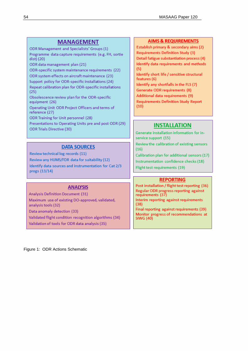
54 MASAAG Paper 120
Figure 1: ODR Actions Schematic

MASAAG Paper 120 55
Appendix B: Glossary of Terms
Structural Qualification: Structural qualification is a term which encompasses static strength,
fatigue substantiation and mechanical/dynamic stability. In the context of this paper, the primary
focus of structural qualification is fatigue substantiation.
Design Usage Spectrum: The design usage spectrum is the usage spectrum specified in the
design phase of the aircraft and is based on a conservative estimate of the percentage of total
flying time which will be spent in each flight regime when the aircraft is flown in its anticipated
operational role. The design usage spectrum may also include the frequency of occurrence of
fatigue significant events, such as: rotor starts, landings, transitions between steady-state
conditions and control reversals and in some cases pertinent details of mass and centre of
gravity configuration and density altitude distribution. The level of detail afforded to the design
spectrum is generally related to the development era, with older designs having a much more
limited range of flight conditions, events and relevant sub-distributions. More recent designs
generally have highly detailed spectra (because of the availability of improved computing power
for data processing and analysis). It should be noted that the design usage spectrum is usually
defined to envelope the worst-case usage within a platform type’s fleet; therefore, for many
individual platforms the design spectrum may be highly conservative.
In-Service Usage Spectrum: The in-service usage spectrum generally defines the way the
aircraft is used in the service environment. The service spectrum has traditionally been defined
with a reduced level of detail compared with the design usage spectrum. In its simplest form the
in-service usage spectrum may merely provide a distribution of sortie profile codes. The in-
service spectrum is usually defined in the SOIU, which is used to communicate the in-service
usage to the DO, for comparison with the design usage spectrum. Where possible, in-service
spectra will be confirmed or validated using quantitative data gathered during a triennial SOIU
review.
Usage Severity: Usage severity in the context of ODR is the measure of how damaging the
overall, or specific aspects of, usage is. Usage severity may be measured directly by inertia,
load or strain sensing instrumentation, or it may be inferred through indirect means such as rate
of change of aircraft motion or placement in a distribution of selected parameters. Usage
severity may be indicative or absolute, depending on the complexity and type of instrumentation

56 MASAAG Paper 120
fitted and will be designed to satisfy specific requirements, as determined by the programme
definition study.
Ground and Flight Load and/or Strain Survey: A programme of controlled ground and flight
events used to measure loads and/or strains by the use of dedicated instrumentation (often
involving strain gauging). The load/strain survey usually attempts to characterise and measure
the worst case fatigue loads/strains for each event or condition in the design spectrum for use in
the fatigue substantiation programme. Ground and flight load/strain surveys are undertaken in
highly controlled conditions, usually on a prototype or pre-production aircraft operated by one or
more DO test pilots. It is important to note that a flight loads survey / flight strain survey is the
primary mechanism for loads validation and is a key component of the design and
substantiation process.
Critical Structural Feature: Essential geometry where mechanical load and displacement are
transferred and which has been the subject of analysis/testing during the strength substantiation
programme. Such features may or may not have published service lives.
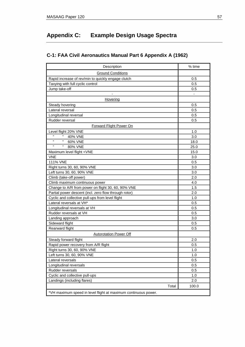
MASAAG Paper 120 57
Appendix C: Example Design Usage Spectra
C-1: FAA Civil Aeronautics Manual Part 6 Appendix A (1962)
Description % time
Ground Conditions
Rapid increase of rev/min to quickly engage clutch 0.5
Taxying with full cyclic control 0.5
Jump take-off 0.5
- -
Hovering
Steady hovering 0.5
Lateral reversal 0.5
Longitudinal reversal 0.5
Rudder reversal 0.5
Forward Flight Power On
Level flight 20% VNE 1.0
" " 40% VNE 3.0
" " 60% VNE 18.0
" " 80% VNE 25.0
Maximum level flight <VNE 15.0
VNE 3.0
111% VNE 0.5
Right turns 30, 60, 90% VNE 3.0
Left turns 30, 60, 90% VNE 3.0
Climb (take-off power) 2.0
Climb maximum continuous power 4.0
Change to A/R from power on flight 30, 60, 90% VNE 1.5
Partial power descent (incl. zero flow through rotor) 2.0
Cyclic and collective pull-ups from level flight 1.0
Lateral reversals at VH* 0.5
Longitudinal reversals at VH 0.5
Rudder reversals at VH 0.5
Landing approach 3.0
Sideward flight 0.5
Rearward flight 0.5
Autorotation Power Off
Steady forward flight 2.0
Rapid power recovery from A/R flight 0.5
Right turns 30, 60, 90% VNE 1.0
Left turns 30, 60, 90% VNE 1.0
Lateral reversals 0.5
Longitudinal reversals 0.5
Rudder reversals 0.5
Cyclic and collective pull-ups 1.0
Landings (including flares) 2.0
Total 100.0
*VH maximum speed in level flight at maximum continuous power.
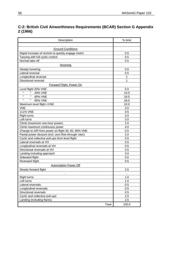
58 MASAAG Paper 120
C-2: British Civil Airworthiness Requirements (BCAR) Section G Appendix 2 (1966)
Description % time
Ground Conditions
Rapid increase of rev/min to quickly engage clutch 0.5
Taxying with full cyclic control 0.5
Normal take-off 0.5
Hovering
Steady hovering 0.5
Lateral reversal 0.5
Longitudinal reversal 1
Directional reversal 1
Forward Flight. Power On
Level flight 20% VNE 5.0
" " 40% VNE 10.0
" " 60% VNE 18.0
" " 80% VNE 18.0
Maximum level flight <VNE 10.0
VNE 3.0
111% VNE 0.5
Right turns 3.0
Left turns 3.0
Climb (maximum one-hour power) 2.0
Climb maximum continuous power 4.0
Change to A/R from power on flight 30, 60, 90% VNE 0.5
Partial power descent (incl. zero flow through rotor) 2.0
Cyclic and collective pull-ups from level flight 0.5
Lateral reversals at VH 0.5
Longitudinal reversals at VH 0.5
Directional reversals at VH 0.5
Landing including approach 3.0
Sideward flight 0.5
Rearward flight 0.5
Autorotation Power Off
Steady forward flight 2.5
- -
Right turns 1.0
Left turns 1.0
Lateral reversals 0.5
Longitudinal reversals 0.5
Directional reversals 0.5
Cyclic and collective pull-ups 2.0
Landing (including flares) 2.5
Total 100.0
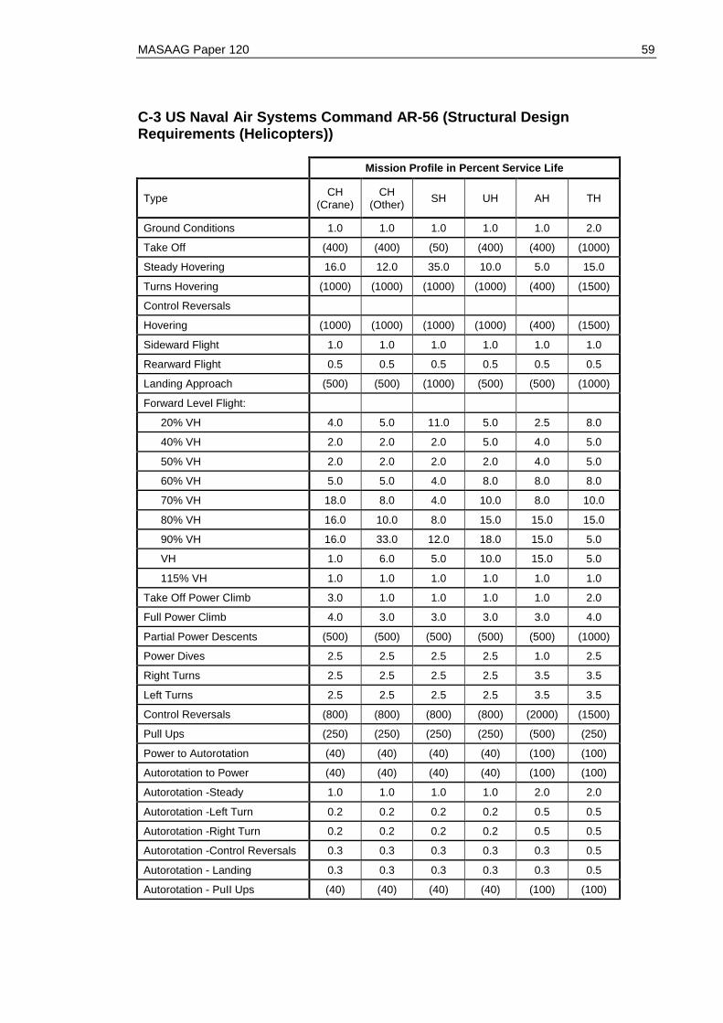
MASAAG Paper 120 59
C-3 US Naval Air Systems Command AR-56 (Structural Design Requirements (Helicopters))
Mission Profile in Percent Service Life
Type CH
(Crane) CH
(Other) SH UH AH TH
Ground Conditions 1.0 1.0 1.0 1.0 1.0 2.0
Take Off (400) (400) (50) (400) (400) (1000)
Steady Hovering 16.0 12.0 35.0 10.0 5.0 15.0
Turns Hovering (1000) (1000) (1000) (1000) (400) (1500)
Control Reversals
Hovering (1000) (1000) (1000) (1000) (400) (1500)
Sideward Flight 1.0 1.0 1.0 1.0 1.0 1.0
Rearward Flight 0.5 0.5 0.5 0.5 0.5 0.5
Landing Approach (500) (500) (1000) (500) (500) (1000)
Forward Level Flight:
20% VH 4.0 5.0 11.0 5.0 2.5 8.0
40% VH 2.0 2.0 2.0 5.0 4.0 5.0
50% VH 2.0 2.0 2.0 2.0 4.0 5.0
60% VH 5.0 5.0 4.0 8.0 8.0 8.0
70% VH 18.0 8.0 4.0 10.0 8.0 10.0
80% VH 16.0 10.0 8.0 15.0 15.0 15.0
90% VH 16.0 33.0 12.0 18.0 15.0 5.0
VH 1.0 6.0 5.0 10.0 15.0 5.0
115% VH 1.0 1.0 1.0 1.0 1.0 1.0
Take Off Power Climb 3.0 1.0 1.0 1.0 1.0 2.0
Full Power Climb 4.0 3.0 3.0 3.0 3.0 4.0
Partial Power Descents (500) (500) (500) (500) (500) (1000)
Power Dives 2.5 2.5 2.5 2.5 1.0 2.5
Right Turns 2.5 2.5 2.5 2.5 3.5 3.5
Left Turns 2.5 2.5 2.5 2.5 3.5 3.5
Control Reversals (800) (800) (800) (800) (2000) (1500)
Pull Ups (250) (250) (250) (250) (500) (250)
Power to Autorotation (40) (40) (40) (40) (100) (100)
Autorotation to Power (40) (40) (40) (40) (100) (100)
Autorotation -Steady 1.0 1.0 1.0 1.0 2.0 2.0
Autorotation -Left Turn 0.2 0.2 0.2 0.2 0.5 0.5
Autorotation -Right Turn 0.2 0.2 0.2 0.2 0.5 0.5
Autorotation -Control Reversals 0.3 0.3 0.3 0.3 0.3 0.5
Autorotation - Landing 0.3 0.3 0.3 0.3 0.3 0.5
Autorotation - PuII Ups (40) (40) (40) (40) (100) (100)
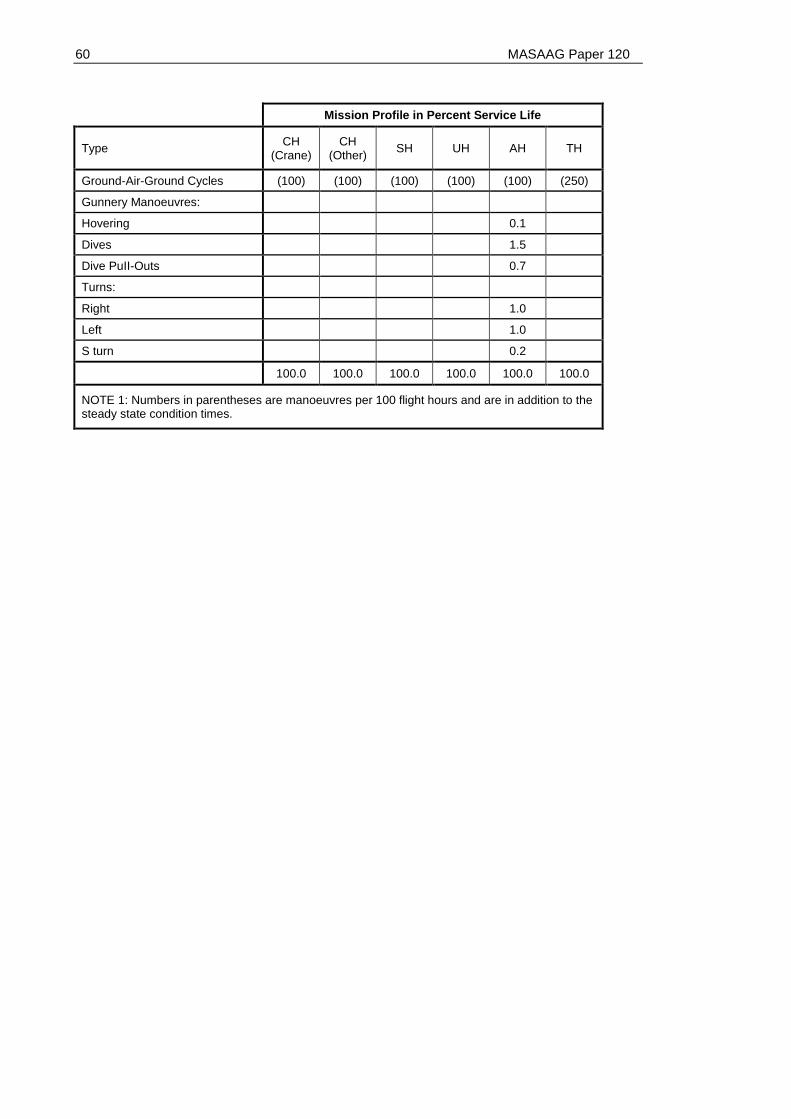
60 MASAAG Paper 120
Mission Profile in Percent Service Life
Type CH
(Crane) CH
(Other) SH UH AH TH
Ground-Air-Ground Cycles (100) (100) (100) (100) (100) (250)
Gunnery Manoeuvres:
Hovering 0.1
Dives 1.5
Dive PuII-Outs 0.7
Turns:
Right 1.0
Left 1.0
S turn 0.2
100.0 100.0 100.0 100.0 100.0 100.0
NOTE 1: Numbers in parentheses are manoeuvres per 100 flight hours and are in addition to the steady state condition times.

MASAAG Paper 120 61
Appendix D: Example Scripted Flight Schedule for FCR
Validation
FCR Validation Flight Schedule for ac Tail Number .......... Type ………. Date flown .............
Note: Where possible each steady FC (e.g. HIGE, HOGE) should be carried out for at least 1 min
Flight Conditions Measurements Remarks
1.Windspeed and
Direction Prior to Start
Kts...............
Direction...................
2. Main Rotor Engagement Time............................... RADALT (ft) =
3. Take Off Time …………………………… Press Alt (ft) =
4. Hover Inside Ground
Effect (IGE) into wind
Start Time ......................
Finish Time.......................
AGL (ft) =
5. Spot turns (IGE) (right) Start Time ......................
Finish Time.......................
AGL (ft) =
6. Hover Inside Ground
Effect (IGE) tailwind
Start Time ......................
Finish Time.......................
AGL (ft) =
7. Spot turns (IGE) (left) Start Time ......................
Finish Time.......................
AGL (ft) =
8. Landing (rotor running) Time …………………………… Press Alt (ft) =
9. Take Off Time ……………………………
10. Hover Outside Ground
Effect (OGE) into wind
Start Time ......................
Finish Time.......................
AGL (ft) =
11. Spot turns (OGE)
(right)
Start Time ......................
Finish Time.......................
AGL (ft) =
12. Hover Outside Ground
Effect (OGE) tailwind
Start Time ......................
Finish Time.......................
AGL (ft) =
13. Spot turns (OGE) (left) Start Time ......................
Finish Time.......................
AGL (ft) =
14. Sideways Flight (right)
(up to 20 kts estimated
Start Time ......................
Finish Time.......................
AGL (ft) =

62 MASAAG Paper 120
airspeed) – into wind
15. Sideways Flight (left)
(up to 20 knots estimated
airspeed) – into wind
Start Time ......................
Finish Time.......................
AGL (ft) =
16. Rearwards Flight (up
to 20 knots estimated
airspeed) – into wind
Start Time ......................
Finish Time.......................
AGL (ft) =
17. Landing (rotor running) Time
………………………………..
Press Alt (ft) =
18. Take Off Time…………………………………
19. Hover Inside Ground
Effect (IGE) into wind
Start Time ......................
Finish Time.......................
AGL (ft) =
20. Vertical Climb (>1000
ft) ground referenced
Start Time ......................
Finish Time.......................
Start AGL (ft) =
End AGL (ft) =
TQ(%) =
Climb Rate (ft/min) =
21. Partial Power Descent
(> 1000 ft)
Start Time ......................
Finish Time.......................
Start AGL (ft) =
End AGL (ft) =
Descent Rate (ft/min) =
22. Full Power Climb
(>1000 ft)
Start Time ......................
Finish Time.......................
Start AGL (ft) =
End AGL (ft) =
TQ(%) =
Climb Rate (ft/min) =
23. Standard training
circuit
Start Time ......................
Finish Time.......................
Circuit Description =
24. Downwind training
circuit
Start Time ......................
Finish Time.......................
Circuit Description =
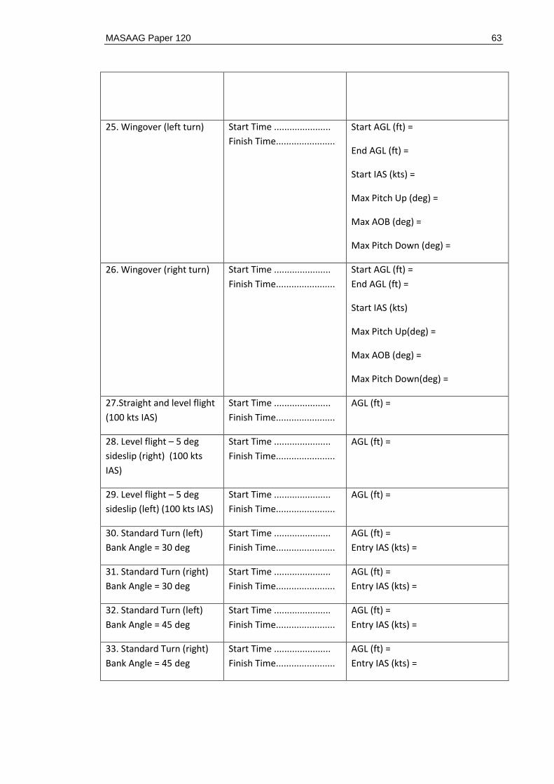
MASAAG Paper 120 63
25. Wingover (left turn) Start Time ......................
Finish Time.......................
Start AGL (ft) =
End AGL (ft) =
Start IAS (kts) =
Max Pitch Up (deg) =
Max AOB (deg) =
Max Pitch Down (deg) =
26. Wingover (right turn) Start Time ......................
Finish Time.......................
Start AGL (ft) =
End AGL (ft) =
Start IAS (kts)
Max Pitch Up(deg) =
Max AOB (deg) =
Max Pitch Down(deg) =
27.Straight and level flight
(100 kts IAS)
Start Time ......................
Finish Time.......................
AGL (ft) =
28. Level flight – 5 deg
sideslip (right) (100 kts
IAS)
Start Time ......................
Finish Time.......................
AGL (ft) =
29. Level flight – 5 deg
sideslip (left) (100 kts IAS)
Start Time ......................
Finish Time.......................
AGL (ft) =
30. Standard Turn (left)
Bank Angle = 30 deg
Start Time ......................
Finish Time.......................
AGL (ft) =
Entry IAS (kts) =
31. Standard Turn (right)
Bank Angle = 30 deg
Start Time ......................
Finish Time.......................
AGL (ft) =
Entry IAS (kts) =
32. Standard Turn (left)
Bank Angle = 45 deg
Start Time ......................
Finish Time.......................
AGL (ft) =
Entry IAS (kts) =
33. Standard Turn (right)
Bank Angle = 45 deg
Start Time ......................
Finish Time.......................
AGL (ft) =
Entry IAS (kts) =

64 MASAAG Paper 120
34. Steep Autorotation to
flare (end at hover)
Start Time ......................
Finish Time.......................
Start AGL (ft) =
End AGL (ft) =
Max descent rate (ft/min) =
35. Shallow Autorotation
(max range) to overshoot
Start Time ......................
Finish Time.......................
Start AGL (ft) =
End AGL (ft) =
Max descent rate (ft/min) =
36. Autorotational Turn to
hover
Start Time ......................
Finish Time.......................
Start AGL (ft) =
End AGL (ft) =
Max descent rate (ft/min) =
Max AOB (during turn) (deg) =
37. Quickstop (into wind) Start Time ......................
Finish Time.......................
Start AGL (ft) =
End AGL (ft) =
Start IAS (kts) =
38. Quickstop (downwind) Start Time ......................
Finish Time.......................
Start AGL (ft) =
End AGL (ft) =
Start IAS (kts) =
39. Main Rotor Shutdown Time...............................
40. Rotor Brake Applied Time...............................
41. Windspeed and
Direction at Shut Down
Kts...............
Direction...................
End of Paper
Recommended