Ground Operations Safety Manual
1 Issue 1 Revision 1
Ground Operations
Safety Manual
Changi Airport Group | PO Box 168, Singapore Changi Airport, Singapore 918146
www.changiairportgroup.com
Ground Operations Safety Manual
2 Issue 1 Revision 1
Amendment Records The amendments listed below have been incorporated into this copy of the Ground Operations Safety
Manual.
Serial
No.
Issue
No.
Revision
No. Description of Change Effective Date
1 0 0 Initial Issue 09 Jul 2014
2 0 1
Inclusion of Annexes IV to VI
Annex IV: Aircraft Engine Run-Up
Annex V: Compass Swing Calibration Check
Annex VI: General Guidelines on Washing of
Aircraft Exteriors in Changi Airport
15 Aug 2014
3 0 2
Part 1 – Introduction
• Revised text: Subsections 5.3 and 5.5.2
• Revised text and picture: Subsections 6.1
• Inserted Section 7: Equipment Staging
Area (ESA)
• Amendment to section numbering:
Sections 7 to 14 are now Sections 8 to 15
respectively
08 May 2015
4 0 3
Part 8 – Ramp Supervision
• Addition of Part 8 section on ramp
supervision
• Addition of Annex VII on IGOM’s
recommendations
18 Oct 2016
5 0 3 Part 5 – Aircraft Pushback
• Addition text: Subsections 5.3.5 to 5.3.7 18 Oct 2016
6 0 3 Part 6 – Aircraft Towing
• Insert text: Subsections 6.4(i)
• Insert text: Subsections 6.4(m)
18 Oct 2016
7 0 4
Part 9 – Training & Competency of GSP Personnel
• Safety training programme
• Functional safety training programme
• Structure of training programme
• Documentation
5 May 2017
8 0 4
Part 10 – Ground Service Equipment Maintenance
• Preventive and corrective maintenance
• Treatment of unserviceable GSE
• Documentation
5 May 2017
Ground Operations Safety Manual
3 Issue 1 Revision 1
• Airfield Vehicle Permit requirements
9 1 0
Part 1 – Introduction
• Inserted section 1.3: Oversight Framework
• Inserted section 1.4: Updating of GOSM
Part 2 – Safety Management System
• Added chapter on SMS
Part 3 – Human Factors
• Added chapter on human factors
Part 4 – Safety Culture
• Added chapter on safety culture
Part 5 – General Safety Guidelines
• Inserted subsection 5.1.2: Overlapping
ERA & “keep clear” zones
• Inserted subsection 5.2.4: Mandatory
deployment of wheel chocks/stabilizers
• Inserted subsection 5.3.1: High visibility
safety vest and raincoat specifications
• Inserted subsection 5.4.1: Storm and
lightning
• Inserted subsection 5.4.2: Strong wind
conditions
• Inserted subsection 5.4.3: Low visibility
conditions
• Amended section 5.6: FOD
Part 6 – Standard Operating Procedures
• Added chapter on SOPs
Part 7 – ADGS/ Manual Marshalling
• Inserted section 7.3: Arrival OIC roles and
responsibilities
Part 8 – Operation of PLB
• Amended section 8.2: Arrival handling
Part 9 – Operation of GSE Associated with AHL
• Inserted section 9.2: General safety
instructions
• Inserted section 9.3: GSE operations
• Inserted section 9.6: Grounding of aircraft
17 Aug 2018
Ground Operations Safety Manual
4 Issue 1 Revision 1
Part 10 – Aircraft Pushback
• Inserted section 10.3: Departure OIC roles
and responsibilities
• Amended section 10.4.2: Towbarless
airtug operations
Part 11 – Aircraft Towing
• Amended section 11.2: Towing
requirements
Part 12 – Aircraft Fuelling
• Inserted section 12.2: Fuelling Vehicles
Safety Driving & Parking Inside ERA
• Inserted section 12.3: Pre-fuelling
operations
• Inserted section 12.4: Fuelling operations
Part 13 – Training & Competency of Personnel of
GSPs
• Inserted section 13.3: Refresher training
requirements
• Inserted section 13.5: Competency of
trainer, assessor, buddy for OJT
Part 14 – GSE Maintenance Programme
• Inserted section 14.2: Preventive
maintenance
• Inserted section 14.5: Fire protection
Part 15 – Contractor Management
• Added chapter on contractor management
10 1 1
Part 1 – Introduction
• Revised text Subsections 1.4.2.1: GOSM
updates
• Inserted section 1.4.2.3: Incorporation of
AONs
Part 2 – General Safety Guidelines
• Inserted section 5.2.1.2: Vehicle reverse
sensors and in-vehicle camera
• Revised text: subsection 5.3.2.1g),h)
• Amended section 5.5.3.1: Removal of
chocks
04 Dec 2019
Ground Operations Safety Manual
5 Issue 1 Revision 1
• Revised text: Section 5.6.4.1 to 5.6.4.3
Part 3 – Standard Operating Procedures
• Amended subsection 6.3.3.1: Pre-arrival
• Amended subsection 6.4.3.1: Departure
Part 4 – ADGS/ Manual Marshalling
• Amended subsection 7.1k): Pre-arrival
Handling
Part 5 – Operation of PLB
• Amended subsection 8.1c): Pre-arrival
Handling
• Amended subsection 8.3k): Departure
Handling
Part 6 – Operation of GSE Associated with AHL
• Amended section 9.1: Introduction
• Inserted subsection 9.2.1a): Valid AVP &
fire extinguisher
• Inserted subsection 9.2.2c): Minimum Safe
Distance
• Inserted section: 9.3.7 – 9.3.9: Keep clear
of refuelling hoses
• Inserted subsection 9.3.7.1i): Operating
towable skyloader
• Inserted subsection 9.3.8.1g): Snail speed
operation of loading GSEs
• Inserted subsection 9.4e): Tail support
stachion
• Amended section 9.6.3: Removal of
grounding cables
Part 7 – Aircraft Pushback
• Amended section 10.1: Pre-departure
Handling
Part 8 – Aircraft Towing
• Amended section 11.1.1: Towing
Operations
• Inserted section 11.1.1: Maximum towing
speed
Ground Operations Safety Manual
6 Issue 1 Revision 1
• Amended subsection 11.3.1g): Towing
manoeuvring speed limit
Part 9 – Aircraft Fuelling
• Amended subsection 12.1.2f): Reporting of
fuel spills
• Revised section 12.4: Fuelling operations
• Revised section 12.5: Aircraft fuel spillage
Part 10 – Training & Competency of Personnel of
GSPs
• Inserted section 13.5.4: Currency of GSPs
trainers
Part 11 – Annex V: Washing of Aircraft Exteriors in
Changi Airport
• Revised section 1.1: Aircraft Stands fitted
with grease/oil separators
Part 12 – Annex VII: Exceptions to PLB wheel
positions
• Inserted section 1: PLB wheel positions for
pre-arrival/arrival
• Inserted section 2: PLB wheel positions for
pre-departure/departure
Ground Operations Safety Manual
7 Issue 1 Revision 1
TABLE OF CONTENTS
Amendment Records ................................................................................................................... 2
Glossary..................................................................................................................................... 10
1 Introduction ....................................................................................................................... 12
1.1 Purpose and Scope ................................................................................................................ 12
1.2 Applicability ........................................................................................................................... 12
1.3 Oversight Framework............................................................................................................ 13
1.4 Updating of Ground Operations Safety Manual ................................................................... 13
2 Safety Management System ............................................................................................... 15
2.1 Introduction to SMS .............................................................................................................. 15
2.2 Components of a Safety Management System..................................................................... 15
3 Human Factors ................................................................................................................... 16
3.1 Introduction .......................................................................................................................... 16
4 Safety Culture ..................................................................................................................... 17
4.1 Introduction .......................................................................................................................... 17
5 General Safety Guidelines ................................................................................................... 18
5.1 Airside Locations ................................................................................................................... 18
5.2 Operating Vehicles and Motorised Ground Support Equipment at The Apron.................... 20
5.3 General Conduct of Ramp Personnel .................................................................................... 24
5.4 Adverse Weather Conditions ................................................................................................ 26
5.5 Use of Aircraft Wheel Chocks and Safety Cones ................................................................... 27
5.6 Foreign Object Debris ........................................................................................................... 31
6 Standard Operating Procedures .......................................................................................... 35
6.1 Introduction .......................................................................................................................... 35
6.2 Standardized Ramp Handling Procedure for Aircraft Arrival and Departure ....................... 35
6.3 Arrival OIC Roles and Responsibilities ................................................................................... 36
6.4 Departure OIC Roles and Responsibilities............................................................................. 39
7 Aircraft Docking Guidance System/ Manual Marshalling ...................................................... 44
7.1 Pre-arrival Handling .............................................................................................................. 44
7.2 Arrival Handling ..................................................................................................................... 44
8 Operation of Passenger Loading Bridge ............................................................................... 45
8.1 Pre-arrival Handling .............................................................................................................. 45
8.2 Arrival Handling ..................................................................................................................... 46
Ground Operations Safety Manual
8 Issue 1 Revision 1
8.3 Departure Handling ............................................................................................................... 47
9 Operation of Ground Support Equipment Associated with Aircraft Handling and Loading ..... 48
9.1 Introduction .......................................................................................................................... 48
9.2 General Safety Instructions ................................................................................................... 48
9.3 GSE Operations ..................................................................................................................... 49
9.4 Aircraft Ground Stability ....................................................................................................... 52
9.5 Low-wing aircraft (e.g. B737) ................................................................................................ 52
9.6 Grounding of Aircraft ............................................................................................................ 52
9.7 Aircraft Departure ................................................................................................................. 53
10 Aircraft Pushback ............................................................................................................... 54
10.1 Pre-departure Handling ........................................................................................................ 54
10.2 Departure Handling ............................................................................................................... 54
10.3 Pushback Operations ............................................................................................................ 55
10.4 Remote-Controlled Pushback Operation .............................................................................. 56
11 Aircraft Towing ................................................................................................................... 57
11.1 Operations ............................................................................................................................ 57
11.2 Towing Requirements ........................................................................................................... 58
11.3 Towing Manoeuvring ............................................................................................................ 58
11.4 Manoeuvring During Adverse Weather Conditions .............................................................. 60
11.5 Radio Telephony Failure During Towing ............................................................................... 60
11.6 Wingwalker ........................................................................................................................... 60
11.7 Incidents During Towing ....................................................................................................... 60
12 Aircraft Fuelling .................................................................................................................. 62
12.1 General .................................................................................................................................. 62
12.2 Fuelling Vehicles Safety Driving & Parking Inside ERA .......................................................... 62
12.3 Pre-fuelling Operations ......................................................................................................... 63
12.4 Fuelling Operations ............................................................................................................... 63
12.5 Aircraft Fuel Spillage ............................................................................................................. 64
13 Training & Competency of Personnel of Ground Service Providers ....................................... 65
13.1 Introduction .......................................................................................................................... 65
13.2 Programme Content ............................................................................................................. 65
13.3 Refresher Training Requirements ......................................................................................... 67
13.4 Documentation ..................................................................................................................... 67
Ground Operations Safety Manual
9 Issue 1 Revision 1
13.5 Competency of Trainer, Assessor, Buddy for the On-Job Training ....................................... 68
13.6 Training for Aircraft Docking Guidance Systems/Manual Marshalling ................................. 69
13.7 Training for Passenger Loading Bridge Operations ............................................................... 69
14 Ground Support Equipment Maintenance Programme ........................................................ 70
14.1 General .................................................................................................................................. 70
14.2 Maintenance Programme ..................................................................................................... 70
14.3 Treatment of Unserviceable GSE .......................................................................................... 70
14.4 Fire Protection ...................................................................................................................... 71
15 Contractor Management ..................................................................................................... 72
15.1 General .................................................................................................................................. 72
ANNEX I - IMPORTANT CONTACT INFORMATION ........................................................................ 73
ANNEX II - AIRCRAFT MARSHALLING SIGNALS ............................................................................. 74
ANNEX III - AIRCRAFT ENGINE RUN-UP ....................................................................................... 93
ANNEX IV - COMPASS SWING CALIBRATION (CSC) CHECK ............................................................ 96
ANNEX V .................................................................................................................................... 99
GENERAL GUIDELINES ON WASHING OF AIRCRAFT EXTERIORS IN CHANGI AIRPORT .................... 99
ANNEX VI – MARS LAYOUT ....................................................................................................... 100
ANNEX VII – EXCEPTIONS TO PLB WHEEL POSITIONS ................................................................. 101
Ground Operations Safety Manual
10 Issue 1 Revision 1
Glossary ACC Airside Control Centre
ADGS Aircraft Docking Guidance System
ADP Airside Driving Permit
AES Airport Emergency Services
AMC Airside Management Centre
APU Auxiliary Power Unit
AVP Airside Vehicle Permit
CAAS Civil Aviation Authority of Singapore
CAFHI Changi Airport Fuel Hydrant Installation
CAG Changi Airport Group
CCTV Closed-Circuit TeleVision camera
DAA Delivery At Arrival
ERA Equipment Restraint Area
ESA Equipment Staging Area
ETA Estimated Time of Arrival
FOD Foreign Object Debris
FSM Fire Safety Manual
FSZ Fuelling Safety Zone
GOSM Ground Operations Safety Manual
GPU Ground Power Units
GSE Ground Service Equipment
GHA
GSPs
Ground Handling Agent
Ground Service Providers
IATA International Air Transport Association
IGOM IATA Ground Operations Manual
Ground Operations Safety Manual
11 Issue 1 Revision 1
JCPL Joint Container Pallet Loader
MARS Multiple Aircraft Receiving Stand
MDL Main Deck Loader
PDA Personal Digital Assistant
PEDs Portable Electronic Devices
PLB Passenger Loading Bridge
RT Radio Telephony
SOPs Standard Operating Procedures
TEP Temporary Entry Permit
ULDs Unit Load Devices
VHF Very High Frequency
Ground Operations Safety Manual
12 Issue 1 Revision 1
1 Introduction
1.1 Purpose and Scope
1.1.1 With effect from 9 July 2014, the Ground Operations Safety Manual (GOSM) supersedes the
Responsibilities of Ground Handling Personnel Manual.
1.1.2 The CAG Airside GOSM defines CAG’s ground handling safety standards for GSPs at Changi
Airport to ensure ground operation activities are safely accomplished. It defines the
minimum ground handling standards and procedures to operate safely at Changi Airport.
1.1.3 In doing so, CAG seeks to mitigate safety risks of the following ground operational activities:
(a) Aircraft Power-In Arrival and Aircraft Power-Out Departure*;
(b) Aircraft Powerback*;
(c) Aircraft Marshalling;
(d) Operation of Passenger Loading Bridge;
(e) Operation of GSE Associated with Aircraft Handling and Loading;
(f) Aircraft Pushback;
(g) Aircraft Towing;
(h) Aircraft Fuelling.
Note: *Not applicable to Changi Airport
If any function is outsourced to an external third party, the GSP shall establish direct
oversight to ensure that the function is conducted safely.
1.2 Applicability
1.2.1 This document shall be used by GSPs at Changi Airport as one of the main documents in the
conduct of ground handling functions.
1.2.2 The GSP shall notify CAG of any deviations from the published GOSM.
1.2.3 This document will provide the basis for which CAG airside inspections and audits will be
conducted.
1.2.4 All standards in this document always contain the word “shall” to denote a requirement. For
recommended practices, they will be represented by the word “should”.
Ground Operations Safety Manual
13 Issue 1 Revision 1
1.3 Oversight Framework
1.3.1 The CAG oversight framework consists of safety inspections, performance reports and
audits.
1.3.1.1 Safety inspections
1.3.1.1.1 Monthly inspections are conducted on the six activities stated in 1.1.3. Non-conformance
to SOPs are identified and shared with GSPs. GSPs are required to follow up and revert
with corrective actions.
1.3.1.2 Performance reports
1.3.1.2.1 The quarterly airside safety report summarizes the inspection performance of the GSPs
and are shared with the GSPs’ senior management.
1.3.1.3 Audits
1.3.1.3.1 All GSPs operating in Changi Airport shall attain a recognized industry standard
certification (e.g. ISAGO, JIG).
1.3.1.3.2 The safety system audit will be conducted on a biennial basis on GSPs with recognized
industry standard certification. Otherwise, the audit will be conducted on an annual basis
till the GSP attains its industry standard certification.
1.4 Updating of Ground Operations Safety Manual
1.4.1 Procedure
1.4.1.1 The updating of the GOSM is scheduled annually and seeks consultation from respective
subject matter officers for their relevant inputs. All relevant stakeholders’ agreement
should be obtained.
1.4.1.2 A gap analysis shall also be conducted with the IATA Airport Handling Manual (AHM) and
IATA Ground Operations Manual (IGOM) published each year. The respective subject
matter officers are required to identify the new updates relevant to their subject and
engage the stakeholders on the appropriateness to incorporate in the GOSM before
submitting their inputs to Airside Management.
1.4.2 Incorporation of Airside Operations Notices and Airside Safety Notices
1.4.2.1 All relevant Airside Operations Notices (AONs) and Airside Safety Notices (ASNs) will be
included in the Ground Operation Safety Manual (GOSM) during the annual update.
1.4.2.2 Prior to the promulgation of the updated GOSM, the AONs and ASNs remain valid and all
GSPs are required to comply with the stated safety procedures and requirements.
Ground Operations Safety Manual
14 Issue 1 Revision 1
1.4.2.3 GSPs shall exercise due diligence to ensure prompt submission of evidence to CAG to
demonstrate that they incorporate the content of AONs involving changes to ground
handling procedures, to their SOPs and training materials when the AONs are published.
1.4.3 Change Request
1.4.3.1 In situations where certain procedures and standards may have to change to cope with the
new safety and operational challenges, the GSPs are welcome to propose any changes by
writing in to CAG, Airside Management.
1.4.4 References
1.4.4.1 The GOSM refers to the following documents:
a) Airport Handling Manual, 38th Edition;
b) Airside Driving Theory Handbook, 3rd Edition;
c) Civil Aviation Authority of Singapore (Changi Airport) By-Laws 2009;
d) IATA Ground Operations Manual (IGOM), 7th Edition;
e) ISAGO Standards Manual, 7th Edition (Effective February 2018);
f) EN ISO 20471:2013, New Standard for High Visibility Clothing.
Ground Operations Safety Manual
15 Issue 1 Revision 1
2 Safety Management System
2.1 Introduction to SMS
2.1.1 The Safety Management System (SMS) is a framework of policies, processes, procedures and
techniques for an organisation to monitor and continuously improve its safety performance
by making informed decisions on the management of operational safety risks. Specifications
for an SMS are derived from global standards as stipulated in ICAO Annex 19.
2.1.2 All GSPs operating in Changi Airport shall have an SMS. Refuelling agents are allowed to
adopt a different safety framework e.g. Health, Safety, Security and Environment (HSSE),
which serves the same purposes as an SMS.
2.2 Components of a Safety Management System
2.2.1 The ICAO Annex 19 SMS framework specifies four components that make up the basic
structure of an SMS.
2.2.1.1 Component 1 – Safety policy and objectives, which detail the organizational and
administration aspects of the SMS, including the assignment of roles and responsibilities.
2.2.1.2 Component 2 – Safety risk management, which details the method of collecting safety
information (hazard identification), assessing the safety risks and determination of any
necessary control measures.
2.2.1.3 Component 3 – Safety assurance, which details the monitoring of safety performance,
particularly those actions associated with the outcome of safety risk management, and any
actions taken to improve safety performance.
2.2.1.4 Component 4 – Safety promotion, which details the processes in place to handle and
disseminate safety information and maintain safety competence and awareness in key
personnel.
Ground Operations Safety Manual
16 Issue 1 Revision 1
3 Human Factors
3.1 Introduction
3.1.1 Human factors is a science that pays attention to physical, psychological, and other human
attributes to ensure that tasks are completed safely and efficiently with minimal risk to
personnel and equipment. Most apron accidents and incidents involve to a certain degree
human error or violation of company policies, processes or procedures. Examples of human
factors for consideration are:
a) Safety culture;
b) Human performance limitations;
c) Environmental considerations;
d) Procedures, information, tools and task sign-off practices;
e) Procedural non-compliance;
f) Planning for tasks and equipment;
g) Injury prevention;
h) Fatigue/alertness management;
i) Shift and task turnover;
j) Error prevention strategies.
3.1.2 GSPs should incorporate human factors as part of the SMS.
Ground Operations Safety Manual
17 Issue 1 Revision 1
4 Safety Culture
4.1 Introduction
4.1.1 Organisational safety culture sets the boundaries for acceptable behaviour in the workplace
by establishing the behavioural norms and limits. These cultures provide the cornerstone for
managerial and employee decision making.
4.1.2 Having a safety culture reflects senior management’s commitment to safety. Senior
management’s attitude towards safety influences the employee’s positive approach to
safety and shared beliefs, practices and attitudes. The tone for safety culture is set and
driven by the words and actions of senior management during implementation of a “Just
Culture” process, which ensures fairness and open reporting in dealing with human error.
4.1.3 A positive safety culture demonstrates the following attributes:
a) Senior management visibly demonstrates their commitment to their Safety
Management System;
b) Those in senior positions consistently foster a climate in which there is encouragement
towards, comments and feedback from all levels of the organisation on safety matters;
c) There is an organizational policy regarding incident reporting (occupational and aviation
safety) which encourages an open reporting culture where staff reports all safety events.
There is a clear statement within the policy regarding management response to
incidents, in particular whether it operates a just culture policy;
d) It provides a clear distinction between what are acceptable and what are unacceptable
behaviours, and people are treated accordingly;
e) There is a requirement to communicate safety information at all levels of the
organisation. A communication infrastructure is developed and implemented;
f) There are policies and procedures documenting the identification of the hazards and
assessment of risks associated with these hazards exist and are accessible;
g) Personnel are trained and understand the safety event reporting policy within their
organisation;
h) Lessons learned from previous incidents are shared and included in training content to
promote improvement of the safety programme;
i) An employee feedback system is established as part of the safety management system.
4.1.4 GSPs should cultivate a safety culture as part of the SMS.
Ground Operations Safety Manual
18 Issue 1 Revision 1
5 General Safety Guidelines
5.1 Airside Locations
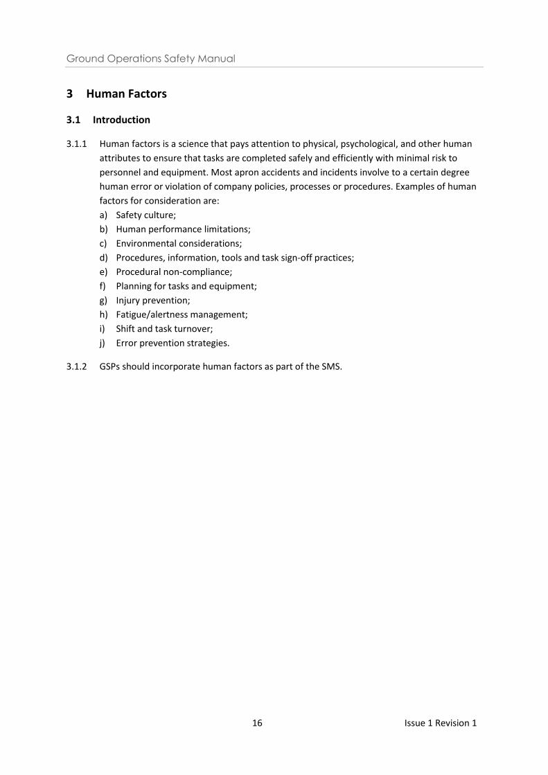
5.1.1 Equipment Restraint Area (ERA) & Equipment Restraint Line
5.1.1.1 The ERA is defined as the area of the apron bordered by a red line. It shall be kept clear at
all times for the safe movement of an aircraft in and out of the stand. Personnel, vehicles
and/or GSE are only allowed to enter when servicing the aircraft or for other work
purposes.
Sample of Equipment Restraint Area
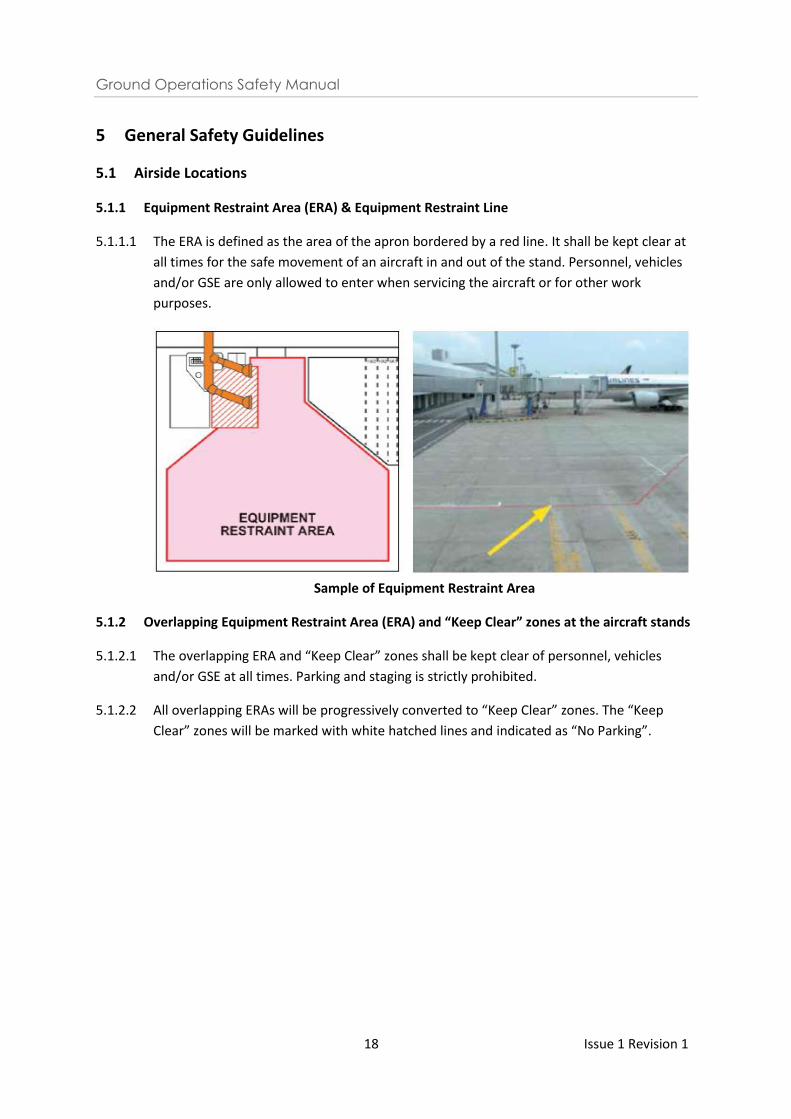
5.1.2 Overlapping Equipment Restraint Area (ERA) and “Keep Clear” zones at the aircraft stands
5.1.2.1 The overlapping ERA and “Keep Clear” zones shall be kept clear of personnel, vehicles
and/or GSE at all times. Parking and staging is strictly prohibited.
5.1.2.2 All overlapping ERAs will be progressively converted to “Keep Clear” zones. The “Keep
Clear” zones will be marked with white hatched lines and indicated as “No Parking”.
Ground Operations Safety Manual
19 Issue 1 Revision 1
Sample of “Keep Clear” zones
5.1.2.3 Personnel who are handling aircraft operations at the aircraft stand and adjacent stands
shall perform pre-arrival and pre-departure FOD checks* and remove any FOD from the
“Keep Clear” zone.
*Note: Refer to Section 5.6.4.1 – 5.6.4.3 for the conduct of FOD walk.
5.1.2.4 The ADGS operator/manual marshaller (i.e. Arrival OIC) and headset man (Departure OIC)
shall ensure that the ERA and the adjacent “Keep Clear” zones are clear of any obstruction
prior to arrival and pushback of aircraft.
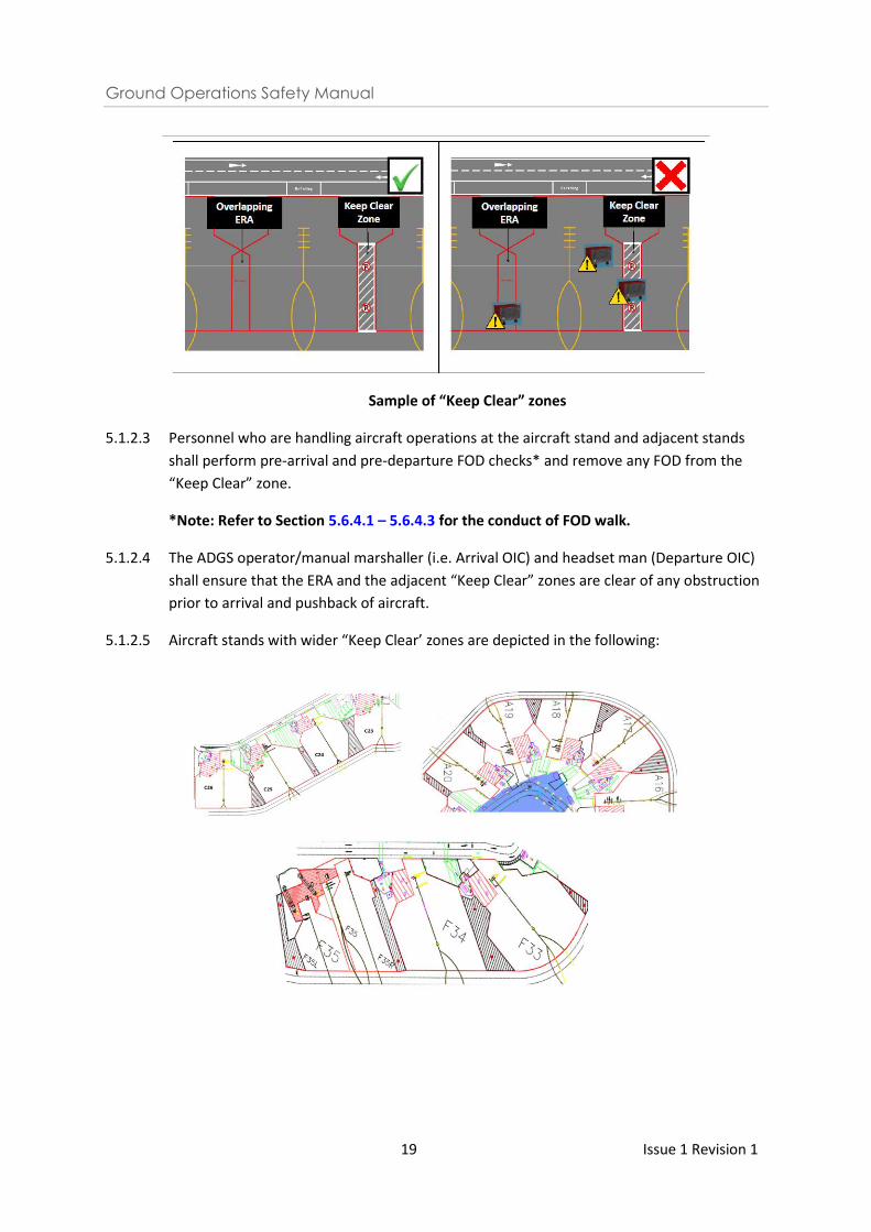
5.1.2.5 Aircraft stands with wider “Keep Clear’ zones are depicted in the following:
Ground Operations Safety Manual
20 Issue 1 Revision 1
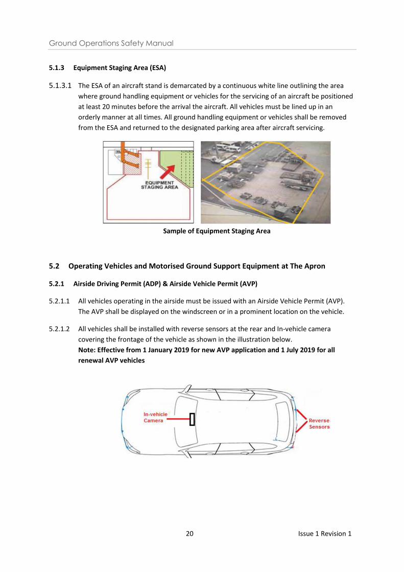
5.1.3 Equipment Staging Area (ESA)
5.1.3.1 The ESA of an aircraft stand is demarcated by a continuous white line outlining the area
where ground handling equipment or vehicles for the servicing of an aircraft be positioned
at least 20 minutes before the arrival the aircraft. All vehicles must be lined up in an
orderly manner at all times. All ground handling equipment or vehicles shall be removed
from the ESA and returned to the designated parking area after aircraft servicing.
Sample of Equipment Staging Area
5.2 Operating Vehicles and Motorised Ground Support Equipment at The Apron
5.2.1 Airside Driving Permit (ADP) & Airside Vehicle Permit (AVP)
5.2.1.1 All vehicles operating in the airside must be issued with an Airside Vehicle Permit (AVP).
The AVP shall be displayed on the windscreen or in a prominent location on the vehicle.
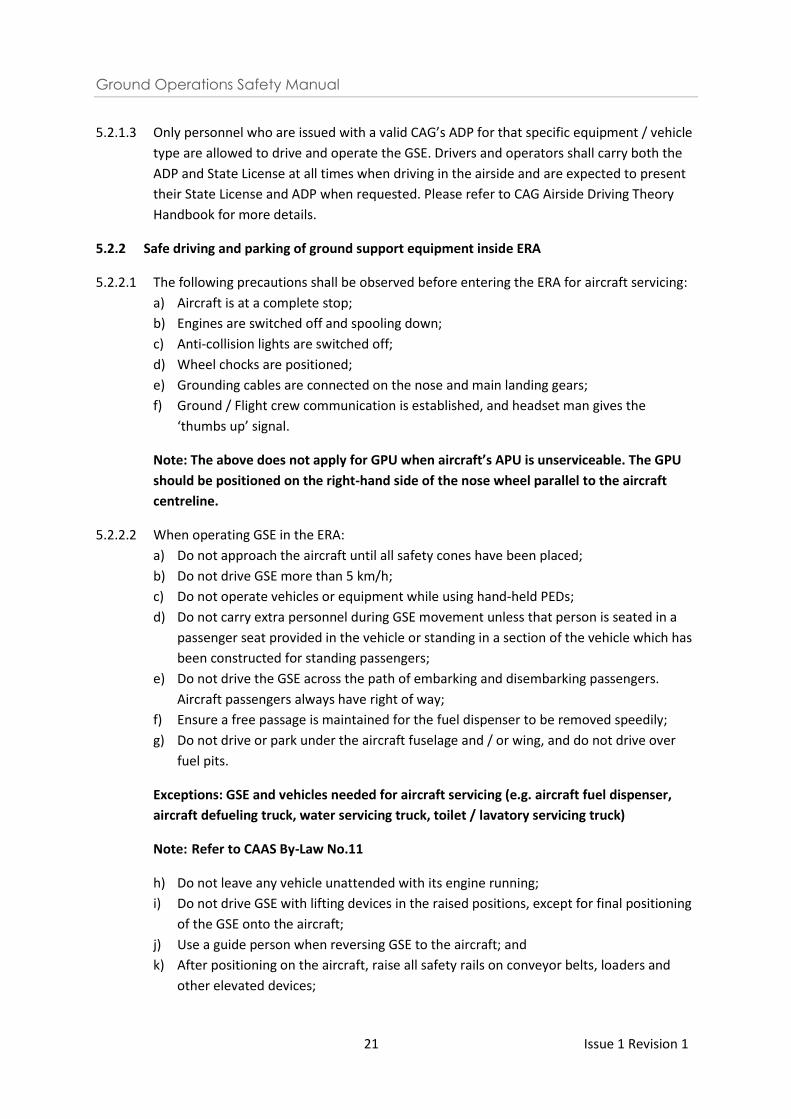
5.2.1.2 All vehicles shall be installed with reverse sensors at the rear and In-vehicle camera
covering the frontage of the vehicle as shown in the illustration below.
Note: Effective from 1 January 2019 for new AVP application and 1 July 2019 for all
renewal AVP vehicles
Ground Operations Safety Manual
21 Issue 1 Revision 1
5.2.1.3 Only personnel who are issued with a valid CAG’s ADP for that specific equipment / vehicle
type are allowed to drive and operate the GSE. Drivers and operators shall carry both the
ADP and State License at all times when driving in the airside and are expected to present
their State License and ADP when requested. Please refer to CAG Airside Driving Theory
Handbook for more details.
5.2.2 Safe driving and parking of ground support equipment inside ERA
5.2.2.1 The following precautions shall be observed before entering the ERA for aircraft servicing:
a) Aircraft is at a complete stop;
b) Engines are switched off and spooling down;
c) Anti-collision lights are switched off;
d) Wheel chocks are positioned;
e) Grounding cables are connected on the nose and main landing gears;
f) Ground / Flight crew communication is established, and headset man gives the
‘thumbs up’ signal.
Note: The above does not apply for GPU when aircraft’s APU is unserviceable. The GPU
should be positioned on the right-hand side of the nose wheel parallel to the aircraft
centreline.
5.2.2.2 When operating GSE in the ERA:
a) Do not approach the aircraft until all safety cones have been placed;
b) Do not drive GSE more than 5 km/h;
c) Do not operate vehicles or equipment while using hand-held PEDs;
d) Do not carry extra personnel during GSE movement unless that person is seated in a
passenger seat provided in the vehicle or standing in a section of the vehicle which has
been constructed for standing passengers;
e) Do not drive the GSE across the path of embarking and disembarking passengers.
Aircraft passengers always have right of way;
f) Ensure a free passage is maintained for the fuel dispenser to be removed speedily;
g) Do not drive or park under the aircraft fuselage and / or wing, and do not drive over
fuel pits.
Exceptions: GSE and vehicles needed for aircraft servicing (e.g. aircraft fuel dispenser,
aircraft defueling truck, water servicing truck, toilet / lavatory servicing truck)
Note: Refer to CAAS By-Law No.11
h) Do not leave any vehicle unattended with its engine running;
i) Do not drive GSE with lifting devices in the raised positions, except for final positioning
of the GSE onto the aircraft;
j) Use a guide person when reversing GSE to the aircraft; and
k) After positioning on the aircraft, raise all safety rails on conveyor belts, loaders and
other elevated devices;
Ground Operations Safety Manual
22 Issue 1 Revision 1
l) Make a minimum of one complete stop with all motorized vehicles / equipment prior
to entering the ERA:
i. Conduct a “Brake Check” or “Safety Stop” by coming to a full and complete stop
to confirm the serviceability of the brake system on the vehicle and to test the
apron surface. This action shall be carried out even if there is no ERA marked on
the apron;
ii. This stop shall be conducted at a distance no less than 5 metres from the
aircraft.
m) Manoeuvre GSE carefully to prevent personnel injury and / or aircraft damage;
n) When reversing vehicles or equipment with limited rear-view visibility inside the ERA:
i. Be guided by an agent using standard IATA signals, and / or;
ii. Be assisted by means of a rear-view video or mirror.
Note: Marshaller must position himself to the obstacle and maintain the line of
sight with the driver.
5.2.3 Breakdown of GSE within the ERA
5.2.3.1 In the event of a breakdown of a GSE within the aircraft stand, operators shall:
a) Not leave the GSE unattended;
b) Immediately inform CAG ACC; and
c) Arrange for the immediate removal of the GSE and ensure that aircraft handling
operations are not obstructed.
5.2.4 Mandatory deployment of wheel chocks/stabilisers on motorised ground support
equipment
5.2.4.1 Correct deployment of wheel chocks/stabilisers on motorised GSE can prevent inadvertent
rolling forward/backward of equipment, or when in-built braking mechanism malfunctions.
5.2.4.2 The following motorised GSEs shall at all times, be deployed with wheel chocks/stabilisers
when docked onto the aircraft or when parked in the airside:
a) Tractor;
b) Water truck;
c) Lavatory truck;
d) Ballymore;
e) Hi-Lift;
f) Lower deck loader;
g) Main deck loader;
h) Ground power unit;
i) Air starter unit;
j) Fuel truck;
k) Air-conditioned unit (including towable unit);
l) Belt loader (including towable belt loader);
m) Passenger stairs (including towable passenger stairs).
Ground Operations Safety Manual
23 Issue 1 Revision 1
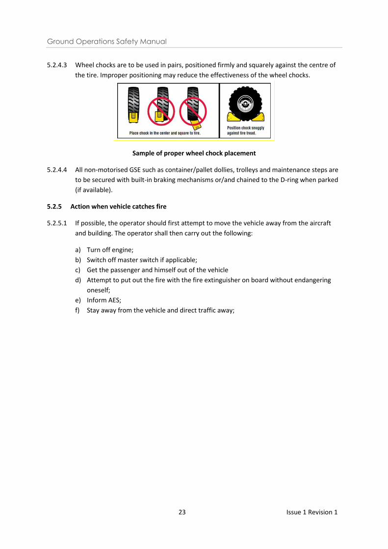
5.2.4.3 Wheel chocks are to be used in pairs, positioned firmly and squarely against the centre of
the tire. Improper positioning may reduce the effectiveness of the wheel chocks.
Sample of proper wheel chock placement
5.2.4.4 All non-motorised GSE such as container/pallet dollies, trolleys and maintenance steps are
to be secured with built-in braking mechanisms or/and chained to the D-ring when parked
(if available).
5.2.5 Action when vehicle catches fire
5.2.5.1 If possible, the operator should first attempt to move the vehicle away from the aircraft
and building. The operator shall then carry out the following:
a) Turn off engine;
b) Switch off master switch if applicable;
c) Get the passenger and himself out of the vehicle
d) Attempt to put out the fire with the fire extinguisher on board without endangering
oneself;
e) Inform AES;
f) Stay away from the vehicle and direct traffic away;
Ground Operations Safety Manual
24 Issue 1 Revision 1
5.3 General Conduct of Ramp Personnel
5.3.1 High visibility safety vest & raincoat specifications
5.3.1.1 This paragraph shall be read in conjunction with CAAS By-Law 43: Safety vest and raincoat.
5.3.1.2 CAAS By-Law No 43(3) states that a high visibility vest shall be of a type approved by the
airport licensee and shall comply with such requirements as the airport licensee may from
time to time specify.
5.3.1.3 CAAS By-Law No 43(5) states that a high visibility raincoat or rain suit shall be of a type
approved by the airport licensee and shall comply with such requirements as the airport
licensee may from time to time specify.
5.3.1.4 Every person entering or performing work within the apron, including the aircraft stands,
compass swing area, baggage sorting area, shall wear a high visibility safety vest at all
times.
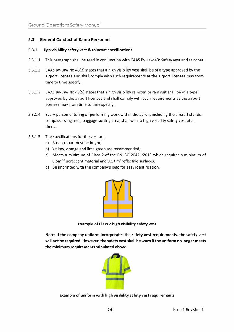
5.3.1.5 The specifications for the vest are:
a) Basic colour must be bright;
b) Yellow, orange and lime green are recommended;
c) Meets a minimum of Class 2 of the EN ISO 20471:2013 which requires a minimum of
0.5m2 fluorescent material and 0.13 m2 reflective surfaces;
d) Be imprinted with the company’s logo for easy identification.
Example of Class 2 high visibility safety vest
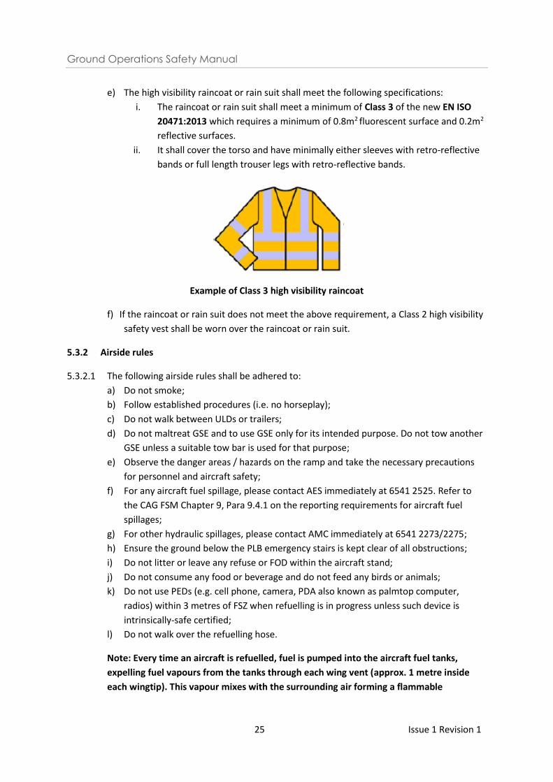
Note: If the company uniform incorporates the safety vest requirements, the safety vest
will not be required. However, the safety vest shall be worn if the uniform no longer meets
the minimum requirements stipulated above.
Example of uniform with high visibility safety vest requirements
Ground Operations Safety Manual
25 Issue 1 Revision 1
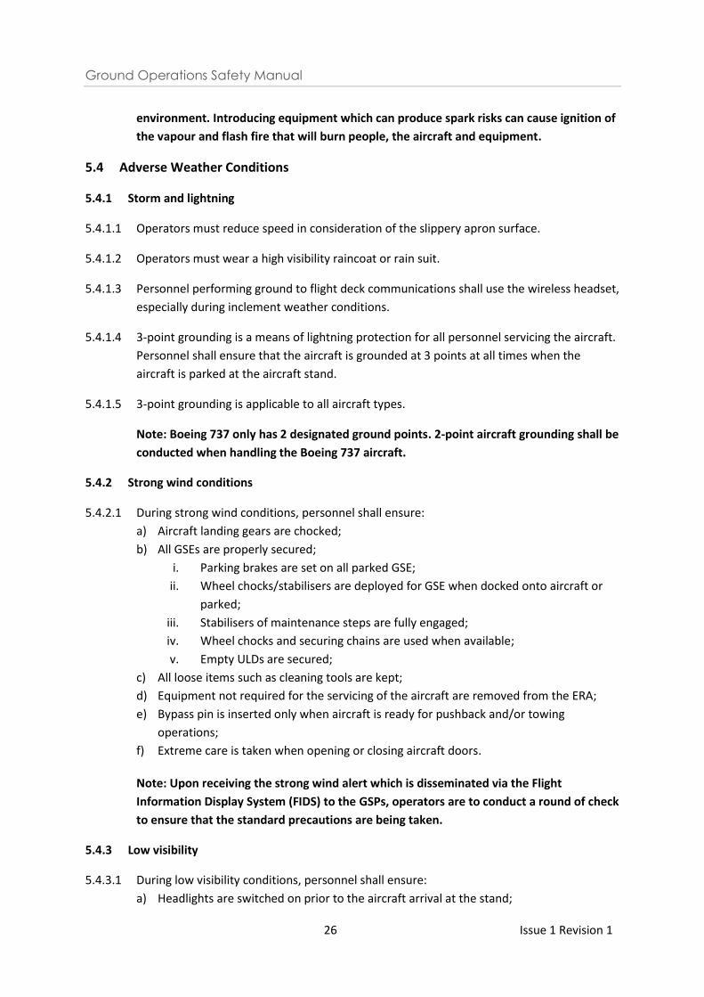
e) The high visibility raincoat or rain suit shall meet the following specifications:
i. The raincoat or rain suit shall meet a minimum of Class 3 of the new EN ISO
20471:2013 which requires a minimum of 0.8m2 fluorescent surface and 0.2m2
reflective surfaces.
ii. It shall cover the torso and have minimally either sleeves with retro-reflective
bands or full length trouser legs with retro-reflective bands.
Example of Class 3 high visibility raincoat
f) If the raincoat or rain suit does not meet the above requirement, a Class 2 high visibility
safety vest shall be worn over the raincoat or rain suit.
5.3.2 Airside rules
5.3.2.1 The following airside rules shall be adhered to:
a) Do not smoke;
b) Follow established procedures (i.e. no horseplay);
c) Do not walk between ULDs or trailers;
d) Do not maltreat GSE and to use GSE only for its intended purpose. Do not tow another
GSE unless a suitable tow bar is used for that purpose;
e) Observe the danger areas / hazards on the ramp and take the necessary precautions
for personnel and aircraft safety;
f) For any aircraft fuel spillage, please contact AES immediately at 6541 2525. Refer to
the CAG FSM Chapter 9, Para 9.4.1 on the reporting requirements for aircraft fuel
spillages;
g) For other hydraulic spillages, please contact AMC immediately at 6541 2273/2275;
h) Ensure the ground below the PLB emergency stairs is kept clear of all obstructions;
i) Do not litter or leave any refuse or FOD within the aircraft stand;
j) Do not consume any food or beverage and do not feed any birds or animals;
k) Do not use PEDs (e.g. cell phone, camera, PDA also known as palmtop computer,
radios) within 3 metres of FSZ when refuelling is in progress unless such device is
intrinsically-safe certified;
l) Do not walk over the refuelling hose.
Note: Every time an aircraft is refuelled, fuel is pumped into the aircraft fuel tanks,
expelling fuel vapours from the tanks through each wing vent (approx. 1 metre inside
each wingtip). This vapour mixes with the surrounding air forming a flammable
Ground Operations Safety Manual
26 Issue 1 Revision 1
environment. Introducing equipment which can produce spark risks can cause ignition of
the vapour and flash fire that will burn people, the aircraft and equipment.
5.4 Adverse Weather Conditions
5.4.1 Storm and lightning
5.4.1.1 Operators must reduce speed in consideration of the slippery apron surface.
5.4.1.2 Operators must wear a high visibility raincoat or rain suit.
5.4.1.3 Personnel performing ground to flight deck communications shall use the wireless headset,
especially during inclement weather conditions.
5.4.1.4 3-point grounding is a means of lightning protection for all personnel servicing the aircraft.
Personnel shall ensure that the aircraft is grounded at 3 points at all times when the
aircraft is parked at the aircraft stand.
5.4.1.5 3-point grounding is applicable to all aircraft types.
Note: Boeing 737 only has 2 designated ground points. 2-point aircraft grounding shall be
conducted when handling the Boeing 737 aircraft.
5.4.2 Strong wind conditions
5.4.2.1 During strong wind conditions, personnel shall ensure:
a) Aircraft landing gears are chocked;
b) All GSEs are properly secured;
i. Parking brakes are set on all parked GSE;
ii. Wheel chocks/stabilisers are deployed for GSE when docked onto aircraft or
parked;
iii. Stabilisers of maintenance steps are fully engaged;
iv. Wheel chocks and securing chains are used when available;
v. Empty ULDs are secured;
c) All loose items such as cleaning tools are kept;
d) Equipment not required for the servicing of the aircraft are removed from the ERA;
e) Bypass pin is inserted only when aircraft is ready for pushback and/or towing
operations;
f) Extreme care is taken when opening or closing aircraft doors.
Note: Upon receiving the strong wind alert which is disseminated via the Flight
Information Display System (FIDS) to the GSPs, operators are to conduct a round of check
to ensure that the standard precautions are being taken.
5.4.3 Low visibility
5.4.3.1 During low visibility conditions, personnel shall ensure:
a) Headlights are switched on prior to the aircraft arrival at the stand;
Ground Operations Safety Manual
27 Issue 1 Revision 1
b) Second level floodlights are switched on (if required);
c) Cautious driving.
5.5 Use of Aircraft Wheel Chocks and Safety Cones
5.5.1 Use of aircraft wheel chocks
5.5.1.1 Sufficient numbers of serviceable chocks shall be provided for the arrival aircraft,
considering the ramp and / or weather conditions.
5.5.1.2 Do not approach the aircraft until:
a) Aircraft is at a complete stop;
b) Engines are switched off and spooling down;
c) Anti-collision lights are switched off;
d) Wheel chocks are positioned;
e) Grounding cables are connected on the nose and main landing gears;
f) Ground/flight crew communication is established, and headset man gives the ‘thumbs
up’ signal.
5.5.2 Placement of wheel chocks
5.5.2.1 Chocks shall be placed in accordance with airline requirements:
a) Walk towards the main gear in the path parallel to the fuselage, avoiding engine intake
areas;
b) Remove any temporarily-placed nose gear chocks, if applicable;
c) When placing chocks, stand well clear of the path of the tires. Approach/leave the
main landing gear from the front or rear;
d) Notify the flight deck when the chocks are placed.
5.5.3 Removal of wheel chocks
5.5.3.1 Remove chocks together with grounding cables when:
a) After loading GSE have been disconnected from the aircraft including the PLB;
b) Airtug is connected to the aircraft;
c) Airtug parking brake is engaged;
d) Aircraft parking brake is engaged.
*To note: Start the disconnection of the grounding cables from the aircraft grounding
point before proceeding to the earth receptacle point.
* To note: Grounding cable and chocks at nose landing gear may be removed earlier to
facilitate the connection of towbarless air tug.
Ground Operations Safety Manual
28 Issue 1 Revision 1
5.5.3.2 When not in use, all unused chocks shall be removed from the aircraft stand and stowed
away in their designated stowage areas.
5.5.4 Use of safety cones
5.5.4.1 Safety cones are a caution indicator for operators to maintain a safety distance from
certain parts of the aircraft to prevent collision by GSE.
5.5.4.2 Safety cones shall be orange in colour with reflective stripes. Cones shall not be used if it
does not serve its intended purpose.
5.5.4.3 Prior to arrival of the aircraft, there shall be sufficient serviceable safety cones for the
aircraft type to be handled.
5.5.5 Placement of safety cones
5.5.5.1 Do not approach the aircraft until:
a) Aircraft is at a complete stop;
b) Engines are switched off and spooling down;
c) Anti-collision lights are switched off;
d) Wheel chocks are positioned;
e) Grounding cables are connected on the nose and main landing gears;
f) Ground / Flight crew communication is established, and headset man gives the
‘thumbs up’ signal.
Note: GSE to approach aircraft when safety cones are in position.
5.5.5.2 Cone placement should be done according with the airlines’ requirement or as
recommended by IATA (IGOM Chapter 4.3), shown in Figure 1 and Figure 2 – within a
maximum of 1 metre outward from the point of the aircraft being protected.
5.5.5.3 It is mandatory to place a safety cone under the tail of aircraft upon aircraft arrival (after
thumbs-up) along with other current safety cones as recommended by IATA or as required
by airlines.
Ground Operations Safety Manual
29 Issue 1 Revision 1
Figure 1: Cone Placement for Wing-Mounted Twin Engine Jet Aircraft.
Ground Operations Safety Manual
30 Issue 1 Revision 1
Figure 2: Cone Placement for Wing-Mounted Four Engine Jet Aircraft (to insert tail cone)
Ground Operations Safety Manual
31 Issue 1 Revision 1
5.5.6 Removal of safety cones
a) Do not remove until GSE and vehicular activities around the aircraft have ceased prior to
departure of the aircraft (excluding the PLB);
b) When not in use, the safety cones shall be placed at the designated storage area.
5.6 Foreign Object Debris
5.6.1 General term for FOD
5.6.1.1 Foreign Object Debris (FOD) is a general term which applies to all loose objects which
endanger the safety of aircraft and therefore must not be left in any area where they
would constitute a hazard.
5.6.1.2 Every individual has a responsibility to ensure that the risk of damage to aircraft from FOD
is minimized.
5.6.1.3 All FOD must be removed and properly disposed of as soon as it is discovered.
5.6.1.4 Often the presence of FOD is due to the carelessness of personnel working in the airside or
the failure to appropriately dispose waste from the airside. FOD are commonly left in
aircraft movement areas by airside personnel or blown to aircraft movement areas from
other airside areas.
Examples of FOD:
Plastic and paper, sheets, rags, wood, metal nuts and bolts, tools and equipment, stones,
pebbles, luggage parts etc.
5.6.1.5 All personnel are responsible for identifying and removing FOD. “If you see it (FOD),
remove it”.
Ground Operations Safety Manual
32 Issue 1 Revision 1
5.6.2 CAG FOD management policy
5.6.2.1 FOD prevention is the duty and responsibility of everyone working in the airside in Changi
Airport. This policy applies to all staff and airside agencies at Changi Airport.
5.6.2.2 All airside partners and personnel are responsible for managing waste generated by their
operations and ensure that the airside areas they use are left in a state of cleanliness no
worse than prior to their use.
5.6.2.3 If anyone witnesses any FOD safety risks, please report them to ACC at 6603 4906.
5.6.3 Results of FOD
5.6.3.1 Foreign object debris may be ingested into aircraft engines, causing damage to critical
engine parts. This is especially hazardous if it occurs in flight, particularly during the take-
off phase.
5.6.3.2 In addition, FOD can cause damage to the tyres, undercarriage, control systems and other
parts of the airframe. All such damage could lead to inflight failures.
5.6.3.3 Items such as rags and wireless headset unit, associated with engineering and servicing of
aircraft, have been left in wheel bays and other ledges where they can subsequently fall
out during take-off phase and create a hazard to subsequent aircraft landing or taking off
on the runway.
5.6.3.4 Failure to maintain ground support equipment (i.e. where parts break off or fall can also
cause FOD).
5.6.4 FOD checks
5.6.4.1 Prior to any aircraft movement at the aircraft stand, the arrival or departure Overall In-
Charge (OIC) shall conduct the FOD walk according to the diagram below.
Ground Operations Safety Manual
33 Issue 1 Revision 1
5.6.4.2 The OIC shall walk the path around the entire boundary of the ERA, including overlapping
ERA, and the adjacent Keep Clear Zone to ensure that these areas are free of equipment,
personnel, FOD and spillage. (See black foot prints in the above diagram)
5.6.4.3 The OIC shall also walk the path along the centreline of the aircraft stand to look out for
any small metal objects or FOD that could damage the aircraft tyres. The OIC shall ensure
that the path and area that the aircraft is moving are free of FOD. (See blue foot prints in
the above diagram)
5.6.4.4 Any FOD found at the aircraft stand shall be properly disposed in the FOD bin provided at
every aircraft stand.
5.6.4.5 Personnel shall perform the following when operating GSE on the ramp:
a) Conduct routine checks on ground equipment (including floors of enclosed cabins);
b) In ramp areas ensure that anything carried in or on a vehicle is secured. Items such as
safety cones and/or wheel chocks should not be left unsecured on GSEs when in
operations.
5.6.4.6 All items that are generated as part of aircraft handling (especially baggage items such as
locks and zippers and cargo loads that may have fallen off their containers) are cleared
from the apron area; and
5.6.4.7 Area that the aircraft is moving towards is clear of FOD to ensure safe aircraft movement.
5.6.5 Engine start
5.6.5.1 Qualified personnel should complete a final examination of the aircraft before engine start
to confirm:
a) Surface condition of the apron is adequate to conduct operations; and
b) Apron is clear of items that might cause FOD.
Ground Operations Safety Manual
34 Issue 1 Revision 1
5.6.6 Actions by Airline’s Agent during refuelling with passengers on board
5.6.6.1 Personnel shall ensure the escape routes of passengers on board such as passenger stairs
and bridges are clear of FOD.
5.6.7 What to do when carrying out regular activities at the airside
5.6.7.1 Remove all items (including trash) generated from aircraft servicing from the aircraft stand
immediately, unless with prior approval from CAG.
5.6.7.2 Always return all equipment to their designated positions after use. These include safety
cones, aircraft wheel chocks, aircraft grounding cables and fire extinguishers.
5.6.7.3 Do not leave any personal belongings unattended anywhere, especially on the plinth area.
Ensure that personal belongings carried on the person are well kept and secured and do
not fall off onto airside areas.

Ground Operations Safety Manual
35 Issue 1 Revision 1
6 Standard Operating Procedures
6.1 Introduction
6.1.1 Standard Operating Procedures (SOPs) are the foundation of effective personnel
coordination and a key component in team resource management and threat and error
management.
6.1.2 GSPs shall establish and maintain SOPs for their various operations accordingly, and to
ensure that they can be carried out effectively and safely.
6.1.3 The SOPs must be aligned to the operating procedures stated in the GOSM.
6.1.4 GSPs shall ensure that all personnel are trained in the relevant SOPs to maintain a
standardised level of currency.
6.1.5 The SOPs shall be reviewed whenever there is a change to the operation.
6.2 Standardized Ramp Handling Procedure for Aircraft Arrival and Departure
6.2.1 The standardised arrival and departure handling procedure was developed in collaboration
with the Changi airside community. This standardised procedure seeks to improve ground
operational safety by specifying the minimum standard operating requirements for ramp
handling, and to reduce the complexity of ground handling operation by harmonising
multiple stakeholders performing ground handling functions on the same aircraft.
Ground Operations Safety Manual
36 Issue 1 Revision 1
6.3 Arrival OIC Roles and Responsibilities
6.3.1 The ADGS operator/ manual marshaller is recognized as the overall-in-charge for arrival
phase of ground handling. He is empowered to point out any violation which could
compromise safety and demand for violation to be corrected.
Note: The OIC shall contact AMC if operators do not comply with safety procedures.
6.3.2 The key safety responsibilities of the arrival OIC include the following:
a) Ensure that the ERA and the adjacent keep clear zones are free of FOD, equipment
and/or spillage;
b) Ensure that the ADGS is operating and displaying the correct aircraft type;
c) Ensure that the PLB is fully retracted in its “parked position” or at the “pre-position”;
d) Ensure all ground service equipment (GSE) and personnel are positioned outside of the
ERA and the adjacent keep clear zones prior to aircraft arrival;
e) Ensure all personnel stay clear of the ERA until the nose wheels are chocked, grounded,
anti-collision lights have been switched off and thumbs-up given.
6.3.3 Details of the standardized arrival procedure
6.3.3.1 Pre-Arrival
Step Action by Duties
1 ADGS Operator Place two safety cones with a safety pole on them at the
front of the ERA before conducting the FOD check
Example of how the safety cones and pole shall be placed
a) No GSE & personnel are allowed inside the ERA and
“Keep Clear” zone.
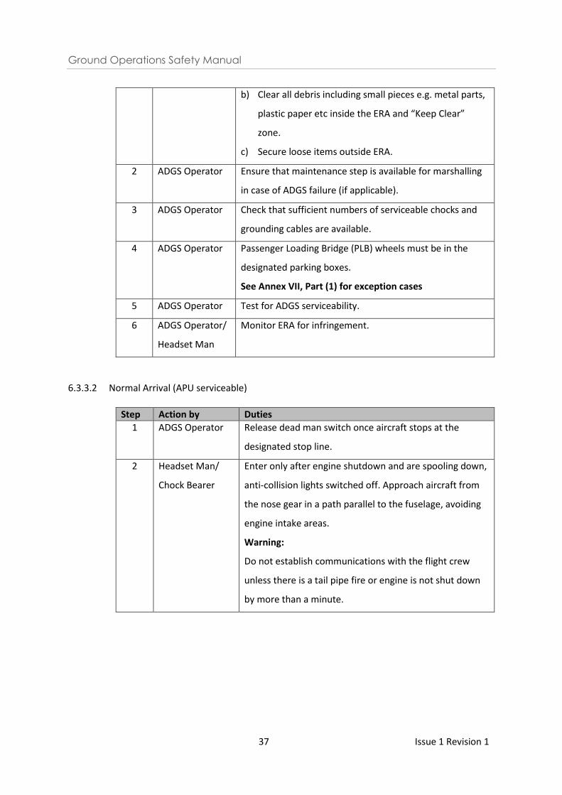
Ground Operations Safety Manual
37 Issue 1 Revision 1
b) Clear all debris including small pieces e.g. metal parts,
plastic paper etc inside the ERA and “Keep Clear”
zone.
c) Secure loose items outside ERA.
2 ADGS Operator Ensure that maintenance step is available for marshalling
in case of ADGS failure (if applicable).
3 ADGS Operator Check that sufficient numbers of serviceable chocks and
grounding cables are available.
4 ADGS Operator Passenger Loading Bridge (PLB) wheels must be in the
designated parking boxes.
See Annex VII, Part (1) for exception cases
5 ADGS Operator Test for ADGS serviceability.
6 ADGS Operator/
Headset Man
Monitor ERA for infringement.
6.3.3.2 Normal Arrival (APU serviceable)
Step Action by Duties
1 ADGS Operator Release dead man switch once aircraft stops at the
designated stop line.
2 Headset Man/
Chock Bearer
Enter only after engine shutdown and are spooling down,
anti-collision lights switched off. Approach aircraft from
the nose gear in a path parallel to the fuselage, avoiding
engine intake areas.
Warning:
Do not establish communications with the flight crew
unless there is a tail pipe fire or engine is not shut down
by more than a minute.
Ground Operations Safety Manual
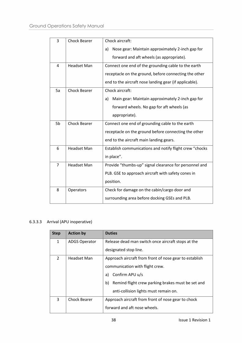
38 Issue 1 Revision 1
3 Chock Bearer Chock aircraft:
a) Nose gear: Maintain approximately 2-inch gap for
forward and aft wheels (as appropriate).
4 Headset Man Connect one end of the grounding cable to the earth
receptacle on the ground, before connecting the other
end to the aircraft nose landing gear (if applicable).
5a Chock Bearer Chock aircraft:
a) Main gear: Maintain approximately 2-inch gap for
forward wheels. No gap for aft wheels (as
appropriate).
5b Chock Bearer Connect one end of grounding cable to the earth
receptacle on the ground before connecting the other
end to the aircraft main landing gears.
6 Headset Man Establish communications and notify flight crew “chocks
in place”.
7 Headset Man Provide “thumbs-up” signal clearance for personnel and
PLB. GSE to approach aircraft with safety cones in
position.
8 Operators Check for damage on the cabin/cargo door and
surrounding area before docking GSEs and PLB.
6.3.3.3 Arrival (APU inoperative)
Step Action by Duties
1 ADGS Operator Release dead man switch once aircraft stops at the
designated stop line.
2 Headset Man Approach aircraft from front of nose gear to establish
communication with flight crew.
a) Confirm APU u/s
b) Remind flight crew parking brakes must be set and
anti-collision lights must remain on.
3 Chock Bearer Approach aircraft from front of nose gear to chock
forward and aft nose wheels.
Ground Operations Safety Manual
39 Issue 1 Revision 1
Warning:
Do not chock main gear yet.
4 Headset Man Connect one end of the grounding cable to the earth
receptacle on the ground before connecting the other
end to the aircraft nose landing gear (if applicable).
5 Headset Man Obtain clearance from flight crew to connect GPU.
Warning:
To avoid distraction, do not assist with GPU connection.
6 Headset Man/
Chock Bearer
Engines must be shut down and anti-collision lights
switched off before signalling the chock bearer to chock
and ground the main landing gears.
7a Chock Bearer Chock aircraft:
Main gear: Maintain approximately 2-inch gap for
forward wheels. No gap for aft wheels (as appropriate).
7b Chock Bearer Connect one end of the grounding cable to the earth
receptacle on the ground before connecting the other
end to the aircraft main landing gear.
8 Headset Man Establish communications and notify the flight crew
“chocks in place”.
9 Headset Man Provide “thumbs-up” signal clearance for personnel and
PLB. GSE to approach aircraft with safety cones in
position.
10 Operators Check for damage on the cabin/cargo door and
surrounding area before docking GSEs and PLB.
6.4 Departure OIC Roles and Responsibilities
6.4.1 The headset operator is recognized as the overall-in-charge for the departure phase of
ground handling. He is empowered to point out any violation which could compromise
safety and demand for violation to be corrected.
Note: The OIC shall contact AMC if operators do not comply with safety procedures.
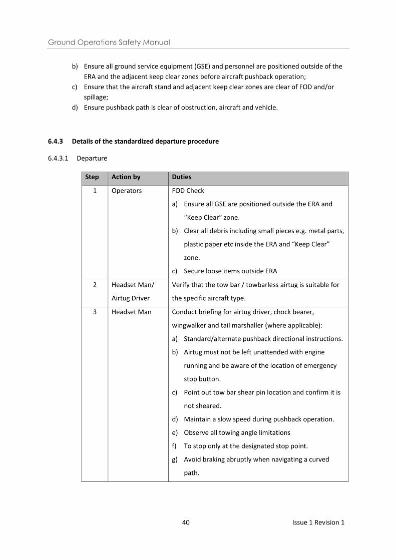
6.4.2 The key safety responsibilities of the departure OIC include the following:
a) Ensure that the PLB is fully retracted in its “parked position” or at the “pre-position”;
Ground Operations Safety Manual
40 Issue 1 Revision 1
b) Ensure all ground service equipment (GSE) and personnel are positioned outside of the
ERA and the adjacent keep clear zones before aircraft pushback operation;
c) Ensure that the aircraft stand and adjacent keep clear zones are clear of FOD and/or
spillage;
d) Ensure pushback path is clear of obstruction, aircraft and vehicle.
6.4.3 Details of the standardized departure procedure
6.4.3.1 Departure
Step Action by Duties
1 Operators FOD Check
a) Ensure all GSE are positioned outside the ERA and
“Keep Clear” zone.
b) Clear all debris including small pieces e.g. metal parts,
plastic paper etc inside the ERA and “Keep Clear”
zone.
c) Secure loose items outside ERA
2 Headset Man/
Airtug Driver
Verify that the tow bar / towbarless airtug is suitable for
the specific aircraft type.
3 Headset Man Conduct briefing for airtug driver, chock bearer,
wingwalker and tail marshaller (where applicable):
a) Standard/alternate pushback directional instructions.
b) Airtug must not be left unattended with engine
running and be aware of the location of emergency
stop button.
c) Point out tow bar shear pin location and confirm it is
not sheared.
d) Maintain a slow speed during pushback operation.
e) Observe all towing angle limitations
f) To stop only at the designated stop point.
g) Avoid braking abruptly when navigating a curved
path.
Ground Operations Safety Manual
41 Issue 1 Revision 1
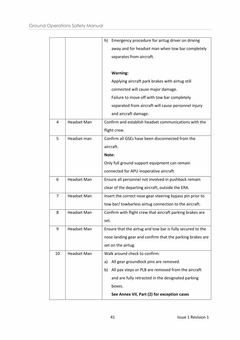
h) Emergency procedure for airtug driver on driving
away and for headset man when tow bar completely
separates from aircraft.
Warning:
Applying aircraft park brakes with airtug still
connected will cause major damage.
Failure to move off with tow bar completely
separated from aircraft will cause personnel injury
and aircraft damage.
4 Headset Man Confirm and establish headset communications with the
flight crew.
5 Headset man Confirm all GSEs have been disconnected from the
aircraft.
Note:
Only full ground support equipment can remain
connected for APU inoperative aircraft.
6 Headset Man Ensure all personnel not involved in pushback remain
clear of the departing aircraft, outside the ERA.
7 Headset Man Insert the correct nose gear steering bypass pin prior to
tow bar/ towbarless airtug connection to the aircraft.
8 Headset Man Confirm with flight crew that aircraft parking brakes are
set.
9 Headset Man Ensure that the airtug and tow bar is fully secured to the
nose landing gear and confirm that the parking brakes are
set on the airtug.
10 Headset Man Walk around check to confirm:
a) All gear groundlock pins are removed.
b) All pax steps or PLB are removed from the aircraft
and are fully retracted in the designated parking
boxes.
See Annex VII, Part (2) for exception cases
Ground Operations Safety Manual
42 Issue 1 Revision 1
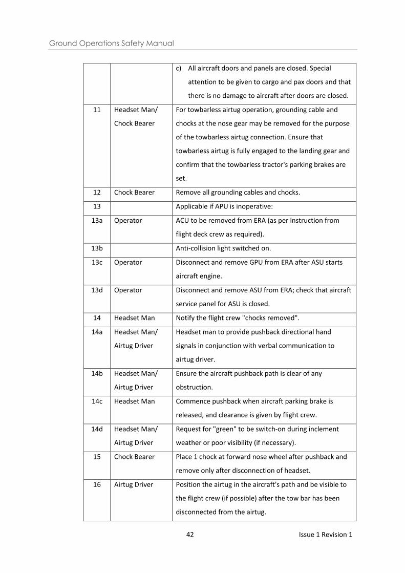
c) All aircraft doors and panels are closed. Special
attention to be given to cargo and pax doors and that
there is no damage to aircraft after doors are closed.
11 Headset Man/
Chock Bearer
For towbarless airtug operation, grounding cable and
chocks at the nose gear may be removed for the purpose
of the towbarless airtug connection. Ensure that
towbarless airtug is fully engaged to the landing gear and
confirm that the towbarless tractor's parking brakes are
set.
12 Chock Bearer Remove all grounding cables and chocks.
13 Applicable if APU is inoperative:
13a Operator ACU to be removed from ERA (as per instruction from
flight deck crew as required).
13b Anti-collision light switched on.
13c Operator Disconnect and remove GPU from ERA after ASU starts
aircraft engine.
13d Operator Disconnect and remove ASU from ERA; check that aircraft
service panel for ASU is closed.
14 Headset Man Notify the flight crew "chocks removed".
14a Headset Man/
Airtug Driver
Headset man to provide pushback directional hand
signals in conjunction with verbal communication to
airtug driver.
14b Headset Man/
Airtug Driver
Ensure the aircraft pushback path is clear of any
obstruction.
14c Headset Man Commence pushback when aircraft parking brake is
released, and clearance is given by flight crew.
14d Headset Man/
Airtug Driver
Request for "green" to be switch-on during inclement
weather or poor visibility (if necessary).
15 Chock Bearer Place 1 chock at forward nose wheel after pushback and
remove only after disconnection of headset.
16 Airtug Driver Position the airtug in the aircraft's path and be visible to
the flight crew (if possible) after the tow bar has been
disconnected from the airtug.
Ground Operations Safety Manual
43 Issue 1 Revision 1
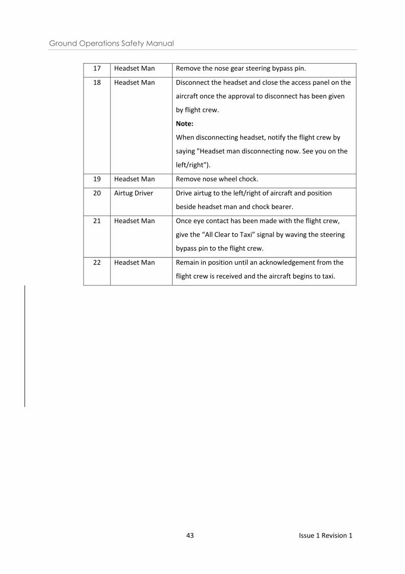
17 Headset Man Remove the nose gear steering bypass pin.
18 Headset Man Disconnect the headset and close the access panel on the
aircraft once the approval to disconnect has been given
by flight crew.
Note:
When disconnecting headset, notify the flight crew by
saying "Headset man disconnecting now. See you on the
left/right").
19 Headset Man Remove nose wheel chock.
20 Airtug Driver Drive airtug to the left/right of aircraft and position
beside headset man and chock bearer.
21 Headset Man Once eye contact has been made with the flight crew,
give the “All Clear to Taxi” signal by waving the steering
bypass pin to the flight crew.
22 Headset Man Remain in position until an acknowledgement from the
flight crew is received and the aircraft begins to taxi.
Ground Operations Safety Manual
44 Issue 1 Revision 1
7 Aircraft Docking Guidance System/ Manual Marshalling
7.1 Pre-arrival Handling
a) Arrive at the aircraft stand at least 15 minutes prior to aircraft’s ETA;
b) Conduct a serviceability check on the ADGS at least 15 minutes prior to aircraft ETA;
c) Be aware of the aircraft type assigned to the stand and press the ‘confirm’ button on the
ADGS control panel;*
d) Upon arrival at the stand, check that all equipment is properly secured and positioned in
the ESA. The surrounding area must be free from any FOD and the stand must clear of oil /
fluid / fuel spillage;
e) The ERA must be clear of personnel and equipment. Maintain a constant lookout of the
ERA and refrain from using mobile devices unnecessarily;
f) Conduct the FOD walk and cover the ERA boundary and adjacent keep clear zones.
g) Ensure sufficient serviceable wheel chocks and safety cones are provided;
h) Manual marshallers shall stand by with marshalling bats or ‘Dayglo’ wands (to be
illuminated in low visibility / night operations) and marshalling platforms (if required) in
the event that manual marshalling is required;
i) The space fronting aircraft stands, either “No Parking Area” or holding strip, may be used
to perform manual marshalling;
j) The ADGS operator is highly recommended to perform a second FOD walk at five minutes
before the aircraft’s ETA;
k) The PLB shall be fully retracted and parked at its designated parking box.
See Annex VII, Part (1) for exception cases
* A chock may be positioned at least 1 metre away from the edge of the designated stop line to serve as a guidance marker for aircraft nose wheel stop position.
7.2 Arrival Handling
a) Inform FMC immediately if the ADGS is faulty;
b) In the event where the ADGS is not available, perform manual marshalling using the
correct marshalling signals before aircraft reaches the stand lead-in line (refer to Annex II
for aircraft marshalling signals);
c) Do not guide any aircraft for other aircraft stands other than the assigned one;
d) Guide only the assigned aircraft type and airline at the aircraft stand a complete stop at
the designated aircraft type stop line;
Note: In the event that an incorrect airline or aircraft type attempts to enter the aircraft
stand, release the deadman switch immediately to stop the aircraft from turning or
taxiing further into the aircraft stand. Contact the company’s control room for the next
course of action to be taken.
e) The ERA must be clear of any obstruction;
Ground Operations Safety Manual
45 Issue 1 Revision 1
f) If the aircraft overshoots / undershoots the designated stop line by more than 0.5 metres
(approximately the length of 2 feet, personnel shall arrange for an airtug to reposition the
aircraft;
g) After the aircraft comes to a complete stop with its engines shut down and anti-collision
lights OFF, personnel can then proceed to place chocks and grounding cables on the
aircraft;
h) If at any time during aircraft movement the ADGS operator / manual marshaller is unsure
or identifies an imminent danger, STOP the aircraft by giving the ‘STOP’ signal with the use
of wands or by releasing the deadman switch on the ADGS control panel;
8 Operation of Passenger Loading Bridge
8.1 Pre-arrival Handling
a) Arrive at the stand at least 15 minutes prior to aircraft’s ETA;
b) Ensure that no FOD, GSE or any obstacles are within the red hatched area beneath the PLB
and in the surrounding area of the parking stand;
c) Ensure that the PLB is fully retracted and parked at its designated parking box;
See Annex VII, Part (1) for exception cases
d) If the wheels of the PLB are extended beyond the designated parking box, inform ADGS
operator NOT to activate ADGS and DO NOT RETRACT THE PLB. Instead, alert FMC and the
PLB maintenance staff will respond;
e) Ensure that the passageway within the PLB is free of FOD prior to aircraft arrival;
f) Ensure that all safety chains (located in the cab, Tunnel ‘A’ and PLB entrance) are secured
and hooked;
g) Conduct a serviceability check of the PLB and check for ‘No Go’ items – If any of the
following is missing, the PLB is considered unserviceable. They are:
i. Emergency stop;
ii. Selector key switch;
iii. Power on button;
iv. Cabin closure (condition and padding);
v. Horizontal drive button;
vi. Vertical drive button;
vii. Cab rotation button;
viii. Closure drive button;
h) In the event where the PLB is unserviceable:
i. Inform CAG FMC immediately;
ii. If the maintenance staff is unable to rectify the PLB fault upon reaching the site,
the PLB operator is to deploy the passenger step for passenger disembarkation
upon instructed by the PLB maintenance staff.
iii. Inform the airside officer / operations supervisor of the incoming flight and
request for a passenger step to be dispatched to the stand;
Ground Operations Safety Manual
46 Issue 1 Revision 1
i) Activate the switches for air conditioning and lighting in the PLB prior to aircraft arrival.
Keep the roller shutter/ bi-fold doors closed until the PLB is docked;
j) Be aware of the incoming aircraft type and position the height of the PLB accordingly;
k) Position the PLB wheels in the wheels positioning box after performing the serviceability
checks;
l) Standby a marshaller to be deployed on Apron ground in the event when PLB
malfunctions. In the event that the Auto-dock function is unserviceable and the PLB
operator must manually dock the PLB to the aircraft, the PLB operator would have to
ensure that a marshaller is positioned on the apron ground to guide him in his docking
operation.
8.2 Arrival Handling
a) Keep the PLB roller shutter/bi-fold doors closed until the PLB is docked;
b) No other personnel shall be present in the cab during docking. All other personnel shall
stand behind the safety chains behind the operator;
c) Commence PLB docking operation only after receiving the thumbs-up signal from the
headset man;
d) Check the aircraft fuselage for any damage before proceeding to dock the PLB. If any
damage is spotted, do not dock the PLB towards the aircraft. Inform CAG AMC
immediately;
e) For safety concerns, conduct visual inspections of the apron operation area through the
CCTV screen while operating the PLB. In the event where the auto-dock function is
unserviceable and the PLB operator must manually dock the PLB to the aircraft, ensure
that a marshaller is positioned on the apron ground to guide him in his docking
operations;
f) In the event the PLB operates abnormally during auto-dock mode, release the auto-dock
button immediately to abort operation. If the PLB does not stop immediately and
continues moving, press the red emergency button to cease all electrical supply to the PLB
immediately;
g) Stop the PLB 0.5 metres from the aircraft to make final adjustments before docking;
h) Activate the auto-leveller after docking to the aircraft. (The auto-leveller is to be engaged
prior to opening the aircraft door);
i) Adjust and maintain the height between the PLB cab floor and the aircraft door sill based
on the height indicated by the height indicator located on the right of the bumper;
j) For A380 aircraft, ensure that the correct docking sequence is executed (i.e. L1 / L3 / L2);
k) Ensure that the cabin closure is extended towards the aircraft door;
l) After all checking sequence is completed and the “auto-leveller” has been activated,
remove the key from the operation console;
m) Unhook the safety chains located in the cab and Tunnel ‘A’;
n) Remain within the audible range of the warning buzzer and horn regardless with or
without disembarkation of the passengers.
Ground Operations Safety Manual
47 Issue 1 Revision 1
Note: For A380 aircraft, the docking of the PLB L2 arm is to be done only after the PLB L1
arm and PLB L3 arm has been docked to the aircraft.
8.3 Departure Handling
a) Ensure that a marshaller is deployed on apron ground to assist with the PLB retraction;
b) Perform a check to ensure that no FOD, GSE or any obstacles are within the red hatched
area beneath the PLB and in the surrounding area of the parking stand prior to operating
the PLB;
c) Check the fuselage of the aircraft for any damage before proceeding to retract the PLB
from the aircraft. If any damage is spotted, do not retract the PLB. Inform CAG AMC
immediately;
d) Ensure that all safety chains are hooked up and secured prior to retracting the PLB;
e) Ensure that the aircraft door is completely closed prior to disengaging the auto-leveller
and retracting the canopy;
f) Conduct clearance checks and ensure that the marshaller is present before the bridge is
retracted;
g) Ensure weather closure is retracted before retracting the PLB;
h) Ensure that the PLB roller shutter/bi-fold doors are closed before retracting the PLB
i) Applicable to PLB Auto Mode: PLB operator retracts 0.5 metres manually before setting to
Auto park function;
j) Applicable to PLB Manual Mode: PLB operator withdraws the PLB according to the
marshaller guidance;
k) Retract the PLB to the designated parking box position before the start of pushback.
See Annex VII, Part (2) for exception cases
Note: For A380 aircraft, the PLB L2 arm is to be retracted first before retracting the PLB
L1 arm and the PLB L3 arm.
l) Set the PLB to the default height;
m) Turn the keys to ‘OFF’ position and remove from the instrument console;
n) Ensure the emergency button is depressed;
o) Remain on the bridge until the aircraft is pushed back;
p) Clear all debris on the passageway.
q) Ensure that the PLB wheels are parked within the designated parking boxes;
r) In the event the PLB operates abnormally during auto-dock mode, release the auto-dock
button immediately to abort operation and to stop the PLB;
s) In the event where the PLB is unable to be retracted from the departing aircraft, inform
FMC;
t) Prior to towing the PLB, the PLB operator (in the presence of the CAG PLB maintenance
contractor) shall ascertain that:
i. The aircraft cabin door is shut;
ii. No passengers are in the PLB.
iii. Airline representative is informed;
iv. Seek the assistance of a tractor driver to tow the PLB.
Ground Operations Safety Manual
48 Issue 1 Revision 1
9 Operation of Ground Support Equipment Associated with Aircraft
Handling and Loading
9.1 Introduction
9.1.1 All self-propelled GSE interfacing with the aircraft should have an aircraft proximity system
facility.
9.2 General Safety Instructions
9.2.1 Basic operating requirements for GSE
a) All motorised GSE shall be issued with a valid CAG’s AVP and equipped with a valid fire
extinguisher. The validity of the fire extinguisher must be clearly displayed on the
extinguisher.
b) Check equipment prior to initial use (with reference to 9.3.1, 9.3.2 or 9.3.3)
c) Do not drive GSE with lifting devices in the raised position, except for final positioning
onto the aircraft;
d) Do not operate the platform while in motion;
e) All GSE shall not touch the aircraft. When positioning GSE, a safety clearance must be
maintained between the GSE and the aircraft;
f) All safety rails must be fully retracted/lowered during positioning;
g) Do not leave any vehicle unattended with its engine running.
Note: GPUs and ACUs may be left running unattended with its engine running.
h) Do not use faulty GSE;
i) Do not transport wheel chocks and / or safety cones placed on the roof top of GSE such
as tractors and covered trolleys. Top of containers shall be free of baggage / cargo /
mail;
j) When handling smaller aircraft such as A320 and B737 etc (i.e. Code A to C), do not tow
more than 2 baggage trolleys / carts and dollies within the ERA for positioning for
unloading / loading of baggage / cargo purposes;
k) Deploy stabilizers and parking brakes when GSE is stationary.
9.2.2 Driving and parking in ERA
a) Do not drive GSE faster than walking speed;
b) Make two safety stops;
i. One complete stop prior to entering the ERA;
ii. One complete stop as a brake check, at no less than 5 metres from the aircraft.
c) GSE travelling along a parked aircraft must keep at least 1 metre away. Reference point
shall be used to gauge the minimum safety distance. Safety cones placed along various
parts of the aircraft (maximum 1 metre away from the aircraft) are examples of
reference points for drivers.
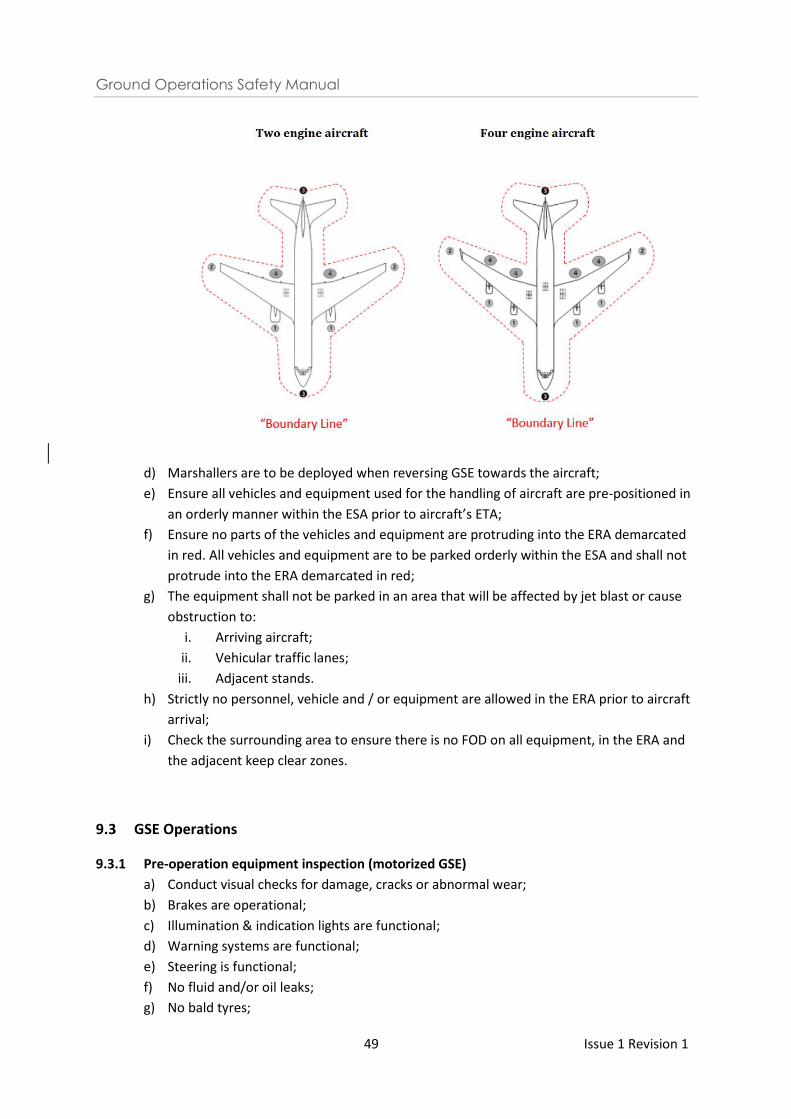
Ground Operations Safety Manual
49 Issue 1 Revision 1
d) Marshallers are to be deployed when reversing GSE towards the aircraft;
e) Ensure all vehicles and equipment used for the handling of aircraft are pre-positioned in
an orderly manner within the ESA prior to aircraft’s ETA;
f) Ensure no parts of the vehicles and equipment are protruding into the ERA demarcated
in red. All vehicles and equipment are to be parked orderly within the ESA and shall not
protrude into the ERA demarcated in red;
g) The equipment shall not be parked in an area that will be affected by jet blast or cause
obstruction to:
i. Arriving aircraft;
ii. Vehicular traffic lanes;
iii. Adjacent stands.
h) Strictly no personnel, vehicle and / or equipment are allowed in the ERA prior to aircraft
arrival;
i) Check the surrounding area to ensure there is no FOD on all equipment, in the ERA and
the adjacent keep clear zones.
9.3 GSE Operations
9.3.1 Pre-operation equipment inspection (motorized GSE)
a) Conduct visual checks for damage, cracks or abnormal wear;
b) Brakes are operational;
c) Illumination & indication lights are functional;
d) Warning systems are functional;
e) Steering is functional;
f) No fluid and/or oil leaks;
g) No bald tyres;
Ground Operations Safety Manual
50 Issue 1 Revision 1
h) Rubber bumpers are in good condition.
Note: Not applicable to refuellers.
9.3.2 Pre-operation equipment inspection (non-motorized GSE)
a) Conduct visual checks for damage, cracks or abnormal wear;
b) Stabilizers and braking mechanisms are functional;
c) No bald tyres.
Note: Not applicable to refuellers.
9.3.3 Pre-operation equipment inspection (applicable to refuellers only)
a) Conduct visual checks for damage, cracks or abnormal wear;
b) Brakes are operational;
c) Illumination & indication lights are functional;
d) No fluid and/or oil leaks;
e) No bald tyres.
9.3.4 Load carried by GSE
a) All load carried by the vehicle shall be secured at all times;
b) The use of plastic sheeting over the top of the load is acceptable however, it shall always
be placed underneath the cargo net and be adequately tucked into the edges of the load
to prevent it from becoming potential FOD during transportation or strong wind
conditions.
9.3.5 Unit Load Devices
a) ULDs refer to baggage and cargo containers. Do not store ULDs on the ground and
always use a suitable ULD base support system;
b) Close and latch doors fully before towing and loading.
9.3.6 Mobile and non-motorized passenger steps/stairs
a) Check the condition of the rubber bumpers before used;
b) Select the height of the aircraft type before docking;
c) Move the equipment only when the movement path is clear.
d) If the passenger steps / stairs are towed (non-motorized equipment), disconnect them
from the tractor and manually position them toward the aircraft;
e) Do not go over the fuelling hoses;
f) Extend side rails after the cabin door has been opened;
g) Close the aircraft cabin door before removing the passenger steps / stairs.
Note: Aircraft cabin door shall not be in open position without any GSE (platform or
PLB) securely positioned at the door.
9.3.7 Belt loader/skyloader
9.3.7.1 When operating the belt loader / skyloader:
a) Check that the rubber bumpers are in good condition before deploying;
Ground Operations Safety Manual
51 Issue 1 Revision 1
b) Position and remove the equipment in a straight line with the cargo hold door at a 90o
angle to the aircraft fuselage till clear of aircraft engine;
c) The rubber bumpers must never make contact with the aircraft. Maintain a safety gap
between the equipment and aircraft at all times when docking;
d) Do not go over the fuelling hoses;
e) Raise / extend the side handrails after the equipment is positioned;
f) Do not sit or stand on the conveyor belt during GSE movement and when the conveyor
belt is in operation (up or down);
g) When placing items on the conveyor belt, ensure they are stable and will not fall off;
h) Do not overload.
i) For a towable skyloader, disconnect them from the tractor first before manually
positioning them towards the aircraft.
9.3.8 ULD Loader/ JCPL/ MDL
9.3.8.1 When operating loading GSEs:
a) Check that the rubber bumpers are in good condition before deploying;
b) Check that the GSE is serviceable before use;
c) Never drive the GSE under the aircraft wings;
d) Do not go over the fuelling hoses;
e) Do not use the JCPL / MDL to transport ULDs across the ramp;
f) When reversing from aircraft, do so in a straight line with the cargo hold door at a 90o
angle to the aircraft fuselage till clear of aircraft engine;
g) Driver to use snail speed when docking and reversing from the aircraft.
h) Maintain a safety gap between the equipment and aircraft when docking.
9.3.9 Elevating equipment
9.3.9.1 When operating elevating equipment:
a) The final position of the GSE must allow for a safe working area while in the raised
position at the aircraft door to prevent personnel and objects from falling;
b) Maintain a safety gap between the equipment and aircraft when docking;
c) Check for any obstructions over both sides of the GSE before lowering;
d) Engage stabilizers and parking brakes when equipment is stationary;
e) Use a guide person when vision is restricted. The guide person shall be in a position to
accurately judge clearances and communicate signals to the driver/operator. Stop
immediately if visual contact with the guide person is lost;
f) Close and secure all doors when servicing is complete.
g) Do not go over the fuelling hoses;
9.3.10 Potable Water Servicing and Toilet Servicing
a) Wear PPE at all times;
b) After servicing, the fitting caps and service panel door must be closed and latched;
Ground Operations Safety Manual
52 Issue 1 Revision 1
c) Report any spillage on the aircraft stand to his supervisor for cleaning arrangement.
d) Do not go over the fuelling hoses;
9.4 Aircraft Ground Stability
a) In general, when loading, load forward holds before aft holds;
b) When offloading, offload aft holds before forward holds;
c) To avoid “tail-tipping” during ground operations, sequential loading / unloading
instructions shall be followed in accordance to airlines’ requirements;
d) Supervision personnel shall observe the aircraft ground stability during ground operations.
e) For cargo aircraft, a tail support stanchion or nose tether may be required to be fitted
during loading and offloading
9.5 Low-wing aircraft (e.g. B737)
a) To prevent damage to low wing aircraft, baggage tractors should stop about 1 metre from
the belt loader / skyloader and unhook the baggage trolleys;
b) Move the tractor away and position the carts;
c) When removing the baggage trolleys, the tractor should be positioned pointing away from
the aircraft wing and the baggage trolley pulled to the tractor;
d) Tractors shall never drive under the aircraft wings.
9.6 Grounding of Aircraft
9.6.1 Introduction
9.6.1.1 It is mandatory to ground the aircraft at three points at all times when the aircraft is
parked at the aircraft stand, as a means of lightning protection for all apron staff servicing
the aircraft.
9.6.1.2 The practice of 3-point aircraft grounding is applicable to all aircraft types, except for
Boeing 737. Boeing 737 only has 2 designated ground points, 2-point aircraft grounding
should be carried out when handling the Boeing 737 aircraft.
9.6.1.3 All airside personnel are to exercise responsibility when using the aircraft grounding
cables, and to always return them to their designated position after use.
9.6.2 Connection of grounding cables
a) Headset man to ensure that grounding cables are connected at the nose and two main
landing gears before proceeding to connect the headset transceiver to establish
communications with the cockpit pilot.
b) When connecting the grounding cable, one should always connects one end of the
grounding cable to the earth receptacle point before connecting the other end to the
aircraft grounding point
Ground Operations Safety Manual
53 Issue 1 Revision 1
9.6.3 Removal of grounding cables
Remove grounding cables together with chocks when:
a) After loading GSE have been disconnected from the aircraft including the PLB
b) Airtug is connected to the aircraft
c) Airtug parking prake is engaged
d) Aircraft parking brake is engaged
*To note: Start the disconnection of the grounding cables from the aircraft grounding
point before proceeding to the earth receptacle point.
*To note: Grounding cables and chocks at nose landing gear may be removed earlier to
facilitate the connection of towbarless air tug.
9.7 Aircraft Departure
9.7.1 Action prior to pushback of aircraft
9.7.1.1 All persons and GSE not involved in the aircraft departure operation are to remain outside
of the ERA; and
9.7.1.2 The ground personnel performing the final check on the aircraft shall check to ensure that
all aircraft servicing panels and / or hatches are closed and latched.
9.7.2 Removal of wheel chocks
9.7.2.1 Remove the chocks only when:
a) After loading GSE have been disconnected from the aircraft including the PLB;
b) Airtug is connected to the aircraft;
c) Airtug parking brake is engaged;
d) Aircraft parking brake is engaged.
e) Do not leave wheel chocks on the ramp. When not in use, stow them in their
designated stowage place at the aircraft stand.
9.7.3 Removal of safety cones
9.7.3.1 Safety cones can be removed with PLB still attached to aircraft. Headset man must be
attentive at this time to avoid any ERA infringement and vehicle failure to give way to
aircraft cases.
Ground Operations Safety Manual
54 Issue 1 Revision 1
10 Aircraft Pushback
10.1 Pre-departure Handling
a) Ensure that the surface condition is safe to conduct the pushback operation i.e. clear of oil
spill and other FOD;
b) Ensure all the aircraft service doors / panels are closed and locked;
c) Only the required equipment and personnel involved are in the ERA;
d) Ensure that the PLB is fully retracted and wheels are parked correctly within the
designated parking boxes.
See Annex VII, Part (2) for exception cases
e) Ensure that the pushback path is clear of obstructions.
10.2 Departure Handling
a) Check pushback procedures of the designated aircraft stand prior to performing pushback.
b) Establish and maintain communication with the flight crew via headset throughout the
whole operation;
c) Remain clear of the hazard zones such as aircraft nose gear, aircraft engines and near the
airtug or tractor;
d) Use standard phraseology for all verbal communication between the flight deck or brake
operator and ground personnel. Provision should be made for a back-up communication
system in the event of a failure of the primary system;
e) Use standard hand signals for manual communications;
f) During the pushback, align the aircraft such that the taxiway centreline is in between the
aircraft main landing gears to provide sufficient wing and tail clearance;
g) If ground crew require guidance to locate the taxiway centreline, inform flight deck crew
to request Changi Tower to switch on the taxiway centreline lights;
h) Spread out the braking process over as long a distance as possible, brake lightly and
progressively while reducing speed as gradually as possible;
i) Avoid abrupt turning of the steering wheel as this can potentially be a skid trigger.
Observe gentle and gradual steering at all times during towing;
j) Do not brake abruptly when navigating a curved path or making a turn during towing.
Driver should decelerate gradually while still on the straight path in anticipation of the
turn (or curve);
k) If the aircraft is to be pulled forward after pushback and engines started, take special
precautions to reduce the risk of the aircraft’s engine thrust causing damage to the nose
gear and tow bar when stopping the aircraft at the end of the manoeuvre;
l) If a revised instruction is received after pushback operation has commenced, inform the
flight deck crew to seek clearance from Changi Tower to tow the aircraft back to the
original parking stand. A new pushback clearance from ATC is required before
commencing the pushback operation.
Ground Operations Safety Manual
55 Issue 1 Revision 1
10.3 Pushback Operations
10.3.1 Airtug and tow bar operations
a) Ensure chocks are in place till clearance is given by the person in-charge and the correct
bypass pin is installed before connecting the tow bar to the aircraft’s nose gear;
b) First detach the tow bar from the airtug before connecting it to the aircraft’s nose gear;
c) When connecting the tow bar back to the airtug, do not straddle the tow bar. Face the
airtug with both legs on one side of the tow bar;
d) Do not leave the airtug connected to the aircraft unattended with engine running.
Ensure that the tow bar wheels are fully retracted before commencing pushback;
e) If GPU is connected to the aircraft, confirm with the flight crew that it is not in use
before removing it;
f) Perform the pushback at no more than 5 km/h. In the event of poor surface or bad
weather conditions, perform the pushback at a slower speed;
g) Before disconnecting the tow bar at the end of push, position the chock at the front of
the nose gear. Once clearance signal is given, display the bypass pin to the flight deck
when they are cleared of taxiway;
h) Remain on standby at the stand until the aircraft taxis away on its own.
10.3.2 Towbarless airtug operations
a) Ensure chocks are in place till clearance is given by the person in-charge and the correct
bypass pin is installed before connecting the tow bar to the aircraft’s nose gear;
b) Align the towbarless airtug with the aircraft nosewheel prior to connection;
c) Ensure that the aircraft nose wheels are safely locked in the towbarless airtug locking
mechanism when connected to the aircraft;
d) Ensure that nose gears are lifted well above ground before commencing pushback;
e) When the pushback is completed, inform the flight deck to set the aircraft parking
brakes before disconnecting the towbarless airtug;
f) Do not leave the airtug connected to the aircraft unattended with engine running;
g) Perform the pushback at no more than 5 km/h. In the event of poor surface or bad
weather conditions, perform the pushback at a slower speed;
h) After disconnecting the airtug at the end of push, position the chock at the front of the
nose gear;
i) After disconnecting the towbarless airtug from the nose gear, position the airtug such
that it is visible from the cockpit before removing the bypass pin;
j) Once clearance signal is given, display the bypass pin to the flight deck when they have
cleared from the taxiway;
k) Remain on standby at the stand until the aircraft taxis away on its own.
Note: In adherence to aviation lighting luminance standards, some embedded lights in
the airfield cannot be completely flushed to the ground. While these are safe for drive-
over by normal aircraft and vehicles; the cradle of towbarless airtug – if incompletely
lifted off the ground – may damage these embedded lights.
Ground Operations Safety Manual
56 Issue 1 Revision 1
l) Ensure that cradle of the towbarless airtug is fully lifted off the ground at all times,
except at the point when the airtug is connected to a stationary aircraft due for
pushback;
m) Fully lift the cradle immediately after disconnecting from the aircraft; and prior to
moving off from the taxiways or ERA.
Cradle not fully lifted Cradle fully lifted
10.4 Remote-Controlled Pushback Operation
a) Pre-position remote-controlled airtug (e.g. Mototok tug) near the nose landing gear. DO
NOT engage the remote-controlled airtug to the aircraft nose gear wheels until all ground
support equipment and the PLB is removed and aircraft parking brakes are set;
b) Align and engage the remote-controlled airtug to the nose gear wheels when PLB is
disconnected and all ground support equipment are cleared. Raise the nose wheel with
the aircraft brakes set;
c) When flight crew receives clearance for the pushback, headset man shall ensure all chocks
and grounding cables are removed before informing flight crew to release aircraft parking
brakes;
d) Face the aircraft and do not walk in the path of the remote-controlled airtug pivot area
during pushback;
e) Do not leave the remote-controlled airtug connected to the aircraft unattended with
engine running;
f) Perform the pushback at no more than 5 km/h.
g) After disconnecting the remote-controlled airtug at the end of push, position the chock at
the front of the nose gear;
h) After disconnecting the tug from the nose gear, position the remote-controlled airtug
such that it is visible from the cockpit before removing the bypass pin;
i) Once clearance signal is given, display the bypass pin to the flight deck when they are
cleared from the taxiway;
j) For the safety of the operator, remote-controlled pushback should not be performed in
the event of lightning warning;
k) Remain on standby at the stand until the aircraft taxis away on its own;
l) Ensure that the stand is clear of FOD for the next aircraft. If FOD is of suspected aircraft
parts, inform the ground engineer immediately.
Ground Operations Safety Manual
57 Issue 1 Revision 1
11 Aircraft Towing
11.1 Operations
11.1.1 An overall-in-charge shall be identified for aircraft towing operation. The assigned personnel
is usually the flight deck engineer. The overall-in-charge shall brief all other personnel
involved in the operation of their responsibilities:
a) Ensure the latest aerodrome map is used by the towing crew;
b) Ensure the towing crew is familiar with the taxiway layout of the airport;
c) Personnel should be instructed on the hazards associated with aircraft movement
operations e.g. engine ingestion, nose-wheel movement, aircraft track, visibility;
d) Personnel performing the functions required by the operation shall be positioned away
from hazard zones;
e) Only those persons required to perform operating functions are in the operating area;
f) Communication with the flight deck or brake operator should, if possible, be achieved in
a manner that eliminates the need for personnel to walk near the aircraft nose-gear or
the airtug during the operation e.g. use of flexible cord to airtug driver, or cordless
system;
g) Standard phraseology should be used for all verbal communication between the flight
deck or brake operator and ground personnel;
h) Provision should be made for a back-up communication system in the event of a failure
of the primary system;
i) Standard hand signals should be used for manual communications;
j) Prior to moving an aircraft all personnel involved in the operation shall be briefed and
agreed on how communication should be performed and towing manoeuvred;
k) Personnel performing marshalling or wing-walking functions SHALL utilize, during
daytime operations, either wands or mitt of a high visibility colour or, during low
visibility / night operations, lighted wands;
l) Please refer to the table below for the aircraft towing speed limit
Maximum Aircraft Towing Speed Limit
Type of Airtug Maximum Speed Limit
Conventional 15km/hr
Towbarless 25km/hr
m) In adverse weather conditions or when making turns, reduce towing speed.
n) Avoid abrupt turning of the steering wheel as this can potentially be a skid trigger.
Always observe gentle and gradual and steering.
o) Do not brake abruptly when navigating a curved path or making a turn during towing.
Decelerate gradually while still on a straight path in anticipation of a turn.
Ground Operations Safety Manual
58 Issue 1 Revision 1
p) Observe towing angle limitation as sharp angle between the tug and the towbar during
pushback or towing can damage towbar or aircraft.
q) The general area of the operation shall be kept clear of GSE;
r) Towing crew shall never enter runways and rapid exit taxiways;
s) Towing crew shall request for follow-me service when required to do so;
t) Towing crew shall always seek clarification if doubtful of towing instructions;
u) Towing crew shall inform ACC if they are unable to execute an instruction / face
difficulty in executing an instruction;
Note: The brake operator/ flight deck engineer shall possess the Aircraft Radio
Operator Approval (AROA) or other equivalent certification.
11.2 Towing Requirements
a) When towing an aircraft into the designated stand, check that there is no FOD in the ERA
and overlapping ERA/Keep Clear zones. The surface condition shall be safe for flight
operations;
b) Prior to commencement of a towing operation, establish communications between the
airtug operator and the flight deck and/or brake operator;
c) When communication is lost during a towing operation, stop movement immediately;
d) Ensure hydraulic system pressure for aircraft braking and/or the brake accumulator is
within required pressure range;
e) Ensure any required electrical systems for towing are energized;
f) Ensure all gear safety pins/sleeves are installed, and after tow, ensure all pins are
removed and stowed;
g) Ensure that the brake operator in the cockpit is qualified;
h) Establish communication with the brake operator by means of the interphone system;
i) Ensure that wheel chocks are positioned at the end of the manoeuvre, prior to
disconnecting the towbarless airtug or tow bar.
Caution: Inform the brake operator / flight crew and/or contact the maintenance
department for technical inspection if you observe any type of excessive fluid leakage;
notice any signs of unmarked aircraft damage; observe any fault, failure, malfunction or
defect which you believe may affect the safe operation of the aircraft for the intended
flight.
11.3 Towing Manoeuvring
11.3.1 The towing manoeuvring procedure is similar for all aircraft types. The following minimum
safety precautions and procedures shall be followed prior to and during aircraft towing
operations:
a) Align the towbarless airtug and tow bar combination to the aircraft centreline before the
aircraft movement;
b) Raise the tow bar wheels completely before the start of aircraft movement (if used);
Ground Operations Safety Manual
59 Issue 1 Revision 1
Caution: If the headset man is not in the airtug/towbarless airtug, he shall stay clear of
the nose gear when the aircraft is moving and remain clear of the hazard zones during
operation and avoid walking backwards when dispatching the aircraft.
c) Prior to the aircraft movement, make sure that the parking brakes are released, and the
anti-collision lights are switched on;
d) Wait for the authorization of the flight crew or brake operator before moving the
aircraft;
e) Start the pushback operation on a straight line;
f) Keep the manoeuvring speed at minimum and apply the vehicle brakes gently;
g) Do not exceed the towing speed limit as regulated; 25km/h for towbarless airtug and
15km/h for conventional airtug;
h) Use relevant apron lines as guidance during manoeuvring to ensure safe obstacle
clearance;
i) Align the aircraft such that the taxiway centreline is in between the aircraft main landing
gears to provide sufficient wing and tail clearance;
j) Maintain a safety distance between vehicle;
k) Stop 50 metres before a taxiway intersection, if a stop is required;
l) Avoid sharp turns, which results in excessive tire scrubbing;
m) If ground crew require guidance to locate the taxiway centreline, headset man shall
inform flight deck crew to request Changi Tower to switch on the taxiway centreline
lights;
n) Make all stops smoothly;
o) When arriving at the allocated position, move the aircraft in a straight line for a few
meters to ensure that the nose wheels are in the straight-ahead position. This relieves
any tensional stress applied to landing gear components and tires;
p) Apply the airtug parking brake after a complete stop;
q) Headset man shall ensure that the aircraft stops at the designated aircraft-type stop bar;
r) Upon completion of the towing, headset man shall ensure that chocks are placed at the
aircraft wheels and cones placement done in accordance with the airline’s requirements
or as recommended by IATA (IGOM Chapter 4.3).
Note: Some of these precautions may not be applicable to towbarless vehicles.
Ground Operations Safety Manual
60 Issue 1 Revision 1
11.4 Manoeuvring During Adverse Weather Conditions
11.4.1 During adverse weather conditions (haze, rain, etc.) visibility and traction will be affected.
The tractor driver shall reduce and adapt vehicle speed as required by the present
conditions.
11.5 Radio Telephony Failure During Towing
11.5.1 If 3-way communications between cockpit / headset man and airtug / towbarless airtug
operator is not established, towing cannot commence. Towing team shall inform CAG ACC to
facilitate the tow with a “Follow-Me” car.
11.6 Wingwalker
11.6.1 If wingwalkers are deployed, the wingwalkers or other assist personnel shall:
a) Be under the direction of the responsible ground crew at all times;
b) Use proper hand marshalling signals and clear of engine hazard zones;
c) Use 2 marshalling wands, either day-wands or illuminated wands for low visibility
operations;
d) Ensure the aircraft movement path is clear of any obstructions, other aircraft, vehicles
etc;
e) Provide “Safe to Proceed” clearance signals at all times to the headset man by using a
distinct “Pendulum” motion of the arm;
f) Continue to monitor the aircraft path until the aircraft is stopped;
g) Give the “AIRCRAFT HOLD” signal to the towing crew when the visual “Brakes Set” signal
has been received from the #1 Man. (crossed wands may be overhead or in front of
chest).
11.7 Incidents During Towing
11.7.1 The airtug driver and brake operator shall continuously keep each other informed of any
incident that happens during towing. Please see table below as stipulated in the IATA IGOM,
Chapter 4.9.3.
Brake Operator Airtug Driver
VHF Communication Failure
• Stop aircraft / airtug set immediately.
• Apply airtug parking brake.
• Advise Towing Regulation and wait for assistance
(Follow me before completing the towing).
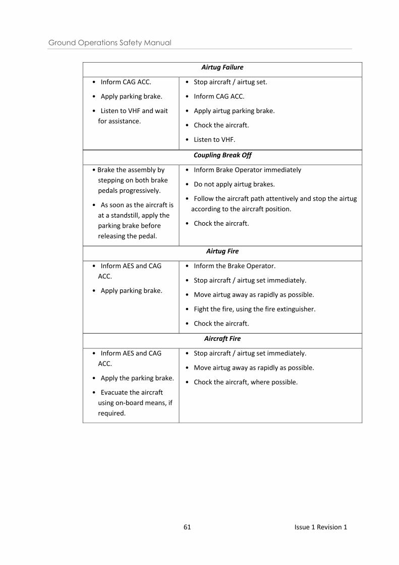
Ground Operations Safety Manual
61 Issue 1 Revision 1
Airtug Failure
• Inform CAG ACC.
• Apply parking brake.
• Listen to VHF and wait
for assistance.
• Stop aircraft / airtug set.
• Inform CAG ACC.
• Apply airtug parking brake.
• Chock the aircraft.
• Listen to VHF.
Coupling Break Off
• Brake the assembly by
stepping on both brake
pedals progressively.
• As soon as the aircraft is
at a standstill, apply the
parking brake before
releasing the pedal.
• Inform Brake Operator immediately
• Do not apply airtug brakes.
• Follow the aircraft path attentively and stop the airtug
according to the aircraft position.
• Chock the aircraft.
Airtug Fire
• Inform AES and CAG
ACC.
• Apply parking brake.
• Inform the Brake Operator.
• Stop aircraft / airtug set immediately.
• Move airtug away as rapidly as possible.
• Fight the fire, using the fire extinguisher.
• Chock the aircraft.
Aircraft Fire
• Inform AES and CAG
ACC.
• Apply the parking brake.
• Evacuate the aircraft
using on-board means, if
required.
• Stop aircraft / airtug set immediately.
• Move airtug away as rapidly as possible.
• Chock the aircraft, where possible.
Ground Operations Safety Manual
62 Issue 1 Revision 1
12 Aircraft Fuelling
12.1 General
12.1.1 The FSZ is defined as an area of at least 3 metres in any direction from any centre point of all
fuel vent exits, refuelling plugs, aircraft refuelling ports, fuel hydrants, fuel hoses and fuelling
truck (fuel dispenser).
12.1.2 The responsible ground personnel / refuelling operator shall ensure that he:
a) Is issued with a valid CAG’s ADP to drive and operate that specific equipment type;
b) Wears a high visibility safety vest at all times;
c) Does NOT smoke;
d) Observes ramp safety rules (e.g. No horseplay on the job);
e) Observes the danger areas / hazards on the ramp and take the necessary precautions for
personnel and aircraft safety.
f) Is aware of contacting AES immediately at 6541 2525 for any aircraft fuel spillage. Refer
to the CAG FSM Chapter 9, Para 9.4.1 on the reporting requirements for aircraft fuel
spillages.
g) Is aware of the location of the nearest emergency stop button;
h) Does not litter or leave any refuse or FOD within the aircraft stand;
i) Shall not consume any food or beverage and shall not feed any bird or animal;
j) Checks that there is an unobstructed vehicle escape route.
12.1.3 The fuelling operator shall ensure that the fuelling vehicle:
a) Is issued with a valid CAG’s AVP and equipped with a valid fire extinguisher and current
inspection tags;
b) Has “no smoking” signs on both sides;
c) Has externally mounted emergency engine stop controls clearly identified;
d) Is fitted with aircraft wing proximity sensors on the elevating platform;
e) Is equipped with spill containment kit;
12.2 Fuelling Vehicles Safety Driving & Parking Inside ERA
12.2.1 The following precautions shall be taken when operating fuelling vehicles within the ERA:
a) Only move fuelling vehicles towards the aircraft when all the following criteria is met:
i. Aircraft has come to a complete stop;
ii. Engines have been switched off and are spooling down;
iii. Anti-collision lights are switched off;
iv. Wheel chocks are positioned; and
v. Ground / Flight Crew communication has been established and headset man has
given the ‘thumbs up’ signal.
b) Do not approach the aircraft until all safety cones have been placed;
c) Fuelling vehicle is moved forward into fuelling position;
d) Do not drive fuelling vehicles more than 5 km per hour;
Ground Operations Safety Manual
63 Issue 1 Revision 1
e) Test the brakes as soon as possible and before leaving the depot. The approach to an
aircraft shall be such that collision will be avoided in the event of vehicle brake failure;
f) Do not use handheld PEDs when operating vehicles or equipment;
g) Do not carry extra personnel during movement of fuelling vehicles unless that person is
seated in a passenger seat provided in the vehicle or standing in a section of the vehicle
which has been constructed for standing passengers;
h) Do not drive the fuelling vehicles across the path of embarking and disembarking
passengers. Aircraft passengers always have right of way;
i) Check that there is an unobstructed vehicle escape route;
j) Do not leave any vehicle unattended with its engine running;
k) One aerobridge or mobile passenger step or integral stairs shall be positioned with the
aircraft door fully opened for evacuation of passengers when fuelling with passengers on
board;
l) Sufficient evacuation areas on ground beneath the aircraft exit doors and are clear of
obstruction.
12.3 Pre-fuelling Operations
12.3.1 The fuelling operator shall ensure:
a) Vehicle stabilizers are fully in contact with the tarmac before mounting on the elevating
platform to connect the fuelling hose to aircraft coupling;
b) Fuelling vehicle is positioned correctly to ensure that strain is not applied to fuelling
hoses when connected to the aircraft;
c) Bonding/grounding connections are established between fuelling vehicle and aircraft
before fuelling operations;
d) Lanyard connected to the hydrant pit valve is free of obstruction and readily accessible
to the fuelling operator and ground personnel;
e) Hydrant pit valve is identified by a four-winged flag, cone or equivalent;
12.4 Fuelling Operations
12.4.1 The fuelling operator shall:
a) Inform flight crew or qualified personnel onboard the aircraft when fuelling is about to
begin or has been completed;
b) Use hand held dead man device throughout the operation and remains outside the
vehicle cab at all times;
c) Ensure fuelling hoses have sufficient length to allow the fuelling platform to be fully
lowered while hoses/coupling are connected to the aircraft;
d) Ensure fuelling hoses are not entangled on equipment during movement of fuelling
platform;
e) Ensure that fuelling platform is not raised or lowered when refuelling operations are
taking place;
f) Ensure that fuelling vehicle has interlock mechanisms to prevent vehicle from moving
while hoses are connected to the aircraft;
g) Exercise extreme caution when fuelling an aircraft during lightning and thunderstorms;
Ground Operations Safety Manual
64 Issue 1 Revision 1
h) Suspend fuelling operations during severe thunderstorms;
i) Conduct post fuelling operations 360 degree walk to ensure all hoses are disconnected
and stowed correctly;
j) Clear FOD if any.
12.4.2 The refuelling operator shall shut down the refuelling operation whenever:
a) Any fuel is discovered to be leaking or spilling from fuel servicing equipment or hoses;
b) Any auxiliary or GPUs and other heating devices are not positioned at least 6 metres away
from fuelling vehicles and clear of wing tank vents. The unit shall not be disconnected or
switches-operated during fuelling;
c) Any vehicle is driven over any hose or bonding cable laid on the apron used for refuelling
aircraft;
d) Anyone is using PEDs (e.g. cell phone, camera, PDA also known as palmtop computer,
radios) within 3 metres of FSZ when refuelling is in progress, unless such device is
intrinsically-safe certified;
e) Any passengers are within 3 metres in any direction from the centre point of all fuel vent
exits, refuelling plugs, aircraft refuelling ports, fuel hydrant, fuel hoses and fuelling
vehicles.
Note: Refuelling operations to be suspended during severe thunderstorms according to
respective fuelling companies’ guidelines.
Note: Please refer to the CAG AES Fire Safety Manual for more information.
12.5 Aircraft Fuel Spillage
12.5.1 Small spills that need no emergency action shall be cleaned up with use of oil absorbent or
rags and discarded properly. Saw dusts and any other absorbent materials shall not be used.
12.5.2 In the event of an overflow of fuel from a hydrant pit, the aircraft fuelling operator shall stop
the fuel flow by releasing the Deadman switch and pulling the lanyard to shut off the
hydrant pit quick release valve. If necessary, to activate the emergency stop button.
12.5.3 For any aircraft fuel spillage, please contact AES immediately at 6541 2525. Refer to the CAG
FSM Chapter 9, Para 9.4.1 on the reporting requirements for aircraft fuel spillages.
12.5.4 Assist AES to secure the area 15 metres from the contaminated area until the affected area
has been cleaned up.
Ground Operations Safety Manual
65 Issue 1 Revision 1
13 Training & Competency of Personnel of Ground Service Providers
13.1 Introduction
13.1.1 The objective of training is to ensure that personnel are equipped with the requisite skills,
knowledge and attitude to complete their tasks in a safe and efficient manner.
13.1.2 To ensure safety, quality and proficiency on the airside, the GSP shall minimally cover all the
safety standards and procedures stated in this Ground Operations Safety Manual (GOSM)
which are relevant to the job scope of the operator.
13.1.3 Additionally, general safety guidelines as stated in Chapter 5 and human factors topics such
as communication, stress, fatigue and situational awareness should be included.
13.2 Programme Content
13.2.1 General
13.2.1.1 The following safety training programme applies to personnel performing the following
functions on the ramp:
a) Refuelling; b) Line maintenance; c) Ground handling operations; d) Operation of vehicles and GSE e.g. tractors, belt loaders; e) Supervision of ground handling operations.
13.2.2 Safety training programme
13.2.2.1 The safety training programme shall have topics covering all the following:
13.2.2.2 Safety Regulations
a) Airside regulations;
b) Safe working and operating procedures.
13.2.2.3 Hazards
a) Aircraft and vehicle movements;
b) Jet blast;
c) Aircraft fuelling and fuel spills;
d) Adverse weather conditions.
13.2.2.4 Human factors
a) Communications;
b) Stress;
c) Fatigue;
d) Situational awareness.
13.2.2.5 Airside Markings and Signage
a) Roadways;
Ground Operations Safety Manual
66 Issue 1 Revision 1
b) Aircraft parking stands.
13.2.2.6 Foreign Object Debris
a) FOD detection;
b) FOD prevention;
c) FOD removal.
13.2.2.7 Personal Protection Equipment (PPE)
a) Hi-visibility safety vest;
b) Protective gears.
13.2.2.8 Emergency Situations and Reporting Procedures
a) Fuel/hydraulic spillage;
b) Vehicular incident;
c) Aircraft incident.
13.2.3 Functional safety training programme
13.2.3.1 Personnel shall, as appropriate to their job function, receive training on the following
applicable subjects:
13.2.3.2 Aircraft Handling and Loading
a) Operating procedures;
b) Aircraft movement operations;
c) Securing of load, ULD, pallet/container dollies and baggage trolleys;
d) Docking and operation of equipment.
13.2.3.3 Aircraft Ground Movement
a) Operating procedures;
b) Aircraft movement operations;
c) Operation of equipment including (dis)connection procedures;
d) Airfield layout;
e) Standard phraseology.
13.2.3.4 Passenger Loading Bridge
a) Operating procedures;
b) Emergency switches and cut-offs.
13.2.3.5 Aircraft Docking Guidance System/Marshalling
a) Operating procedures;
b) Use of Aircraft Docking Guidance System
c) Hand signals
13.2.3.6 Refuelling
a) Operating procedures;
b) Safety during aircraft refuelling.
Ground Operations Safety Manual
67 Issue 1 Revision 1
13.2.4 Structure
13.2.4.1 Training should be a combination of theoretical and practical skills training to verify the
learners understanding of, and ability to complete, the task being trained.
13.2.4.2 There shall be an evaluation at the end of the training for the following ground handling
activities:
a) Aircraft docking guidance system/ manual marshalling;
b) Operation of passenger loading bridge;
c) Operation of motorised ground support equipment used for aircraft handling and
loading;
d) Aircraft pushback;
e) Aircraft towing;
f) Aircraft fuelling.
13.3 Refresher Training Requirements
13.3.1 The GSP shall clearly state down the competency which requires refresher training. There
shall be a system and process to track and make sure that all staff attend the required
refresher training on time.
13.3.2 The GSP shall have a system and process to track all the staff training record and make sure
that only trained staff are deployed for operations. This requirement also applies for the
contractors engaged by the GSP. The GSP shall be able to demonstrate that they have
oversight on the contractors training and also make sure that only trained contractors are
being deployed for operations.
13.4 Documentation
13.4.1 Training materials
13.4.1.1 The GSP must be able to demonstrate that the relevant standard operating procedures
have been suitably translated into training materials for effective delivery to the staff. The
training materials should also include risk communication components whenever
applicable, that is to say, explain to staff the risk and hazards involved when certain
procedures or steps are not being followed.
13.4.1.2 There shall also be a system for updating and documentation control of training material.
Changes to processes or equipment shall be communicated to relevant personnel and
appropriate additional information and training shall be delivered.
13.4.2 Training records
13.4.2.1 All training programmes must be documented including:
a) Description of the content of the training programmes; b) Induction, “on the job” and refresher/recurrent courses;
Ground Operations Safety Manual
68 Issue 1 Revision 1
c) Records of completed training; d) Schedule of planned training courses.
13.4.2.2 The GSP shall have a system in place for the retention of training records for a period
stipulated by the GSP.
13.4.2.3 All training, assessments and competencies shall be documented in a timely and consistent
manner.
13.4.2.4 The record shall identify the date when the particular subject matter has been delivered to
the learner.
13.4.2.5 Training content and records shall be made available for review by Chang Airport Group
when required.
13.5 Competency of Trainer, Assessor, Buddy for the On-Job Training
13.5.1 Theoretical and practical skills training shall be conducted by personnel who have
demonstrated the skills to deliver the training effectively, and who have competence
(knowledge, skill and experience) in the subjects to be instructed.
13.5.2 Assessments shall be conducted by persons who have appropriate knowledge, skills and
experience in the functions being assessed.
13.5.3 For training which has an on-the-job training (OJT) component, the ground service providers
(GSPs) should also establish clear criteria in the selection of the OJT mentor, trainer and
assessor.
13.5.4 Trainers shall keep themselves current in the subjects that they are required to conduct
training on
13.6 Training for Aircraft Docking Guidance Systems/Manual Marshalling
13.6.1 Initial training of ADGS and manual marshalling shall comprise of both theory and practical
components.
13.6.2 Operators shall have experience operating the ADGS and conducting manual marshalling on
live flights under trainer or mentor supervision before operating independently.
13.6.3 Operators who are qualified to operate the ADGS and conduct manual marshalling shall
undergo refresher training every two (2) years. All training records shall be retained by the
GSP and provided to CAG upon request.
Ground Operations Safety Manual
69 Issue 1 Revision 1
13.7 Training for Aircraft Docking Guidance Systems/Manual Marshalling
13.7.1 Initial training of ADGS and manual marshalling shall comprise of both theory and practical
components.
13.7.2 Operators shall have experience operating the ADGS and conducting manual marshalling on
live flights under trainer or mentor supervision before operating independently.
13.7.3 Operators who are qualified to operate the ADGS and conduct manual marshalling shall
undergo refresher training every two (2) years. All training records shall be retained by the
GSP and provided to CAG upon request.
13.7.4 The GSP should establish measures to ascertain the competency of new operators and
document the measures.
13.8 Training for Passenger Loading Bridge Operations
13.8.1 All PLB operators must be licensed by CAG to operate the PLB and hold a valid Class ‘A’ ADP.
Operators shall be conversant with emergency procedures and comply with SOPs located
next to all PLB consoles and other instructions which may be issued by CAG. Operators are
to use the “Auto-Dock” function of the PLB console, if the PLB console is equipped with this
function.
13.8.2 Operators who are qualified to operate the PLB shall undergo refresher courses every two
(2) years. All training records shall be retained by the GSP and provided to CAG upon
request.
Ground Operations Safety Manual
70 Issue 1 Revision 1
14 Ground Support Equipment Maintenance Programme
14.1 General
14.1.1 A GSE is any piece of mobile equipment, whether or not powered or self-propelled, purpose
designed, built and used for ground handling, servicing or field maintenance of aircraft on
the ramp.
14.1.2 The GSP shall have a maintenance programme that ensures that GSE remains safe to
operate and in good condition. The GSP shall have a system in place that prevents operation
of any equipment that is not deemed to be in a safe and serviceable condition.
14.1.3 If the GSP outsources the maintenance functions to external organizations, the GSP retains
overall responsibility of such functions, and must demonstrate processes for monitoring the
applicable external organizations.
14.2 Maintenance Programme
14.2.1 The GSP shall ensure that the maintenance programme includes the following:
a) Preventive maintenance that is conducted minimally in accordance with OEM
requirements;
b) Corrective maintenance
14.2.2 Periodic checks/servicing
14.2.2.1 This inspection shall be performed minimally in accordance to the schedule recommended
by OEM, including necessary servicing and/or replacement of components.
14.2.2.2 The GSP shall have in place a defect reporting process, including corrective action plans to
address GSE faults.
14.2.3 Documentation
14.2.3.1 The GSP shall ensure that maintenance records are retained according to the stipulated
period by the GSP.
14.3 Treatment of Unserviceable GSE
14.3.1 The GSP shall ensure that unserviceable GSE is removed from operations for repair and/or
maintenance. The unserviceable GSE shall be indicated with out of service markers to ensure
it is not being used for operations.
Ground Operations Safety Manual
71 Issue 1 Revision 1
14.4 Fire Protection
14.4.1 Fire is one of the most dangerous threats to an aircraft. GSPs shall ensure that GSEs are
equipped with fire protection systems.
Note: Operators shall not leave equipment unattended with engine running (with the
exception of GPU).
Ground Operations Safety Manual
72 Issue 1 Revision 1
15 Contractor Management
15.1 General
15.1.1 Contractor management is the managing of outsourced work performed for an individual
company.
15.1.2 If any part of the ground handling functions is outsourced to an external third-party, i.e.
contractors, the GSP shall establish direct oversight to ensure that the function is conducted
safely.
15.1.3 All safety information promulgated by CAG must also be disseminated to their contractors.
15.1.4 The GSP shall ensure that all contractors are trained before deployment. There shall be a
process to monitor their training records to make sure that they also attend the necessary
refresher training.
15.1.5 The GSP shall always maintain an updated list of contractors and to provide to CAG upon
request.
15.1.6 The GSP shall inform CAG at least two weeks in advance of any planned changes in
contractor or deployment of existing contractors. For example, changes in provision of
handling services to airlines.
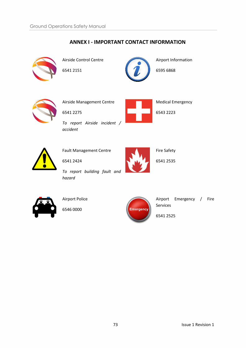
Ground Operations Safety Manual
73 Issue 1 Revision 1
ANNEX I - IMPORTANT CONTACT INFORMATION
Airside Control Centre
6541 2151
Airport Information
6595 6868
Airside Management Centre
6541 2275
To report Airside incident /
accident
Medical Emergency
6543 2223
Fault Management Centre
6541 2424
To report building fault and
hazard
Fire Safety
6541 2535
Airport Police
6546 0000
Airport Emergency / Fire
Services
6541 2525
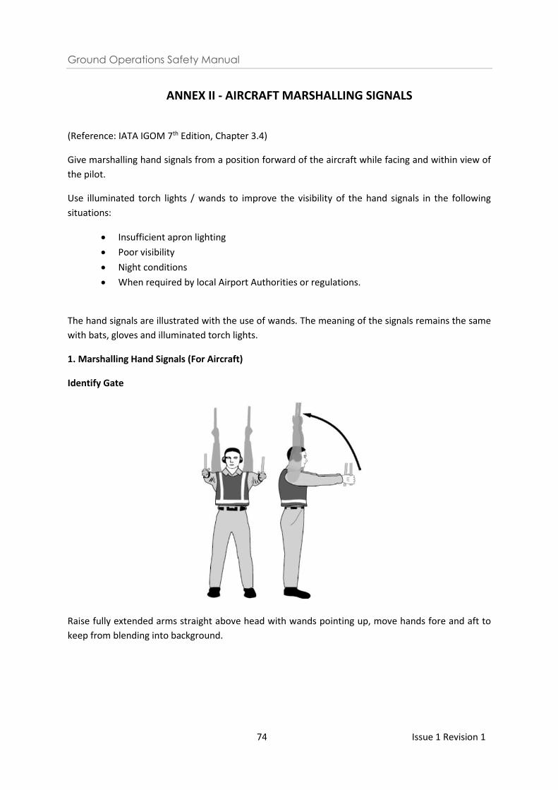
Ground Operations Safety Manual
74 Issue 1 Revision 1
ANNEX II - AIRCRAFT MARSHALLING SIGNALS
(Reference: IATA IGOM 7th Edition, Chapter 3.4)
Give marshalling hand signals from a position forward of the aircraft while facing and within view of
the pilot.
Use illuminated torch lights / wands to improve the visibility of the hand signals in the following
situations:
• Insufficient apron lighting
• Poor visibility
• Night conditions
• When required by local Airport Authorities or regulations.
The hand signals are illustrated with the use of wands. The meaning of the signals remains the same
with bats, gloves and illuminated torch lights.
1. Marshalling Hand Signals (For Aircraft)
Identify Gate
Raise fully extended arms straight above head with wands pointing up, move hands fore and aft to
keep from blending into background.
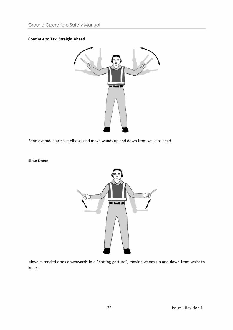
Ground Operations Safety Manual
75 Issue 1 Revision 1
Continue to Taxi Straight Ahead
Bend extended arms at elbows and move wands up and down from waist to head.
Slow Down
Move extended arms downwards in a “patting gesture”, moving wands up and down from waist to
knees.
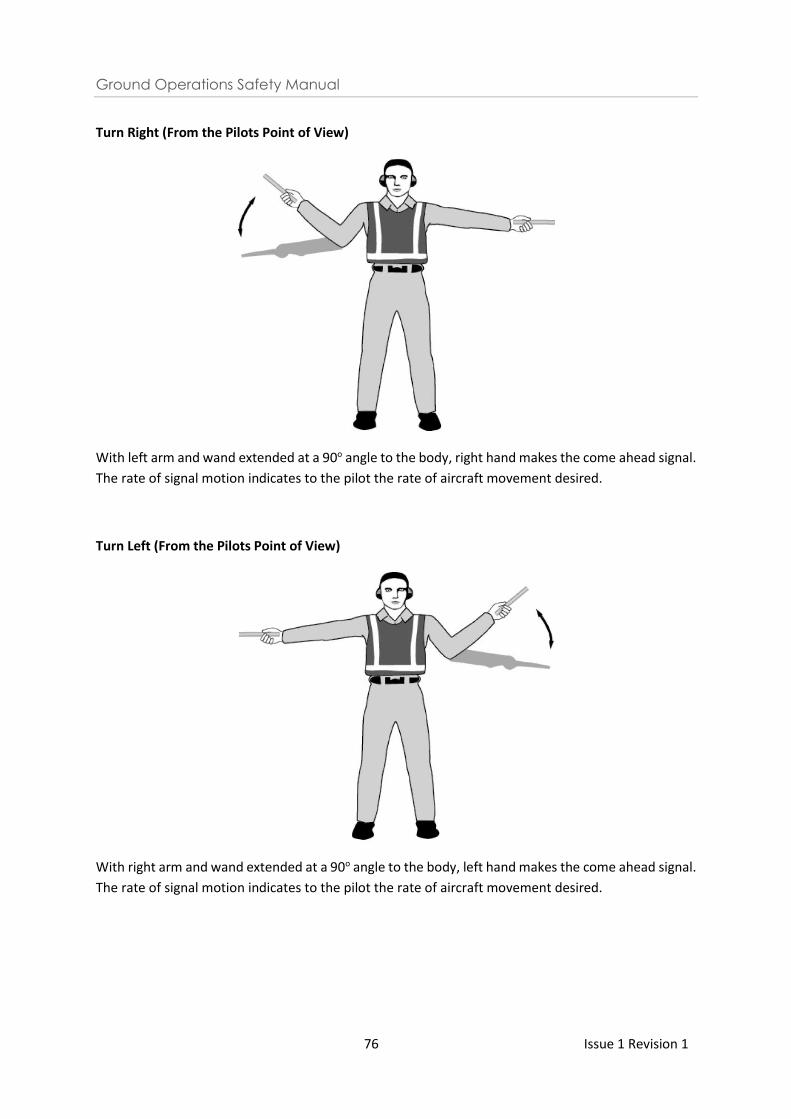
Ground Operations Safety Manual
76 Issue 1 Revision 1
Turn Right (From the Pilots Point of View)
With left arm and wand extended at a 90o angle to the body, right hand makes the come ahead signal.
The rate of signal motion indicates to the pilot the rate of aircraft movement desired.
Turn Left (From the Pilots Point of View)
With right arm and wand extended at a 90o angle to the body, left hand makes the come ahead signal.
The rate of signal motion indicates to the pilot the rate of aircraft movement desired.
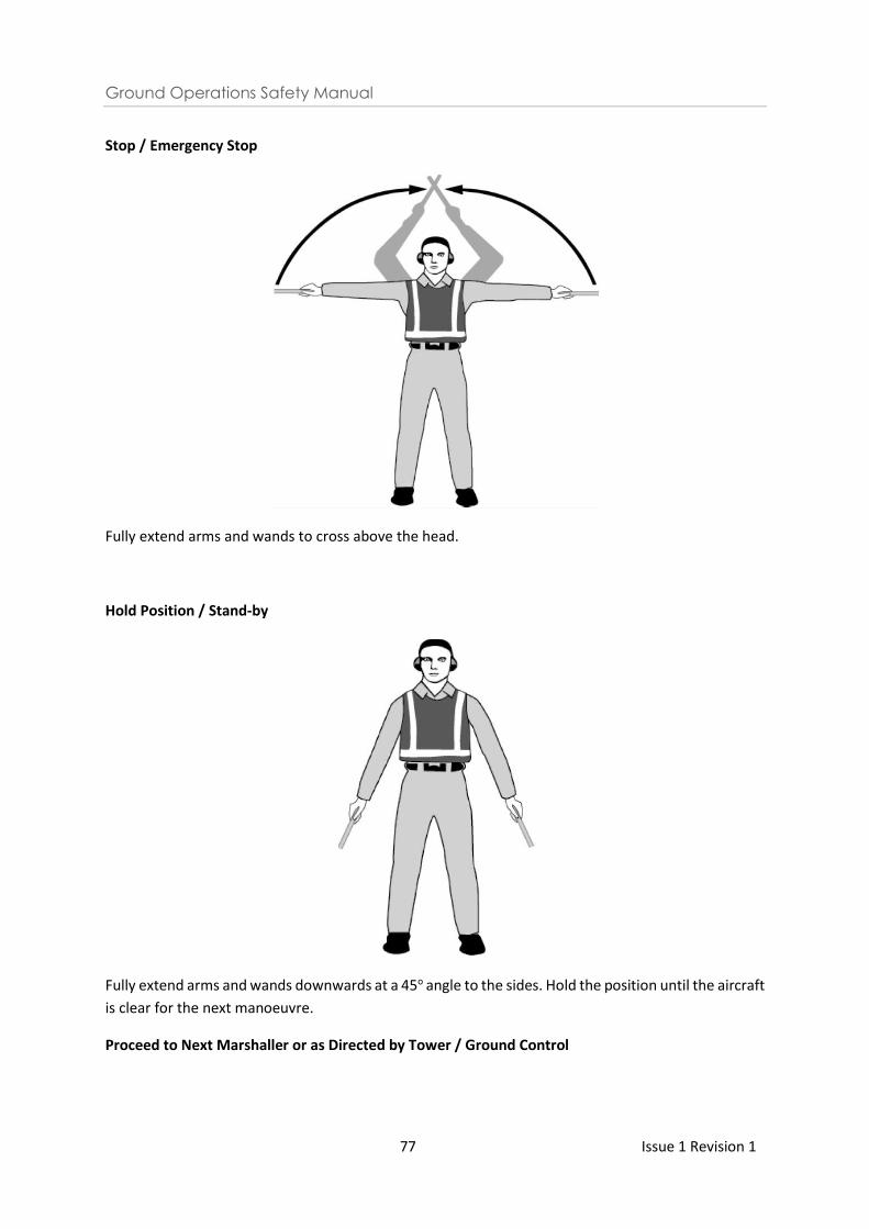
Ground Operations Safety Manual
77 Issue 1 Revision 1
Stop / Emergency Stop
Fully extend arms and wands to cross above the head.
Hold Position / Stand-by
Fully extend arms and wands downwards at a 45o angle to the sides. Hold the position until the aircraft
is clear for the next manoeuvre.
Proceed to Next Marshaller or as Directed by Tower / Ground Control
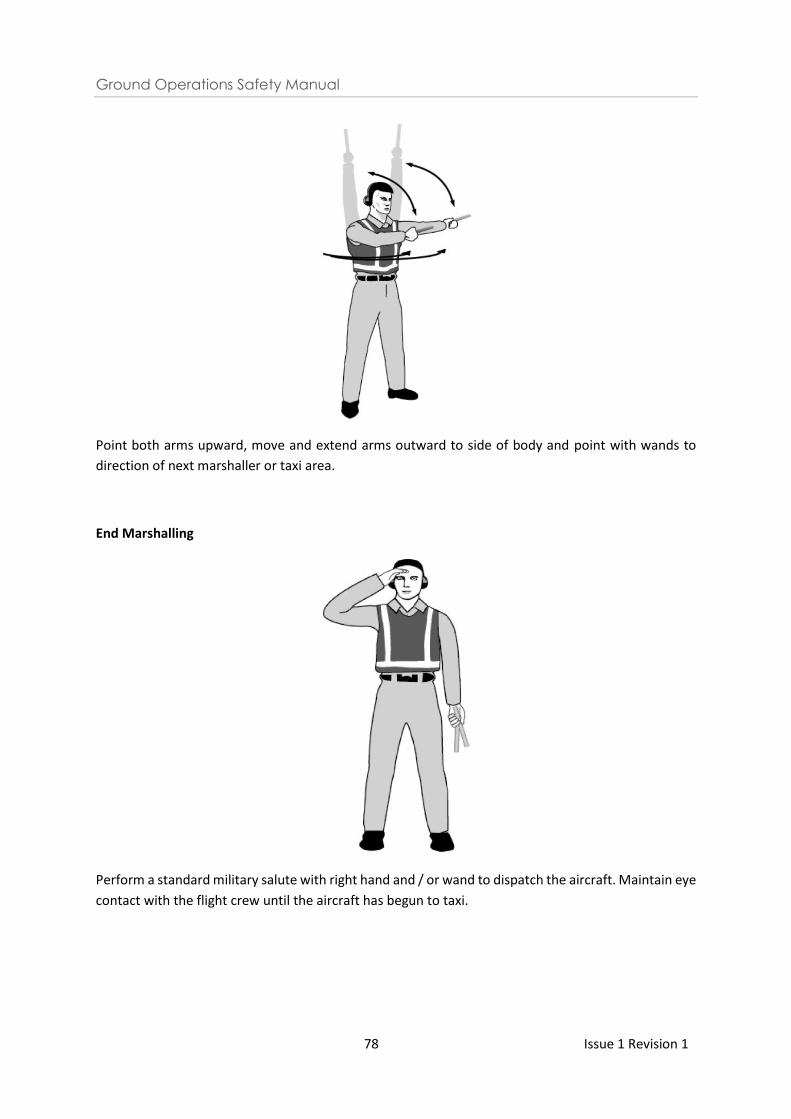
Ground Operations Safety Manual
78 Issue 1 Revision 1
Point both arms upward, move and extend arms outward to side of body and point with wands to
direction of next marshaller or taxi area.
End Marshalling
Perform a standard military salute with right hand and / or wand to dispatch the aircraft. Maintain eye
contact with the flight crew until the aircraft has begun to taxi.
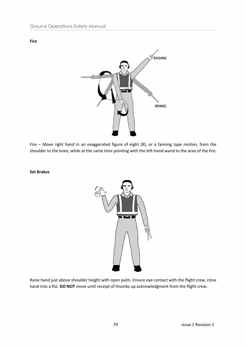
Ground Operations Safety Manual
79 Issue 1 Revision 1
Fire
Fire – Move right hand in an exaggerated figure of eight (8), or a fanning type motion, from the
shoulder to the knee, while at the same time pointing with the left-hand wand to the area of the fire.
Set Brakes
Raise hand just above shoulder height with open palm. Ensure eye contact with the flight crew, close
hand into a fist. DO NOT move until receipt of thumbs up acknowledgment from the flight crew.
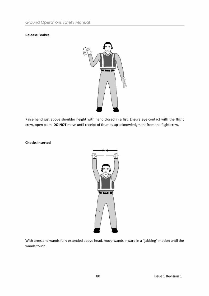
Ground Operations Safety Manual
80 Issue 1 Revision 1
Release Brakes
Raise hand just above shoulder height with hand closed in a fist. Ensure eye contact with the flight
crew, open palm. DO NOT move until receipt of thumbs up acknowledgment from the flight crew.
Chocks Inserted
With arms and wands fully extended above head, move wands inward in a “jabbing” motion until the
wands touch.
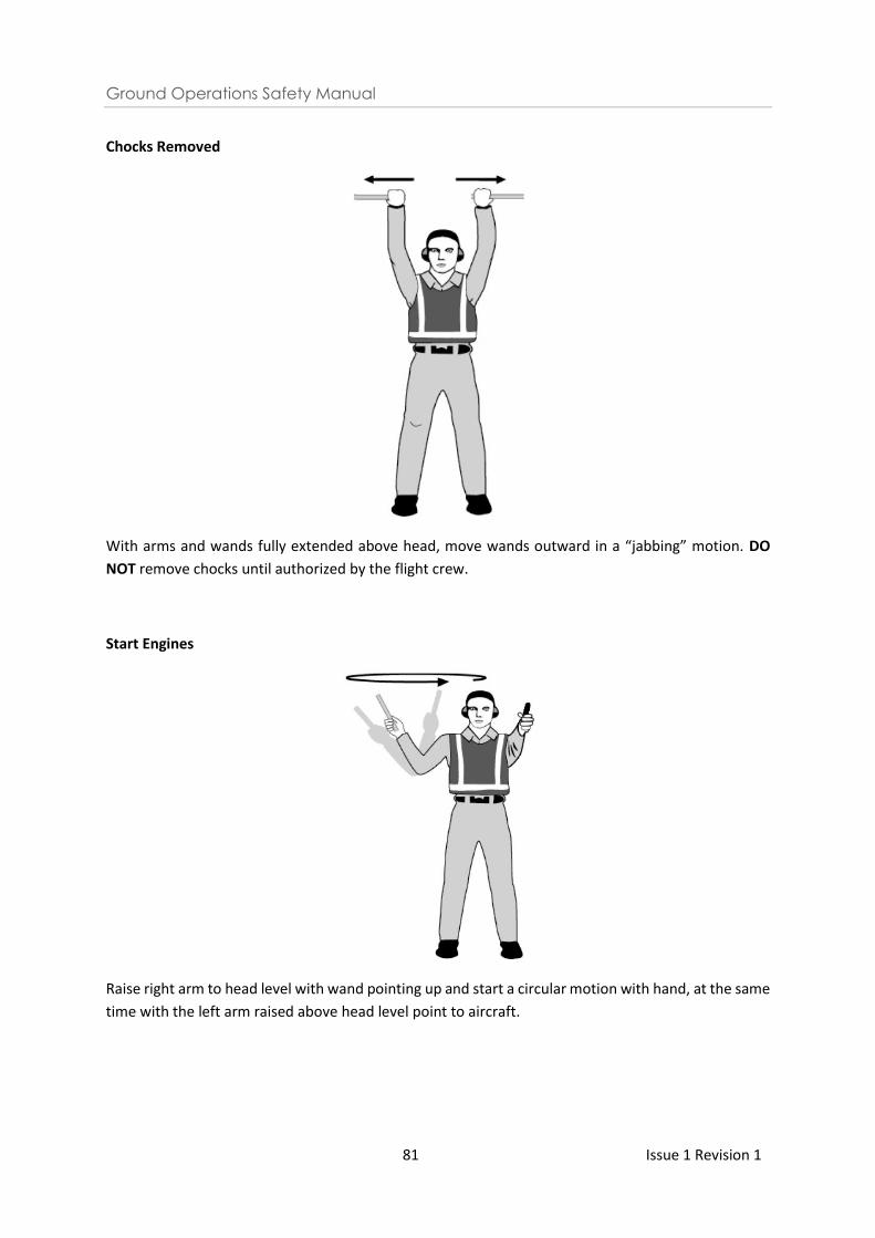
Ground Operations Safety Manual
81 Issue 1 Revision 1
Chocks Removed
With arms and wands fully extended above head, move wands outward in a “jabbing” motion. DO
NOT remove chocks until authorized by the flight crew.
Start Engines
Raise right arm to head level with wand pointing up and start a circular motion with hand, at the same
time with the left arm raised above head level point to aircraft.
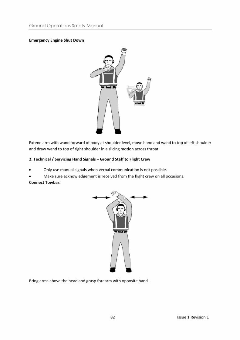
Ground Operations Safety Manual
82 Issue 1 Revision 1
Emergency Engine Shut Down
Extend arm with wand forward of body at shoulder level, move hand and wand to top of left shoulder
and draw wand to top of right shoulder in a slicing motion across throat.
2. Technical / Servicing Hand Signals – Ground Staff to Flight Crew
• Only use manual signals when verbal communication is not possible.
• Make sure acknowledgement is received from the flight crew on all occasions.
Connect Towbar:
Bring arms above the head and grasp forearm with opposite hand.
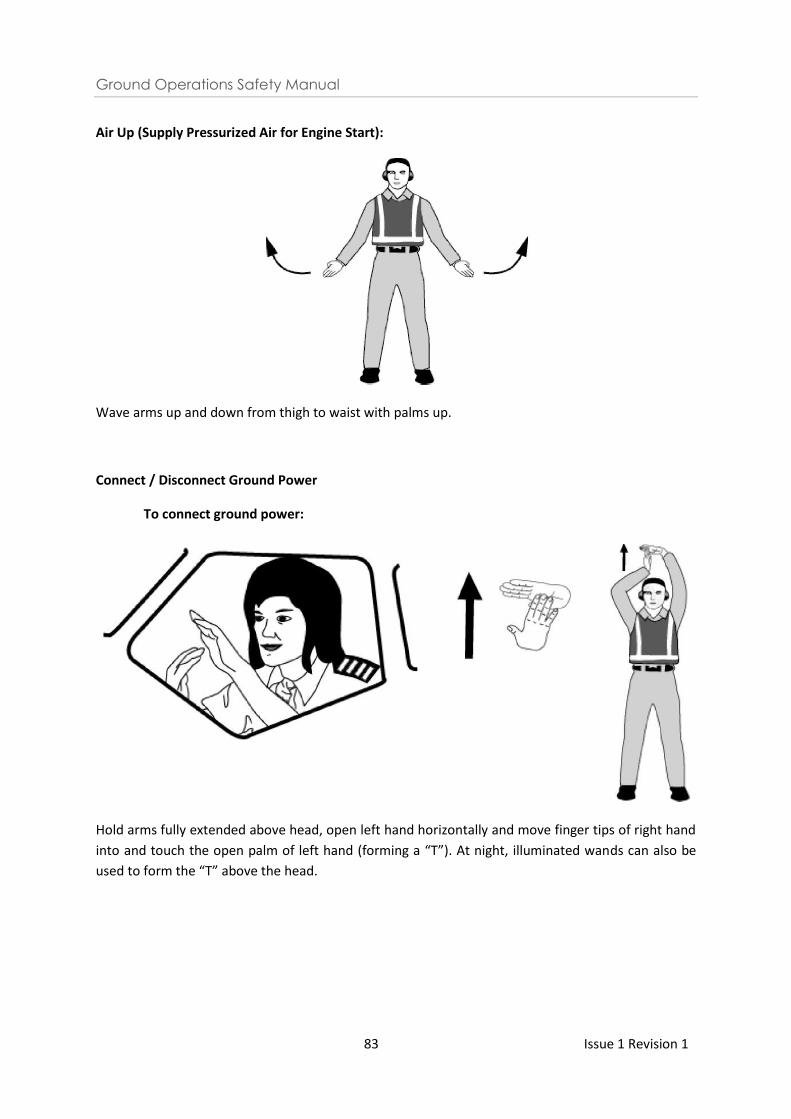
Ground Operations Safety Manual
83 Issue 1 Revision 1
Air Up (Supply Pressurized Air for Engine Start):
Wave arms up and down from thigh to waist with palms up.
Connect / Disconnect Ground Power
To connect ground power:
Hold arms fully extended above head, open left hand horizontally and move finger tips of right hand
into and touch the open palm of left hand (forming a “T”). At night, illuminated wands can also be
used to form the “T” above the head.
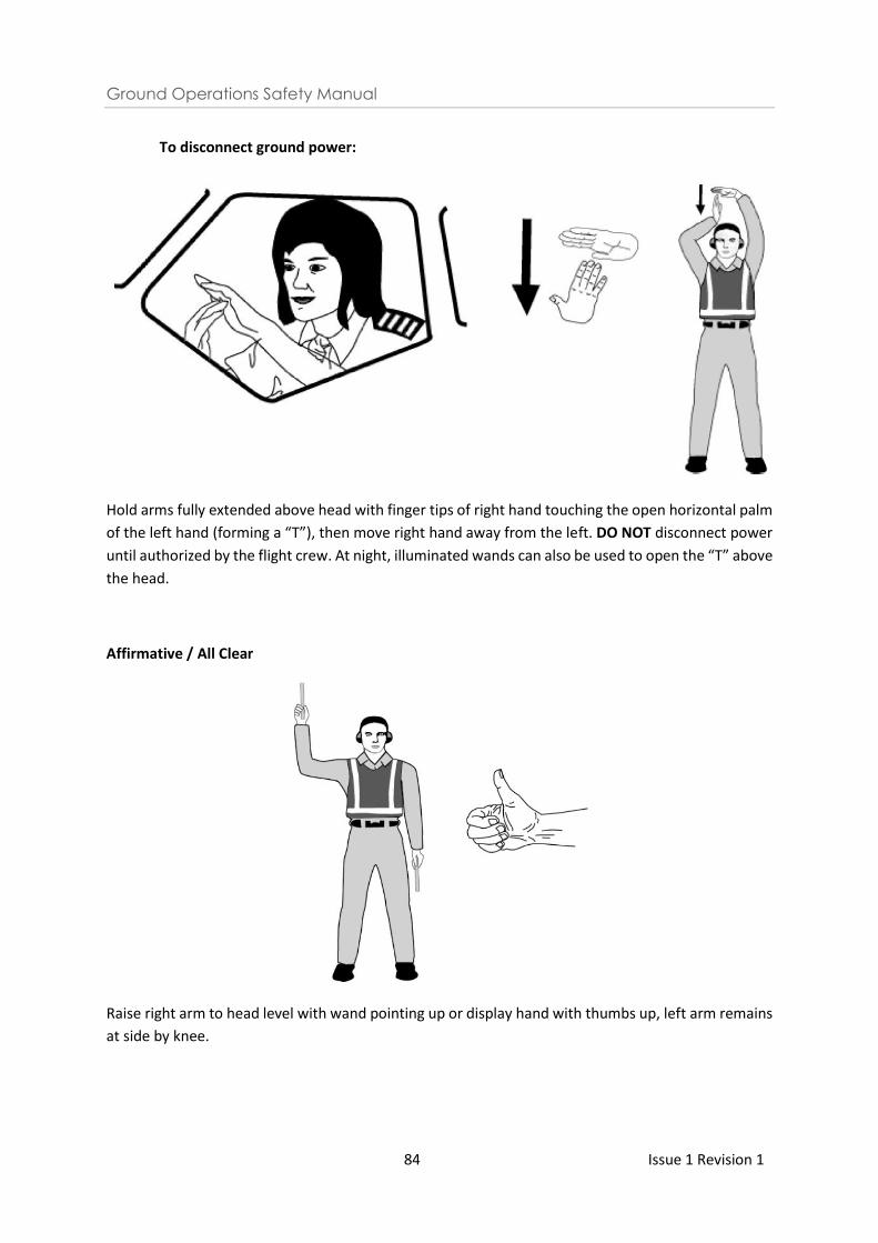
Ground Operations Safety Manual
84 Issue 1 Revision 1
To disconnect ground power:
Hold arms fully extended above head with finger tips of right hand touching the open horizontal palm
of the left hand (forming a “T”), then move right hand away from the left. DO NOT disconnect power
until authorized by the flight crew. At night, illuminated wands can also be used to open the “T” above
the head.
Affirmative / All Clear
Raise right arm to head level with wand pointing up or display hand with thumbs up, left arm remains
at side by knee.
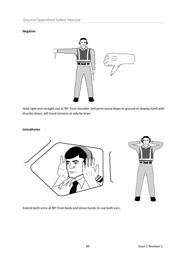
Ground Operations Safety Manual
85 Issue 1 Revision 1
Negative
Hold right arm straight out at 90o from shoulder and point wand down to ground or display hand with
thumbs down, left hand remains at side by knee.
Interphones
Extend both arms at 90o from body and move hands to cup both ears.
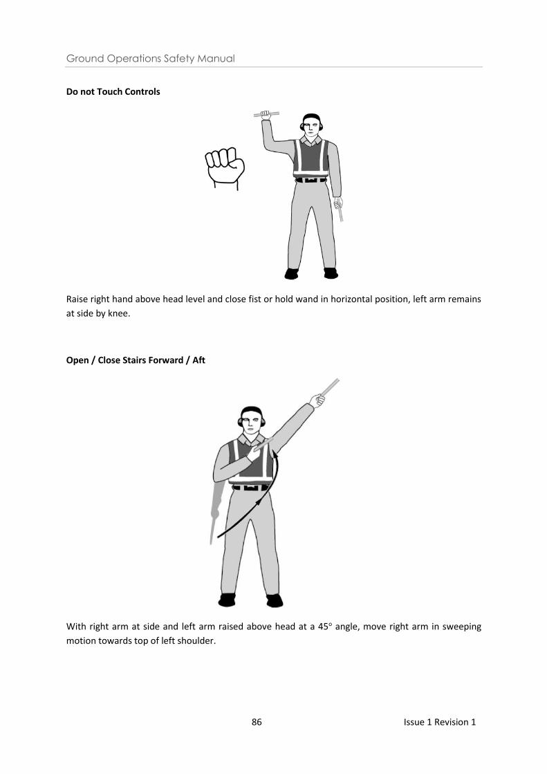
Ground Operations Safety Manual
86 Issue 1 Revision 1
Do not Touch Controls
Raise right hand above head level and close fist or hold wand in horizontal position, left arm remains
at side by knee.
Open / Close Stairs Forward / Aft
With right arm at side and left arm raised above head at a 45o angle, move right arm in sweeping
motion towards top of left shoulder.
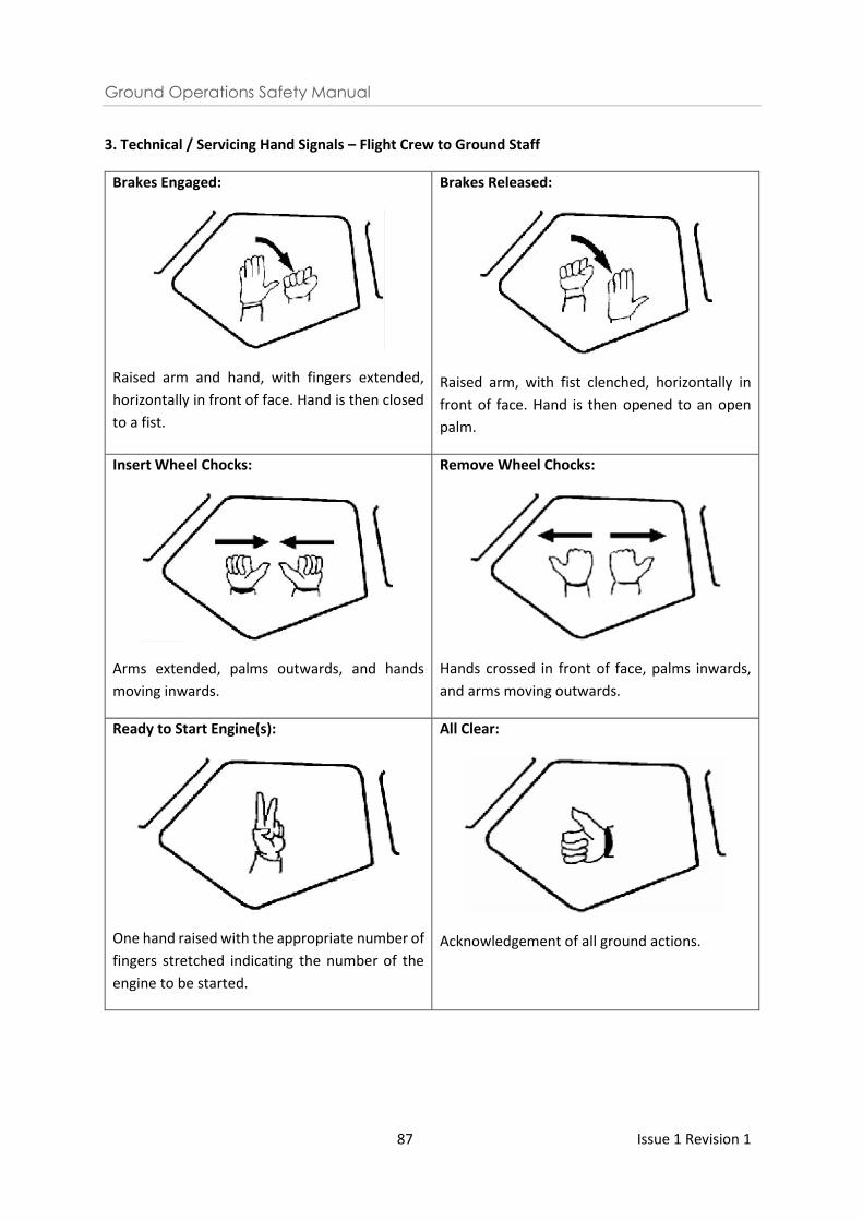
Ground Operations Safety Manual
87 Issue 1 Revision 1
3. Technical / Servicing Hand Signals – Flight Crew to Ground Staff
Brakes Engaged:
Raised arm and hand, with fingers extended,
horizontally in front of face. Hand is then closed
to a fist.
Brakes Released:
Raised arm, with fist clenched, horizontally in
front of face. Hand is then opened to an open
palm.
Insert Wheel Chocks:
Arms extended, palms outwards, and hands
moving inwards.
Remove Wheel Chocks:
Hands crossed in front of face, palms inwards,
and arms moving outwards.
Ready to Start Engine(s):
One hand raised with the appropriate number of
fingers stretched indicating the number of the
engine to be started.
All Clear:
Acknowledgement of all ground actions.
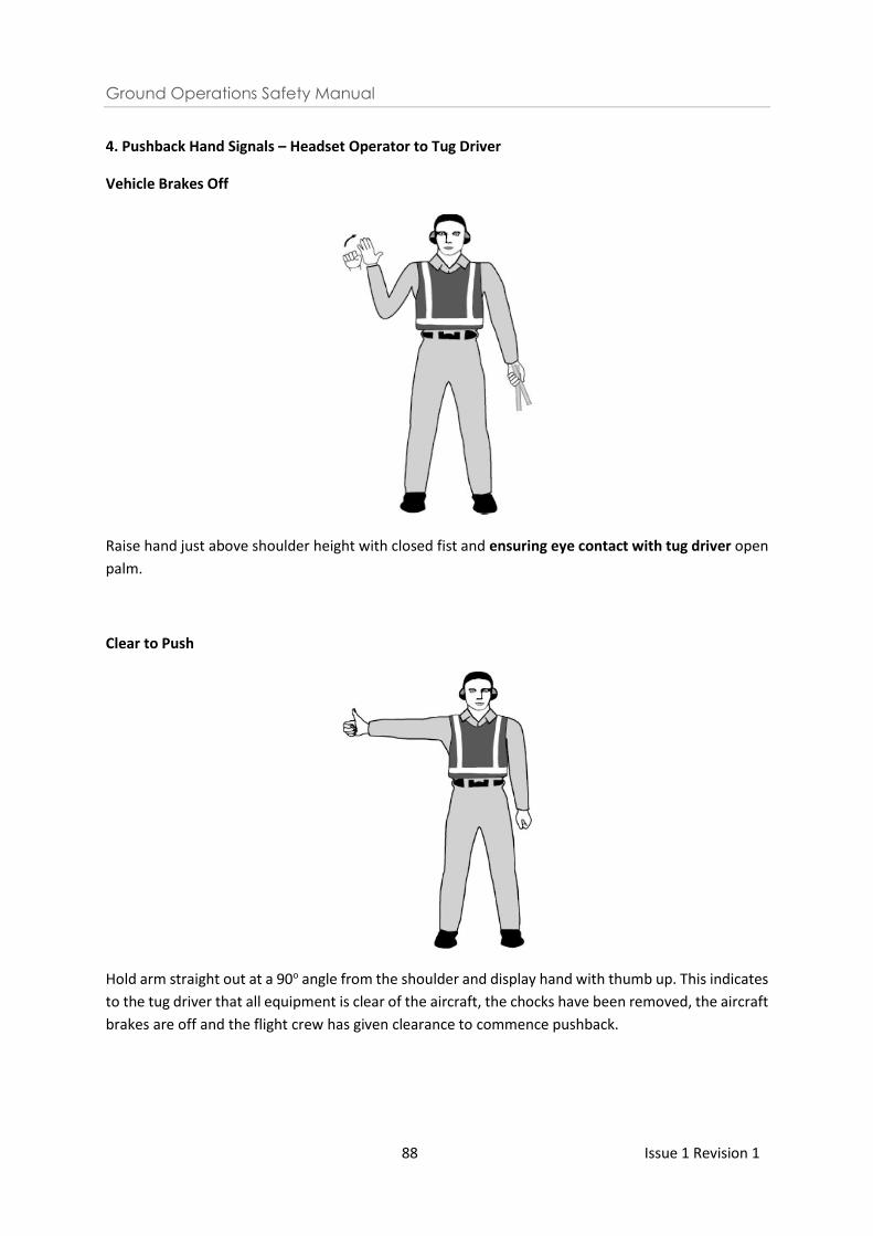
Ground Operations Safety Manual
88 Issue 1 Revision 1
4. Pushback Hand Signals – Headset Operator to Tug Driver
Vehicle Brakes Off
Raise hand just above shoulder height with closed fist and ensuring eye contact with tug driver open
palm.
Clear to Push
Hold arm straight out at a 90o angle from the shoulder and display hand with thumb up. This indicates
to the tug driver that all equipment is clear of the aircraft, the chocks have been removed, the aircraft
brakes are off and the flight crew has given clearance to commence pushback.
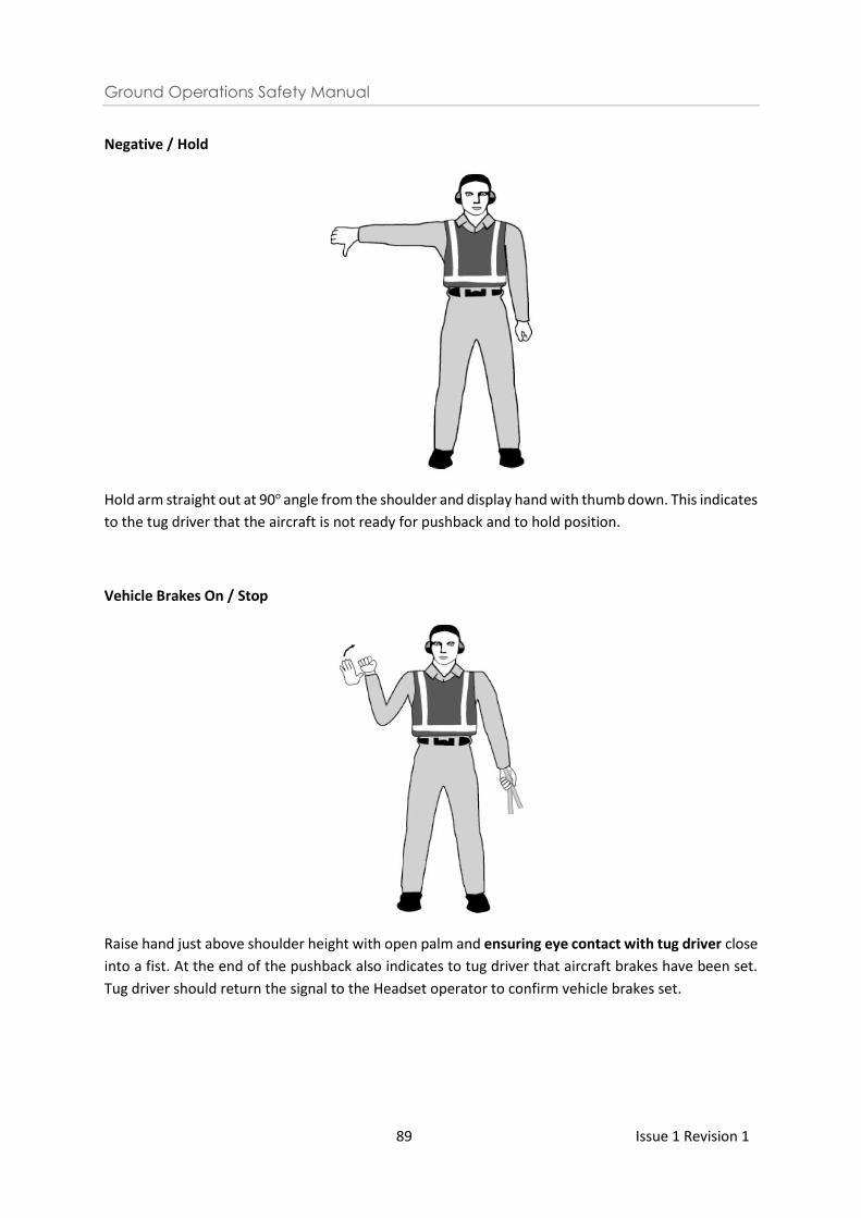
Ground Operations Safety Manual
89 Issue 1 Revision 1
Negative / Hold
Hold arm straight out at 90o angle from the shoulder and display hand with thumb down. This indicates
to the tug driver that the aircraft is not ready for pushback and to hold position.
Vehicle Brakes On / Stop
Raise hand just above shoulder height with open palm and ensuring eye contact with tug driver close
into a fist. At the end of the pushback also indicates to tug driver that aircraft brakes have been set.
Tug driver should return the signal to the Headset operator to confirm vehicle brakes set.
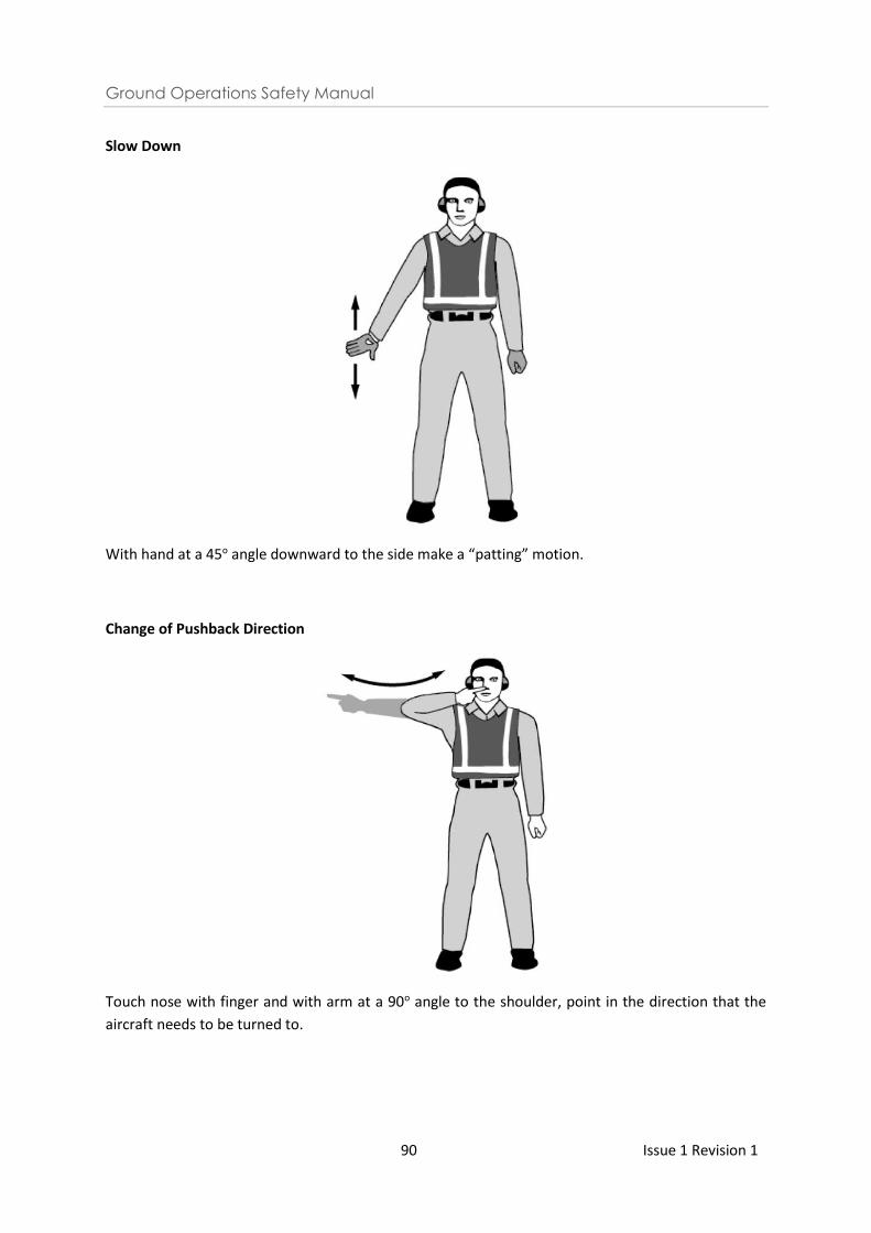
Ground Operations Safety Manual
90 Issue 1 Revision 1
Slow Down
With hand at a 45o angle downward to the side make a “patting” motion.
Change of Pushback Direction
Touch nose with finger and with arm at a 90o angle to the shoulder, point in the direction that the
aircraft needs to be turned to.
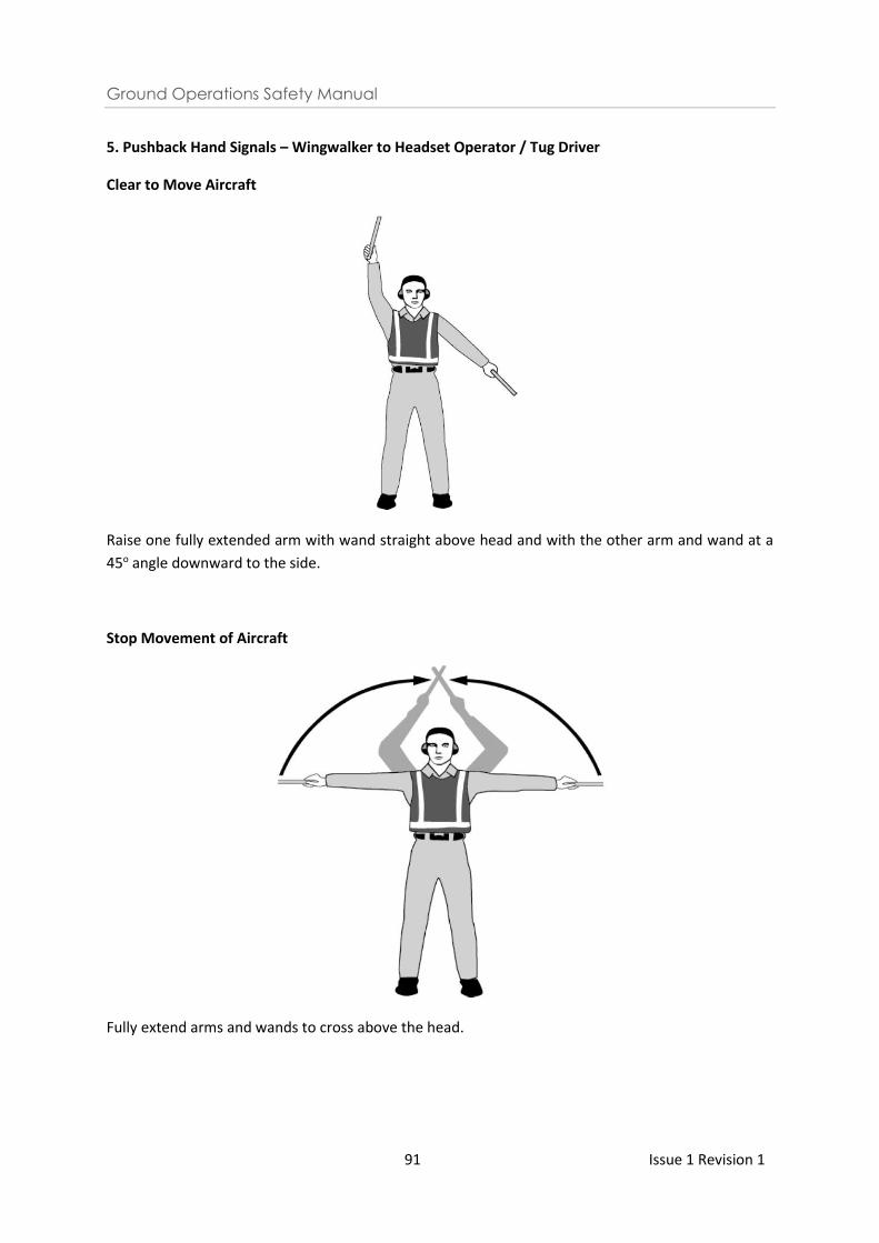
Ground Operations Safety Manual
91 Issue 1 Revision 1
5. Pushback Hand Signals – Wingwalker to Headset Operator / Tug Driver
Clear to Move Aircraft
Raise one fully extended arm with wand straight above head and with the other arm and wand at a
45o angle downward to the side.
Stop Movement of Aircraft
Fully extend arms and wands to cross above the head.
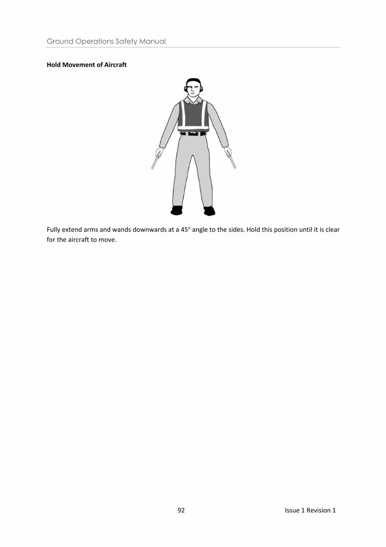
Ground Operations Safety Manual
92 Issue 1 Revision 1
Hold Movement of Aircraft
Fully extend arms and wands downwards at a 45o angle to the sides. Hold this position until it is clear
for the aircraft to move.

Ground Operations Safety Manual
93 Issue 1 Revision 1
ANNEX III - AIRCRAFT ENGINE RUN-UP
1 Conditions and Responsibilities for Engine Run at Aircraft Stands
1.1 Aircraft engine run-up on the aircraft stands including the engine run-up stands is subject to
the approval from CAG Airside Control Centre.
1.2 It is the responsibility of the person conducting the engine run-up to ensure all equipment,
vehicles and personnel are well clear of the slipstream and blast areas prior to
commencement of and during the run-up. The personnel is to discontinue the run when any
movement, including aircraft, behind the aircraft conducting the run is detected. In addition,
the personnel is also to ensure the following during the engine run-up:
a) The aircraft wheels are adequately chocked and the aircraft cannot move forward
under any circumstances;
b) Where the engine run is carried out at the contact gates, the passenger loading
bridge shall be retracted from the aircraft;
c) The aircraft anti-collision lights are activated and remain on during the entire ground
run period; and
d) The engine run is carried out in accordance to the permitted duration and power (e.g.
idle power).
1.3 When ready to start, the person intending to conduct the engine run-up shall call the CAG
Airside Control Centre for approval on radio frequency VHF 121.9 MHz and thereafter,
maintain a continuous listening watch until the engine run-up operation is completed.
1.4 The Duty Airside Controller may, even after approval has been granted, request the engine
run-up to be discontinued if other operations of the airport are affected.
2 Location of Engine Run-up
2.1 Subject to the approval from CAG Airside Control Centre, engine run may be carried out at
the following aircraft stands at Changi Airport:
(a) Contact gates – idle power engine run on one engine for up to 5 minutes only;
(b) Remote stands except stands 400 to 404 – idle power engine run up to 5 minutes
only;
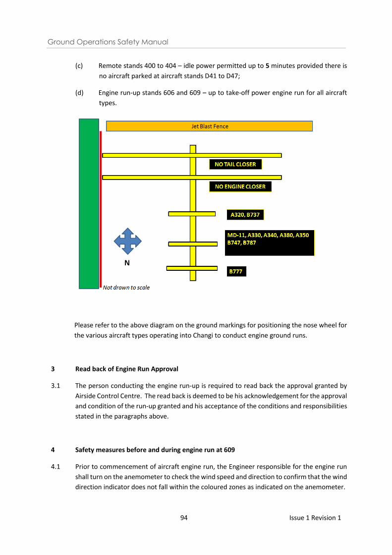
Ground Operations Safety Manual
94 Issue 1 Revision 1
(c) Remote stands 400 to 404 – idle power permitted up to 5 minutes provided there is
no aircraft parked at aircraft stands D41 to D47;
(d) Engine run-up stands 606 and 609 – up to take-off power engine run for all aircraft
types.
Please refer to the above diagram on the ground markings for positioning the nose wheel for
the various aircraft types operating into Changi to conduct engine ground runs.
3
3.1
Read back of Engine Run Approval
The person conducting the engine run-up is required to read back the approval granted by
Airside Control Centre. The read back is deemed to be his acknowledgement for the approval
and condition of the run-up granted and his acceptance of the conditions and responsibilities
stated in the paragraphs above.
4
4.1
Safety measures before and during engine run at 609
Prior to commencement of aircraft engine run, the Engineer responsible for the engine run
shall turn on the anemometer to check the wind speed and direction to confirm that the wind
direction indicator does not fall within the coloured zones as indicated on the anemometer.
Ground Operations Safety Manual
95 Issue 1 Revision 1
4.2
In the event that the wind direction falls within the coloured zones and the wind speed
exceeds the limit indicated, the red warning light will be activated. The engineer shall than
reduce engine power to idle or lower and inform Airside Control Centre on the change in
engine power.
Ground Operations Safety Manual
96 Issue 1 Revision 1
ANNEX IV - COMPASS SWING CALIBRATION (CSC) CHECK
1 The compass swing calibration (CSC) site located on taxiway NC2 behind stands 304 and 305
has been in operation since 10 April 2004.
2 Operating Hours of the CSC
2.1 The use of the CSC is allowed only between 0200LT and 0600LT.
3 Advance Booking
3.1 Airlines, aircraft operators or its handling agents are to provide at least 3 working days’ notice
in writing to CAAS Changi Tower and CAG Airside Control Centre for booking of the CSC site.
Urgent requests with at least 1 working days’ notice in writing would be facilitated on a case-
by-case basis.
3.2 Booking for the CSC site is subjected to acceptance by CAAS Changi Tower and CAG Airside
Control Centre. Airlines, aircraft operators or its handling agents should not assume that their
booking in writing is accepted and they are to call the CAG Airside Control Centre at least 24
hrs before the planned compass swing check to confirm acceptance of the booking.
4 Towing of Aircraft to CSC Site
4.1 Prior to the approved time for compass swing calibration checks, the towing crew shall
contact CAG Airside Control Centre on VHF 121.9 MHz for approval to tow the aircraft to the
CSC site. CAG Airside Control Centre shall coordinate the towing request with Changi Tower.
4.2 Upon reaching the CSC site on taxiway NC2, the towing crew shall hold the aircraft with its
nose wheel at the stop line position on the centreline of taxiway NC2 between N1 and N3,
depending on its direction of tow.
4.3 The towing crew shall inform CAG Airside Control Centre that the aircraft has stopped at the
designated stop line position on the CSC site and request for permission to commence
compass swing operation.
4.4 Upon receiving the clearance from CAG Airside Control Centre, the towing crew shall
immediately place an obstruction marker on each of the stop lines before intersections of the
taxiways N1/NC2 and N3/NC2 Each obstruction marker shall consist of:
(a) A safety cone of at least 0.5m in height and red, orange or yellow or any one of these
colours in combination with white;
(b) A chequered flag of at least 0.5m square and red, orange or yellow or any one of
these colours in combination with white mounted on the safety cone; and
Ground Operations Safety Manual
97 Issue 1 Revision 1
(c) A red fixed light mounted in a conspicuous position on the safety cone
5 Closure of North Cross 2 (NC2) Taxiway
5.1 The portion of taxiway NC2 between N1 & N3 shall be deemed closed once permission has
been granted by CAG Airside Control Centre to commence compass swing calibration checks.
6 Compass Swing Operations
6.1 It is the responsibility of the towing crew to ensure that:
(i) The aircraft does not collide with any aircraft or vehicles during the process of
towing and also during the CSC operations; and
(ii) The CSC site is cleared of obstructions prior to commencing the compass swing
calibration check.
6.2 The towing crew shall also ensure that the tow tug adheres strictly to the circle (marked in
broken white lines) in order to ensure that the towing aircraft is cleared of the aircraft parked
on stand 303 and 306.
6.3 The towing crew shall maintain continuous listening watch on VHF 121.9 MHz throughout its
compass swing calibration check.
6.4 The towing crew shall also ensure that continuous communication link
is established between the engineer in the cockpit and the tow-tug driver throughout the
compass swing calibration check.
7 Aircraft Movement on Taxiway NC1
7.1 When a B744 (code E) is carrying out the compass swing within the calibration site, only
aircraft types up to B744 (code E) can taxi on NC1 and there is no clearance for A380 (code F)
aircrafts to taxi on NC1.
7.2 When an A380 (code F) is carrying out the compass swing within the calibration site, there is
no clearance for B744 (code E) or another A380 (code F) aircraft to taxi on NC1.
7.3 During B744 aircraft compass calibration checks, when notified by CAG Airside Control Centre
that there is an expected A380 (code F) aircraft movement on taxiway NC1, the towing crew
shall immediately position the nose wheel of the aircraft on the semi-circle closer to the
parking stands 304 & 305 in order to maintain maximum separation from taxiway NC1.
7.4
During A380 aircraft compass calibration checks, when notified by CAG Airside Control Centre
that there is an expected B744 (code E) or A380 (code F) aircraft movement on taxiway NC1,
the towing crew shall immediately position the nose wheel of the aircraft on the semi-circle
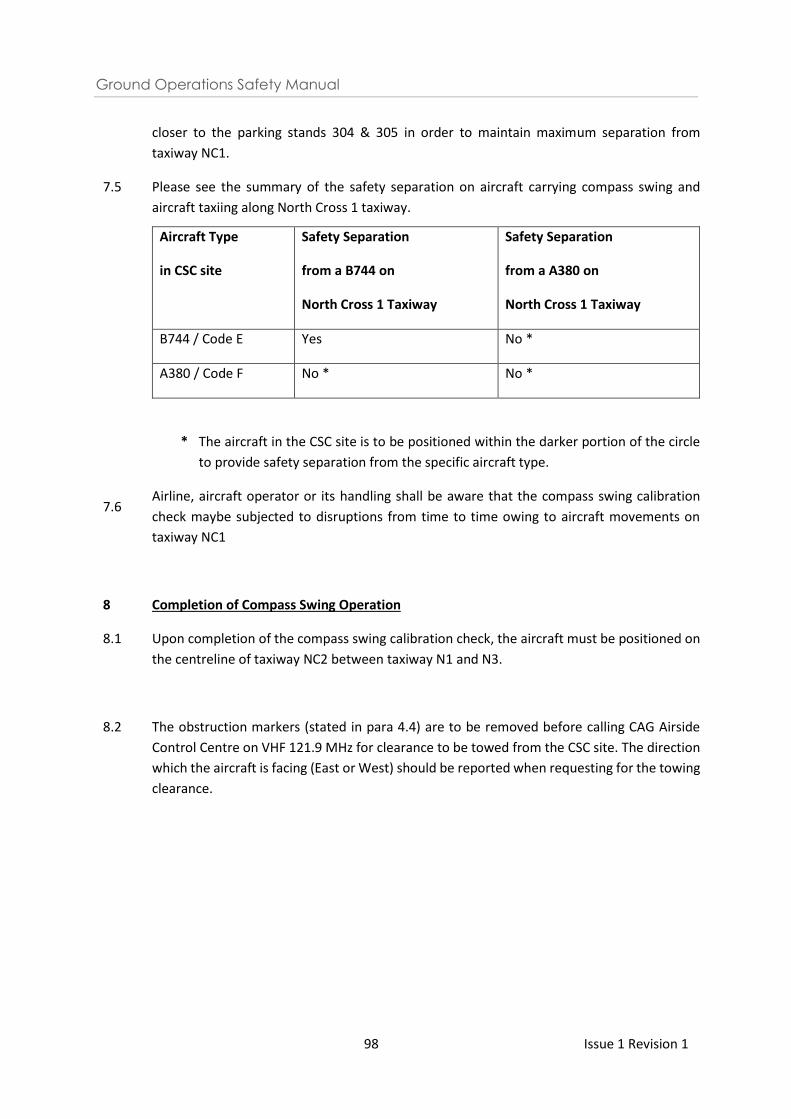
Ground Operations Safety Manual
98 Issue 1 Revision 1
closer to the parking stands 304 & 305 in order to maintain maximum separation from
taxiway NC1.
7.5 Please see the summary of the safety separation on aircraft carrying compass swing and
aircraft taxiing along North Cross 1 taxiway.
7.6
Aircraft Type
in CSC site
Safety Separation
from a B744 on
North Cross 1 Taxiway
Safety Separation
from a A380 on
North Cross 1 Taxiway
B744 / Code E Yes No *
A380 / Code F No * No *
* The aircraft in the CSC site is to be positioned within the darker portion of the circle
to provide safety separation from the specific aircraft type.
Airline, aircraft operator or its handling shall be aware that the compass swing calibration
check maybe subjected to disruptions from time to time owing to aircraft movements on
taxiway NC1
8 Completion of Compass Swing Operation
8.1 Upon completion of the compass swing calibration check, the aircraft must be positioned on
the centreline of taxiway NC2 between taxiway N1 and N3.
8.2 The obstruction markers (stated in para 4.4) are to be removed before calling CAG Airside
Control Centre on VHF 121.9 MHz for clearance to be towed from the CSC site. The direction
which the aircraft is facing (East or West) should be reported when requesting for the towing
clearance.
Ground Operations Safety Manual
99 Issue 1 Revision 1
ANNEX V
GENERAL GUIDELINES ON WASHING OF AIRCRAFT EXTERIORS IN
CHANGI AIRPORT 1 Washing of Aircraft Exteriors in Changi Airport
1.1 Washing of aircraft exteriors is allowed at aircraft stands fitted with grease / oil
separators. The stands are:
(c) Cargo stands
• 205 / 206 / 207 / 208 / 209
• 461 / 462 / 463 / 464 / 465 / 466 / 467 / 468 / 469 / 481 / 482 / 483 / 484 / 485 / 486 / 487
• 503 / 504 / 505 / 506 / 507 / 508
• 510 / 511 / 512 / 513 / 514 / 515 / 516 / 517
• 600 / 605
(d) At T3 and T4 respectively, the washing of aircraft (exterior) is subject to the following
conditions:
i. Allowed only at A3 (up to B744), A4 (up to A380, B773 & ER), A16 (Up to
B744), A17 (up to B744), A18 (up to B772), A19 (up to B772), B3 (up to B744), B4 (up
to A380, B773 & ER), G18 and G19;
ii. Only between 0100-0500 LT;
iii. Strictly no washing if the adjacent stand is occupied by an active aircraft with
passengers (minus 100 min from STD);
iv. To inform CAG Airside Control Centre before wash, providing details such as
the aircraft type / registration and stand number and expected duration of activity;
and
v. If the aircraft stand is found to be in an unsatisfactory condition after aircraft
wash, CAG shall engage a cleaning contractor to clean the aircraft stand and charge
the airline/ground handlers accordingly.
1.2 The washing of aircraft at aerobridge bays does not include T1 & T2.
1.3 The above shall apply in addition to the safety procedures of airlines/ ground
handlers.
1.4 The above is subject to review from time to time and CAG reserves the rights to
revoke / amend the conditions anytime with ample notice to the airline / ground handlers.
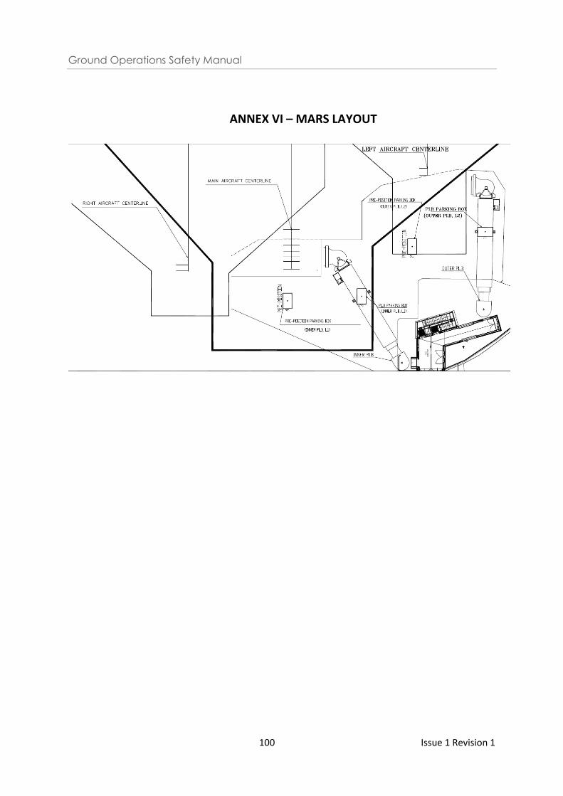
Ground Operations Safety Manual
100 Issue 1 Revision 1
ANNEX VI – MARS LAYOUT
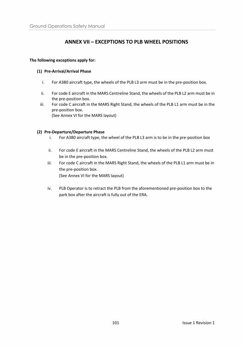
Ground Operations Safety Manual
101 Issue 1 Revision 1
ANNEX VII – EXCEPTIONS TO PLB WHEEL POSITIONS
The following exceptions apply for:
(1) Pre-Arrival/Arrival Phase
i. For A380 aircraft type, the wheels of the PLB L3 arm must be in the pre-position box.
ii. For code E aircraft in the MARS Centreline Stand, the wheels of the PLB L2 arm must be in the pre-position box.
iii. For code C aircraft in the MARS Right Stand, the wheels of the PLB L1 arm must be in the pre-position box. (See Annex VI for the MARS layout)
(2) Pre-Departure/Departure Phase i. For A380 aircraft type, the wheel of the PLB L3 arm is to be in the pre-position box
ii. For code E aircraft in the MARS Centreline Stand, the wheels of the PLB L2 arm must
be in the pre-position box.
iii. For code C aircraft in the MARS Right Stand, the wheels of the PLB L1 arm must be in
the pre-position box.
(See Annex VI for the MARS layout)
iv. PLB Operator is to retract the PLB from the aforementioned pre-position box to the
park box after the aircraft is fully out of the ERA.
Recommended