Grade Control Design BackgroundTwo Basic Types of Grade Control Structures1. Invert hard point to resist
erosion/degradation2. Hydraulic control
generating water surface upstream
Design Overview – Optimizing Hydraulics & Economics• Location• Type of structure• Locations• Spacing and net drop height – key design assessment
• Other factors

Grade Control Key Design Element for Environmentally Limited Solutions
Grade Control Structures Benefits• Mitigation measure for hydromodification• Preventing erosion of existing structures• Protection of alluvial streambed long term degradation
• Alternative to channel lining• Minimizing footprint impact in floodplain
Negative Aspects of Grade Control• Potential barrier to fish passage• Impact to environmental regulatory streambed• Public safety

Grade Control Design Process
• Hydraulics• Geomorphology• Fluvial Analysis
• Alternative Spacing• Drop Hydraulics/Sizing• Drop Heights
• Conceptual Locations• Alternative Systems• Local Adjustments
• Drop Structure Costs• Revised Channel Lining
Costs• Optimization
• Sediment• Mapping• Historical
Geomorphic Data

Baseline Technical Analysis Key Foundation for Engineering Design

GRADE CONTROL DESIGN CHARACTERISTICS
Grade Control Structure Alternative Design Variations

Grouted Rock Grade Control

Reinforced Concrete Grade Control
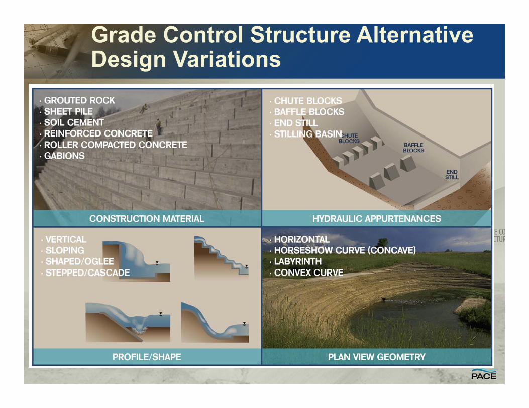
Gabion Grade Control
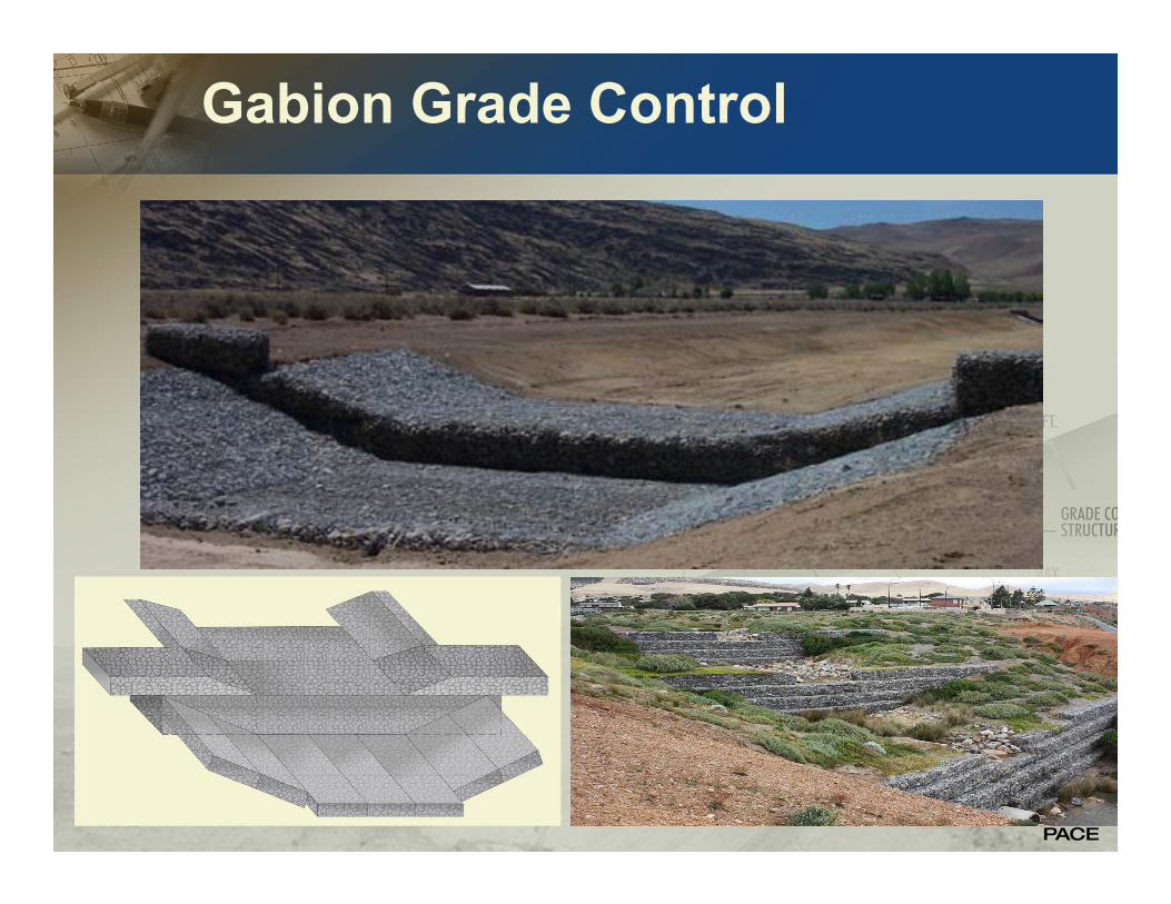
Sheet Pile Grade Control

Soil Cement / Roller Compacted Concrete Grade Control
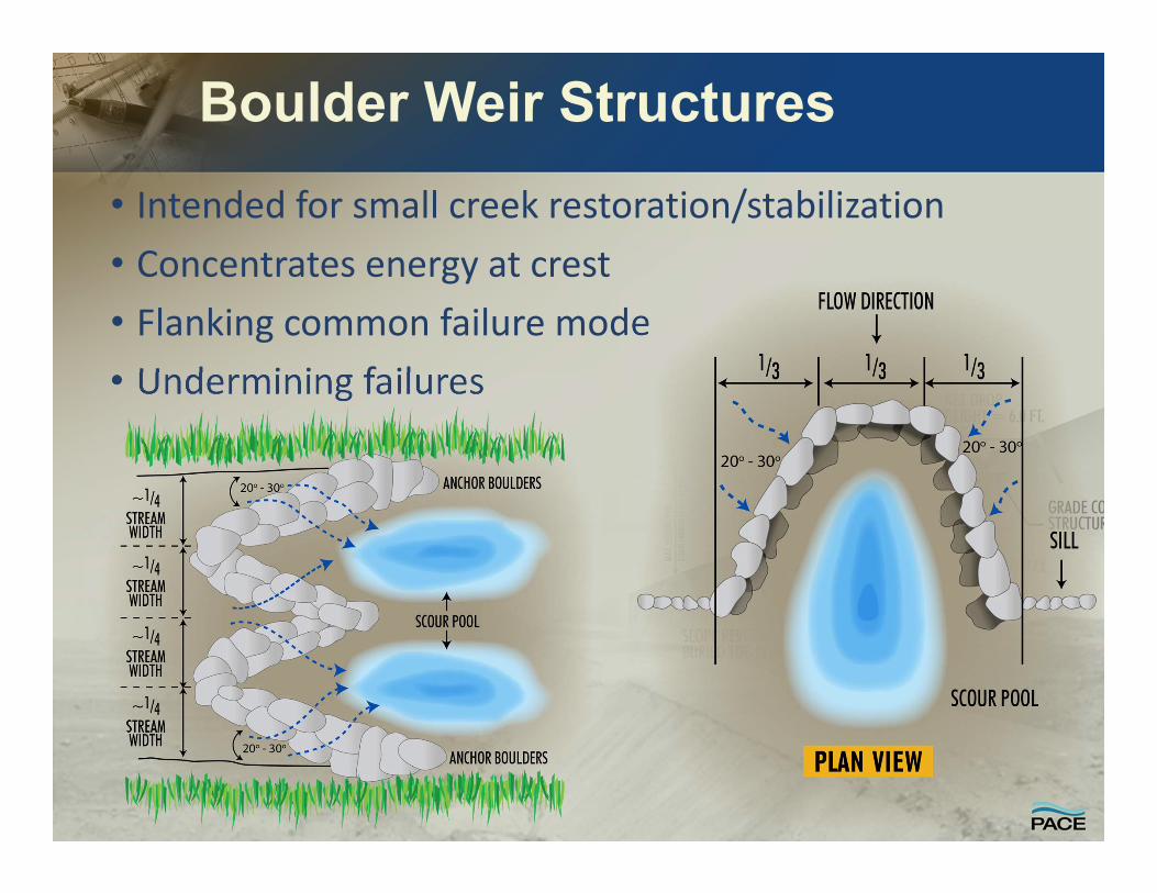
Boulder Weir Structures• Intended for small creek restoration/stabilization• Concentrates energy at crest • Flanking common failure mode• Undermining failures
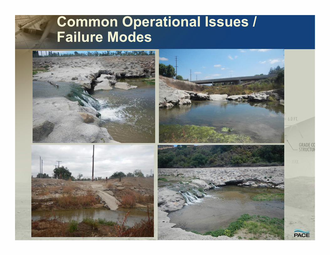
Common Operational Issues / Failure Modes

ENGINEERING DESIGN ANALYSIS OF GRADE CONTROL STRUCTURES
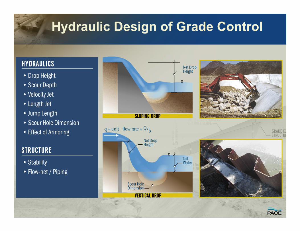
Hydraulic Design of Grade Control

Horizontal Spacing / Siting Grade Control Structures
• Spacing limited by equilibrium slope (Seq) and maximum allowable drop height (Hmax)
• Hmax governed by type of structure, hydraulic criteria, energy dissipation, structure stability/forces, costs, safety
Horizontal Spacing / Siting Grade Control Structures
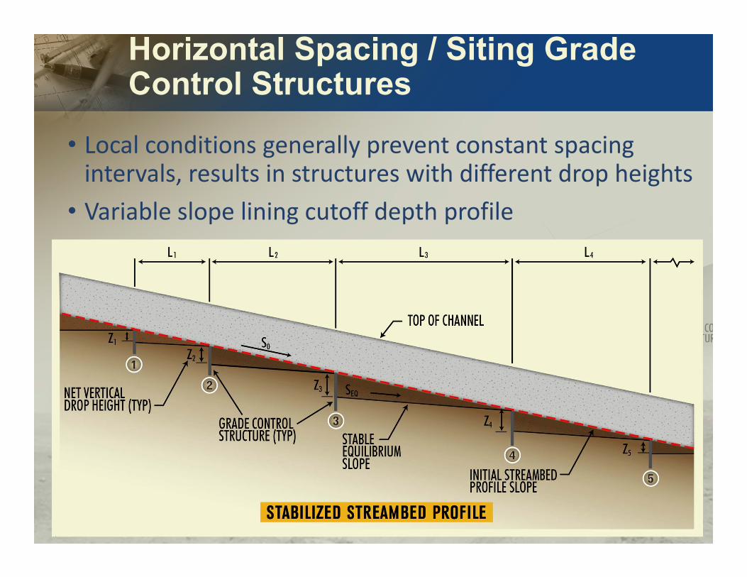
• Local conditions generally prevent constant spacing intervals, results in structures with different drop heights
• Variable slope lining cutoff depth profile

Drop Structure Spacing - Channel Equilibrium Slope Analysis
• Upstream sediment supply is a controlling factor assessing channel response.
• Balance of incoming sediment supply and transport capacity
• Application of multiple procedures since most difficult to reliably define
1. Geomorphic Procedures• Extrapolate historical trends2. Sediment Transport ‐ Empirical
Equilibrium Equations• Static equilibrium (incipient motion)• Dynamic equilibrium3. Sediment Balance/Continuity
Analysis4. Sediment Transport Modeling – Long
Term

Channel Equilibrium Slope Analysis – Empirical Equations
Incipient Motion
• Shields diagram and ∗ (
• Schoklitsch method L s bf3/4
• Meyer‐Peter Muller
L mpm bf s 901/6 3/2
Regime / Sediment Transport• Bray L 2
‐0.34450
0.58
• BUREC L 50 bf0.75
• Henderson L 901.15 –0.46
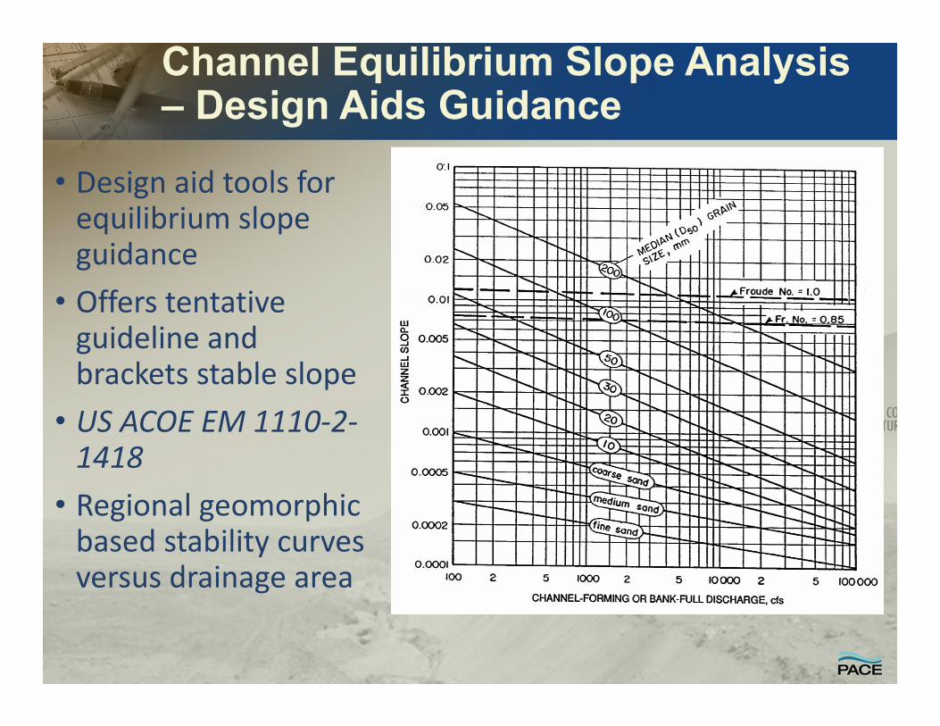
Channel Equilibrium Slope Analysis – Design Aids Guidance
• Design aid tools for equilibrium slope guidance
• Offers tentative guideline and brackets stable slope
• US ACOE EM 1110‐2‐1418
• Regional geomorphic based stability curves versus drainage area
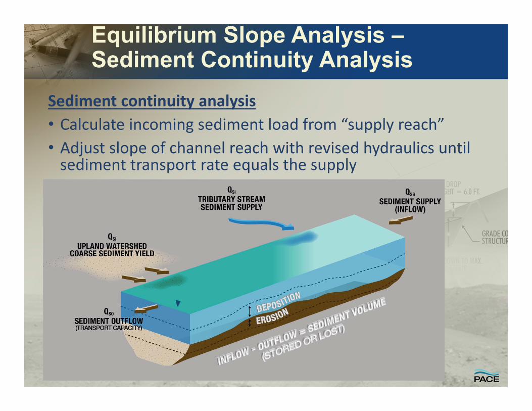
Equilibrium Slope Analysis –Sediment Continuity Analysis
Sediment continuity analysis • Calculate incoming sediment load from “supply reach”• Adjust slope of channel reach with revised hydraulics until sediment transport rate equals the supply
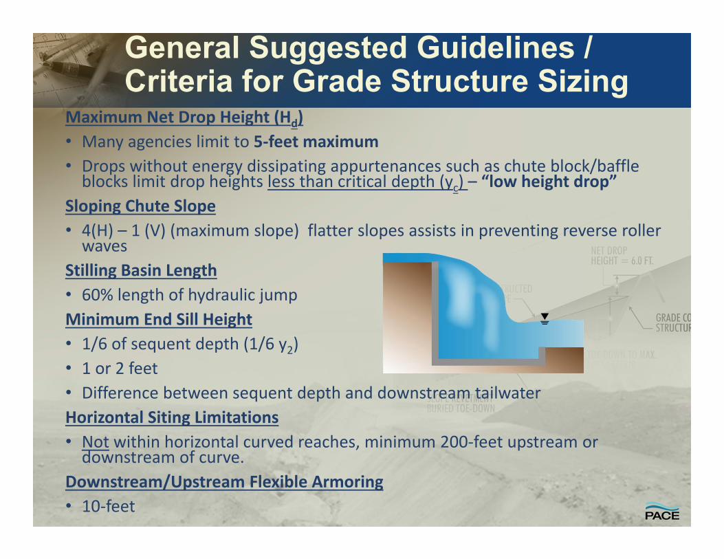
General Suggested Guidelines / Criteria for Grade Structure Sizing
Maximum Net Drop Height (Hd)• Many agencies limit to 5‐feet maximum• Drops without energy dissipating appurtenances such as chute block/baffle blocks limit drop heights less than critical depth (yc) – “low height drop”
Sloping Chute Slope• 4(H) – 1 (V) (maximum slope) flatter slopes assists in preventing reverse roller waves
Stilling Basin Length• 60% length of hydraulic jumpMinimum End Sill Height• 1/6 of sequent depth (1/6 y2)• 1 or 2 feet• Difference between sequent depth and downstream tailwaterHorizontal Siting Limitations• Not within horizontal curved reaches, minimum 200‐feet upstream or downstream of curve.
Downstream/Upstream Flexible Armoring• 10‐feet
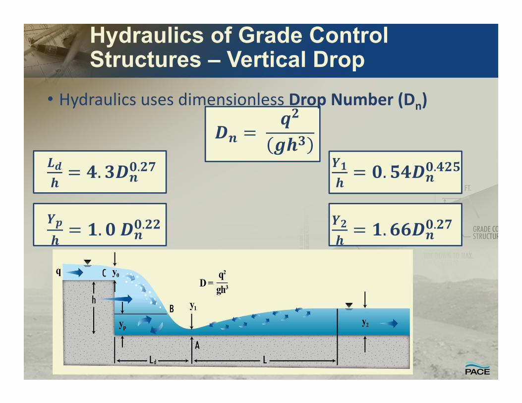
Hydraulics of Grade Control Structures – Vertical Drop
• Hydraulics uses dimensionless Drop Number (Dn)
. .
. .

Hydraulics of Grade Control Structures – Sloping Drop
• Follows hydraulics analysis procedures for stilling basin with Free Hydraulic Jump (trapezoidal or rectangular)
• HEC‐RAS not necessarily correctly calculating hydraulic losses / steep slope not accurate
1. Estimate total drop height includes initial estimate of sill height plus net drop height
2. Calculate depth at brink of chute (Yc)3. Calculate depth at base of chute (Y1) based on energy balance between top of chute ignoring energy losses
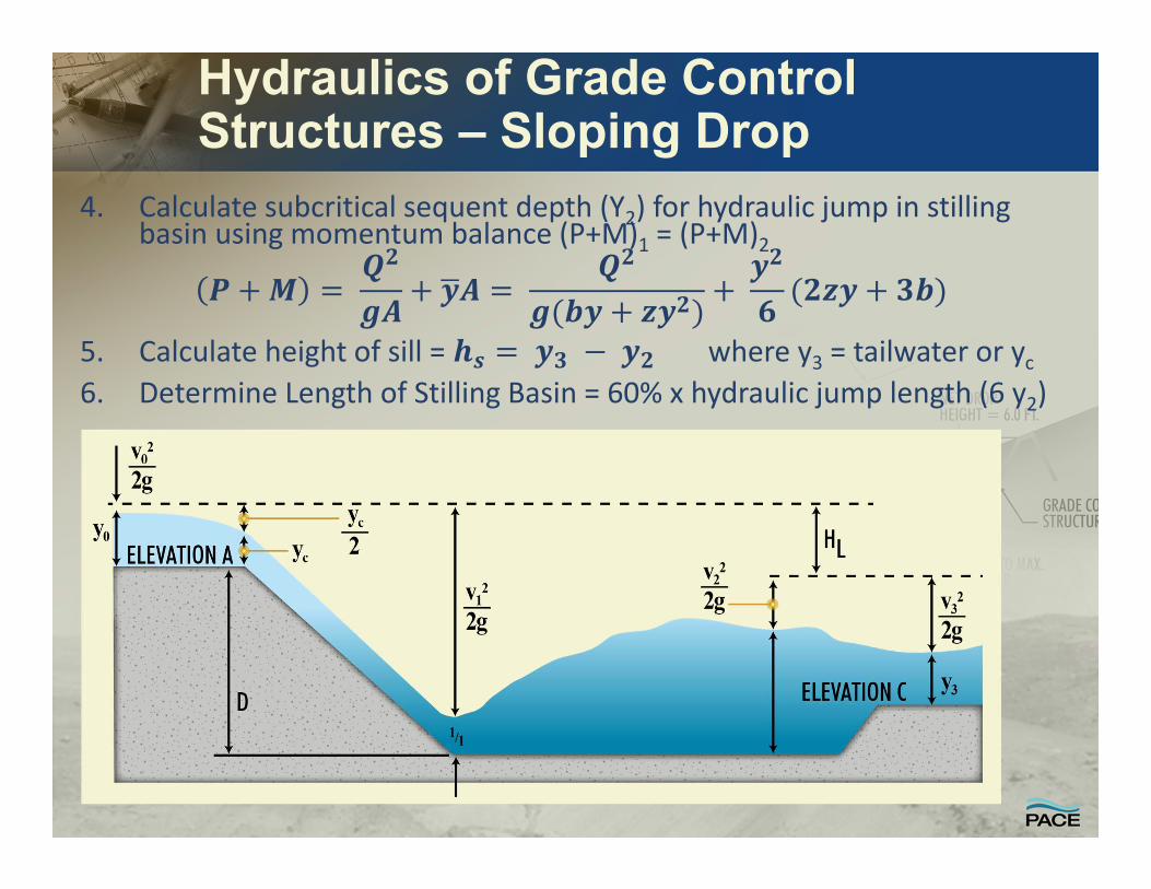
Hydraulics of Grade Control Structures – Sloping Drop
4. Calculate subcritical sequent depth (Y2) for hydraulic jump in stilling basin using momentum balance (P+M)1 = (P+M)2
5. Calculate height of sill = where y3 = tailwater or yc6. Determine Length of Stilling Basin = 60% x hydraulic jump length (6 y2)

Engineering Tool Hydraulic Analysis of Sloping Chute Drop Structures

Hydraulics of Grade Control Structures – Stepped Chute
• Hydraulics of stepped chute function of step height, step length, inclination/slope (h/L),and unit discharge (q)
• Results in either (1) nappe flow, (2) transition flow, and (3) skimming flow
Nappe Flow . / .
• Achieves 85‐95% energy dissipation total energy of drop
Skimming Flow• Develop uniform flow down chute because steps act as roughness elements
. .
. .
Where:
. /
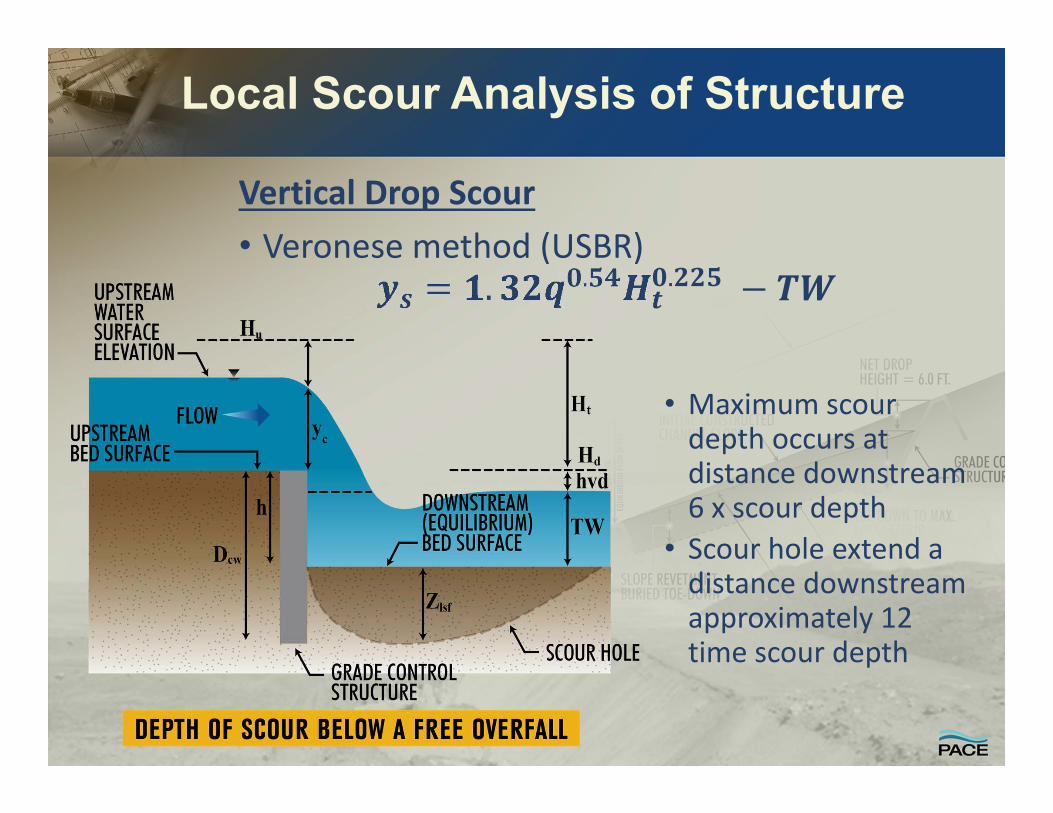
Local Scour Analysis of Structure
Vertical Drop Scour• Veronese method (USBR)
. .
• Maximum scour depth occurs at distance downstream 6 x scour depth
• Scour hole extend a distance downstream approximately 12 time scour depth
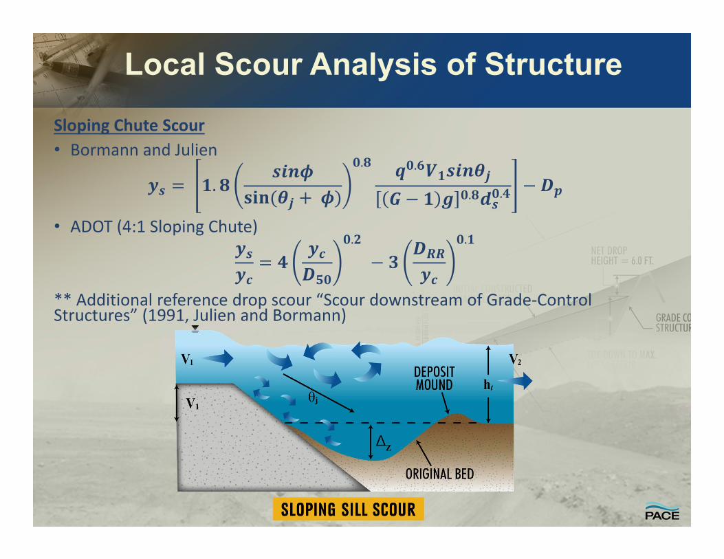
Local Scour Analysis of Structure
Sloping Chute Scour• Bormann and Julien
.
. .
. .
• ADOT (4:1 Sloping Chute).
.
** Additional reference drop scour “Scour downstream of Grade‐Control Structures” (1991, Julien and Bormann)
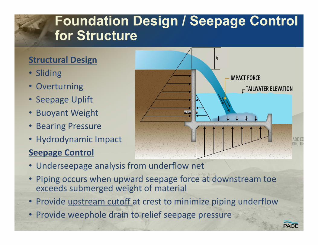
Foundation Design / Seepage Control for Structure
Structural Design• Sliding • Overturning• Seepage Uplift• Buoyant Weight• Bearing Pressure• Hydrodynamic ImpactSeepage Control• Underseepage analysis from underflow net• Piping occurs when upward seepage force at downstream toe exceeds submerged weight of material
• Provide upstream cutoff at crest to minimize piping underflow• Provide weephole drain to relief seepage pressure
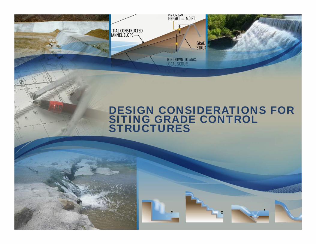
DESIGN CONSIDERATIONS FOR SITING GRADE CONTROL STRUCTURES

Critical Design Siting ConsiderationsHydraulic Considerations
• Stable channel hydraulicsGeotechnical Considerations
• Streambank Stability / FoundationFlood Control Impacts
• Local Drainage• Water Surface / Flood Protection Level
Environmental Considerations• Fish and Wildlife Passage Barrier
Safety Considerations• Drop Height• Vector Control
Physical Constraints / Limitations• Existing Utility• Local Drainage• Existing Channel Slope Lining• Existing Structures
Economics

Horizontal and Vertical Siting Economics Impacted by Existing Channel Lining
• Range of Drop Heights – Constant Spacing• Alternative Layouts Plan / Profile• Comparison to existing structure locations and channel profile
• Impacts to existing lining toedown and channel freeboard

• Cost considerations not only include drop structure construction but also modifications to channel slope lining
• Raising or lowering of channel slope lining impact siting of drop structures

AUTOMATED PLANNING DESIGN TOOL

Drop Structure Automated Design Alternative Planning Tool
• Drop Structure Alternative Assessment System Tool Development• Drop Height• Geometry / Construction Materials• Hydraulics Parameters• Scour• Structure Dimensions
• Results in Costs function of drop height• Additional costs (environmental/dewatering)
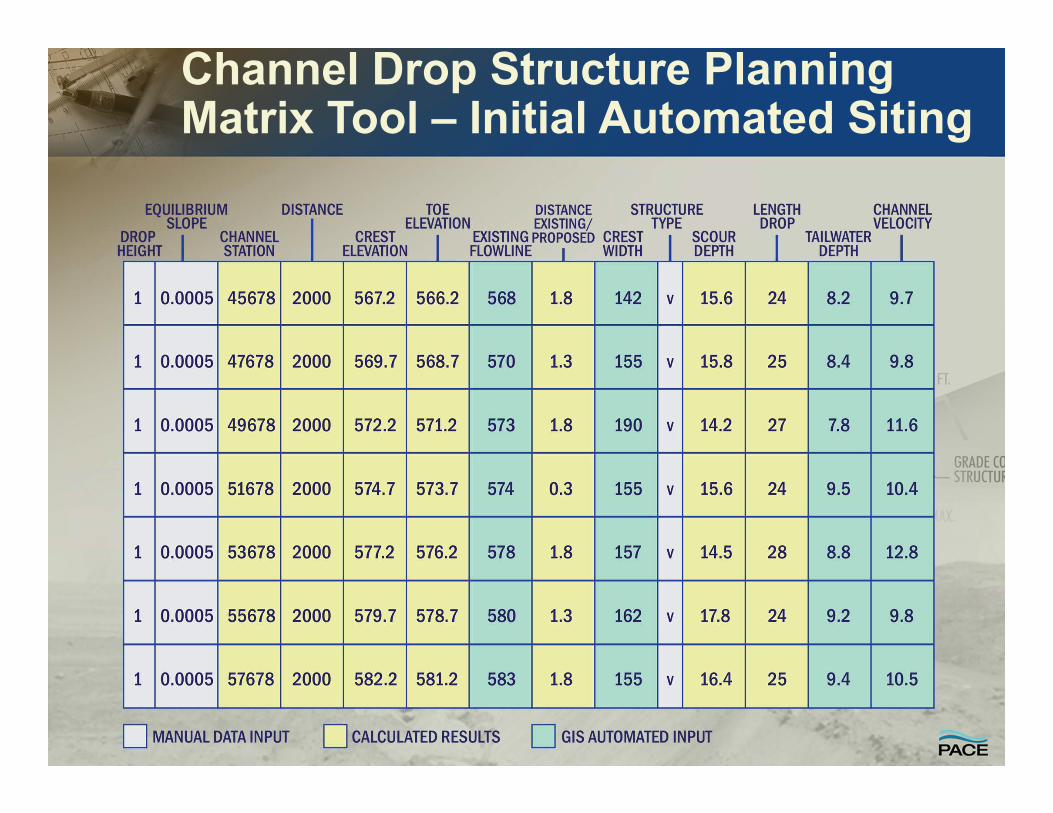
Channel Drop Structure Planning Matrix Tool – Initial Automated Siting

Automated Drop Structure Costs Calculation Tool – Drop Height/Type
• Two part planning tool for (1) drop hydraulics and (2) costs of facility
• Automated sizing of drop structure basics of “type” of structure, height, and channel dimensions
• Includes estimate of scour depth for drop type and height• Evaluate straight drop with and without stilling basins
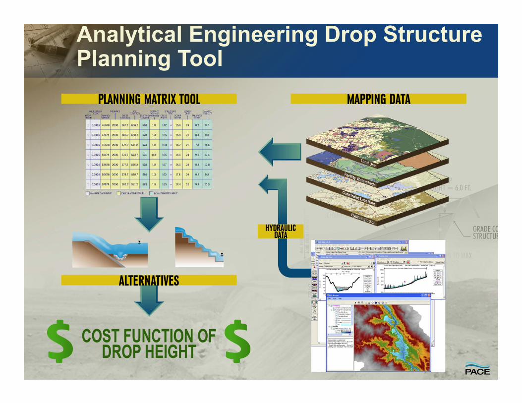
Analytical Engineering Drop Structure Planning Tool

Recommended