GPU-Accelerated Optical Coherence Tomography (OCT) Imaging
GPU Technology Conference 2012,
San Jose, California, May 16, 2012
Kang Zhang (Speaker)
Jin U. Kang
GE Global Research
General Electric Company
Department of Electrical and Computer Engineering
The Johns Hopkins University
Introduction to Optical Coherence Tomography (OCT)
GPU accelerated OCT imaging
Microsurgical Applications
Summary
Outline
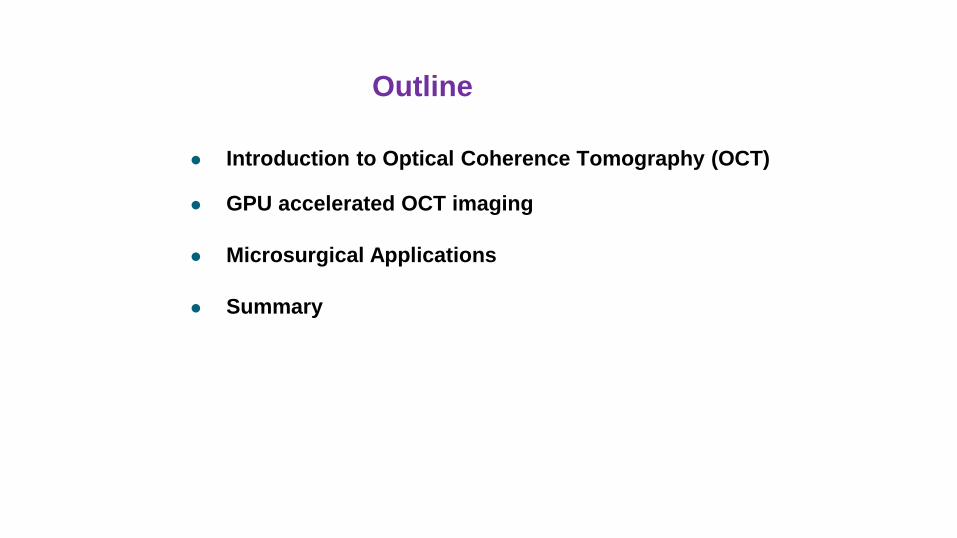
Operating Area
Tool Insertion Points
Tool
Typical Scenario of Vitreo-Retinal Surgery (Vitrectomy)
Surgical Tool
ILM
Imaging-Guided Microsurgical Intervention (IGMI)
Motivate
Real-Time ~µm level
Sensing and Imaging as feedback
Imaging
Distance Ranging
Motion Compensation
Device guidance / tracking
Tumor / blood vessel segmentation
0 100 200 300 400 500 0
5
10
15 x 10 4
Depth [um]
OC
T s
ignal [a
. u.]
d
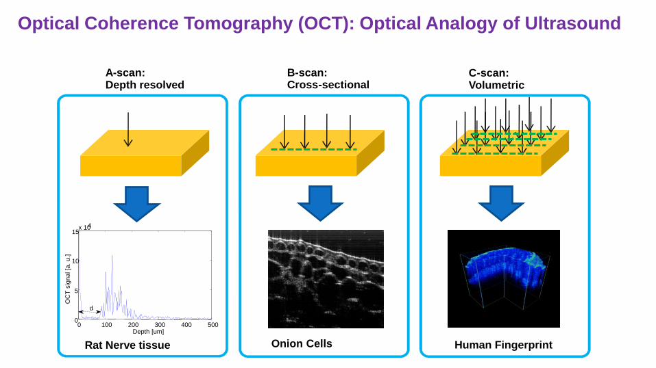
A - scan: Depth resolved
B - scan: Cross - sectional
C - scan: Volumetric
Onion Cells Human Fingerprint Rat Nerve tissue
Optical Coherence Tomography (OCT): Optical Analogy of Ultrasound
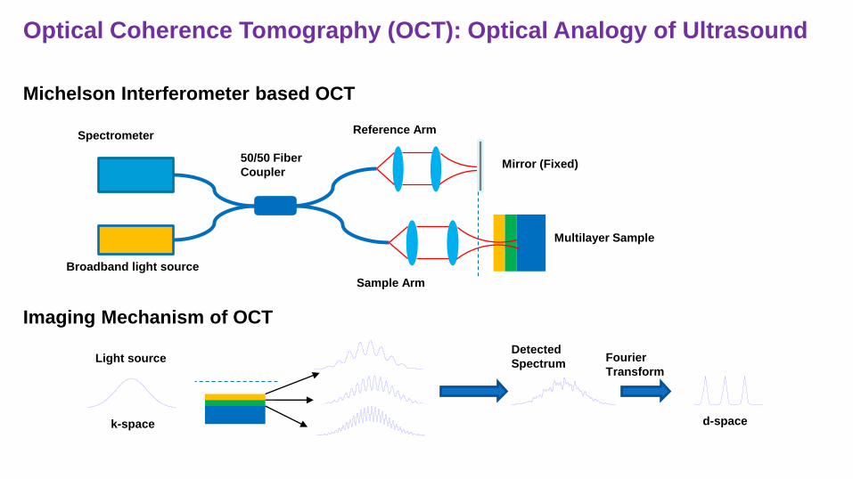
Broadband light source
50/50 Fiber
Coupler
Spectrometer
Multilayer Sample
Sample Arm
Mirror (Fixed)
Reference Arm
Detected
Spectrum Fourier
Transform
k-space d-space
Light source
Optical Coherence Tomography (OCT): Optical Analogy of Ultrasound
Michelson Interferometer based OCT
Imaging Mechanism of OCT
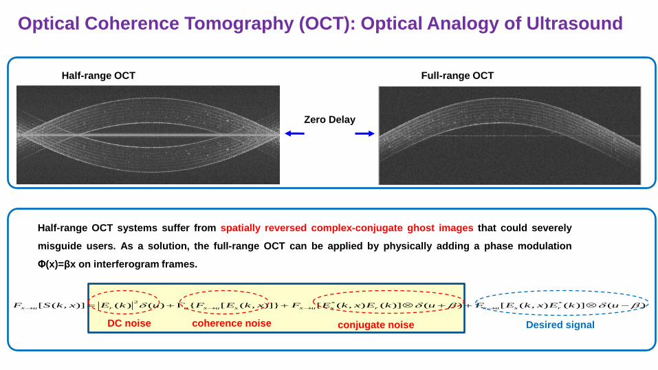
Half-range OCT systems suffer from spatially reversed complex-conjugate ghost images that could severely
misguide users. As a solution, the full-range OCT can be applied by physically adding a phase modulation
Φ(x)=βx on interferogram frames.
)()](),([)()](),([)]},([{)()()],([ **2 ukExkEFukExkEFxkEFukExkSF rsuxrsuxsuxurux
DC noise coherence noise conjugate noise Desired signal
Half-range OCT Full-range OCT
Zero Delay
Optical Coherence Tomography (OCT): Optical Analogy of Ultrasound
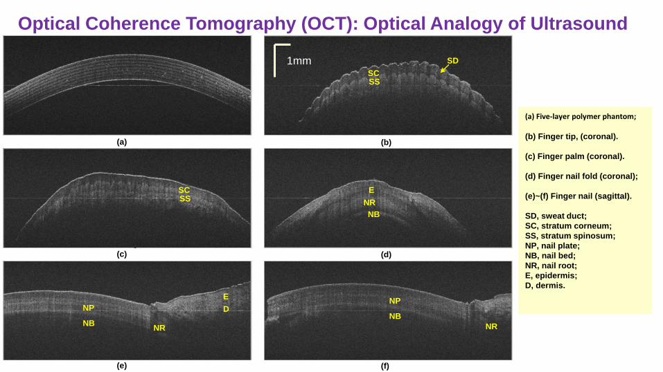
(a) Five-layer polymer phantom; (b) Finger tip, (coronal).
(c) Finger palm (coronal).
(d) Finger nail fold (coronal);
(e)~(f) Finger nail (sagittal).
SD, sweat duct;
SC, stratum corneum;
SS, stratum spinosum;
NP, nail plate;
NB, nail bed;
NR, nail root;
E, epidermis;
D, dermis.
(a)
(c) (d)
(e)
SS SC
NR
NB
E
NP
NB NR
E
D
(f)
NP
NB
NR
(b)
SS SC
SD 1mm
Optical Coherence Tomography (OCT): Optical Analogy of Ultrasound
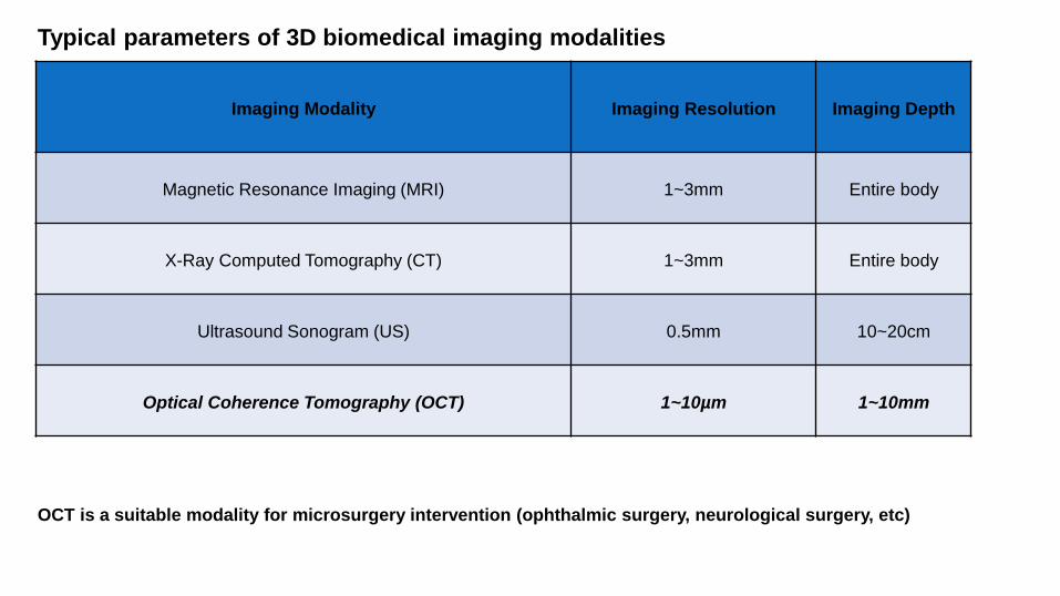
Imaging Modality Imaging Resolution Imaging Depth
Magnetic Resonance Imaging (MRI) 1~3mm Entire body
X-Ray Computed Tomography (CT) 1~3mm Entire body
Ultrasound Sonogram (US) 0.5mm 10~20cm
Optical Coherence Tomography (OCT) 1~10µm 1~10mm
Typical parameters of 3D biomedical imaging modalities
OCT is a suitable modality for microsurgery intervention (ophthalmic surgery, neurological surgery, etc)
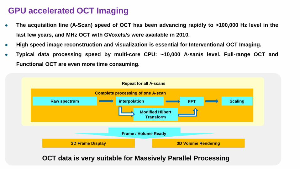
The acquisition line (A-Scan) speed of OCT has been advancing rapidly to >100,000 Hz level in the
last few years, and MHz OCT with GVoxels/s were available in 2010.
High speed image reconstruction and visualization is essential for Interventional OCT Imaging.
Typical data processing speed by multi-core CPU: ~10,000 A-san/s level. Full-range OCT and
Functional OCT are even more time consuming.
GPU accelerated OCT Imaging
FFT Raw spectrum Scaling interpolation
Complete processing of one A-scan
2D Frame Display
Modified Hilbert
Transform
3D Volume Rendering
Repeat for all A-scans
Frame / Volume Ready
OCT data is very suitable for Massively Parallel Processing
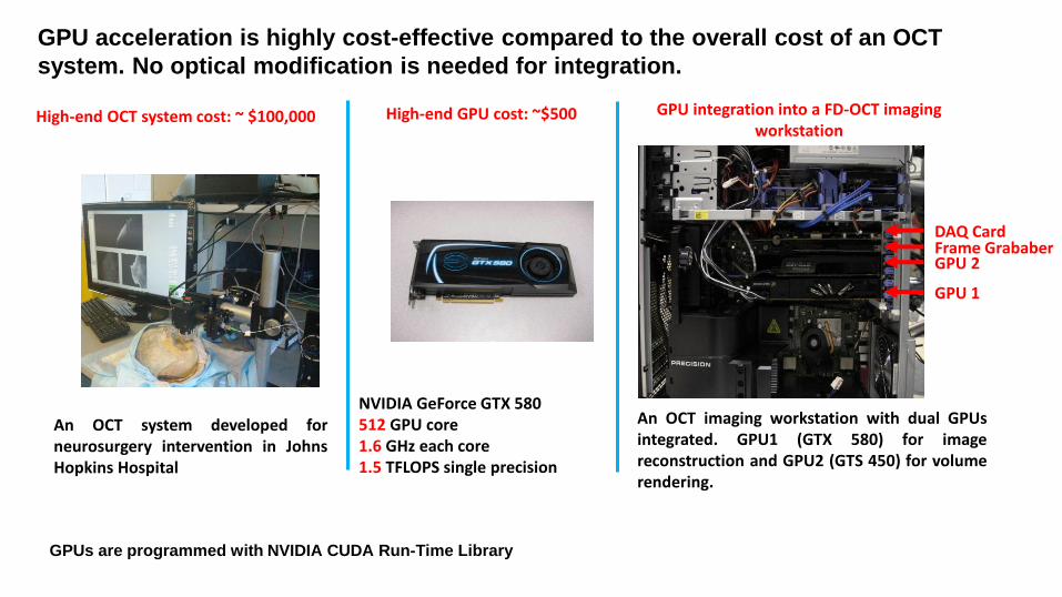
High-end OCT system cost: ~ $100,000
NVIDIA GeForce GTX 580 512 GPU core 1.6 GHz each core 1.5 TFLOPS single precision
High-end GPU cost: ~$500
GPU 2
GPU 1
Frame Grababer DAQ Card
An OCT system developed for neurosurgery intervention in Johns Hopkins Hospital
GPU integration into a FD-OCT imaging workstation
An OCT imaging workstation with dual GPUs integrated. GPU1 (GTX 580) for image reconstruction and GPU2 (GTS 450) for volume rendering.
GPU acceleration is highly cost-effective compared to the overall cost of an OCT
system. No optical modification is needed for integration.
GPUs are programmed with NVIDIA CUDA Run-Time Library
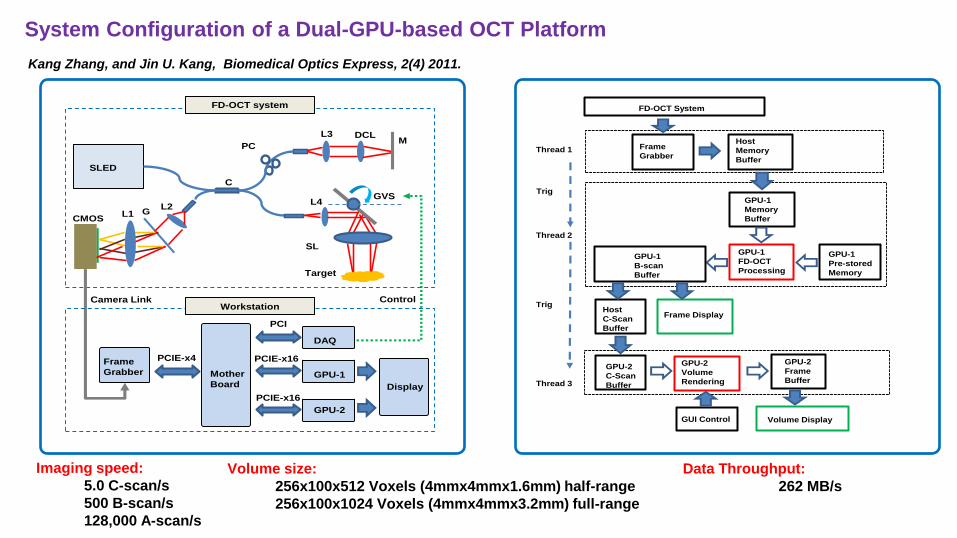
System Configuration of a Dual-GPU-based OCT Platform
SLED
C
PC
L3
L1 GCMOS
Camera Link
L2
DCL
SL
L4GVS
M
Target
Mother
Board
Frame
Grabber
DAQ
GPU-1
GPU-2
Display
PCI
PCIE-x16
PCIE-x16
PCIE-x4
FD-OCT system
WorkstationControl
Thread 1
Thread 2
Thread 3
Frame
Grabber
Host
Memory
Buffer
GPU-1
Memory
Buffer
GPU-1
Pre-stored
Memory
GPU-1
FD-OCT
Processing
GPU-1
B-scan
Buffer
Host
C-Scan
Buffer
GPU-2
Volume
Rendering
GPU-2
Frame
Buffer
Trig
Trig
FD-OCT System
GPU-2
C-Scan
Buffer
Frame Display
Volume DisplayGUI Control
Kang Zhang, and Jin U. Kang, Biomedical Optics Express, 2(4) 2011.
Imaging speed:
5.0 C-scan/s
500 B-scan/s
128,000 A-scan/s
Volume size:
256x100x512 Voxels (4mmx4mmx1.6mm) half-range
256x100x1024 Voxels (4mmx4mmx3.2mm) full-range
Data Throughput:
262 MB/s
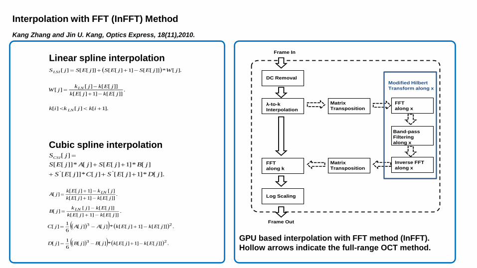
Interpolation with FFT (InFFT) Method
].[*]][[]1][[]][[][ jWjESjESjESjSLSI
Linear spline interpolation
Cubic spline interpolation
.]][[]1][[
]][[][][
jEkjEk
jEkjkjW LN
].1[][][ ikjkik LN
].[*]1][[][*]][[
][*]1][[][*]][[
][
"" jDjESjCjES
jBjESjAjES
jSCSI
.]][[]1][[
][]1][[][
jEkjEk
jkjEkjA LN
.]][[]1][[
]][[][][
jEkjEk
jEkjkjB LN
.]][[]1][[*][][6
1][
23jEkjEkjAjAjC
.]][[]1][[*][][6
1][
23jEkjEkjBjBjD
λ-to-k
Interpolation
FFT
along k
FFT
along x
Inverse FFT
along x
Band-pass
Filtering
along x
Matrix
Transposition
Matrix
Transposition
DC Removal
Log Scaling
Frame In
Frame Out
Modified Hilbert
Transform along x
GPU based interpolation with FFT method (InFFT).
Hollow arrows indicate the full-range OCT method.
Kang Zhang and Jin U. Kang, Optics Express, 18(11),2010.
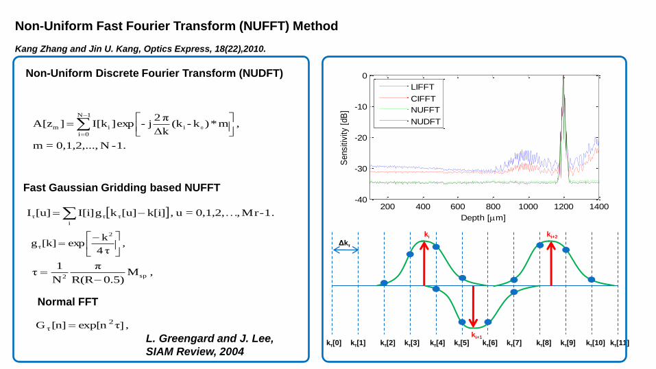
Kang Zhang and Jin U. Kang, Optics Express, 18(22),2010.
Fast Gaussian Gridding based NUFFT
Normal FFT
1.-N0,1,2,...,=m
, m*)k-(kΔk
π2j-exp]I[k]A[z
0i
1N
0i
im
Non-Uniform Discrete Fourier Transform (NUDFT)
. 1-Mr,…0,1,2,=u , k[i][u]kgI[i][u]Ii
τττ
, τ4
kexp[k]g
2
τ
, M0.5)R(R
π
N
1τ sp2
, τ]exp[n[n]G 2τ
L. Greengard and J. Lee,
SIAM Review, 2004
200 400 600 800 1000 1200 1400-40
-30
-20
-10
0
Depth [m]
Sensitiv
ity [
dB
]
LIFFT
CIFFT
NUFFT
NUDFT
Δkτ
ki
ki+1
ki+2
kτ[0] kτ[1] kτ[2] kτ[3] kτ[4] kτ[5] kτ[6] kτ[7] kτ[8] kτ[9] kτ[10] kτ[11]
Non-Uniform Fast Fourier Transform (NUFFT) Method
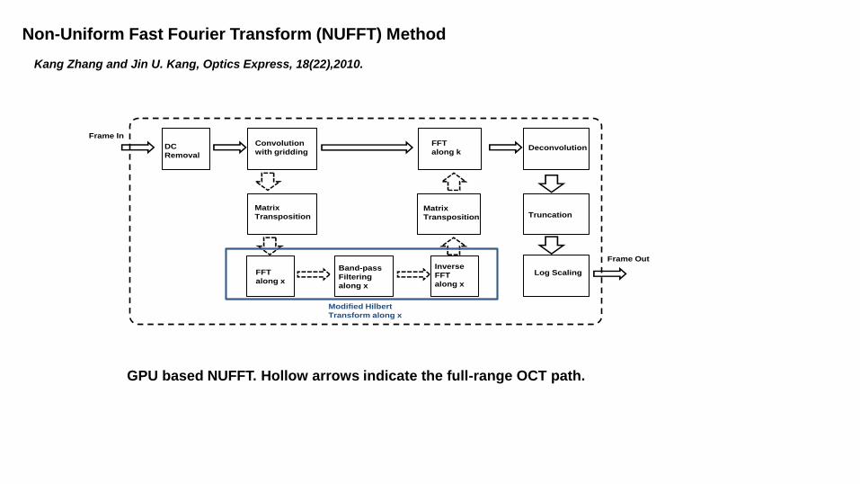
Convolution
with gridding
FFT
along k
FFT
along x
Inverse
FFT
along x
Band-pass
Filtering
along x
Matrix
Transposition
Deconvolution
Matrix
Transposition
DC
Removal
Truncation
Log Scaling
Frame In
Frame Out
Modified Hilbert
Transform along x
GPU based NUFFT. Hollow arrows indicate the full-range OCT path.
Kang Zhang and Jin U. Kang, Optics Express, 18(22),2010.
Non-Uniform Fast Fourier Transform (NUFFT) Method
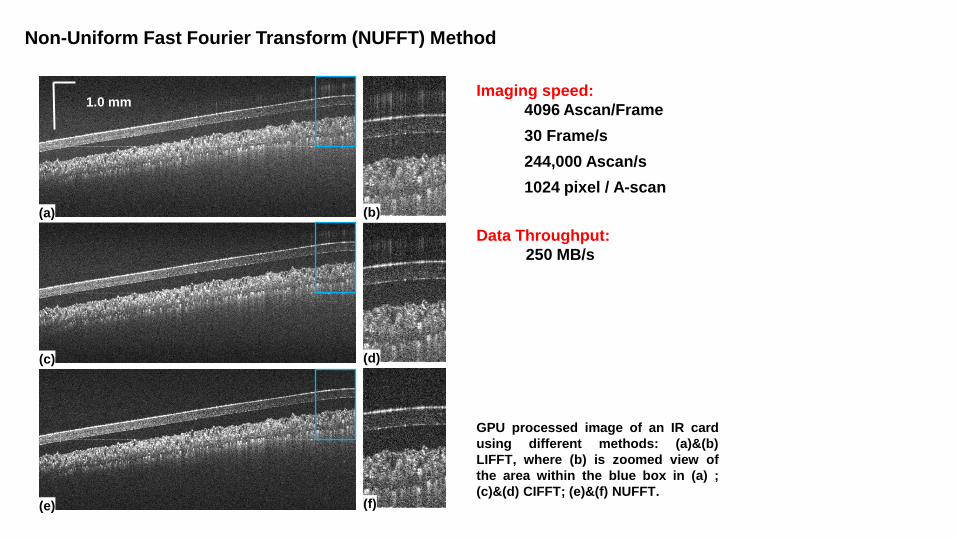
(a)
(c)
(e)
(b)
(d)
(f)
1.0 mm
GPU processed image of an IR card
using different methods: (a)&(b)
LIFFT, where (b) is zoomed view of
the area within the blue box in (a) ;
(c)&(d) CIFFT; (e)&(f) NUFFT.
Imaging speed:
4096 Ascan/Frame
30 Frame/s
244,000 Ascan/s
1024 pixel / A-scan
Data Throughput:
250 MB/s
Non-Uniform Fast Fourier Transform (NUFFT) Method
Broadband light source
50/50 Fiber
Coupler
Spectrometer
Multilayer
Sample
Sample Arm
Mirror (Fixed)
Reference
Arm
(c)
100 150 200 250 300 350 400
0.2
0.4
0.6
0.8
1
Depth [µm]
Inte
nsity
[a.
u.
]
Dispersion Compensated
Original
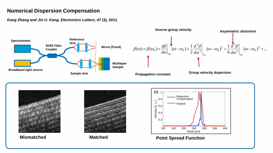
Mismatched Matched Point Spread Function
...)(6
1)(
2
1)()()( 3
03
32
02
2
00
000
d
d
d
d
d
d
Propagation constant
Inverse group velocity
Group velocity dispersion
Asymmetric distortion
Numerical Dispersion Compensation
Kang Zhang and Jin U. Kang, Electronics Letters, 47 (3), 2011.
303
2
02 ωωaωωaΦ
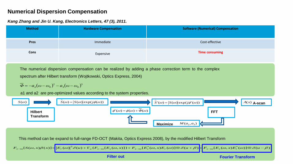
The numerical dispersion compensation can be realized by adding a phase correction term to the complex
spectrum after Hilbert transform (Wojtkowski, Optics Express, 2004)
a1 and a2 are pre-optimized values according to the system properties.
)(S ))(exp()()( jSS
)()()(' ΦHilbert
Transform
))('exp()()(' jSS
Maximize
)(xA A-scan
),( 32 aaM
FFT
This method can be expand to full-range FD-OCT (Makita, Optics Express 2008), by the modified Hilbert Transform
)()](),([)()](),([)]},([{)()()](),([ **2 uExEFuExEFxEFuExxSF rsuxrsuxsuxurux
Method Hardware Compensation
Software (Numerical) Compensation
Pros Immediate Cost-effective
Cons Expensive Time consuming
Filter out Fourier Transform
Numerical Dispersion Compensation
Kang Zhang and Jin U. Kang, Electronics Letters, 47 (3), 2011.
λ-to-k
Interpolation
Phase
Correction
FFT
along x
Inverse
FFT
along x
Band-pass
Filtering
along x
Matrix
Transposition
Matrix
Transposition
DC
Removal
Log
Scaling
Frame In
Frame Out
FFT
along k
Inverse
FFT
along k
Heaviside
step
Filtering
along k
Complex
Spectrum
Modified Hilbert
Transform along x
Hilbert Transform
along k
FFT
along k
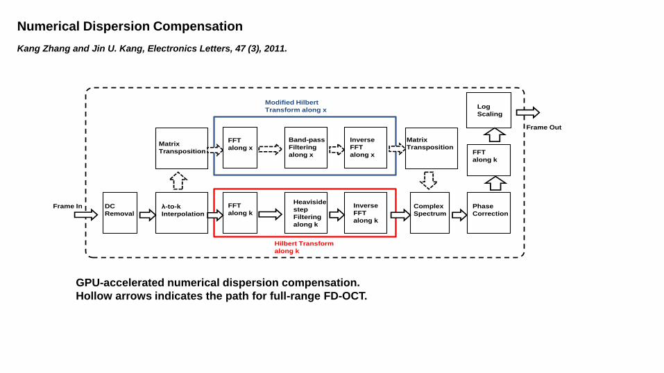
GPU-accelerated numerical dispersion compensation.
Hollow arrows indicates the path for full-range FD-OCT.
Numerical Dispersion Compensation
Kang Zhang and Jin U. Kang, Electronics Letters, 47 (3), 2011.
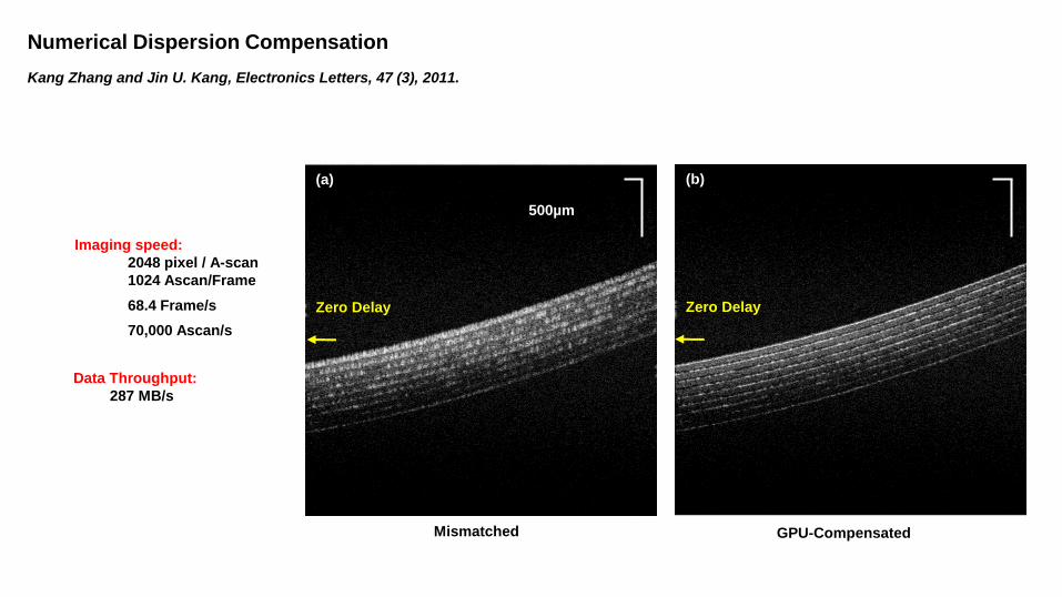
(a)
Zero Delay
(b)
Zero Delay
500µm
Data Throughput:
287 MB/s
Imaging speed:
2048 pixel / A-scan
1024 Ascan/Frame
68.4 Frame/s
70,000 Ascan/s
Mismatched GPU-Compensated
Numerical Dispersion Compensation
Kang Zhang and Jin U. Kang, Electronics Letters, 47 (3), 2011.
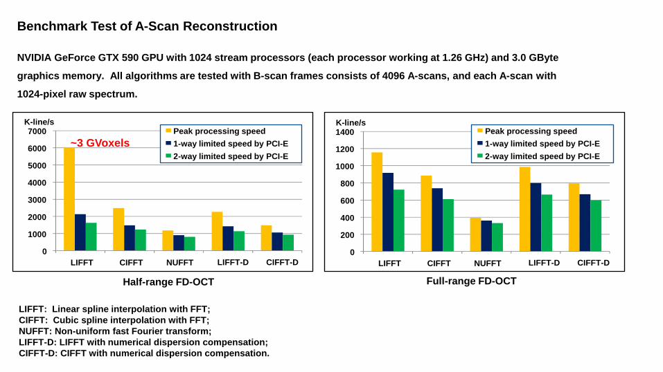
NVIDIA GeForce GTX 590 GPU with 1024 stream processors (each processor working at 1.26 GHz) and 3.0 GByte
graphics memory. All algorithms are tested with B-scan frames consists of 4096 A-scans, and each A-scan with
1024-pixel raw spectrum.
LIFFT: Linear spline interpolation with FFT;
CIFFT: Cubic spline interpolation with FFT;
NUFFT: Non-uniform fast Fourier transform;
LIFFT-D: LIFFT with numerical dispersion compensation;
CIFFT-D: CIFFT with numerical dispersion compensation.
0
1000
2000
3000
4000
5000
6000
7000
LIFFT CIFFT NUFFT LIFFT-D CIFFT-D
0
200
400
600
800
1000
1200
1400
LIFFT CIFFT NUFFT
Peak processing speed
1 - way limited speed by PCI-E
2 - way limited speed by PCI-E
Peak processing speed
1 - way limited speed by PCI-E
2 - way limited speed by PCI-E
LIFFT-D CIFFT-D
K-line/s K-line/s
Half-range FD-OCT Full-range FD-OCT
~3 GVoxels
Benchmark Test of A-Scan Reconstruction
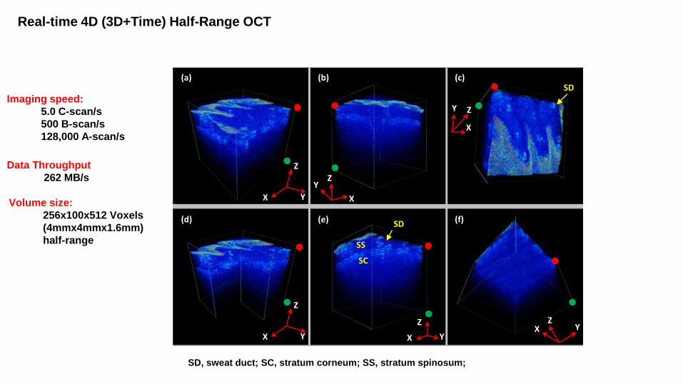
Real-time 4D (3D+Time) Half-Range OCT
(a) (b) (c)
(d) (e) (f)
Z
Y X
Z Y
X
Z
Y X
Z Y X
Z
Y X
Z Y
X
SD
SD
SS
SC
SD, sweat duct; SC, stratum corneum; SS, stratum spinosum;
Imaging speed:
5.0 C-scan/s
500 B-scan/s
128,000 A-scan/s
Volume size:
256x100x512 Voxels
(4mmx4mmx1.6mm)
half-range
Data Throughput
262 MB/s
(a) (b) (c)
(d) (e) (f)
Z
Y X
Z Y
X
Z
Y X
Z Y X
Z
Y X
Z Y
X
E
D
NP
NB
NR
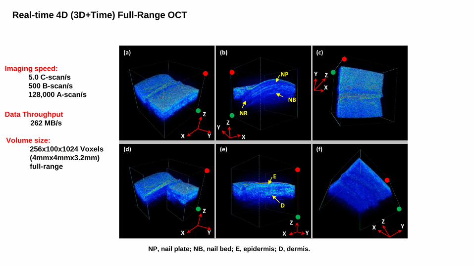
NP, nail plate; NB, nail bed; E, epidermis; D, dermis.
Imaging speed:
5.0 C-scan/s
500 B-scan/s
128,000 A-scan/s
Volume size:
256x100x1024 Voxels
(4mmx4mmx3.2mm)
full-range
Data Throughput
262 MB/s
Real-time 4D (3D+Time) Full-Range OCT
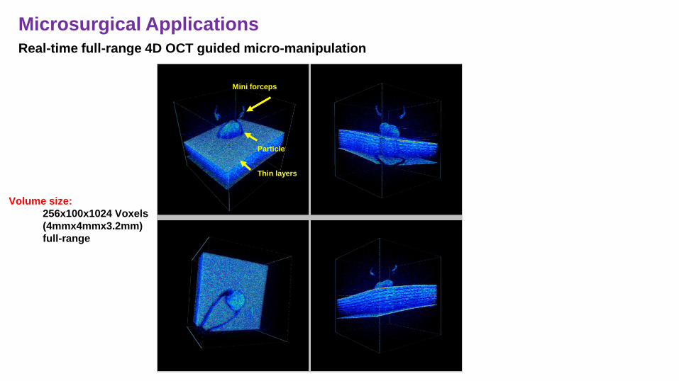
Particle
Thin layers
Mini forceps
Real-time full-range 4D OCT guided micro-manipulation
Microsurgical Applications
Volume size:
256x100x1024 Voxels
(4mmx4mmx3.2mm)
full-range
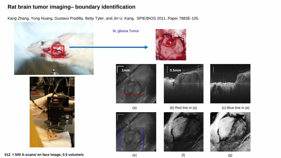
Rat brain tumor imaging– boundary identification
Kang Zhang, Yong Huang, Gustavo Pradilla, Betty Tyler, and Jin U. Kang, SPIE/BIOS 2011, Paper 7883E-105.
9L glioma Tumor
(a) (b) Red line in (a) (c) Blue line in (a)
(e) (f) (g)
1mm 0.5mm
512 ×500 A-scans/ en face image, 0.5 volume/s
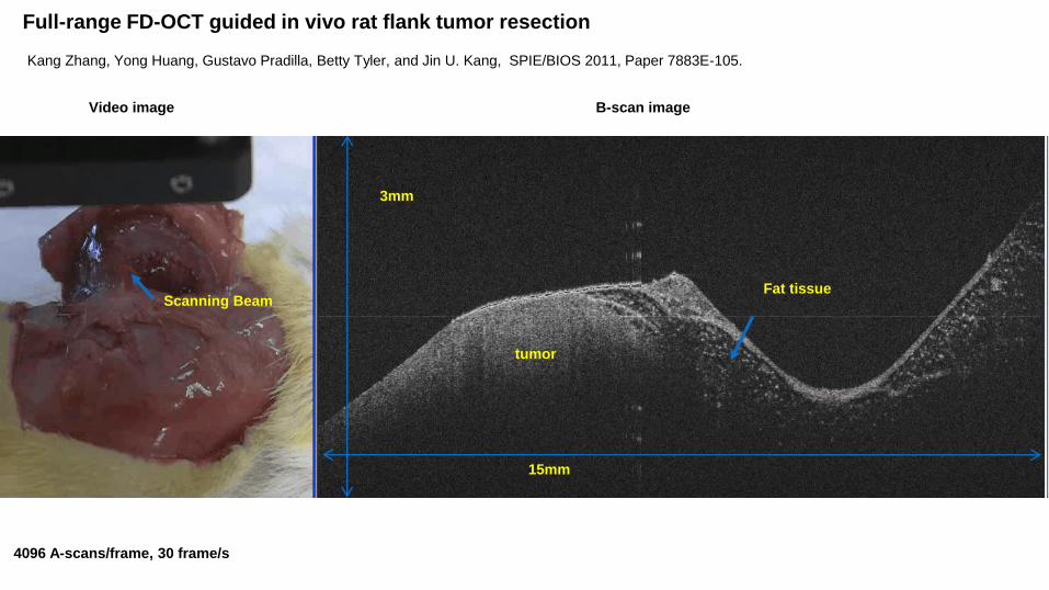
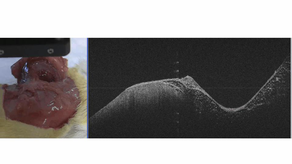
Full-range FD-OCT guided in vivo rat flank tumor resection
tumor
Fat tissue Scanning Beam
Video image B-scan image
3mm
15mm
4096 A-scans/frame, 30 frame/s
Kang Zhang, Yong Huang, Gustavo Pradilla, Betty Tyler, and Jin U. Kang, SPIE/BIOS 2011, Paper 7883E-105.
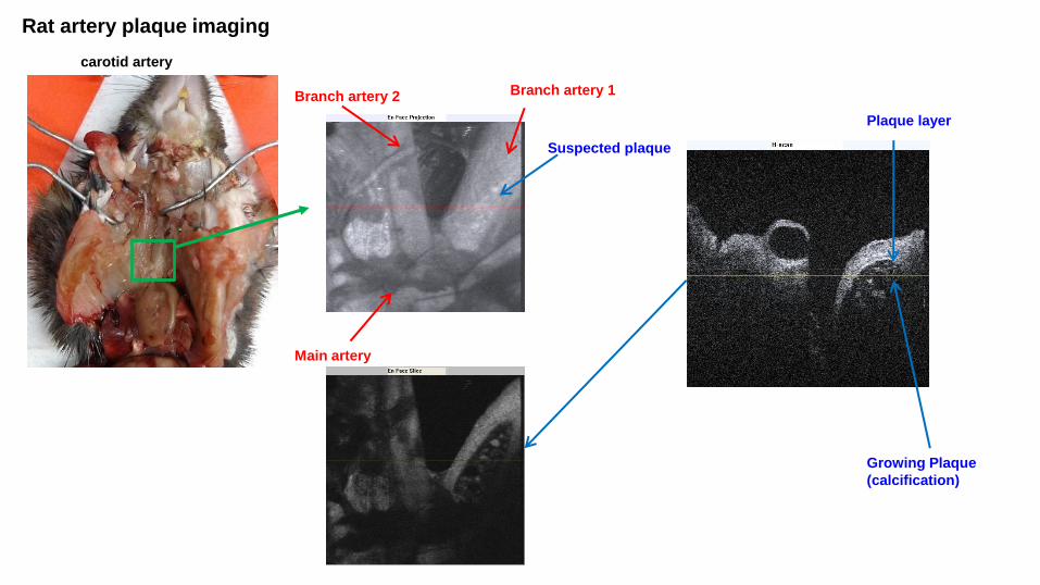
Rat artery plaque imaging
Main artery
Branch artery 1 Branch artery 2
Suspected plaque
carotid artery
Plaque layer
Growing Plaque
(calcification)
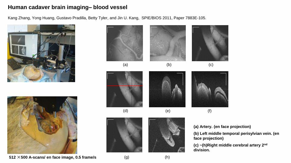
Human cadaver brain imaging– blood vessel
(d) (e) (f)
(a) (b) (c)
(a) Artery. (en face projection)
(b) Left middle temporal perisylvian vein. (en
face projection)
(c) ~(h)Right middle cerebral artery 2nd
division.
(g) (h) 512 ×500 A-scans/ en face image, 0.5 frame/s
Kang Zhang, Yong Huang, Gustavo Pradilla, Betty Tyler, and Jin U. Kang, SPIE/BIOS 2011, Paper 7883E-105.
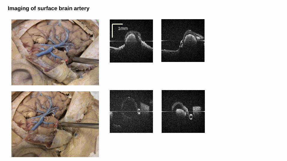
Imaging of surface brain artery
1mm
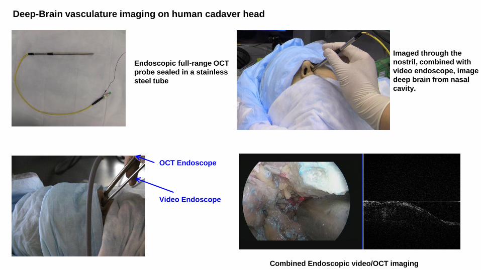
Imaged through the
nostril, combined with
video endoscope, image
deep brain from nasal
cavity.
Video Endoscope
OCT Endoscope
Combined Endoscopic video/OCT imaging
Endoscopic full-range OCT
probe sealed in a stainless
steel tube
Deep-Brain vasculature imaging on human cadaver head
We developed an ultrahigh speed, real-time OCT imaging platform
accelerated by GPU technology. The imaging platform is capable of
real-time data acquisition, reconstruction and visualization.
Several GPU-based algorithms were developed to accelerate the
signal processing and enhance image quality.
The performance of the GPU accelerated real-time OCT system was
validated by human cadaver and small animal model.
This technology could open the way for interventional OCT imaging
for applications in guided microsurgery.
Summary
NIH grants R21 1R21NS063131-01A1
Johns Hopkins Hospital: Dr. Peter Gehlbach, Dr. Gustavo Pradilla
Acknowledgements
Thank You!
Further Contact [email protected]
1 Research Circle Niskayuna, New York, 12309
Recommended