GLAST LAT Project ACD CDR January 7&8, 2003
Section 3 ACD Systems Engineering 1
GLAST Large Area Telescope:GLAST Large Area Telescope:
AntiCoincidence Detector (ACD)
CDR
January 2003
Michael Amato ACD Systems Engineering
M. Amato, G. Shiblie
Gamma-ray Large Gamma-ray Large Area Space Area Space TelescopeTelescope
GLAST LAT Project ACD CDR January 7&8, 2003
Section 3 ACD Systems Engineering 2
OutlineOutline
• System Overview• Requirements and Systems Documentation• Interfaces• Design Decisions/Major Trades• Verification• Risk• Technical Issues and Status
GLAST LAT Project ACD CDR January 7&8, 2003
Section 3 ACD Systems Engineering 3
System OverviewSystem Overview
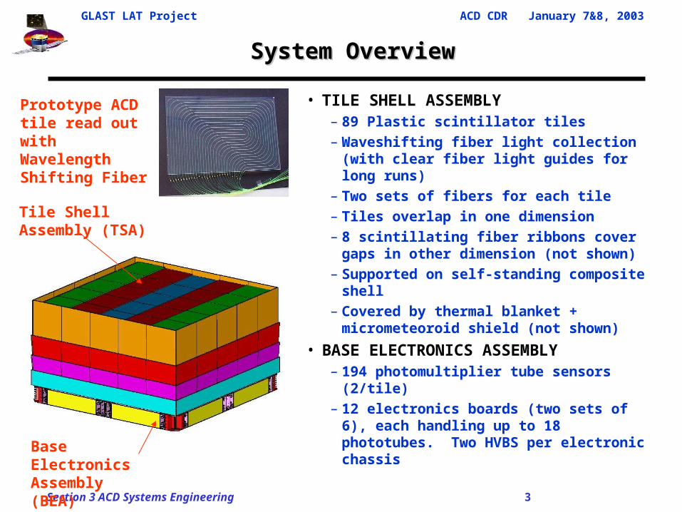
• TILE SHELL ASSEMBLY– 89 Plastic scintillator tiles– Waveshifting fiber light collection (with
clear fiber light guides for long runs)– Two sets of fibers for each tile– Tiles overlap in one dimension– 8 scintillating fiber ribbons cover gaps in
other dimension (not shown)– Supported on self-standing composite
shell– Covered by thermal blanket +
micrometeoroid shield (not shown)
• BASE ELECTRONICS ASSEMBLY– 194 photomultiplier tube sensors (2/tile)– 12 electronics boards (two sets of 6), each
handling up to 18 phototubes. Two HVBS per electronic chassis
Base Electronics Assembly (BEA)
Tile Shell Assembly (TSA)
Prototype ACD tile read out with Wavelength Shifting Fiber
GLAST LAT Project ACD CDR January 7&8, 2003
Section 3 ACD Systems Engineering 4
System OverviewSystem Overview
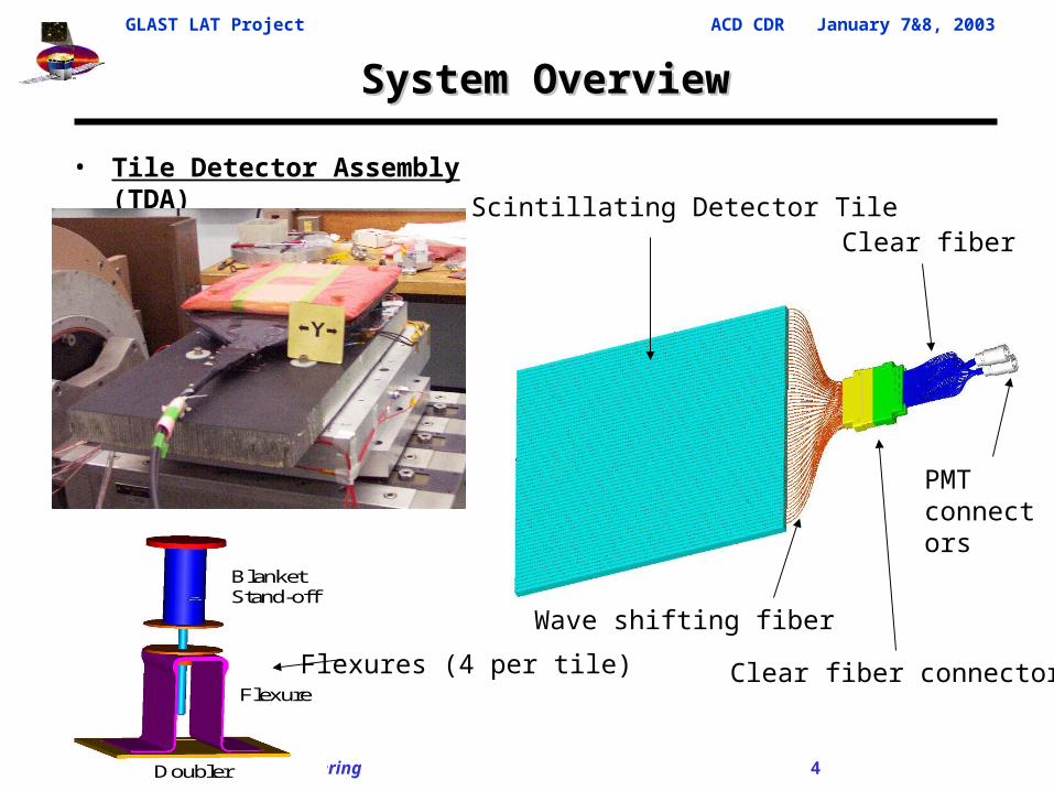
• Tile Detector Assembly (TDA)
Blanket Stand-off
Flexure
Doubler
Scintillating Detector Tile
Flexures (4 per tile)
Clear fiber
Clear fiber connector
Clear fiber connector
Wave shifting fiber
PMT connectors
GLAST LAT Project ACD CDR January 7&8, 2003
Section 3 ACD Systems Engineering 5
System OverviewSystem Overview
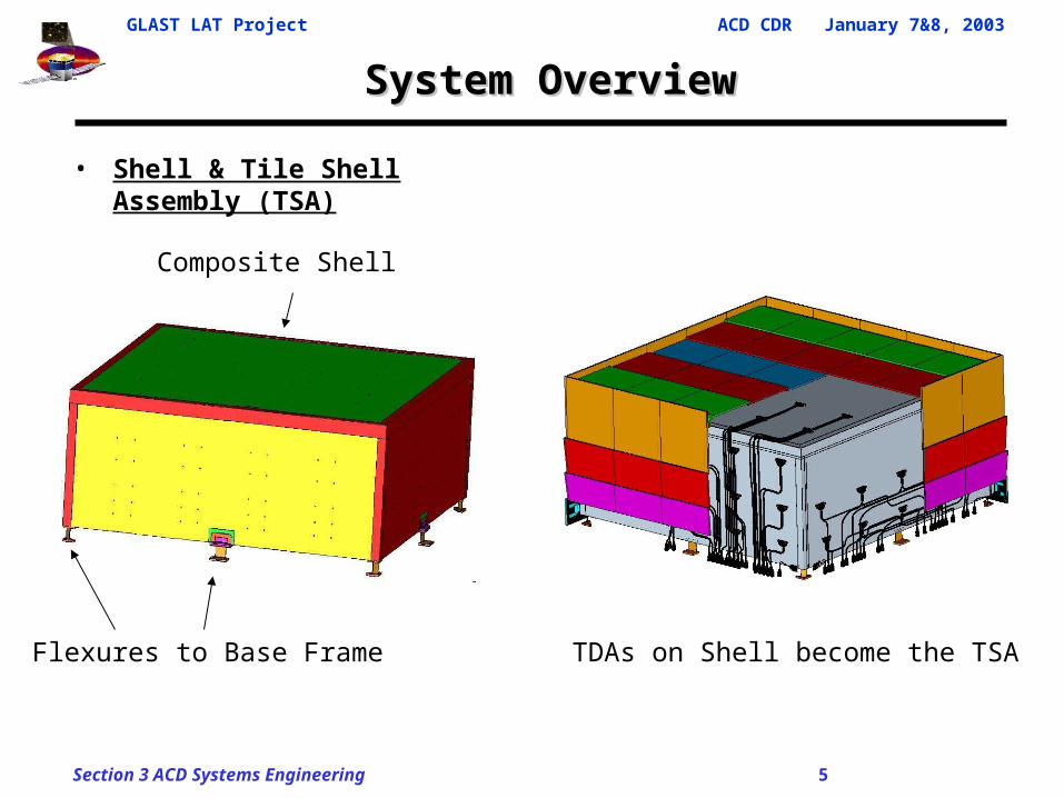
• Shell & Tile Shell Assembly (TSA)
Composite Shell
Flexures to Base Frame TDAs on Shell become the TSA
GLAST LAT Project ACD CDR January 7&8, 2003
Section 3 ACD Systems Engineering 6
System OverviewSystem Overview
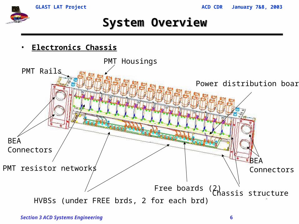
• Electronics Chassis
PMT Housings
PMT resistor networks
Free boards (2)
PMT Rails
HVBSs (under FREE brds, 2 for each brd)
Power distribution board
Chassis structure
BEA Connectors
BEA Connectors
GLAST LAT Project ACD CDR January 7&8, 2003
Section 3 ACD Systems Engineering 7
System OverviewSystem Overview
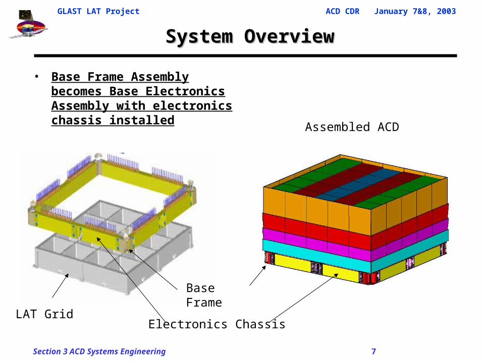
• Base Frame Assembly becomes Base Electronics Assembly with electronics chassis installed
Electronics Chassis
Assembled ACD
Base Frame
LAT Grid
GLAST LAT Project ACD CDR January 7&8, 2003
Section 3 ACD Systems Engineering 8
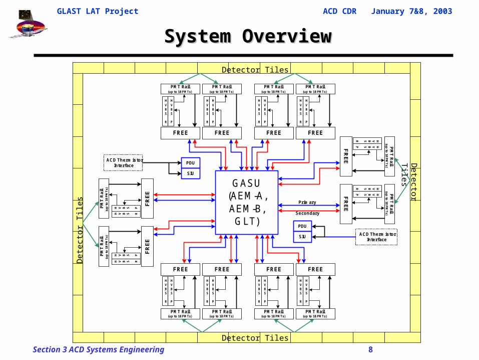
System OverviewSystem Overview
GASU(AEM-A,AEM-B,
GLT)
FREE
PMT Rail(up to 18 PMTs)
HVBS
R
HVBS
P
FREE
PMT Rail(up to 18 PMTs)
HVBS
R
HVBS
P
FREE
PMT Rail(up to 18 PMTs)
HVBS
R
HVBS
P
FREE
PMT Rail(up to 18 PMTs)
HVBS
R
HVBS
P
FREE
HVBS
R
PMT Rail(up to 18 PMTs)
HVBS
P
FREE
HVBS
R
PMT Rail(up to 18 PMTs)
HVBS
P
FREE
HVBS
R
PMT Rail(up to 18 PMTs)
HVBS
P
FREE
HVBS
R
PMT Rail(up to 18 PMTs)
HVBS
P
FR
EE
H V B S R
PM
T R
ail
(up
to
18
PM
Ts)
H V B S P
FR
EE
H V B S R
PM
T R
ail
(up
to
18
PM
Ts)
H V B S PF
RE
E
HVBSR
PM
T R
ail(u
p to
18 PM
Ts)
HVBSP
ACD Therm istorInterface
FR
EE
HVBSR
HVBSP PM
T R
ail(u
p to
18 PM
Ts)
ACD Therm istorInterface
PDU
SIU
PDU
SIU
Prim ary
Secondary
Detector TilesD
etec
tor
Til
es
Detector Tiles
Detector T
iles
GLAST LAT Project ACD CDR January 7&8, 2003
Section 3 ACD Systems Engineering 9
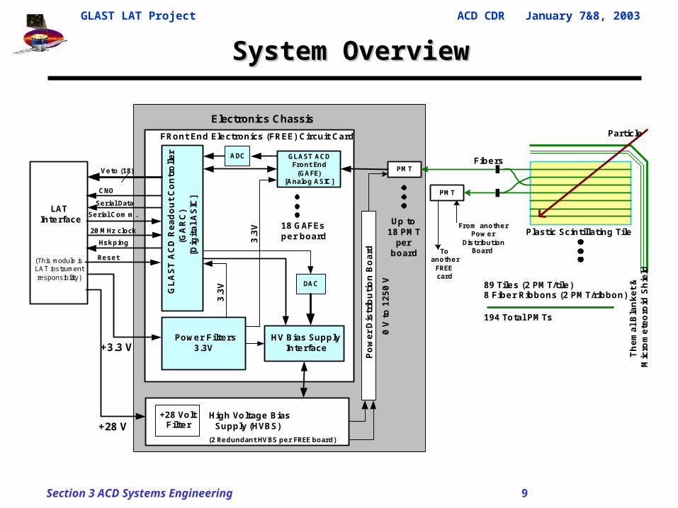
System OverviewSystem Overview
PMT
PMT
LATInterface
(This module isLAT instrumentresponsibility)
Fibers
Particle
Plastic Scintillating Tile
Th
em
al
Bla
nk
et
&M
icro
me
teo
roid
Sh
ield
89 Tiles (2 PM T/tile )8 Fiber Ribbons (2 PM T/ribbon)
194 Total PM Ts
From anotherPow er
DistributionBoard
GLAST ACDFront End
(GAFE)[Analog ASIC]
GL
AS
T A
CD
Re
ad
ou
t C
on
tro
lle
r(G
AR
C)
[Dig
ita
l A
SIC
]
Power Filte rs3.3V
HV Bias SupplyInterface
High Voltage BiasSupply (HVBS)
FRont End Electronics (FREE) Circuit Card
Veto (18)
Serial Data
Serial Com m .
0 V
to
12
50
V
3.3
V
3.3
V18 GAFEsper board
Hskping
(2 Redundant HVBS per FREE board)
ADC
DAC
Po
we
r D
istr
ibu
tio
n B
oa
rd Toanother
FREEcard
CNO
20 MHz clock
Reset
+28 VoltFilte r
+3.3 V
+28 V
Up to18 PM T
perboard
Electronics Chassis
GLAST LAT Project ACD CDR January 7&8, 2003
Section 3 ACD Systems Engineering 10
REQUIREMENTS
( & SYSTEMS DOCUMENTATION )
GLAST LAT Project ACD CDR January 7&8, 2003
Section 3 ACD Systems Engineering 11
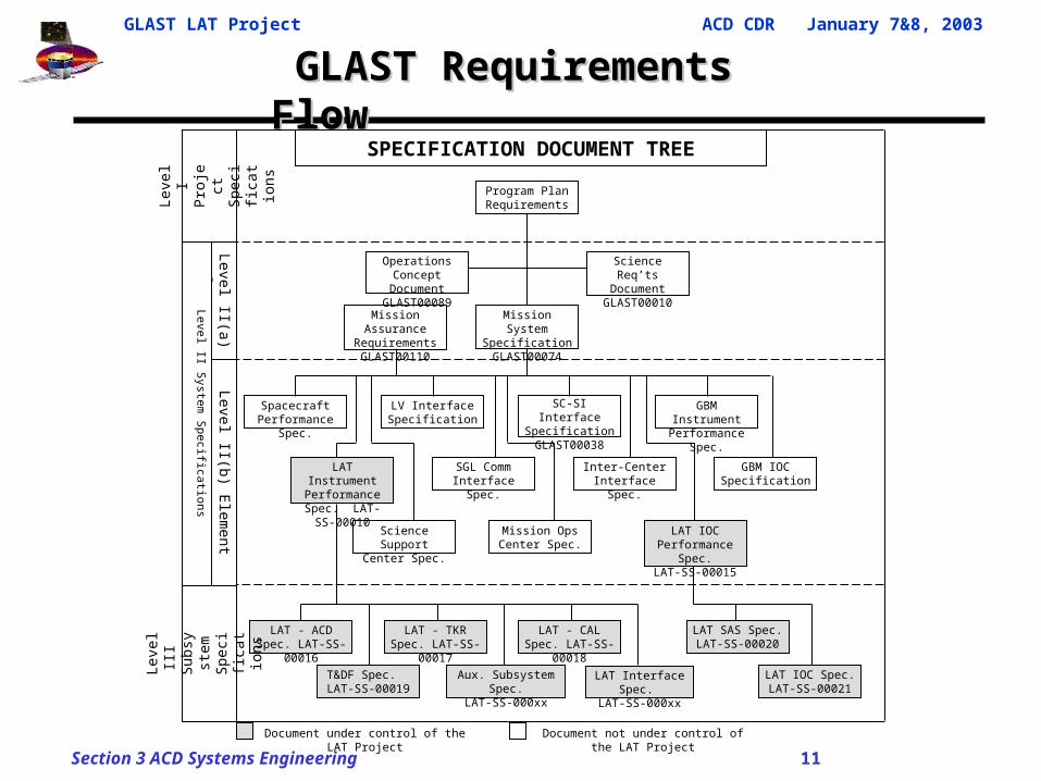
GLAST Requirements Flow GLAST Requirements Flow
Document under control of the LAT Project Document not under control of the LAT Project
Operations Concept Document
GLAST00089
LAT Instrument Performance Spec.
LAT-SS-00010
LAT - ACD Spec. LAT-SS-00016
LAT - TKR Spec. LAT-SS-00017
LAT - CAL Spec. LAT-SS-00018
T&DF Spec. LAT-SS-00019
Aux. Subsystem Spec.LAT-SS-000xx
Lev
el I
Proj
ect
Spec
ifi
catio
ns
Level II(a) System
Lev
el
III
Subs
yste
m
Spec
ifi
catio
ns
LAT IOC Spec. LAT-SS-00021
Program Plan Requirements
Science Req’ts Document
GLAST00010
Mission Assurance RequirementsGLAST00110
Mission System SpecificationGLAST00074
SGL Comm Interface Spec.
GBM Instrument Performance Spec.
LV Interface Specification
SC-SI Interface Specification GLAST00038
Spacecraft Performance Spec.
GBM IOC Specification
Inter-Center Interface Spec.
Mission Ops Center Spec.
Level II(b) E
lement
LAT Interface Spec. LAT-SS-000xx
LAT IOC Performance Spec.
LAT-SS-00015
SPECIFICATION DOCUMENT TREE
LAT SAS Spec. LAT-SS-00020
Science Support Center Spec.
Level II S
ystem S
pecifications
GLAST LAT Project ACD CDR January 7&8, 2003
Section 3 ACD Systems Engineering 12
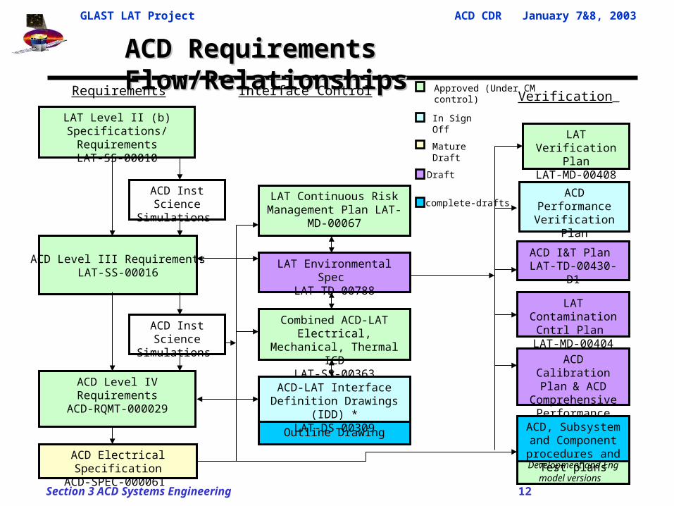
Outline Drawing
ACD Requirements Flow/Relationships ACD Requirements Flow/Relationships
ACD Electrical SpecificationACD-SPEC-000061
ACD Level III RequirementsLAT-SS-00016
LAT Verification PlanLAT-MD-00408
ACD PerformanceVerification Plan
ACD-PLAN-000050
ACD I&T Plan LAT-TD-00430-D1
Requirements Interface Control Verification
ACD Level IV RequirementsACD-RQMT-000029
LAT Level II (b)Specifications/Requirements
LAT-SS-00010
ACD Calibration Plan & ACD Comprehensive
Performance Test Plan
Approved (Under CM control)
Draft
In Sign Off
Mature Draft
Incomplete-drafts
LAT Contamination Cntrl Plan
LAT-MD-00404Combined ACD-LAT Electrical,
Mechanical, Thermal ICDLAT-SS-00363
ACD-LAT Interface Definition Drawings (IDD) *LAT-DS-00309
LAT Environmental Spec LAT-TD-00788
ACD Inst Science Simulations
ACD Inst Science Simulations
LAT Continuous Risk Management Plan LAT-MD-
00067
Development and Eng model versions
ACD, Subsystem and Component procedures
and Test plans
GLAST LAT Project ACD CDR January 7&8, 2003
Section 3 ACD Systems Engineering 13
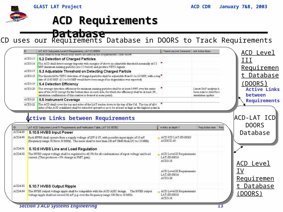
ACD Requirements Database ACD Requirements Database
ACD Level III Requirement Database (DOORS)
ACD Level IV Requirement Database (DOORS)
ACD-LAT ICD DOORS Database
ACD-LAT ICD DOORS Database
Active Links between Requirements
Active Links between Requirements
• ACD uses our Requirements Database in DOORS to Track Requirements
Screen capture of level IV doors tableScreen capture of level IV doors table
GLAST LAT Project ACD CDR January 7&8, 2003
Section 3 ACD Systems Engineering 14
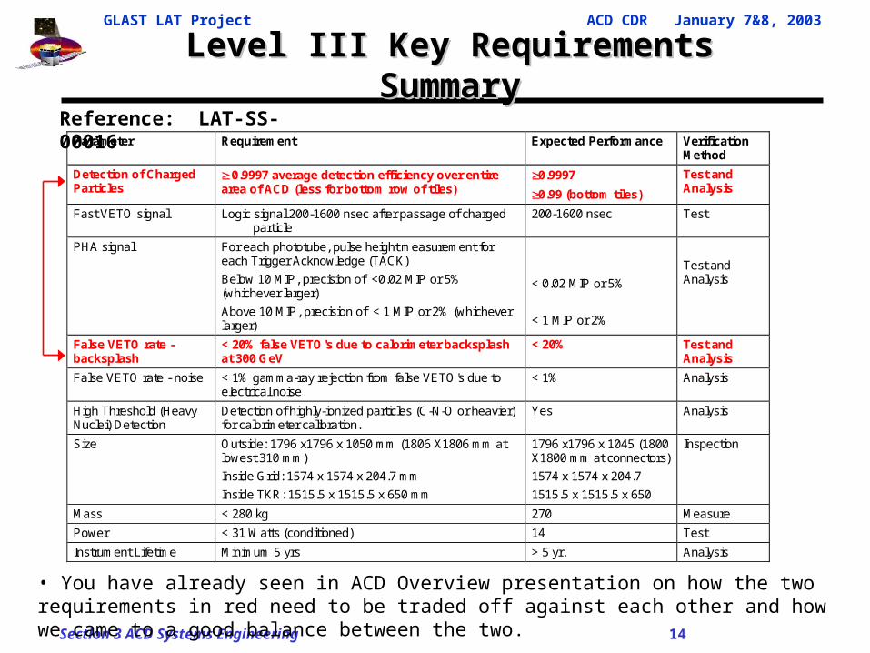
Level III Key Requirements SummaryLevel III Key Requirements Summary
Parameter Requirement Expected Performance Verification Method
Detection of Charged Particles
0.9997 average detection efficiency over entire area of ACD (less for bottom row of tiles)
0.9997
0.99 (bottom tiles)
Test and Analysis
Fast VETO signal Logic signal 200-1600 nsec after passage of charged particle
200-1600 nsec Test
PHA signal For each phototube, pulse height measurement for each Trigger Acknowledge (TACK)
Below 10 MIP, precision of <0.02 MIP or 5% (whichever larger)
Above 10 MIP, precision of < 1 MIP or 2% (whichever larger)
< 0.02 MIP or 5%
< 1 MIP or 2%
Test and Analysis
False VETO rate - backsplash
< 20% false VETO's due to calorimeter backsplash at 300 GeV
< 20% Test and Analysis
False VETO rate - noise < 1% gamma-ray rejection from false VETO's due to electrical noise
< 1% Analysis
High Threshold (Heavy Nuclei) Detection
Detection of highly-ionized particles (C-N-O or heavier) for calorimeter calibration.
Yes Analysis
Size Outside: 1796 x1796 x 1050 mm (1806 X1806 mm at lowest 310 mm)
Inside Grid: 1574 x 1574 x 204.7 mm
Inside TKR: 1515.5 x 1515.5 x 650 mm
1796 x1796 x 1045 (1800 X1800 mm at connectors)
1574 x 1574 x 204.7
1515.5 x 1515.5 x 650
Inspection
Mass < 280 kg 270 Measure
Power < 31 Watts (conditioned) 14 Test
Instrument Lifetime Minimum 5 yrs > 5 yr. Analysis
Reference: LAT-SS-00016
• You have already seen in ACD Overview presentation on how the two requirements in red need to be traded off against each other and how we came to a good balance between the two.
GLAST LAT Project ACD CDR January 7&8, 2003
Section 3 ACD Systems Engineering 15
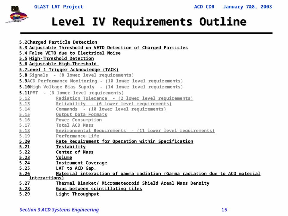
Level IV Requirements OutlineLevel IV Requirements Outline
5.2Charged Particle Detection5.3 Adjustable Threshold on VETO Detection of Charged Particles5.4 False VETO due to Electrical Noise5.5 High-Threshold Detection5.6 Adjustable High-Threshold 5.7Level 1 Trigger Acknowledge (TACK)5.8 Signals - (8 lower level requirements)5.9ACD Performance Monitoring - (10 lower level requirements)5.10High Voltage Bias Supply - (14 lower level requirements)5.11PMT - (6 lower level requirements)5.12 Radiation Tolerance - (2 lower level requirements)5.13 Reliability - (6 lower level requirements)5.14 Commands - (10 lower level requirements)5.15 Output Data Formats5.16 Power Consumption5.17 Total ACD Mass5.18 Environmental Requirements - (11 lower level requirements)5.19 Performance Life5.20 Rate Requirement for Operation within Specification5.21 Testability5.22 Center of Mass5.23 Volume5.24 Instrument Coverage5.25 LAT to ACD Gap.5.26 Material interaction of gamma radiation (Gamma radiation due to ACD material interactions)5.27 Thermal Blanket/ Micrometeoroid Shield Areal Mass Density5.28 Gaps between scintillating tiles5.29 Light Throughput
GLAST LAT Project ACD CDR January 7&8, 2003
Section 3 ACD Systems Engineering 16
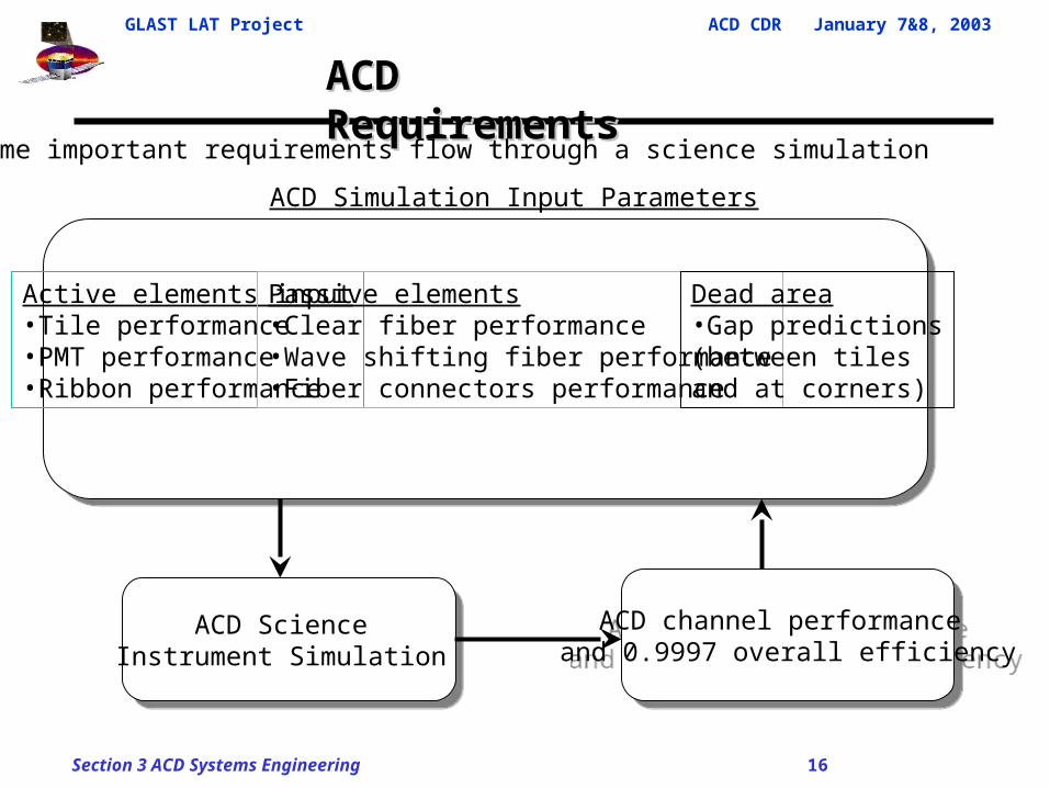
ACD Requirements ACD Requirements
ACD Simulation Input Parameters
ACD Science Instrument Simulation
ACD Science Instrument Simulation
ACD channel performance and 0.9997 overall efficiency
ACD channel performance and 0.9997 overall efficiency
• Some important requirements flow through a science simulation
Active elements input•Tile performance•PMT performance•Ribbon performance
Passive elements•Clear fiber performance•Wave shifting fiber performance•Fiber connectors performance
Dead area•Gap predictions(between tiles and at corners)
GLAST LAT Project ACD CDR January 7&8, 2003
Section 3 ACD Systems Engineering 17
INTERFACES
GLAST LAT Project ACD CDR January 7&8, 2003
Section 3 ACD Systems Engineering 18
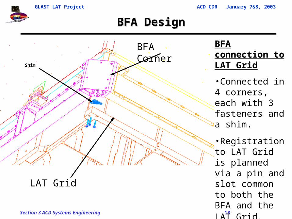
BFA DesignBFA Design
BFA connection to LAT Grid
•Connected in 4 corners, each with 3 fasteners and a shim.
•Registration to LAT Grid is planned via a pin and slot common to both the BFA and the LAT Grid.
BFA Corner
LAT Grid
Shim
GLAST LAT Project ACD CDR January 7&8, 2003
Section 3 ACD Systems Engineering 19
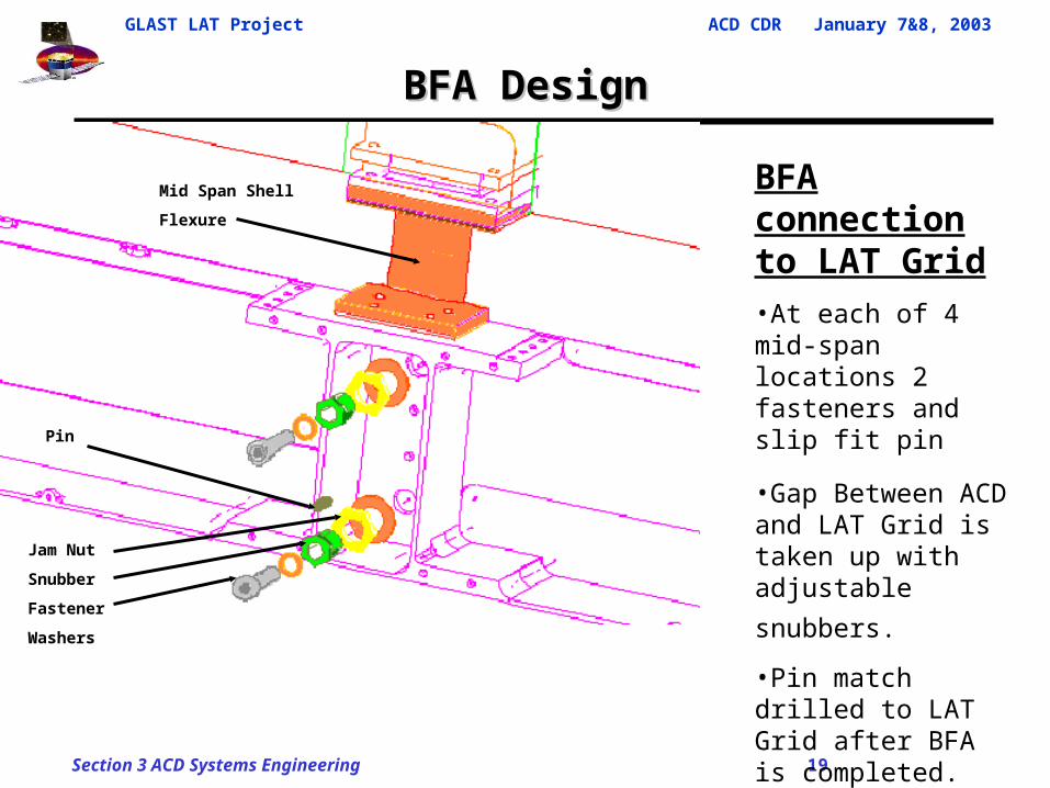
BFA DesignBFA Design
BFA connection to LAT Grid •At each of 4 mid-span locations 2 fasteners and slip fit pin
•Gap Between ACD and LAT Grid is taken up with adjustable
snubbers. •Pin match drilled to LAT Grid after BFA is completed.
•Pin is captured to accommodate slip fit.
Jam Nut
Snubber
Fastener
Washers
Pin
Mid Span Shell
Flexure
GLAST LAT Project ACD CDR January 7&8, 2003
Section 3 ACD Systems Engineering 20
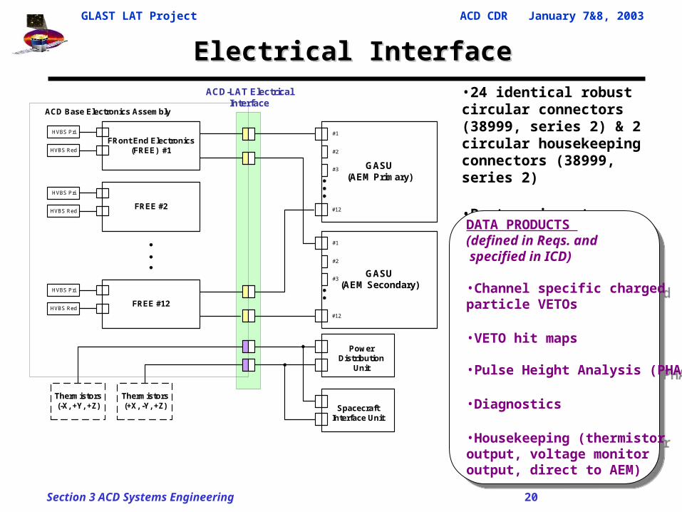
Electrical InterfaceElectrical Interface•24 identical robust circular connectors (38999, series 2) & 2 circular housekeeping connectors (38999, series 2)
•Parts, pin outs, signal def, grounding all defined in ICD
DATA PRODUCTS (defined in Reqs. and specified in ICD)
•Channel specific charged particle VETOs
•VETO hit maps
•Pulse Height Analysis (PHA)
•Diagnostics
•Housekeeping (thermistor output, voltage monitor output, direct to AEM)
DATA PRODUCTS (defined in Reqs. and specified in ICD)
•Channel specific charged particle VETOs
•VETO hit maps
•Pulse Height Analysis (PHA)
•Diagnostics
•Housekeeping (thermistor output, voltage monitor output, direct to AEM)
FRont End Electronics(FREE) #1
HVBS Pri
HVBS Red
FREE #2
HVBS Pri
HVBS Red
FREE #12
HVBS Pri
HVBS Red
GASU(AEM Primary)
#1
#2
#3
#12
GASU(AEM Secondary)
#1
#2
#3
#12
Thermistors(-X, +Y, +Z)
Thermistors(+X, -Y, +Z)
ACD Base Electronics Assembly
PowerDistribution
Unit
SpacecraftInterface Unit
ACD-LAT ElectricalInterface
GLAST LAT Project ACD CDR January 7&8, 2003
Section 3 ACD Systems Engineering 21
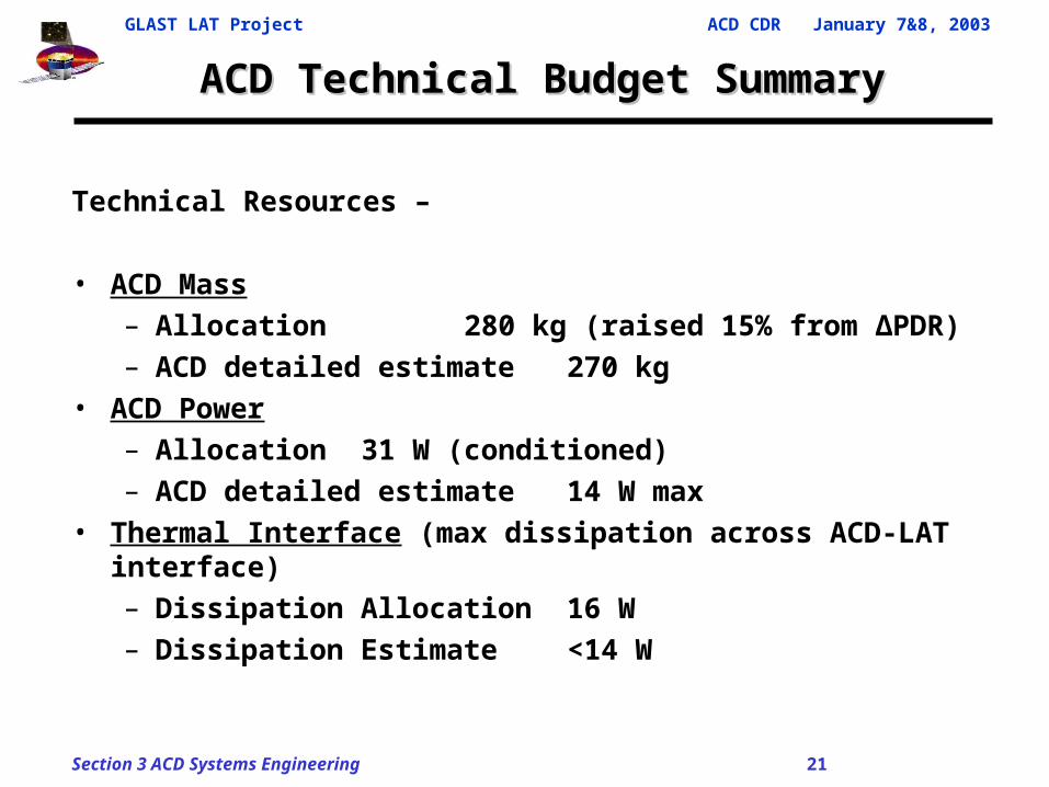
ACD Technical Budget SummaryACD Technical Budget Summary
Technical Resources –
• ACD Mass
– Allocation 280 kg (raised 15% from ΔPDR)– ACD detailed estimate 270 kg
• ACD Power– Allocation 31 W (conditioned)– ACD detailed estimate 14 W max
• Thermal Interface (max dissipation across ACD-LAT interface)– Dissipation Allocation 16 W– Dissipation Estimate <14 W
GLAST LAT Project ACD CDR January 7&8, 2003
Section 3 ACD Systems Engineering 22
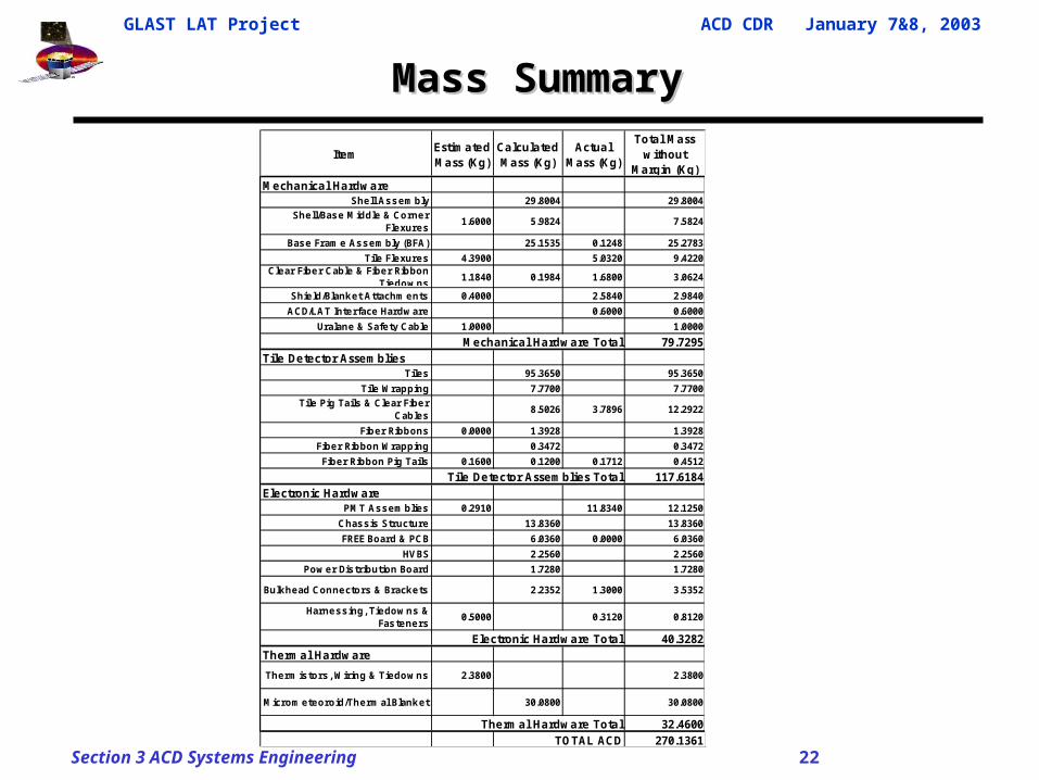
Mass SummaryMass Summary
ItemEstimated Mass (Kg)
Calculated Mass (Kg)
Actual Mass (Kg)
Total Mass without
Margin (Kg)Mechanical Hardware
Shell Assem bly 29.8004 29.8004
Shell/Base M iddle & Corner Flexures
1.6000 5.9824 7.5824
Base Fram e Assem bly (BFA) 25.1535 0.1248 25.2783
Tile Flexures 4.3900 5.0320 9.4220Clear Fiber Cable & Fiber Ribbon
Tiedow ns1.1840 0.1984 1.6800 3.0624
Shie ld/Blanket Attachm ents 0.4000 2.5840 2.9840
ACD/LAT Interface Hardw are 0.6000 0.6000
Uralane & Safe ty Cable 1.0000 1.0000
Mechanical Hardware Total 79.7295Tile Detector Assemblies
Tiles 95.3650 95.3650
Tile Wrapping 7.7700 7.7700
Tile Pig Tails & Clear Fiber Cables
8.5026 3.7896 12.2922
Fiber Ribbons 0.0000 1.3928 1.3928
Fiber Ribbon Wrapping 0.3472 0.3472
Fiber Ribbon Pig Tails 0.1600 0.1200 0.1712 0.4512
Tile Detector Assemblies Total 117.6184Electronic Hardware
PM T Assem blies 0.2910 11.8340 12.1250
Chassis Structure 13.8360 13.8360
FREE Board & PCB 6.0360 0.0000 6.0360
HVBS 2.2560 2.2560
Pow er Dis tribution Board 1.7280 1.7280
Bulkhead Connectors & Brackets 2.2352 1.3000 3.5352
Harness ing, Tiedow ns & Fasteners
0.5000 0.3120 0.8120
Electronic Hardware Total 40.3282Thermal Hardware
Therm istors , Wiring & Tiedow ns 2.3800 2.3800
M icrom eteoroid/Therm al Blanket 30.0800 30.0800
Thermal Hardware Total 32.4600TOTAL ACD 270.1361
GLAST LAT Project ACD CDR January 7&8, 2003
Section 3 ACD Systems Engineering 23
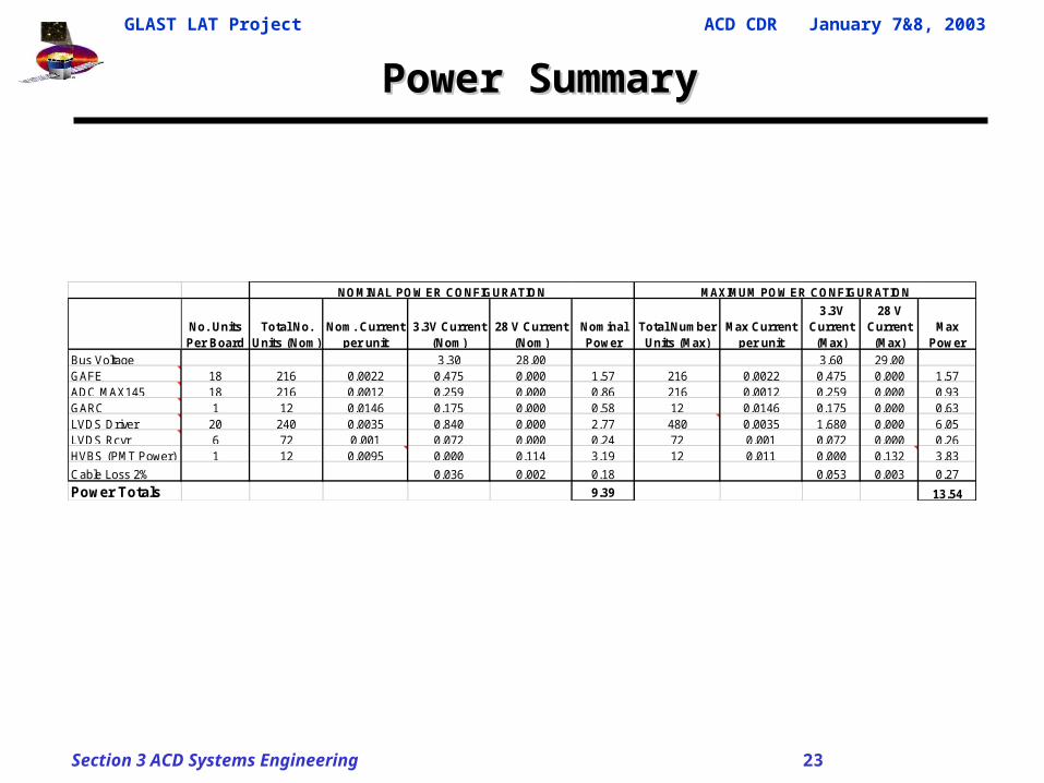
Power SummaryPower Summary
No. Units Per Board
Total No. Units (Nom)
Nom. Current per unit
3.3V Current (Nom)
28 V Current (Nom)
Nominal Power
Total Number Units (Max)
Max Current per unit
3.3V Current (Max)
28 V Current (Max)
Max Power
Bus Voltage 3.30 28.00 3.60 29.00GAFE 18 216 0.0022 0.475 0.000 1.57 216 0.0022 0.475 0.000 1.57ADC MAX145 18 216 0.0012 0.259 0.000 0.86 216 0.0012 0.259 0.000 0.93GARC 1 12 0.0146 0.175 0.000 0.58 12 0.0146 0.175 0.000 0.63LVDS Driver 20 240 0.0035 0.840 0.000 2.77 480 0.0035 1.680 0.000 6.05LVDS Rcvr 6 72 0.001 0.072 0.000 0.24 72 0.001 0.072 0.000 0.26HVBS (PMT Power) 1 12 0.0095 0.000 0.114 3.19 12 0.011 0.000 0.132 3.83
Cable Loss 2% 0.036 0.002 0.18 0.053 0.003 0.27
Power Totals 9.39 13.54
NOMINAL POWER CONFIGURATION MAXIMUM POWER CONFIGURATION
GLAST LAT Project ACD CDR January 7&8, 2003
Section 3 ACD Systems Engineering 24
DESIGN DECISIONS
GLAST LAT Project ACD CDR January 7&8, 2003
Section 3 ACD Systems Engineering 25
Design Decisions - R&D Testing Design Decisions - R&D Testing
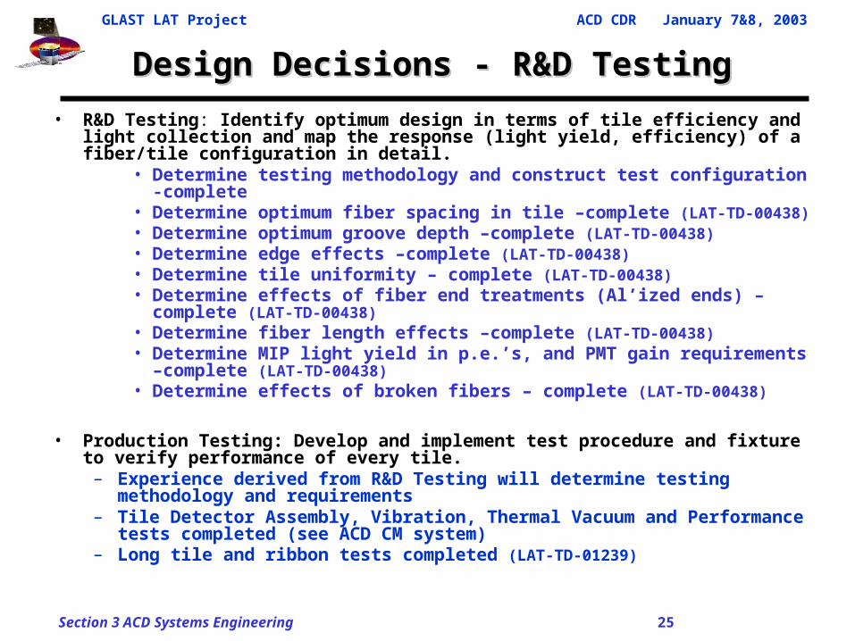
• R&D Testing: Identify optimum design in terms of tile efficiency and light collection and map the response (light yield, efficiency) of a fiber/tile configuration in detail.
• Determine testing methodology and construct test configuration -complete• Determine optimum fiber spacing in tile –complete (LAT-TD-00438)• Determine optimum groove depth –complete (LAT-TD-00438)• Determine edge effects –complete (LAT-TD-00438)• Determine tile uniformity – complete (LAT-TD-00438)• Determine effects of fiber end treatments (Al’ized ends) – complete (LAT-TD-
00438)• Determine fiber length effects –complete (LAT-TD-00438)• Determine MIP light yield in p.e.’s, and PMT gain requirements –complete
(LAT-TD-00438)• Determine effects of broken fibers – complete (LAT-TD-00438)
• Production Testing: Develop and implement test procedure and fixture to verify performance of every tile.
– Experience derived from R&D Testing will determine testing methodology and requirements
– Tile Detector Assembly, Vibration, Thermal Vacuum and Performance tests completed (see ACD CM system)
– Long tile and ribbon tests completed (LAT-TD-01239)
GLAST LAT Project ACD CDR January 7&8, 2003
Section 3 ACD Systems Engineering 26
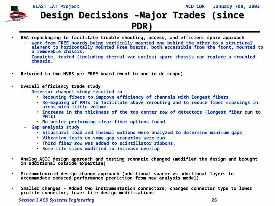
Design Decisions –Major Trades (since PDR)Design Decisions –Major Trades (since PDR)
• BEA repackaging to facilitate trouble shooting, access, and efficient spare approach – Went from FREE boards being vertically mounted one behind the other to a structural element to
horizontally mounted Free boards, both accessible from the front, mounted to a removable chassis.
– Complete, tested (including thermal vac cycles) spare chassis can replace a troubled chassis.
• Returned to two HVBS per FREE board (went to one in de-scope)
• Overall efficiency trade study– Detector channel study resulted in
• Rerouting fibers to improve efficiency of channels with longest fibers• Re-mapping of PMTs to facilitate above rerouting and to reduce fiber crossings in areas with
little volume.• Increase in the thickness of the top center row of detectors (longest fiber run to PMTs)• No better performing clear fiber options found
– Gap analysis study• Structural load and thermal motions were analyzed to determine minimum gaps• Vibration tests on some gap scenarios were run• Third fiber row was added to scintillator ribbons.• Some tile sizes modified to increase overlap
• Analog ASIC design approach and testing scenario changed (modified the design and brought in additional outside expertise)
• Micrometeoroid design change approach (additional spacer vs additional layers to accommodate reduced performance prediction from new analysis model)
• Smaller changes – Added two instrumentation connectors, changed connector type to lower profile connector, lower tile design modifications
GLAST LAT Project ACD CDR January 7&8, 2003
Section 3 ACD Systems Engineering 27
VERIFICATION
GLAST LAT Project ACD CDR January 7&8, 2003
Section 3 ACD Systems Engineering 28
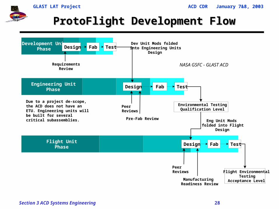
ProtoFlight Development FlowProtoFlight Development Flow
Due to a project de-scope, the ACD does not have an ETU. Engineering units will be built for several critical subassemblies.
Development UnitPhase Design Fab Test
Engineering UnitPhase
Design Fab Test
Flight UnitPhase
Design Fab Test
Flight Environmental Testing
Acceptance Level
Environmental TestingQualification Level
PeerReviews
PeerReviews
Dev Unit Mods foldedinto Engineering Units
Design
RequirementsReview
Eng Unit Modsfolded into Flight
Design
Pre-Fab Review
ManufacturingReadiness Review
NASA GSFC - GLAST ACD
GLAST LAT Project ACD CDR January 7&8, 2003
Section 3 ACD Systems Engineering 29
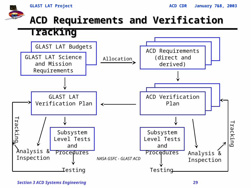
ACD Requirements and Verification TrackingACD Requirements and Verification Tracking
GLAST LAT Budgets
GLAST LAT Science and Mission Requirements
ACD Requirements(direct and derived)
Subsystem Level Tests and
Procedures
GLAST LAT Verification Plan ACD Verification Plan
Subsystem Level Tests and
Procedures
Testing
Analysis & Inspection
Tracking
Testing
Analysis & Inspection
Tracking
Allocation
NASA GSFC - GLAST ACD
GLAST LAT Project ACD CDR January 7&8, 2003
Section 3 ACD Systems Engineering 30
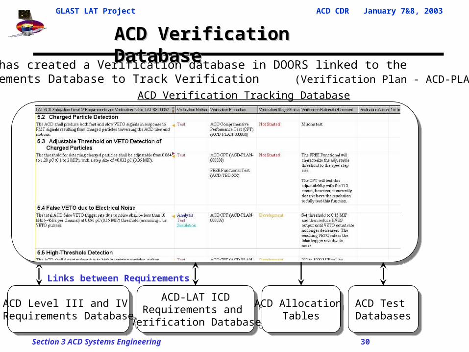
ACD Verification Database ACD Verification Database
ACD Verification Tracking Database
ACD-LAT ICDRequirements and
Verification Database
ACD-LAT ICDRequirements and
Verification Database
Links between Requirements
• ACD has created a Verification database in DOORS linked to the Requirements Database to Track Verification (Verification Plan - ACD-PLAN-000050)
ACD Level III and IV Requirements Database
ACD Level III and IV Requirements Database
ACD Test Databases
ACD Test Databases
ACD Allocation Tables
ACD Allocation Tables
GLAST LAT Project ACD CDR January 7&8, 2003
Section 3 ACD Systems Engineering 31
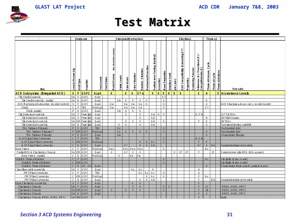
Test MatrixTest Matrix
Lev
el o
f A
ssem
bly
Un
it T
ype
Su
pp
lier
Tes
t L
evel
s
Tes
t S
tatu
s
Mo
dal
Su
rvey
(l
ow
leve
l sin
e su
rvey
)
Sta
tic
Lo
ads
Sin
e B
urs
t
Sin
e V
ibra
tio
n
Ran
do
m V
ibra
tio
n
Mec
han
ical
Fu
nct
ion
Per
form
ance
Tes
tin
g (
Op
tica
l)
Aco
ust
ics
Mas
s P
rop
erti
es
Inte
rfac
e V
erif
.
EM
C/E
MI
ES
D C
om
pat
ibil
ity
(Gro
un
din
g)?
??
Mag
net
ics
Scr
een
ing
Pro
cess
Ali
ven
ess
(A)
/ F
un
ctio
nal
(F
) /
Co
mp
reh
ensi
ve (
C)
Th
erm
al-V
acu
um
Cyc
le
Th
erm
al C
ycle
Th
erm
al B
alan
ce
Remarks
ACD Subsystem (Integrated ACD) S F GSFC Acpt X X X X?-r X X X X X X C 4 X Acceptance LevelsSA F GSFC Acpt X ?SA D GSFC Qual X-b X X X X X 6S F GSFC Qual X-e X-e X-e X-e X X 2 ACD Structure w/mass sims, no elect or detC F TBD Par Qual X-e X-e X-e X-e X 2 ?P D GSFC Qual X-b h h h
SA F Fermilab Acpt X X X-d h X A, F-h 117 Flt TDAs SA S Fermilab Acpt X X-d 8 28 Flight SparesSA EM Fermilab Qual X X X X-d X F 6 20 TDAs
Tile Detector Assembly SA D Fermilab Qual X X X X-d 6 Functional testing code660 TDA Tiedown (Flexure) P F GSFC TBD X-c X Test bonded joint TDA Tiedown (Flexure) ? P EM GSFC Par Qual X-c X X X X X h Test bonded joint TDA Tiedown (Flexure) P D GSFC Qual X-b h Characterize flexures
C F GSFC TBD X A, F-hC EM GSFC Par Qual h X X-c X F h
WSF/Clear Fiber Connector C D GSFC Qual X ? h X X-d A? h 8-d Several development modelsC F GSFC Par Qual X-e-c X-e-c X-e-c X-e-c X 4-c
SA EM GSFC Qual X X-? X X X X? X? F 2? Corner or one side BFA, BEA assembC D GSFC Par Qual X X-e X-e
Shield & Thermal Blanket C F GSFC X 4-c Similarity to dev. model Shield & Thermal Blanket C EM GSFC X Similarity to dev. model
C D JSC, GSFCQual 6 Characterize thermal perf., particle impactClear fiber cable assembly SA F GSFC Qual X-c X-c X A
C F GSFC TBD X-c X-c X-c X AC EM GSFC Par Qual X X-c X F 6-c
PMT/Fiber Connector C D GSFC Qual X X X-d F 8-d Several development modelsS F GSFC Acpt X X F
SA F GSFC Acpt X X X X F 2? (FREE, HVBS, PMT)SA EM GSFC Qual X X X X X F 10 (FREE, HVBS, PMT)SA D GSFC Qual F 2 (FREE, HVBS, PMT)
Electronics Chassis (FREE, HVBS, PMT) SA BB GSFC F (FREE, HVBS, PMT) bred brd does not req mech BEA parts
Shell Shell - partial Tile Detector Assembly Tile Detector Assembly
Electronics Chassis Electronics Chassis
Tile Detector Assembly
WSF/Clear Fiber Connector WSF/Clear Fiber Connector
Base Frame Partial BFA & Electronics Chassis
Base Electronics Assembly Electronics Chassis
Base Frame - partial
Shield & Thermal Blanket
PMT/Fiber Connector PMT/Fiber Connector
Thermal
Item
Tile Shell Assembly Tile Shell Assembly - partial ACD Mechanical Subsystem (no elect or Det)
Structural/MechanicalHardware Electrical
GLAST LAT Project ACD CDR January 7&8, 2003
Section 3 ACD Systems Engineering 32
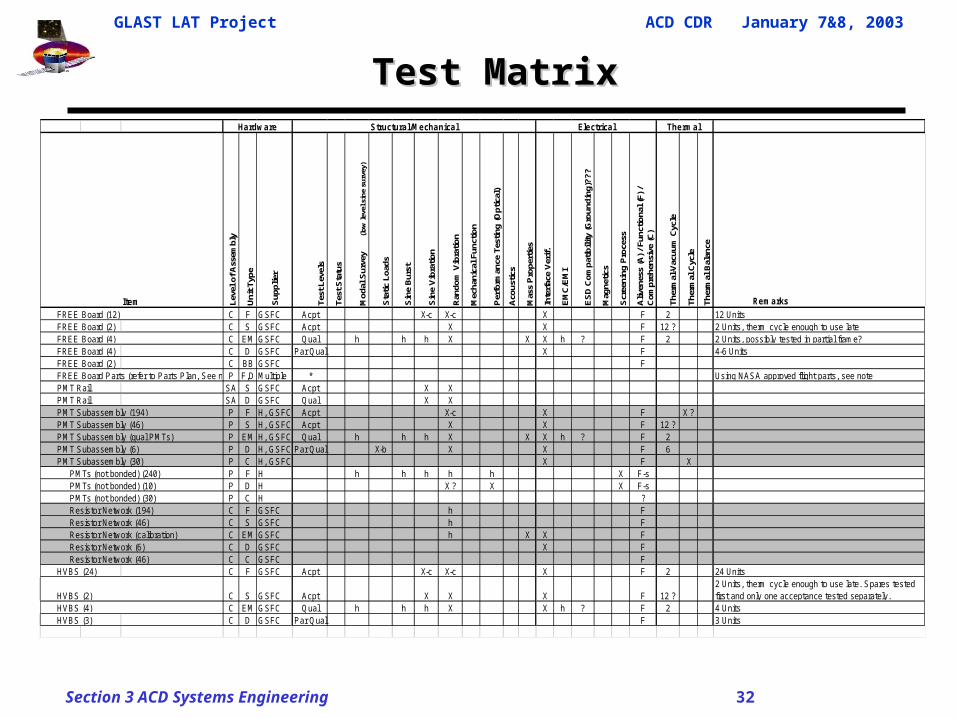
Test MatrixTest Matrix
Leve
l of A
ssem
bly
Uni
t Typ
e
Sup
plie
r
Test
Lev
els
Test
Sta
tus
Mod
al S
urve
y (lo
w le
vel s
ine
surv
ey)
Sta
tic L
oads
Sin
e B
urst
Sin
e V
ibra
tion
Ran
dom
Vib
ratio
n
Mec
hani
cal F
unct
ion
Per
form
ance
Tes
ting
(Opt
ical
)
Aco
ustic
s
Mas
s P
rope
rtie
s
Inte
rfac
e V
erif.
EM
C/E
MI
ES
D C
ompa
tibili
ty (G
roun
ding
)???
Mag
netic
s
Scr
eeni
ng P
roce
ss
Aliv
enes
s (A
) / F
unct
iona
l (F)
/ C
ompr
ehen
sive
(C)
Ther
mal
-Vac
uum
Cyc
le
Ther
mal
Cyc
le
Ther
mal
Bal
ance
Remarks
C F GSFC Acpt X-c X-c X F 2 12 Units FREE Board (2) C S GSFC Acpt X X F 12 ? 2 Units, therm cycle enough to use late
C EM GSFC Qual h h h X X X h ? F 2 2 Units, possibly tested in partial frame? FREE Board (4) C D GSFC Par Qual X F 4-6 Units FREE Board (2) C BB GSFC F FREE Board Parts (refer to Parts Plan, See note)P F,D Multiple * Using NASA approved flight parts, see note PMT Rail SA S GSFC Acpt X X PMT Rail SA D GSFC Qual X X
P F H, GSFC Acpt X-c X F X ? PMT Subassembly (46) P S H, GSFC Acpt X X F 12 ? PMT Subassembly (qual PMTs) P EM H, GSFC Qual h h h X X X h ? F 2 PMT Subassembly (6) P D H, GSFC Par Qual X-b X X F 6 PMT Subassembly (30) P C H, GSFC X F X PMTs (not bonded) (240) P F H h h h h h X F-s PMTs (not bonded) (10) P D H X ? X X F-s PMTs (not bonded) (30) P C H ? Resistor Network (194) C F GSFC h F Resistor Network (46) C S GSFC h F Resistor Network (calibration) C EM GSFC h X X F Resistor Network (6) C D GSFC X F Resistor Network (46) C C GSFC F HVBS (24) C F GSFC Acpt X-c X-c X F 2 24 Units
C S GSFC Acpt X X X F 12 ?2 Units, therm cycle enough to use late. Spares tested first and only one acceptance tested separately.
C EM GSFC Qual h h h X X h ? F 2 4 Units HVBS (3) C D GSFC Par Qual F 3 Units
FREE Board (4)
PMT Subassembly (194)
HVBS (2) HVBS (4)
Thermal
Item FREE Board (12)
Structural/MechanicalHardware Electrical
GLAST LAT Project ACD CDR January 7&8, 2003
Section 3 ACD Systems Engineering 33
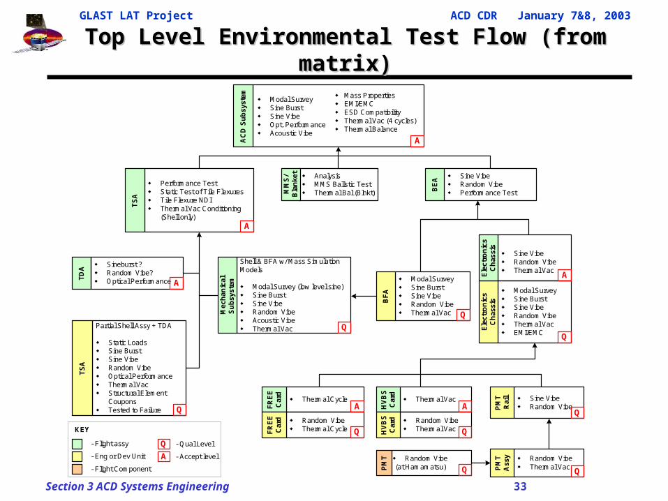
Top Level Environmental Test Flow (from matrix)Top Level Environmental Test Flow (from matrix)
Partial Shell Assy + TDA
Static Loads Sine Burst Sine Vibe Random Vibe Optical Performance Thermal Vac Structural Element
Coupons Tested to Failure
TS
A
Q
Shell & BFA w/ Mass SimulationModels
Modal Survey (low level sine) Sine Burst Sine Vibe Random Vibe Acoustic Vibe Thermal Vac
Mec
han
ical
Su
bsy
stem
Q
Modal Survey Sine Burst Sine Vibe Random Vibe Thermal Vac EMI/EMC
Ele
ctro
nic
sC
has
sis
Q
Sine Vibe Random Vibe Thermal Vac
Ele
ctro
nic
sC
has
sis
A
Thermal Cycle
FR
EE
Car
d
Random Vibe Thermal CycleF
RE
EC
ard
Q
A Thermal Vac
HV
BS
Car
d
Random Vibe Thermal VacH
VB
SC
ard
Q
A
Sine Vibe Random Vibe Performance TestB
EA
Sine Vibe Random VibeP
MT
Rai
l
Q
Random Vibe Thermal VacP
MT
Ass
y
Q
Random Vibe(at Hamamatsu)P
MT
Q
Performance Test Static Test of Tile Flexures Tile Flexure NDI Thermal Vac Conditioning
(Shell only)
TS
A
A
- Flight assy
- Eng or Dev Unit
- Flight Component
- Qual Level
- Accept levelA
Q
KEY
Modal Survey Sine Burst Sine Vibe Random Vibe Thermal Vac
BF
A
Q
AC
D S
ub
syst
em
A
Modal Survey Sine Burst Sine Vibe Opt. Performance Acoustic Vibe
Mass Properties EMI/EMC ESD Compatibility Thermal Vac (4 cycles) Thermal Balance
TD
A
Sineburst ? Random Vibe? Optical Performance A
Analysis MMS Ballstic Test Thermal Bal (Blnkt)M
MS
/B
lan
ket
GLAST LAT Project ACD CDR January 7&8, 2003
Section 3 ACD Systems Engineering 34
RISK (Briefly)
GLAST LAT Project ACD CDR January 7&8, 2003
Section 3 ACD Systems Engineering 35
RiskRisk
• If failures occur, ACD is designed to fail ‘gracefully’, major failures result in incremental steps in performance. Other than a major micrometeoroid hit, it takes multiple failures to fail a detector channel. Complete detector channel failures leave holes in coverage.
• Micrometeoroid shield penetration is the only in orbit single point failure risk. ACD fails to meet the efficiency requirement with one tile destroyed by micrometeoroid penetration. The only other way to lose a entire detector channel is for multiple failures of other components.
• A GARC failure results in loss of 18 PMTs leaving 18 detector tiles operating on one PMT, marginally meets efficiency requirement.
• Each Detector tile has fibers leading to two separate PMTs on separate electronic chassis. PMTs are powered by separate HVBSs.
• Each electronic chassis has redundant HVBSs.
• PMTs can be adjusted in orbit to counteract degradation.
• New micrometeoroid shield orbit debris predictions resulted in reduction in predicted performance. Design being modified to increase performance.
GLAST LAT Project ACD CDR January 7&8, 2003
Section 3 ACD Systems Engineering 36
RiskRisk
• As part of the reliability/ risk program, the following additional activities have been performed in preparation for CDR:
– Failure Modes and Effect Analysis and Critical Items List ACD-RPT-000042 (LAT-TD-00913)
– Limited-Life Item Analysis (LAT-TD-00523)– Reliability Assessments and Worse Case Analysis (ACD-RPT-
000071)– Fault Tree (ACD-RPT-000072)– Parts Stress and De-rating Analysis– Continuous Risk Management Plan (LAT-MD-000067)
• Refer to Safety & Mission Assurance presentation for key results.
GLAST LAT Project ACD CDR January 7&8, 2003
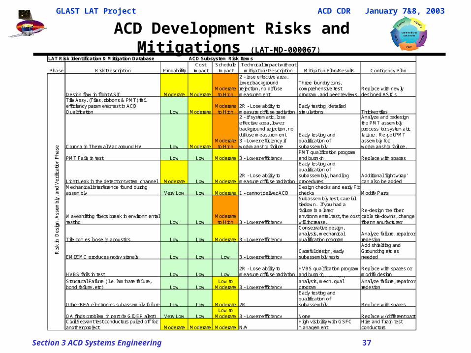
Section 3 ACD Systems Engineering 37
ACD Development Risks and Mitigations (LAT-MD-000067)
LAT Risk Identification & Mitigation Database ACD Subsystem Risk Items
Phase Risk Description ProbabilityCost
ImpactSchedule
ImpactTechnical Impact without
mitigation/ Description Mitigation Plan/Results Contigency Plan
Design flaw in flight ASIC Moderate ModerateModerate to High
2 - lose effective area, lower background rejection, no diffuse measurement
Three foundry runs, comprehensive test program, and peer reviews
Replace with newly designed ASICs
Tile Assy. (Tiles, ribbons & PMT) fail efficiency parameter test in ACD Qualification Low Moderate
Moderate to High
2R - Lose ability to measure diffuse radiation
Early testing, detailed simulations Thicker tiles
Corona in Thermal Vac around HV Low ModerateModerate to High
2 - if systematic, lose effective area, lower background rejection, no diffuse measurement 3 - Lower efficiency if workmanship failure
Early testing and qualification of subassembly
Analyze and redesign the PMT assembly process for systematic failure. Re-pot PMT assembly for workmanship failure.
PMT Fails in test Low Low Moderate 3 - Lower efficiencyPMT qualification program and burn-in Replace with spares
Light Leak in the detector system channel Moderate Low Moderate2R - Lose ability to measure diffuse radiation
Early testing and qualification of subassembly, handling procedures
Additional 'light wrap' can also be added
Mechanical interference found during assembly Very Low Low Moderate 1 - cannot deliver ACD
Design checks and early Fit checks Modify Parts
Waveshifting fibers break in environmental testing Low Low
Moderate to High 3 - Lower efficiency
Subassembly test, careful tiedown. If you had a failure in a later environmental test, the cost will increase.
Re-design the fiber cable tie-downs, change fiber manufacturer
Tile comes loose in acoustics Low Low Moderate 3 - Lower efficiency
Conservative design, analysis, mechanical qualification program
Analyze failure, repair or redesign
EMI/EMC produces noisy signals Low Low Low 3 - Lower efficiencyCareful design, early subassembly tests
Add shielding and Grounding etc as needed
HVBS fails in test Low Low Low2R - Lose ability to measure diffuse radiation
HVBS qualification program and burn-in
Replace with spares or modify design
Structural Failure ( I.e. laminate failure, bond failure, etc) Low Low
Low to Moderate 3 - Lower efficiency
Conservative design, analysis, mech. qual program
Analyze failure, repair or redesign
Other BEA electronics subassembly failure Low Low Moderate 2R
Early testing and qualification of subassembly Replace with spares
QA finds problem in part (ie GIDEP alert) Very Low LowLow to
Moderate 3 - Lower efficiency None Replace w/ different partCivil Servant test conductors pulled off for another project Moderate Moderate Moderate N/A
High visibility with GSFC management
Hire and Train test conductors
Ris
k in
D
esi
gn
, A
sse
mb
ly,
an
d V
erific
atio
n P
ha
se
GLAST LAT Project ACD CDR January 7&8, 2003
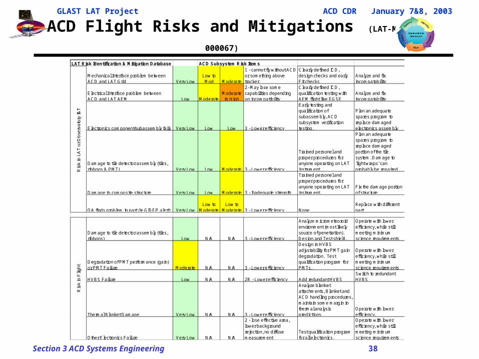
Section 3 ACD Systems Engineering 38
ACD Flight Risks and Mitigations (LAT-MD-000067)
LAT Risk Identification & Mitigation Database ACD Subsystem Risk Items
Mechanical Interface problem between ACD and LAT Grid Very Low
Low to Mod Moderate
1 - cannot fly without ACD or something above tracker
Clearly defined ICD, design checks and early Fit checks
Analyze and fix incompatability
Electrical Interface problem between ACD and LAT AEM Low Moderate
Moderate to High
2- May lose some capabilities depending on incompatibility
Clearly defined ICD, qualification testing with AEM flight like EGSE
Analyze and fix incompatability
Electronics component/subassembly fails Very Low Low Low 3 - Lower efficiency
Early testing and qualification of subassembly, ACD subsystem verification testing.
Plan an adequate spares program to replace damaged electronics assembly
Damage to tile detector assembly (tiles, ribbons & PMT) Very Low Low Moderate 3 - Lower efficiency
Trained personel and proper procedures for anyone operating on LAT instrument.
Plan an adequate spares program to replace damaged portion of the tile system. Damage to 'light wraps' can probably be repaired.
Damage to composite structure Very Low Low Moderate 3 - Inadequate strength
Trained personel and proper procedures for anyone operating on LAT instrument.
Fix the damage portion of structure
QA finds problem in part (ie GIDEP alert) Very LowLow to
ModerateLow to
Moderate 3 - Lower efficiency NoneReplace with different part
Damage to tile detector assembly (tiles, ribbons) Low N/A N/A 3 - Lower efficiency
Analyze micrometeoroid environment (most likely source of penetration). Design and Test shield.
Operate with lower efficiency, while still meeting minimum science requirements
Degradation of PMT performance (gain) or PMT Failure Moderate N/A N/A 3 - Lower efficiency
Design in HVBS adjustability for PMT gain degradation. Test qualification program for PMTs.
Operate with lower efficiency, while still meeting minimum science requirements
HVBS Failure Low N/A N/A 2R - Lower efficiency Add redundant HVBSSwitch to redundant HVBS
Thermal Blanket Damage Very Low N/A N/A 3 - Lower efficiency
Analyze blanket attachments, Blanket and ACD handling procedures, maintain some margin in thermal analysis predictions
Operate with lower efficiency.
Other Electronics Failure Very Low N/A N/A
2 - lose effective area, lower background rejection, no diffuse measurement
Test qualificaiton program for all electronics.
Operate with lower efficiency, while still meeting minimum science requirements
Ris
k in
LA
T o
r O
bse
rva
tory
I&T
Ris
k in
Flig
ht
GLAST LAT Project ACD CDR January 7&8, 2003
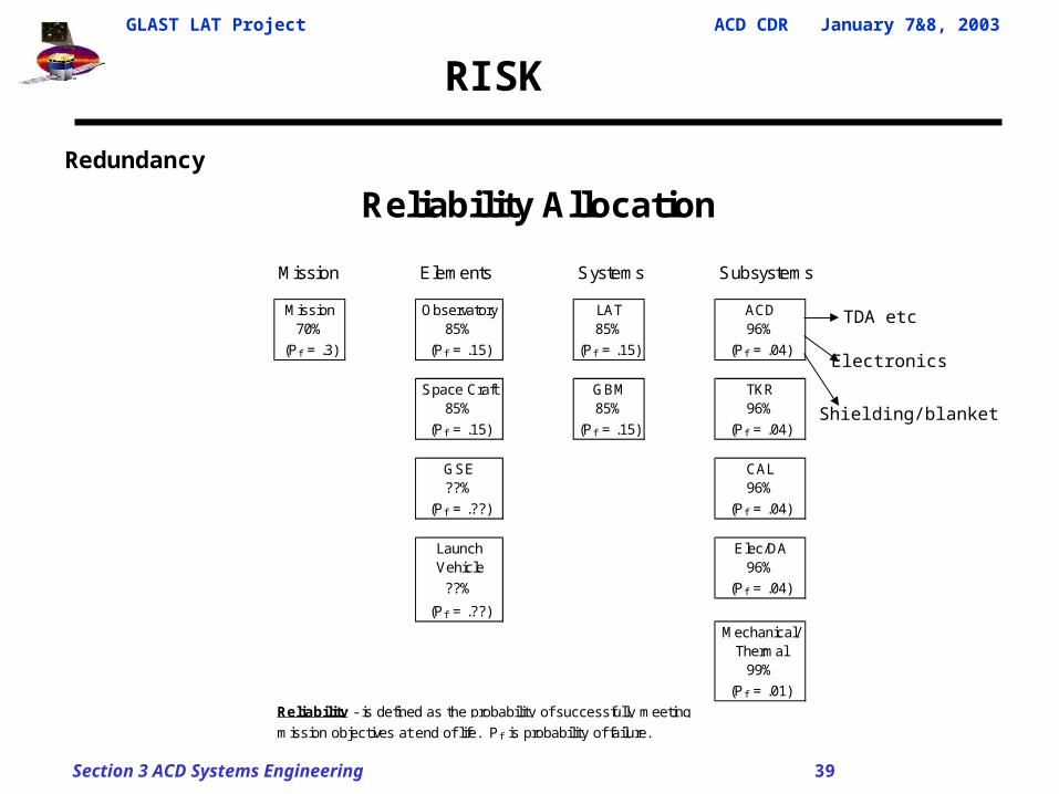
Section 3 ACD Systems Engineering 39
Redundancy
Reliability Allocation
Mission Elements Systems Subsystems
Mission Observatory LAT ACD70% 85% 85% 96%
(Pf = .3) (Pf = .15) (Pf = .15) (Pf = .04)
Space Craft GBM TKR85% 85% 96%
(Pf = .15) (Pf = .15) (Pf = .04)
GSE CAL??% 96%
(Pf = .??) (Pf = .04)
Launch Elec/DAVehicle 96%
??% (Pf = .04)
(Pf = .??)
Mechanical/Thermal
99%
(Pf = .01)
Reliability - is defined as the probability of successfully meeting
mission objectives at end of life. P f is probability of failure.
RISK
TDA etc
Electronics
Shielding/blanket
GLAST LAT Project ACD CDR January 7&8, 2003
Section 3 ACD Systems Engineering 40
TECHNICAL ISSUES
GLAST LAT Project ACD CDR January 7&8, 2003
Section 3 ACD Systems Engineering 41
Technical Issues and StatusTechnical Issues and Status
Technical Issues and Requirement Non-compliance *
• Electronics Chassis Packaging – Progress continues to be made on finalizing BEA electro-mechanical packaging design. STATUS and RESOLUTION - Structure design/analysis is fairly complete, some tweaks due to analysis have just been completed. May relax some tight fits on harness to reduce assembly risk. Had to wait for side stay clear growth sign off to consider this. See issue below.
• Potential BEA connector side stay clear violation (ICD/IDD, Level III, 5.22) – LAT Connectors could, depending on tolerance stack up, extend slightly into stay clear. STATUS and RESOLUTION - Changed to lower profile connector and pushed connector rear harness dimensions down. Design now fits into old stay clear with no margin. LAT pursued 1cm expansion of side stay clear with spacecraft vendor and project office. Agreed to by all parties and now reflected in version of IDD currently in sign off. This will allow for margin, relaxation of tight fits and potential expansion of harness size based on engineering model results. Stay clear issue is Fully Resolved.
• Analog ASIC design * (see electrical presentation) - We have caught a variety of problems in the analog ASIC design. Some functions were not working. Design has been updated.STATUS and RESOLUTION –We have solved most of the problems and modified the design for latest fab runs. We have received additional SLAC expertise and asked for some GSFC expertise to help with final design updates and more importantly to help us test for future ones in a more reliable way.
• 5 Year Reliability * (Level III 5.13, 5.14 & 5.4), Our overall 5 year reliability calculations show we are slightly below meeting our Level III efficiency requirement (.92 to .95 vs the .96 req). Other reqs are met at .96 reliability or better.STATUS and RESOLUTION We are revisiting provided numbers and internal margins. We are marginal only in meeting the efficiency req for 5 years, not other requirements. The reliability requirement flow down may have to be reviewed at the GLAST project level.
GLAST LAT Project ACD CDR January 7&8, 2003
Section 3 ACD Systems Engineering 42
Technical Issues and StatusTechnical Issues and Status
Technical Issues and Requirement Non-compliance *
The next two issues involve components that go into determining if we meet our overall efficiency requirements. Changes in these areas had to go through the ACD Instrument science simulation code to see their combined effect on the overall efficiency
• Long Fibers/Efficiency Issue ( Level III, 5.4 ) – The length of some fibers were long, combined with fibers not quite performing as advertised, caused light yield at PMT to not meet requirement for some channels. STATUS and RESOLUTION –Re-mapped the detector to PMT locations, which allowed us to shorten our optical fiber lengths, has been forwarded to LAT which has agreed to change which is reflected in updated ICD currently in signature cycle. Mechanical optimization also complete. Primarily we re-routed the fibers from the outside top and second row tiles on the X side around the corner to FREE cards on the Y side, This change alone has brought our problem side detectors into compliance with individual channel efficiency requirements they needed to meet our overall efficiency requirement. We have also increased the thickness of the top center row tiles to 1.2 cm to improve their performance. Fully resolved.
• Tile Gap/Efficiency Issue * (Level III, 5.4) – The gaps that are needed between tiles reduce the ACD efficiency. The size of gaps are driven by thermal expansion/contraction, tile vibration, and tolerances. STATUS and RESOLUTION -Several solutions particular to certain gaps have been decided on. Acoustic analysis and TDA test results have provided updated minimum gaps which are run through the simulations to update efficiency. The smaller gaps provided in the update make in unlikely additional steps will be needed (for example a reduction on the survival test high temp spec). Will be resolved when simulation results ( expected this week) show ACD meets eff. req. with new gaps (which we expect them to show) and those gaps are fully represented in CAD design
GLAST LAT Project ACD CDR January 7&8, 2003
Section 3 ACD Systems Engineering 43
Technical Issues and StatusTechnical Issues and Status
Technical Issues and Requirement Non-compliance *
• Micrometeoroid shield, (Level IV Req 5.13.5, 5.18.11) – Reduced performance prediction from new analysis model. Related issue, LAT has recently informed us updates to the environment for debris, Micro-meteoroid and Atomic Oxygen has not yet been ‘officially’ defined for the LAT by the project office.STATUS and RESOLUTION - Redesign is in progress which will solve this. (we will have to track the updates in official req flow down before actual implementation)
• Light leaks in TDA and PMT assembly * (Level III, 5.3, 5.2) – Light leak test revealed small light leaks in a bread board TDA.STATUS and RESOLUTION - Fixes to leaks at PMT have been proposed and agreed to. Minor changes in sealing and taping at connector interfaces and tile will be tested for effectiveness. TDA Handling procedure is being created to prevent small punctures.
• Other issues –Development unit PMT failure , we had a development PMT fail after assembly. Evidence points to vac leak. Failure Review Board is currently has created and has implemented a plan to determine exact failure cause. IDD clarifications – IDD still had some tolerance and dimensioning approach clarifications which were very recently worked out. Some ‘growing pains’ for being first LAT subsystem through CDR/Peer Review (i.e. updating some interface documentation ). Tile mount design mechanical peer review input – Lower tile mount slip stick design and angle mount of flexures not yet verified by test.
• Other recently resolved Non compliance Issues – Mass (Level III, 5.19) allocation increased from delta PDR level, Attenuation (Level IV 5.26) calculation updated shows we marginally meet 6% requirement
GLAST LAT Project ACD CDR January 7&8, 2003
Section 3 ACD Systems Engineering 44
SUMMARYSUMMARY
• Accounting and tracking of requirements is well defined.
• Requirements flow and relationships are well defined.
• We have showed our major system interfaces.
• Systems and interface documentation is signed off in the CM system or has entered that final process.
• We have discussed our development test work and major trade studies since PDR.
• Our verification approach and tracking is clearly delineated and documented.
• Major risks and risk mitigations are understood.
• A limited number of technical issues must be resolved before the manufacturing readiness reviews in those areas.
• Approaches to addressing those issues are identified.
GLAST LAT Project ACD CDR January 7&8, 2003
Section 3 ACD Systems Engineering 45
Backup
GLAST LAT Project ACD CDR January 7&8, 2003
Section 3 ACD Systems Engineering 46
Current Issues and StatusCurrent Issues and Status
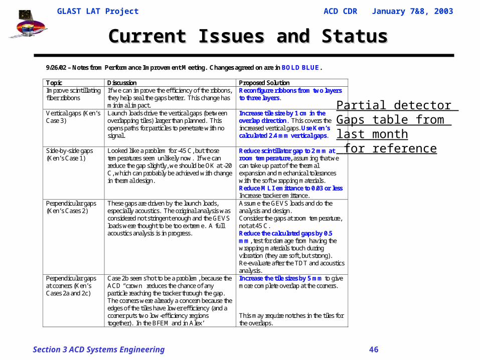
9/26/02 – Notes from Performance Improvement Meeting. Changes agreed on are in BOLD BLUE. Topic Discussion Proposed Solution Improve scintillating fiber ribbons
If we can improve the efficiency of the ribbons, they help seal the gaps better. This change has minimal impact.
Reconfigure ribbons from two layers to three layers.
Vertical gaps (Ken’s Case 3)
Launch loads drive the vertical gaps (between overlapping tiles) larger than planned. This opens paths for particles to penetrate with no signal.
Increase tile size by 1 cm in the overlap direction. This covers the increased vertical gaps. Use Ken’s calculated 2.4 mm vertical gaps.
Side-by-side gaps (Ken’s Case 1)
Looked like a problem for -45 C, but those temperatures seem unlikely now. If we can reduce the gap slightly, we should be OK at -20 C, which can probably be achieved with change in thermal design.
Reduce scintillator gap to 2 mm at room temperature, assuming that we can take up part of the thermal expansion and mechanical tolerances with the soft wrapping materials. Reduce MLI emittance to 0.03 or less Increase tracker emittance.
Perpendicular gaps (Ken’s Cases 2)
These gaps are driven by the launch loads, especially acoustics. The original analysis was considered not stringent enough and the GEVS loads were thought to be too extreme. A full acoustics analysis is in progress.
Assume the GEVS loads and do the analysis and design. Consider the gaps at room temperature, not at 45 C. Reduce the calculated gaps by 0.5 mm, test for damage from having the wrapping materials touch during vibration (they are soft, but strong). Re-evaluate after the TDT and acoustics analysis.
Perpendicular gaps at corners (Ken’s Cases 2a and 2c)
Case 2b seems not to be a problem, because the ACD “crown” reduces the chance of any particle reaching the tracker through the gap. The corners were already a concern because the edges of the tiles have lower efficiency (and a corner puts two low-efficiency regions together). In the BFEM and in Alex’
Increase the tile sizes by 5 mm to give more complete overlap at the corners. This may require notches in the tiles for the overlaps.
Partial detector Gaps table from last month for reference
Recommended