Railway Group Standard
G W R T O ~ ~ 1 Issue One
Date January 1996
Lineside Signals and Indicators
Submitted by
............................................................ Philip Wiltshire Nominated Responsible Manager Synopsis
This standard defines the lineside visual equipment to be used for the signalling of trains. Approved by
............................................................ Robin Nelson Chairman, Train Control and Communications Subject Committee
This document is the property of Railtrack PLC. It shall not be reproduced in whole or in part without the written permission of the Controller, Safety Standards.
Approved by
.......................................m a . . . . . . 3 r . . . . . . . . . . .
Michael Harwood Chairman, Operational Standards Subject Committee
Published by Safety & ~tanclards Directorate Railtrack PLC Floor 2, Fitzroy House 355 Euston b a d London NW I 3AG
Authorised by
............................................................ John Mitchell Controller, Safety Standards Copyright 1996 Railtrack PLC
Signatures removed from electronic version
Withdrawn Document Uncontrolled When Printed

●.
v’
Railway Group Standard
GIVRTO03I
Issue One
Lineside signals and Indicators Date ]anuaw 1996
Page I of 38
Contents
Section
Part A
Part B
1
2
3
4
5
Description Page
Issue record 2
Responsibilities and distribution 2
Compliance 2
Health and Safety Responsibilities 2
supply 2
Purpose
Scope
Definitions
Introduction
4. I Colour and Shape of Aspect and Indication Lights
4.2 Dimensional Tolerances
4.3 Appearance of Rear of Signalsand Indicators
4.4 Flashingl%pects and Indications
4.5 Eyesight Requirements for Tmin Drivers -
4.6 Equipment Performance Requirements
4.7 Speeds at which Aspects and Indications maybe
Considered Readable
Signalsand Indicators
5.1
5.2
5.3
5.4
5.5
5.6
5.7
5.8
5.9
5.10
5.11
5.12
5.13
5.14
5.15
5.16
5.17
5.18
5.19
5.20
5.2 I
5.22
5.23
Colour Light Signal
Colour Light Splitting Distant Signal
Co-Acting Signal
Banner Repeating Signal
Position Light Signal
Junction Indicator
Alphanumeric Route Indicator
Points Indicator (for Tmin Operated Points)
Level Crossing Indicator
Loading/Unloading Indicator
SPAD Indicator
SignalOff Indicator
Right Away Indicator
Close Doors indicator
Barriers Up Indicator
Stop Board
Distant Board
Semaphore Stop Signal
Semaphore Distant Signal
Semaphore Subsidiary Signal
Semaphore Shunting Signal
Buffer Stops on Signalled Routes
Rear of Signal Indications
3
3
3
3
3
3
3
3
4
4
7
7
7
9
13
15
17
[8
20
21
21
22
23
23
24
24
24
25
26
27
28
30
32
34
35
6 Permitted Associations of Aspects and Indications 36
7 References 38
RAIL TRACK I
Withdrawn Document Uncontrolled When Printed
Raihvav GrouD Standard,
GK/RToo3I
Issue One
Date January 1996
Paze 2 of 38
ILinesideSignals and indicators
Part A
kue recordThis standard will be updated when necessary by distribution of a complete
replacement.
Amended or additional parts of revised pages will be marked by a vertical
black line in the adjacent margin.
Issue Date Comments
I January 1996 Initial issue. Supersedes SSP2, GS/STOO03,
SSP4, SSP6 (Sections 5 and 8 only),
GS/STOO08,SSP 13, SSP15, SSP29, SSP44,
SSP45, SSP60,SSP63, SSP67, SSP82 and
JDPCOOI.
Responsibilitiesanddistribution
Controlled copies of this standard shall be complied with by all personnel who
are responsible for the specification, design, installation and testing of lineside
signalsand indicators.
Gm@ianceCompliance with this Railway Group Standard isrequired by6.4.96 for all new or
altered signaling designs. All new or altered installations shall be compliant by
not later than 1.8.96.
Retrospective action is required to make all colour light splitting distant signals
compliant with aspects set out in Section 5.2 by not later than 1.8.97.
When junction indicators are associated with position light subsidiary signals
reading into occupied platform lines, the risksshall be assessedto determine the
need for retrospective action.
Heaith and SafetyRespmsibiiities
In authorizing this Standard Railtrack PLC makes no warmnties, express or
implied, that compliance with all or any of Railway Group Standards is sufficient
on its own to ensure safe systems of work or opetation. Each user is reminded of
its own responsibilities to ensure health and safety at work and its individual
duties under health and safety legislation.
SuppiyControlled and uncontrolled copies of this standard must be obtained from The
Catalogue Secretary, Raikrack Safety & Standards Directorate, Floor 2, Fitzroy
House, 355 Euston Road, London, NW I 3AG.
Telephone 0035903 or 017 I 8305903 (BT)
Facsimile 0035776 or 017 I 8305776 (BT)
2 RAIL TRACK
Withdrawn Document Uncontrolled When Printed

Lineside Signals and indicators
Railway Group Standard
GWRTO03I
Issue One
Date January 1996
Page 3 of 38
1 Purpose
2 scope
3 Definitions
This standard defines the Iineside visual equipment to be used for signaling of
trains in terms of appearance, information conveyed, application and
performance.
This standard deals with application matters only as regards the equipment to be
installed at a given signal location: it does not encompass aspect sequences nor
signalspacing. The manner in which the signalsand indicators are controlled and
monitored by other parts of the signaling system is not covered in this standard.
AXIS (OF SIGNAL OR INDICATOR): an imaginary straight line extending out
from the centre of the display, perpendicular to the plane of the surface of the
display.
STRAIGHTAHEAD ROUTE: the non-diverging, and genemllythe fastest, route
from a junction signal.
4 Introduction4. I Colour and Shape of Aspect and Indication LightsOnly the colours Red, Yellow, Green, White, Signal Red and Black, as defined in
GK/RTOO05 (Safety Related Colours of Signaling Equipment), shall be used for
aspects and indications.
Throughout this standard the term “light” (or “lights”) has been used when
describing the appearance of aspects and indications: unless stated otherwise,
such lights shall be circular in shape.
4.2 Dimensional TolerancesThe dimensions of stop boards, distant boards and semaphore signalsshall be as
defined in this standard, within the following tolerances:
+/- 2 mm for metric measurements;
+/- 0.125 inches for imperial measurements.
4.3 Appearance of Rear of Signals and IndicatorsWhere appropriate, the appearance of signals and indicators from the rear is
specified in this standard.
4.4 FlashingAspects and IndicationsWith the exception of the Level Crossing Indicator, all aspects and indications
which are required to flash shall do so at a frequency of 80 (* 10) flashes per
minute. In each cycle the time for which the display is illuminated shall equal the
time for which it is suppressed.
The Level Crossing Indicator shall flash at a frequency of 120 (A 6) flashes per
minute. In each cycle the display shall be illuminated for 25 milliseconds.
RAIL TRACK 3
Withdrawn Document Uncontrolled When Printed

Railwav GrouD Standard
Issue One
Date January 1996 Lineside Signals and indicatorsPage 4 of 38
4.5 Eyesight Requirements for Train DriversThe signals and indicators defined in this standard are intended to be read by
drivers meeting the eyesight requirements of Group Standard GO/RT3251
(Safety Requirements for Tmin Drivers).
4.6 Equipment Performance Requirements4.6. I GeneralThe key requirement for any signal or indicator is readability within a defined
3-dimensional space. For most signal and indicator types this is expressed in
terms of a requirement for a narrow beam readable tange, and a requirement
for wide angle readability at short range. In each case the summation of all such
requirements describes the space within which the signal shall be readable
when considering the application of signalsand indicators it shall be assumed that
they are not readable at any points outside this space. Note, however, that when
signals and indicators are installed at agiven location they need not necessarily be *
readable (or even visible) from all positions described in the performance
requirements - the requirements for sighting of signals at specific locations are
laid down in GK/RTO037 (Signal Sighting).
4.6.2 MountingSignals and indicators shall be rigidly mounted to ensure that they do not deflect
from their designed alignment under any reasonably foreseeable wind loading.
4.6.3 ReadabilityAll signalsand indicators shall be readable in clear conditions by day and by night,
at all points demanded by their equipment performance requirements. (Clear
conditions shall be taken to mean daylight visibility of 1000m or better, where
visibility is measured in accordance with recognised guide lines, such as those
contained in the British Meteorological Office Observer’s Handbook).
An aspect or indication shall only be considered “readable” at a given point if
persons meeting the eyesight requirements of Section 4.5, are satisfied that it is
so. The equipment approval process shall include confirmation of readability by
a representative sample of such persons. To allow for degradation in service, and
variations in power supply, equipment shall only be considered satisfactory m
when conducting approval tests, if it isreadable at a range 250/o greater than the
required range stated in the appropriate performance category definition.
The brightness levels of aspects and indications shall besuchthat where different
types may be associated, no one aspect or indication shall overpower another.
This condition shall be considered satisfied only when the performance
requirements of each aspect or indication can be met when displayed in
association with any legitimate combination of other aspects or indications.
The visual environment in which signalsand indicators are located, in particular
the background against which they are viewed and highly contrasting areas of
brightness and deep shadow on the approach, can have a significant effect on
readabili~.
In difficult visual environments additional measures such as large backboards and
extended hoods may be required to ensure readability under all conditions. An
individual signalor indicator will only be considered to meet the requirements of
this standard when it is readable under all local lighting conditions.o
4 RAIL TRACK
Withdrawn Document Uncontrolled When Printed

RaitwayGroup Standard
GK/RToo3I
Issue One
Lhmside Signa[s and Indicators Date January 1996
Page 5 of 38
4.6.4 Definitions of Performance Categories4.6.4. I Category 1- Long range
(a)
(b)
(c)
All aspects/indications shall be readable, at angles to the axis of up to 5”, at
distances up to 300 metres; and at anglesto the axis of up to 30 at distances
between 300 and 800 metres.
k shall be possible to configure the signal/indicator such that all its
aspects/indications remain readable as it is approached (along any line of
approach parallel to, and within a3 metre radius of, the axis), up to a point 2
metres on the approach side of the signal.
All lights of all aspects/indications displayed simultaneously shall appear to
be of equal intensity.
4.6.4.2 Category 2- Medium Range
(a) All aspedindicationsshall be readable, atanglestothe axisof upto 10°, at
distances up to 250 metres.
(b) Allaspects/indicationsshall be readable, atanglestotheaxisof upto45°,at
distances up to 5 metres.
(c) All lights of all aspects/indications displayed simultaneously shall appear to
be of equal intensi~.
4.6.4.3 Category 3- Short Range
(a) All aspectdindicationss hall be readable, atanglestotheaxisof up to 10“, at
distances up to 100 metres.
(b) Allaspects/indications shall rereadable, atanglestotheaxisof upto45” ,at
distances up to 5 metres.
(c) All lights of all aspects shall appear to be of equal intensity.
4.6.4.4 Category 4- Semaphore
(a) Allaspects/indicationsshall be readable, at anglestotheaxisof up to 10°, at
distances up to 400 metres.
(b) The aspects shall be readable, atanglestotheaxisof upto45”, at distances
up to 5 metres.
(c) Ail lights of all aspects shall appear to be of equal intensity.
,
RAIL TRACK 5
Withdrawn Document Uncontrolled When Printed

Railway Group Standard
Issue One
Date January 1996 Uimside Signals and IndicatorsPage 6 of 38
4.6.5 Standard Performance Requirements for Signals and IndicatorsThe standard performance requirements for each type of signal and indicator
are defined in Table 1.
Signal/Indicator Standard Performance Requirements1
Colour Light Signal Category I (Long Range) or Category 2 (Medium Range) - see Note I
Colour Light Splitting Category I (Long Range) - see Note 1Distant Signal
Co-Acting Signal All signal/indicator types used in a co-acting application shall meet the standardperformance requirements for that signal/indicator type unless agreed otherwise by theSignal Sighting Committee.
Banner Repeating Signal Category 2 (Medium Range) or Category 3 (Short Range) - see Section 5.4.2(Application) for constraints on application.
Position Light Signal Category 3 (Short Range)
Junction Indicator Category I (Long Range)
Alphanumeric Route Category 2 (Medium Range) or Category 3 (Short Range) - see Section 5.7.2Indicator (Application) for constraints on application. Note that the Category 2 and 3 indicators
are referred to as Standard and Miniature Alphanumeric Route Indicators respectively.
Points Indicator (for Train Category 3 (Short Range)Operated Points)
Level Crossing Indicator Category I (Long Range)
Loading/Unloading Catego~ 3 (Short Range)Indicator
SPAD Indicator The indicator shall be capable of attmcting the drivers’ attention, by the action of beingilluminated, at distances up to 100 metres and at angles to the axis of up to 30°.Furthermore, it shall be capable of doing so when on the periphery of the drivers’ vision,and in an environment with other bright background lights.
Signal Off Indicator Category 3 (Short Range)
~ght Away (RA) Indicator Category 3 (Short Range)
Close Doors Indicator Category 3 (Short Range)
Barriers Up Indicator Categoty 3 (Short Range)
Stop Board Dimensions and reflectivity are specified (See Section 5.16. I )
Distant Board Category 2 (Medium Range)
Semaphore Stop Signal Category 4 (Semaphore)
Semaphone Distant Signal I Catego~4 (Semaphore)
Semaphore Subsidiary Category 4 (Semaphore)Signal
Semaphore Shunting Signal Category 3 (Short Range)
Buffer Stop Lights Catego~ 3 (Short tinge)1
Rear of Signal Indications Category 3 (short Range)
Table 1
.
0
I
Notes: I In the cases identified, an additional requirement is that where
multiple lights are displayed these shall be separately distinguishable as such
throughout the space defined by the performance category.
6 RAi LTRACK
Withdrawn Document Uncontrolled When Printed

IMway Group Standard
GIURTO03I
Issue One
Lineside signals and Indicators Date janua~ 1996
,, Page 7 of 38
4.7 Speeds at which Aspects and Indications may be ConsideredReadableThe maximum speed at which an aspect or indication may be considered
readable is determined by the available sighting distance, and the minimum
sighting time requirements defined in GK/RTO037 (Signal Sighting). The limits
defined in Sections 4.7. I to 4.7.4 are absolute maxima, based on the assumption
that thesightingdistance of theaspecthdication will be no lessthan the readable
range defined in the relevant Performance Category (see Section 4.6.3); in any
individual case it is necessary to consider the sighting distance which is actually
available.
4.7. I Performance Category I EquipmentAll equipment meeting the requirements of Performance Category I (see
Section 4.6.4), may be considered readable at speeds up to 125 mph.
4.7.2 Performance Category 2 EquipmentWith the exception of the Banner Repeating Signal, equipment which meets the
requirements of Performance Category 2 may be used only where train speeds
do not exceed 80mph. The Banner Repeating Signal may be used for tmin
speeds up to 125mph, since it is not necessary for the driver to act upon the
aspect displayed unless a caution aspect has been displayed at the previous main
signal.
4.7.3 Performance Category 3 EquipmentWith the exception of ground position light signals which are preset by a main
route, equipment which does not exceed the requirements of Performance
Category 3 (see Section 4.6.4) maybe used only where there is no requirement
for the aspect/indication to be read at a speed exceeding 15 mph. For this
purpose, it maybe considered that 1S mph will not be exceeded by
movements contained within the confines of a yard or siding
movements starting from rest, drawing to a halt at a main stop aspect, or
proceeding under the authority of a position light aspect.
Ground position light signals which are preset by a main route may be
considered exempt from the limit of 15mph, and maybe used at line speeds.
4.7.4 Performance Category 4 EquipmentSemaphore main signals may be considered readable at speeds up to 100 mph.
5 Signalsand Indicators5. I Colour Light Signal5. [. I DescriptionAcolour light signal isa running signalwhich displays its aspects only by means of
Red, Yellow and Green coloured lights.
Note: The statements in the following paragraph do not apply to COLOUR
UGHTSPU~lNGDISTANTSIGNAM or CO-ACTING SIGNA& special conditions
apply to these types of signal and they are dealt with in Sections 5.2 and 5.3
respectively.)
Each signal shall display only one of the aspects defined in Table 2 at a time. No
other aspects maybe displayed. An aspect shall be displayed at all times. A signal
may be configured to be capable of showing any of the permitted aspects, with
the exception that no signal shall be able to show both single and double flashing
yellow aspects.
RAIL TRACK 7
Withdrawn Document Uncontrolled When Printed

Railway Group Standard
GK/Rl@~~i
Issue One
Date Januaty 1996
Pa~e 8of38
LinesieleSignals and Indicators
Figure I
Dimensions only advisory
T-*
202MIN DIASIGNALLIGHTAPERTURES
FRONTCOLOURBLACK
Aspect Description Description Meaning to Driver
Red light or no light Danger stop.
One yellow light Caution Be prepared to stop at the next signal.
Two yellow lights Preliminary caution Be prepared to find the next signal exhibiting one yellow light.displayed vertically
One flashing yellow light Preliminary caution Be prepared to find the next signal exhibiting one yellow lightwith junction indication for diverging route(s).
Two flashing yellow lights Indication of Next signal exhibiting one flashing yellow light.displayed vertically diverging route
ahead of next butone signal
Green light Clear Next signal exhibiting a proceed aspect.
Table 2
5. I.2 ApplicationSignal heads comprising more than one light shall normally be mounted
vertically. A signal head maybe mounted at another angle provided:
(a) The performance requirements of Section 4.6.4 can be met under such
circumstances.
AND
.
r
(b) That any double yellow aspect continues to be vertically displayed.
Wherever possible signalsshall be positioned at or above drivers’ eye level.
8 RAIL TRACK
Withdrawn Document Uncontrolled When Printed

Railway Group Standard
GWRTO031
Issue One
Lineside signals and Indicators Date ]anua~ 1996
Page 9 of 38
If more than one light isused to display aspects, the normal order of proximi~of
lights to the axis of the driver’s eye shall be as follows:
1. red aspect light closest
2. first yellow aspect light (the one which is alight for a single yellow
aspect or flashing single yellow aspect)
3. green aspect light
4. second yellow aspect light (required only for double yellow aspect)
Where any of the four lights mentioned above are not provided, or are
combined into a single unit, the order described above shall be maintained by the
remaining lights.
k is permitted to deviate from the above requirements to enable the use of
signalsdesigned for use only in tunnels which would not otherwise be capable of
displaying readable double yellow and flashing double yellow aspects (as
required by Section 4.6.4). In such cases the two yellow aspect lights may be
separated by both the red and green aspect lights.
There may also be deviation from the normal arrangement of aspect lights in the
case of splitting distant signals (see Section 5.2).
Co[our light signal heads shall be painted matt black as seen from trains to which
the signal applies and the remainder of the head shall be painted silver.
5.2 Colour Light Splitting Distant Signal5.2. I DescriptionAcolour light splitting distant signal consists of two or more associated COLOUR
LIGHT SIGNAL heads. The aspect displayed by each signal head shall relate to
only one route at the junction signalahead, thereby conveying route information
to the driver.
A splitting distant signal may also act as a stop signal, in which case only one signal
head shall display a red aspect. At combined stop and distant signals any signal
head with no red aspect shall only be lit when a route to which that signal head
applies is set beyond the junction signal.
In exceptional circumstances an outer splitting distant signal maybe provided.
Note: throughout this standard the term splitting distant signal, without
further qualification, applies to both inner and outer splitting distant signals.Any
reference to an inner splitting distant signal applies equally to the only splitting
distant signal where an outer splitting distant signal is not provided. Outside the
context of this standard, however, the prefix inner need not be used when
referring to a splitting distant signal at locations where there is no outer splitting
distant.)
.
Inner splitting distant aspects shall be displayed in accordance with the following
principle5
(a) Whenever the inner splitting distant signal is cleared while the junction
signal to which it applies is at Danger, a yellow light shall be displayed only
by the inner splitting distant signal head capable of displaying a red aspect.
RAILTRACK 9
Withdrawn Document Uncontrolled When Printed

Railway Group Standard
GIURTO03I
Issue One
Date January 1996 Lineside Signals and l!ndicatorsPage 100f38
(b) When a forward route isset at the junction signal the inner splitting distant
signal head for that route shall show the aspect appropriate to the
conditions ahead. All other inner splitting distant signal heads which apply
to that junction signal shall show a single yellow aspect.
(c) The position of the less restrictive inner splitting distant aspect relative to
the yellow aspects of the other inner splitting distant signal heads shall
convey the following information:
the direction of the route shall be indicated by the relative horizontal
positions of the aspects;
the speed of the route shall be indicated by the relative heights of the
aspects. o
(d) An inner splitting distant signal shall not be equipped to display a flashing
single yellow aspect.
The use of outer splitting distant signalsisonly permitted where the approach to
a red aspect displayed by the corresponding junction signal is signalled (in
accordance with GK/RTO032 [Lineside Signal Apect Sequences]) using the
normal four aspect sequence (ie. double yellow, yellow, red).
Outersplittingdistant aspects shall be displayed inaccordance with the following
principles:
(a)
(b)
(c)
(d)
Whenever the outer splitting distant signal is cleared while the junction
signal to which it applies is at Dange~ a double yellow aspect shall be
displayed only by the outer splitting distant signal head capable of
displaying a red aspect.
When a forward route is set at a junction signal ahead the outer splitting
distant signal head for that route shall show a green aspect. All other outer esplitting distant signalheads which apply to that junction signalshall show a .
double yellow aspect.
The position of the outer splitting distant green aspect relative to the
double yellow aspects of the other outer splitting distant signal heads shall
convey the following information:
the direction of the route shall be indicated by the relative horizontal
positions of the aspects;
the speed of the route shall be indicated by the relative heights of the
aspects.
An outer splitting distant signal shall not be equipped to display a flashing
double yellow aspect.
10 RAIL TRACK
Withdrawn Document Uncontrolled When Printed

●✎
Lineside Signals
Rahvay Group Standard
GK/RT003 I
Issue One
Date January 1996
Paze I I of 38
Permissible combinations of aspects are shown in Table 3, Table 4, Table 5 and
Table 6. (Note. In Table 3, Table 4, Table 5 and Table 6, the abbreviations R, Y
and G represent signal lights of the colours red, yellow and green, positioned
relative to each other as shown.)
Lighi%which are shown as being horizontally level in the following tables shall be
displayed such that they appear level to an extent sufficient to satisfy the Signal
Sighting Committee.
The horizontal separation between adjacent signal heads is defined in
GKlRTO037 (Signal Sighting).
Aspect Arrangement Meaning to Driver I
R stop
Y Caution
I YYY
Preliminary Caution (lower speed divergence to left at junction signal)
I Y Preliminary Caution (straight ahead route set at junction signal)YY
Y Clear (lower speed divergence to left at junction signal)G
G Clear (straight ahead route set at junction signal)Y
Table 3 Inner Splitting Distant for Single Diverging Route to Left
Aspect Arrangement
YY
I YGY
I YGY
Meaning to Driver
stop
Caution
Preliminary Caution
Clear (lower speed divergence to left at junction signal)
Clear (straight ahead route set at junction signal)
Table 4 Outer Splitting Distant for Single Diverging Route to Left
RAIL TRACK II
Withdrawn Document Uncontrolled When Printed

fWway Group Standard
GK/Rtio~ [
Issue One
Date January 1996 Lineside Signals and IndicatorsPage 120f38
Aspect Arrangement Meaning to Driver
R stop
Y Caution
‘f’f Preliminary Caution (lower speed divergence to right at junctionY signal)
Y Preliminary Caution ( sttaight ahead route set at junction signal)Yy
Y Clear (lower speed divergence to right at junction signal)G
G Clear (straight ahead route set at junction signal)Y
Table 5 Inner Splitting Distant for Single Diverging Route to Right
Aspect Arrangement Meaning to Driver 1
R stop
Y Caution
Y Prelimina~ CautionY
Y Clear (lower speed divergence to right at junction signal)YG
GY Clear (straight ahead route set at junction signal)Y
Table 6 Outer Splitting Distant for Single Diverging Route to Right
Signaling other combinations of left and Fight divergences with splitting distant
signals shall be avoided wherever possible.
5.2.2 ApplicationOuter splitting distant signals shall be provided wherever an inner splitting
distant alone would not provide sufficient advance warning of a divergence for
either of the following purposes:
to enable the necessary reduction in speed to meet the speed restriction of
a turno~
.
9.
.
OR
to enable a train which was being misrouted to be stopped before the
junction signal, where the misrouting of trains would cause significant
operational inconvenience.
in order to prevent illogical aspect sequences, the junction signal shall be
approach controlled from red for all routes which are not provided with a
splitting distant signal head; when such a route isset from the junction signal,the
inner splitting distant signal shall display the caution aspect.
At a splitting distant signal all signal heads shall be of the same equipment type.
o
12 RAIL TRACK
Withdrawn Document Uncontrolled When Printed
GIVRTO03I
●*
.
Issue One
Lineside ~ignak and Indicators Date January [996
Page 130f38
All aspects displayed at a splitting distant when no route is set from the
corresponding junction signal shall be displayed by the signal head which relates
to the straight ahead route at the junction signal. Where a splitting distant isitself
a junction signal, the appropriate route indication shall be displayed. Wherever
practicable, the signal head relating to the straight ahead route shall be
positioned horizontally closesttothe driver in the case of a splitting distant signal
for a right hand divergence a special structure shall normally be provided to
enable this requirement to be met.
5.3 Co-Acting Signal5.3.1 DescriptionA co-acting signal repeats the aspects of a main signal.
Where a co-acting signal is provided, the signal which is nearest to the normal
position for a signal (as defined in GK/RTO037 [Signal Sightingl) shall be
considered the primary signal.
The main aspects and associated indications of the co-acting signal shall be the
same as those of the primary signal. If any other aspects and indications of the
primary signalare repeated by the co-acting signal they shall also be the same as
those of the primaty signal.
The size and relative positions of the aspects and indications of a co-acting
signal may differ from those of the primary signal.
5.3.2 ApplicationCo-acting signalsmay be used at line speeds of up to 125mph.
Criteria for Abdication
Co-acting signalsshall only be provided where all of the following conditions are
met:
(a)
(b)
(c)
(d)
It is not possible to position the primary signal so that it is continuously
visible (ignoring interruptions considered negligible by the Signal Sighting
Committee) to the drivers of all types of tmin, from the sighting point
defined in GK/RTO037 (Signal 5ighting) to within 2 metres of the signaL
There is an operational requirement for the driver to be informed of the
exact aspect of the signal, thereby rendering a BANNER REPEATING
SIGNAL inadequate.
The SignalSightingCommittee confirms the need foraco-acting signaland
this is approved by the Infrastructure Controller.
The primary signal is not a splitting distant signal.
RAIL TRACK 13
Withdrawn Document Uncontrolled When Printed

Railway Group Standard
GK/RT()()~ i
Issue One
Date January 1996 Lineside Signals-and indicatorsPage 140f38
Abdication Requirements
Where a co-acting signal is required the following principles shall be complied .with:
(a)
(b)
(c)
(d)
(e)
(9
(g)
(h)
The co-acting signal shall be positioned to ensure that the combination of .primary and co-acting signals provides continuity of readability from the
sighting point defined in GK/RTO037 (Signal Sighting) to within 2 metres of
the required stopping point.
The co-acting signalshall be positioned no more than 5m from the primary
signal on the axis parallel to the track, and no more than 2m from the
primary signal on the axis perpendicular to the track.
The co-acting signal shall not be positioned beyond the insulated rail joint oor other limiter of the tmck section which replaces the signal.
The position and orientation of both primary and co-acting signalsshall be
such that neither signal can be mistaken as applying to an adjacent line.
The co-acting signal shall be controlled to the same main aspect as the
primary signal. Main routes up to the signal shall require both signals
proved alight.
The Infrastructure Controller shall assess the risks of non-provision of
position light aspects (and associated route indications) on the co-acting
signal; these aspects and indications shall be provided only where the risk
assessment indicates that they are necessary.
AspectSand indications which may reassociated with the main colour light
aspect of the co-acting signal shall include all those permitted for the
COLOUR LIGHT SIGNAL (see Section 6 for permitted aspect/indicationo
associations).*
A RIG1-/TAWAYlND/CATOR or CLOSEDOORS INDICATOR, if required, shall
normally be provided at either the primary or the co-acting signal -
whichever provides the best sighting from a train starting from the.
platform. They shall only be provided at both signalsif this is considered
necessary by the Signal Sighting Committee to cater for trains of different
type or length.
14 RAIL TRACK
Withdrawn Document Uncontrolled When Printed

GKIRTO03I
.
.
Issue One
Lineside Signals and Indicators Date ]anua~ 1996
Page 150f38
5.4 Banner Repeating Signal5.4.1 DescriptionA banner repeating signal indicates whether the signal ahead is ON or OFF
Banner repeating signals shall consist of a rectangular unlit, or black, bar
displayed against a background illuminated with white light. The proportions
shall be as shown in Figure 2 where the white light is directly tmnsmitted (eg
fibre optic devices). Where the white light is reflected or used to silhouette a
banner arm, the white area may be increased provided the signal meets the
requirement of Section 4.6.3.
K““
%’?g
m
\
ILLUMINATED
/
“*7?
WHITEsom
Figure 2 Banner Repeating Aspect
The aspects displayable shall be as shown in Table 7.
[ Aspect Description Meaning to Driver
Horizontal arm ON Be prepared to find the related signal at Danger
Arm at an upper OFF Related signal is exhibiting a proceed aspectquadrant angle of450
Table 7
RAIL TRACK 15
Withdrawn Document Uncontrolled When Printed

Railway GrouD Standard
Issue One
Date January 1996 Lineside Signals and indicatorsPage 160f38
Two banner signal heads may be combined to form a splitting banner repeating
signal. Splitting banner signalswith more than two banners are not permitted.
Centre to centre distance between the two banners of a splitting banner
repeating signal shall be 10OOmm in the horizontal and 500mm in the vertical.
A splitting banner signal head shallonly clear when the related signal iscleared for
the route(s) to which it refers; it shall remain in the ON position at all other
times. The higher splitting banner head shall refer to the straight ahead route,
which shall always be the fastest route (otherwise a splitting banner signal is not
permitted); the lower splitting banner head shall refer to a diverging route (or
routes). The horizontal position of the lower splitting banner signal head
(relative to the higher banner head) shall indicate the direction of the diverging
route(s) relative to the straight ahead route.
The splitting banner head for the straight ahead route shall not clear for any
other route. The splitting banner head for a diverging route may clear for more ethan one diverging route, provided all routes to which it refers have the same
permissible speed, diverge from thestraightahead route through the same set of
points, and do not differ in any other characteristic which may have a bearing on
safety or operational efficiency (such as provision of electrification).
5.4.2 ApplicationBanner repeating signals shall only be provided where the available sighting of
the main signal is inadequate and cannot reasonably be improved. Inadequate
sighting shall be considered to include situations where:
(a)
OR
(b) “
OR
(c)
OR
(d)
The
A signal isfrequently approached at danger and, in order to reduce delay it
isdesirable to advise the driver that the signal has cleared before the driver
can see the main aspects.
The required viewing time for the signal is unattainable at the speed of a
train braking to stop at the signal.
.
There have been particular difficulties in drivers misjudging or disregarding
the main signalwhich have resulted in repeated incidents of the signal being
passed at danger. Such applications should be exceptional..
Local conditions are such that it is reasonable to predict that the problems
described in (c) are likely to occur.
banner repeating signal shall be positioned on the approach to the main
signal such that the required sighting time for the main signal is provided. The
main signal shall normally be visible to the driver before passing the banner
repeating signal so that the driver is continuously informed of the state of the
main signal from the position at which the banner is first sighted until the tmin
reaches the main signal.
If a banner repeating signal is provided for a platform starting signal it may oadditionally perform the function of an OFF INDICATOR, provided it is suitably
positioned.
16 RAIL TRACK
Withdrawn Document Uncontrolled When Printed

Railway Group Standard
GIVRTO03 I
Issue One
o.
,
Lineside Signa!s and indicators Date ]anuary 1996
Page 17 of 38
Banner repeating signals meeting performance category 2 shall normally be
used; where it is necessary to use a banner repeating signal which only meets
performance category 3 it shall be ensured that sighting requirements can be
adequately met.
In situations where all trains start from rest (from a terminal or bay platform) an
OFF Indicator (see Section 5. 12)maybe used in lieu of a banner repeating signaL
Splitting banner repeating signals shall only be used where:
(a) A banner repeating signal is required on the approach to a junction signal
AND
(b) k isnecessatyto distinguish between an OFF banner aspect forthestraight
ahead route and an OFF banner aspect for any other route.
5.5 Position Light Signal5.5.1 DescriptionA position light signal displays its aspects by means of the position and colour of
lights. The aspects which maybe displayed are shown in Table 8. A back marker
light shall be provided when specified by the Signal Sighting Committee.
Aspect Description Meaning to Driver
Two red lights, or one red and one On (Red) stopwhite light, horizontally displayed ITwo yellow lights, or one yellow and On (Yellow)one white light, horizontally displayed
No aspect (where associated with a On (No Light)main aspect)
Two white lights displayed at an upper offquadrant angle of450
Stop (applies to movements in thedirection(s) for which the signal can becleared: other movements may pass thissignal without it being cleared)
Obey main aspect
The line ahead may be occupied. Proceedcautiously towards the next stop signal, stopboard or buffer stops. Be prepared to stopshort of any obstruction. The associated mainaspect (where provided) may be passed atDanger.
Table 8
5.5.2 ApplicationThe form of signal to be used for new installations isthat which displays two red
lights (or exceptionally two yellow lights) for the on aspect.
Signalsdisplaying a red and white (or yellow and white) On aspect shall only be
installed when altering installations where other signalsof this type are to remain
in service at the locality.
Signalsdisplaying two red (or two yellow) lights for the On aspect, except when
employed as a limit of shunt indicator, shall not be used in the same locality as
signalsdisplaying a red and white (yellow and white) for the On aspect.
A locality in this context shall generally be taken to mean a single station or
junction area.
RAIL TRACK 17
Withdrawn Document Uncontrolled When Printed

Railway Grmm Standard
GK/RToo3I
Issue One
Date January 1996 Lineside Signals and lndicatm=sPage 180f38
Position light signalsmay be configured for the applications shown in Table 9. In
each application the signalshall be equipped to display only the aspects shown in
Table 8.
Application Aspects Displayable
Limit of shunt 1. On (TWO Red lights) only
Position light shunting signal (red normal aspect) 1. On (Red)2. off
Position light shunting signal (yellow normal I. On (Yellow)aspect) 2. off I. .
Position light associated with a main aspect 1. On (No Light)2. off
Table 9
The position light signal with yellow on aspect shall only be used in exceptional
circumstances.
The only form of route indication which maybe associated with a position light
aspect is that displayed by a miniature ROUTE INDICATOR, which must be
immediately adjacent to the signal to which it applies.
Position light signals associated with a main aspect shall normally be mounted
beneath the associated COLOUR LIGHT SIGNAL.
Position light shunting signalsmay be positioned at driver’s eye level if required
for sighting reasons.
When a position light signal ispositioned more than I m above ground level then
each light shall be fitted with a long hood, in order to prevent phantom aspects
due to internal reflection of incident light.
The provision of two or more position Iightsignals together for routing purposes
is not permitted.
5.6 Junction Indicator5.6. I DescriptionA junction indicator indicates route by the angle at which a line of lunar white
light points is displayed. All permitted angles are shown in Figure 3.
Po8moNl
*
Po8m#’44
P0WnUN2 POWllONs
PU8.mON3 PCMl10N6
Figure 3 Junction Indications
*
●
18 RAIL TRACK
Withdrawn Document Uncontrolled When Printed

Railway Group Standard
Gtc/RToo3I
Issue One
o
Lineside signals and Indicators Date January 1996
Page 190f38
All permitted indications are shown in Table 10 and Table I I.
Each junction indicator may be equipped to display any required combination of
indications, subject to the restrictions of Section 5.6.2. Only one indication shall
be displayed by an indicator at a time. An indication shall only be displayed when
the controls for the associated signal permit it to display a proceed aspect.
Wherever there would otherwise be potential for confusion, only the
indications shown in Table 10 shall be displayed.
Indication Meaning to Driver
I No indication, signal ON 10bey main aspect II No indication, signal OFF 10beymain aspect, straight ahead route is set I
Position I indication, signal OFF Obey main aspect, expect divergence to left
Position 4 indication, signal OFF Obey main aspect, expect divergence to ri~ht
Table.1O
The use of the indications shown in Table I I isonly permitted where the layout
is clear and unambiguous to the driver.
I Indication I Meaning to Driver I
Position 2 indication, signal OFF Obey main aspect, expect divergence to left moreextreme than that for position I indication
Position 3 indication, signal OFF Obey main aspect, expect divergence to left moreextreme than that for position 2 indication
Position 5 indication, signal OFF Obey main aspect, expect divergence to rightmore extreme than that for position 4 indication
Position 6 indication, signal OFF Obey main aspect, expect divergence to rightmore extreme than that for position 5 indication I
Table I I
%6.2 ApplicationJunction indicators shall normally be used in association with COLOURLIGHTSIGNA13for simple divergencies to the left or right.
Normally no indication shall be given for the straight ahead route. Routes which
diverge from the straight ahead route shall be indicated in the manner shown in
Figure 4.
Figure 4 Examples of Junction Indications
RAIL TRACK 19
Withdrawn Document Uncontrolled When Printed
Railway Group Standard
GWRTO031
Issue One
Date January 1996 Lineside Signals and indicatorsPage 20 of 38
Where no straight ahead route exists a junction or route indicator shall be
provided for all routes.
To avoid the risk of misreading, junction indicators shall be positioned above the
main aspect, except in exceptional circumstances as recommended by Signal
Sighting Committee.
5.7 Alphanumeric Route Indicator5.7. I DescriptionAn alphanumeric route indicator indicates route using numbers or letters (or a
combination of numbers and letters). The display shall be illuminated and the
colour of light shall be white.
Only the chamctersshown below maybe used; no other symbols are permitted.
ABC DE FGHKLMNPRSTUWXYZ
1234567890
The character font shall be Gill Saris Light.
Where more than one character is used in an indication, the minimum distance
between the outermost points on adjacent characters shall be 20°A of character
height.
No indication shall be given unless the signal with which the indicator is
associated is cleared.
Only one indication at a time shall be visible to the driver.
Alphanumeric route indicatom meeting performance category 2 are termed
standard alphanumeric route indicators, and those which meet only
performance category 3 are termed miniature alphanumeric route indicators
(see Section 4.6.4 for performance requirements).
5.7.2 ApplicationThe indications used shall appear logical to the driver as a description of route.
Preferred and prohibited indications are given in GK/RTOO04(Symbols for Plans
and Sketches). o
When a route indicator is provided for a main signal an indication shall be
displayed for each route from the signal, except where the permitted speed for
the stm”ght ahead route is more than 10 mph above that for any other. In such
cases no indication shall be provided for that route..
When a miniature route indicator is provided for a position light shunting signal
an indication shall be displayed for every route from the signal. When a miniature
route indication isdisplayed for any route from a main signal which isauthorised
by a position light aspect then an indication shall be displayed for every such
route.
The same indication shall be used at all signals which are equipped to show an
indication for a given destination. The use of the same indication on signalsin any
one locality, for different destinations in the same direction, is not permitted.
When used in association with a main aspect, the route indicator shall normally
be positioned to the side of the signal; it may, however, be positioned above or,
exceptionally, below the main aspect where necessaty for sighting or structureo
gauge reasons. When used in association with a position light shunting signal, the
miniature route indicator shall normally be mounted above the signal.
20 RAIL TRACK
Withdrawn Document Uncontrolled When Printed

Railway Group Standard
GIVRTO03I
Issue One
Lineside signals and indicators Date January 1996
Page 21 of 38
When used in association with a semaphore stop signal, the route indicator shall
normally be mounted beneath the semaphore arm.
5.8 Points Indicator (for Train operated Points)5.8. I DescriptionA points indicator informs the driver whether train operated facing points are
correctly closed. The indications shall be as shown in Table 12.
\ Indication I Meaning to Driver I
I Red light I Stop; do not pass over points until they have been secured. I
\ Yellow light I Points are correctly fitting. I
Table 12
5.8.2 ApplicationA points indicator shall be used on the approach to all train operated facing
points, except where a signal is provided.
5.9 Level Crossing Indicator5.9.1 DescriptionA level crossing indicator informs the driver of the correct operation, or
otherwise, of a locally monitored automatic level crossing. The permitted
indications are shown in Table 13.
indication Meaning to Driver -
I Red flashing light or no light I Stow crossing has not operated as required. I
White flashing light Crossing has operated as required; proceed if crossing clear.
Table 13
5.9.2 ApplicationApplication requirements are defined in the Department of Tmnsport Railway
Construction and Operation Requirements for Level Crossings.
RAIL TRACK 21
Withdrawn Document Uncontrolled When Printed

?taihvaYGrouD Standard
Issue One
Date January 1996 Lineside Signals and indicatorsPage 22 of 38
5.10 Loading/Unloading Indicator5.10. I DescriptionLoading/unloading indicators convey instructions to the driver by means of the
position and colour of lights. They are used to control trains in sidings; they do
not give authority for a train to proceed past other lineside signals or out of
sidings. The indications which may be displayed and associated meanings areas
shown in Figure 5. “
9‘s3069
STOP L!AEDLmlY,~wDlsT#N2s FROM‘IHE INDKXIW
PRSPmE m
Note.
\%M-!r/
?
o0
0
/\
o W’mE L@iT
@m Urn-r
.
— —MmEslcwl-YINTl-E htWESiW1-Y IN THE
tawu DmcTIDN FOR owosrrs DlmcT!oNToKMDiffi OR uNLwllu+3 lH4T REWED F@+
LcMmrw m Urumnffi
Figure 5 Loading/Unloading Indications
These indications shall not override any other signal, handsignal or indication
which r.equir~ the driver to stop.
Indicators may be grouped in sets referring to a given line. All indicators in a seto
shall display the same indication at any onetime. Each indicator shall be capable
of displaying all of the indications shown in Figure 5, but shall display no more
than one of these indications at any one time..
All readable indications in a set shall be considered valid by the driver regardless
of their position relative to the train. If the indicators go out while a train isunder
their control the train must stop immediately. Note that the complete set of
indicators at a given location may be extinguished when not in use.
5. I 0.2 ApplicationLoading/unloading indicators shall only be used as an aid to the movement and
positioning of trains; they are not intended to help prevent collision or
derailment of trains, and they shall normally be controlled from the position at
which the loading/unloading operation is supervised, rather than from a
signalbox, ground frame or shunting frame.
A signalcapable of displaying astopaspect, shall protect the running lines beyond
the siding, and no Ioadinghmloading indicator shall be positioned beyond, or
mounted on the same structure as this signal. o
22 RAIL TRACK
Withdrawn Document Uncontrolled When Printed

RaNwaYGrmm Standard
GIURTO03I
Issue One
o.
Lineside signals and Indicators Date ]anua~ 1996
Page 23 of 38
Any loadinghnloading indicators which are positioned within, or direct
movements into, a signalled area shall only be illuminated when the relevant
signalsare displaying a proceed aspect.
Indicators shall be elevated, where practicable, and shall be located at intervals
along the track such that the driver shall have a clear view of at least one indicator
at all times under clear visibility conditions.
5. I I SPAD Indicator5. I I. 1 DescriptionA SPAD indicator displays the illuminated word “STOP”, between flashing red
lights, when the signalto which it applies is passed without authority. The driver
shall understand this indication to mean that the train should be stopped
immediately.
The indicator shall not be illuminated under normal operating circumstances.
The indicator shall be mounted against a backplate, or within a surround, which
shall be coloured blue, as defined in GK/RTOO05 (Safety Related Colours of
Signaling Equipment).
5. I I.2 ApplicationSPAD indicators shall be provided at high risk sites.
The position of the indicator shall be selected to maximise the likelihood of an
unauthorised movement being brought to a stand before reaching any point of
conflict.
It shall therefore be necessa~ to balance the following requirements:
to maximise the length of time for which the driver has the opportunity to
see the SPAD indication after a SPAD has occurred;
to ensure the perceived intensity of the indication is at a high level as soon
as possible after the signal is passed. ‘
The use of a co-acting indicator is permitted if difficulties arise in meeting these
conflicting requirements. No indicator shall be positioned beyond, or within 10
metres of, the first point of conflict beyond the associated signal.
The position of each indicator shall be subject to approval by a signal sighting
committee.
5. I 2 Signal Off Indicator5.12. I DescriptionA signaloff indicator displays an illuminated “OFF” when the signal(s) to which it
applies shows a proceed aspecc it may be double-sided. The colour of light shall
be white and the character font shall be Gill Saris Light. No indication shall be
shown when the signal is at danger. On a hi-directional platform line indications
may be qualified by signsbearing the additional letters “UP”or “DN” according
to the direction of the route set.
5. I 2.2 ApplicationOff indicators shall be provided at station platforms where operational staffwho
are required to see whether trains have authority to proceed cannot otherwise
do so. They shall be positioned such that one isreadable from the location of the
train ready to start and right away operating devices, when provided, and from
all other points at which staff may be positioned when dealing with all types of
train regularly using the platform.
RAIL TRACK 23
Withdrawn Document Uncontrolled When Printed

Railway Group Standard
GK/RToo3I
Issue Onz
Date January 1996 Lineside Signals and IndicatorsPage 24 of 38
On platform lines with intermediate signals, an OFF indication for routes from
the intermediate signal, which read up to the signalat the platform end, may only
be displayed provided the signal at the platform end is also off.
In the circumstances defined in Section 5.4, an OFF indicator may perform the
function of a banner repeating signal.
5.13 Right Away Indicator5.13. I DescriptionA right away indicator displays the illuminated letters “RN when operated by
platform staff, provided the platform starting signal has cleared. The colour of
light shall be white and the character font shall be Gill SarisLight. No indication
shall be displayed unless the associated signal isshowing a proceed aspect. The
driver shall understand this indication to mean that it issafe for him to obey the
main signal aspect.e
5.13.2 ApplicationRight away indicators shall be used where a “ready to start” hand signal is
necessary for some or all of the trains using a platform, but the driver may be
unable to seethe hand signal. The indication shall be readable from the location
of the indicator operating device, and from all points at which trains normally
start (an indicator adjacent to the platform starting signal,where provided, shall
normally be required). Repeat indicators, or a longer range indicator, may be
provided to meet these sighting requirements.
5.14 Close Doors Indicator5.14. I DescriptionA close doors indicator displays the illuminated letters “CD” when operated by
platform staff. The colour of light shall be white and the character font shall be
Gill SarisLight. The driver shall understand the indication to mean that it is safe
for him to close the power operated doors on the train.
5. I 4.2 ApplicationClose doors indicators may be provided at stations with platform staff where
Driver Only trains operate, as an alternative to the provision of CCIV
monitoring equipment or mirrors. o.
5.15 Bawiers Up Indicator5.15. I DescriptionA bamiem up indicator displaysthe illuminated letters “BU” when the associated .barriers are fully raised. The colour of light shall be white and the character font
shall be Gill Saris Light. The driver shall understand the indication to mean that
the operation of raking the barriers at the crossing traversed has been
successful.
5.15.2 ApplicationA barriers up indicator shall be provided only at trainman operated crossings
with barriers. The indicator shall be positioned at a distance beyond the crossing
approximately equal to the length of the longest train which is expected to use
the crossing plus an allowance for the distance covered by the tmin while the
barriers are rising.
24 RAIL TRACK
Withdrawn Document Uncontrolled When Printed

Railway Group Standard
GIVRTO03 I
Issue One
Lineside Signals and Indicators Date January 1996
Page 25 of 38
5.16 Stop Board5.16. I DescriptionA stop board displays a fixed danger aspect and written instructions regarding
the action to be taken after stopping. The colours and permitted dimensions are
shown in Figure 6. Reflectivity performance shall be no worse than that
associated with Class I retro-reflective material (as defined in BS 873 Part 6).
Dimensions only advisoty
c
T
c
It 1c
●.
.
—
stopL!rInL
I
f—
Whistle beforeproceeding
-
:
d
Notes:e
1. ❑ :gp-
■ BLACK.
, ❑ WHITE,
s2.Colour of back9 of sign (including
st.fiening): grey.
1 h 3.Dimensions may
7vary = 50~.
4k 4.Wording on lowerpart of sign may
i vary as required for- specific application.
7k
a b c d e f g h 1 i k I m n x y
Large 1650 900 10 I20 5oa I20 180 I50 20 540 65 65 I30 130 2100 I300Board (rein) (rein)
Medium I300 700 10 I00 404 100 140 I20 20 400 50 50 103 I00 2100 I500Board (rein) (rein)
Small 70(3 400 5 55Board
220 50 80 65 10 210 30 30 60 60 21W 2W0(rein) (rein) (rein)
Figure 6 Stop Board
The meaning to the driver is as follows: stop - do not proceed except in
accordance with the instructions exhibited or on the authority of the authorised
person.
RAIL TRACK 25
Withdrawn Document Uncontrolled When Printed

Railway Group Standard
GK/RToo~ !
Issue One
Date January 1996 Lineside Signals and IndicatorsPage 26 of 38
5. i 6.2 ApplicationThe selectionof the appropriate size of stop board from the 3 types defined in
Figure 6 shall be based on the following criteria
for applications on running lines only the Large and Medium types of board
may be used; the Large type shall be used except where clearance
constraints require the use of the Medium size of board;
for other applications the Medium size board shall normally be used; the
Small board may however, be used to satisfyclearance constraints, and the
Large board may be used to satisfy exceptional sighting requirements.
Stop boards shall be positioned, where possible, on the left hand side of the line,
at the appropriate height and horizontal position indicated in Figure 6.
5.17 Distant Board5. I7. I Description oA distant board displays a fixed caution aspect. Its colours and dimensions shall
be as shown in Figure 7. Reflectivity performance shall be no worse than that
associated with Class I retro-reflective material (as defined in BS 873 Part 6).
1 I I I
l170rml I Notes:
.
c1 1. ❑ YELLOW ❑ WHITE
205mm ❑ BLACK
2. Colour of back of sign(including
Figure 7 Distant Board
stiffening): grey
The meaningtothe driver isasfollows be prepared to stop atthe home signal or
other specified place to which the distant board applies.o
26 RAIL TRACK
Withdrawn Document Uncontrolled When Printed

●.
,
Railway Group Standard
GK/Rl-003 I
Issue One
Lineside Signals and Indicators Date January 1996
Page 27 of 38
5.17.2 ApplicationReflectorised distant boards maybe used to display a caution instruction on the
approach to a COLOUR LIGHT SIGNAL SEMAPHORE STOP SIGNAL, STOP
BOARD, POINTS INDICATOR or buffer stop at the end of a line.
Distant boards shall be positioned, where possible, on the left hand side of the
line, at a height to the centre of the board of 2.5 metres above rail level, and as
close to the running edge as structure gauge clearances permit.
Refiectorised distant boards and semaphore distant signals shall not be
indiscriminately mixed on a single line of route.
5.18 Semaphore Stop Signal5.18. I DescriptionA semaphore stop signal isa running signalwhich displays its aspects by means of
a rectangular semaphore arm by day and coloured lights by night.
The arm shall be co!oured red with a vertical white stripe; its dimensions shall be
as shown in Figure 8 although minor variations to these dimensions are
permitted where-
a) consistency of appearance with other signals in the same locality is
required, and
b) the performance requirements of 4.6.4.4 can still be complied with.
rE SIGNALg ‘m
‘L
POSTEND
FRONT VIEWNote
❑ SIGNAL RED. ❑ BLACK.
❑ WHITE.
178rnm ,- 318 mm7 “ 12.5”
BACK VIEW
Figure 8 Semaphore Stop Signal
RAIL TRACK 27
Withdrawn Document Uncontrolled When Printed

Railway Group Standard
GK/RTOO~I
Issue One
Date January 1996 LimesickSignals and IndicatorsPage 28 of 38
Only the aspects shown in Table 14 shall be displayed.
I Aspect I Description I Meaning to Driver I
I Arm horizontal (visible by day) with red light displayed I Danger I stop I
Arm raised or lowered by angle of450 (visible by day) with Clear Proceedgreen light displayed
Table 14
When a signalconsistsof more than one semaphore stop signal arm each signal
arm shall apply to a single route from the signal. If the signal arms are arranged
directly above one another the position of each arm from top to bottom shall
correspond to the direction of the route from left to right. If the signal arms are
distributed horizontally the position of each arm from left to right shall
correspond to the direction of the route from left to right. In the latter case the osignalarms for routes which differ in speed shall be stepped in heigh~ the highest
arm shall apply to the fastest route and subsequent arms to either side shall be
progressively lower.
5.18.2 ApplicationThe preferred form of signal is the upper quadrant type. The lower quadrant
type shall only be installed where existing lower quadrant signalsare controlled
by the same signal box, or where another signal arm on the same post is of the
lower quadrant type. All signal arms which are mounted on a single structure
shall operate in the same sense (ie. all upper quadtant or all lower quadrant).
When multiple signal arms are arranged vertically above one another they shall
be 1.68 metres (5’6”) apart. This form of junction signal shall only be used where
the speed differential between the fastest and slowest route is no greater than
10mph and where the permitted approach speed is no greater than 40mph.
When junction signal arms are horizontally distributed they shall be i .83 metres
(6’0) apart in the horizontal, and stepped in height in 0.76 metres (2’6”)
increments.
5.19 Semaphore Distant signal .
5.19. I DescriptionA semaphore distant signal isa running signalwhich displays its aspects by means
of a semaphore arm by day and coloured lights by night. .
The arm shall have a fish-tail end and shall be coloured yellow with a black
chevron; its dimensions shall be as shown in Figure 9 although minor variations
to these dimensions are permitted where:
a) consistency of appearance with other signals in the same locality is
required, and
b) the performance requirements of 4.6.4.4 can still be complied with.
28 RAIL TRACK
Withdrawn Document Uncontrolled When Printed

●.
.
Railway Group Standard
GWRTO03 I
Issue One
Lineside signals and Indicators Date ]anua~ 1996
Page 29 of 38
.,.Note:❑ YELLOW ❑ WHITE
■ BLACK
E :E 03 =-m0N ~
d N“
T
7E=m-N
r~ 1 060rrm
41.75”
m
SIG#
SIDE
BACK VIEW 19orml7.5”
Figure 9 Semaphore Distant Signal
Only the aspects shown in Table 15 shall be displayed.
Aped Description Meaning to Driver
Arm horizontal (visible by day) with yellow light Caution Be prepared to stop at the home signal or other
displayed specified place to which the distant signal applies
Arm raised or lowered by angle of 45° (visible Clear All associated stop signals are clear
by day) with green light displayed
Table 15
RAIL TRACK 29
Withdrawn Document Uncontrolled When Printed
Railway Grcxw Standard
GIVRTO03 I
Issue One
Date January 1996 !Lhwside Signals and IndicatorsPage 30 of 38
Semaphore distant signal arms may be combined on a single signal to form a
semaphore splitting distant signal. In such cases, each signal arm shall apply to a
different route from the junction signal for which the signal acts as the splitting
distant. A splitting distant signal arm may only be cleared when the associated
junction signal is cleared for the route to which the arm corresponds, and all
other associated stop signals are clear. The relative height of each splitting
distant signal arm shall reflect the speed of the route to which the arm applies,
and the horizontal position shall reflect the direction of the route to which the
arm applies.
5.19.2 ApplicationThe preferred form of signal is the upper quadrant type. The lower quadmnt
type shall only be installed where existing lower quadrant signalsare controlled
by the same signal box, or where another signal arm on the same post is of the
lower quadrant type.@
A distant signal arm maybe combined with a SEMAPHORESTOPSIGNAL arm.
When this isthecasethe distant arm shall only displayan off aspect when the stop
arm is also in the off position. The distant signal arm shall be mounted 1.83
metres (6’0”) below the stop signal arm. Both signal arms shall opemte in the
same sense (ie. both upper quadtant or both lower quadmnt).
5.20 Semaphore Subsidiary Signal5.20. I DescriptionA semaphore subsidiary signal displays its aspects by means of a rectangular
semaphore arm by day and coloured lights by night. The arm shall be coloured
white with two horizontal red stripes; its proportions shall be as shown in
Figure 10 although minor variations to these dimensions are permitted where:
a) consistency of appearance with other signals in the same locality is
required, and
b) the performance requirements of 4.6.4.4 can still be complied with.
.
.
30 RAIL TRACK
Withdrawn Document Uncontrolled When Printed

Railway Group Standard
GWRTO03 1
Issue One
Lineside Signals and Indicators Date January 1996
Pa~e 3 I of 38
533rml<21 “
1
LE= @ SIGNALEm ~:O-INU-1.
dam POST
.a i-SIDE
Note:FRONT VIEW
E ‘m
5 ! R SIGNAL REDT ❑ WHITE
■ BLACK
ml
SIGNALPOSTSIDE
BACK VIEWFigure 10 Semaphore Subsidiary Signal
Only the aspects shown in Table 16 shall be displayed.
Aspect Description Meaning to Driver
Arm horizontal (visible by day) with white light Normal Obey main signaldisplayed
Arm raised or lowered by angle of 45” (visible Proceed The main signal may be passed at Danger. The
o
by day) with green light displayed line ahead may be occupied. Proceed cautiouslybeing prepared to stop short of any obstruction.
. Table 16
5.20.2 ApplicationThe preferred form of signal is the upper quadrant type. The lower quadrant
type shall only be installed where the associated stop arm is lower quadrant. All
signalarms (both main and subsidiary) which are mounted on a single structure
shall opemte in the same sense (ie. all upper quadrant or all lower quadrant).
Semaphore subsidiary signals shall only be used in association with a
SEMAPHORESTOPSIGNAL. They may be used on signals which also have a
SEMAPHORE DISTANT SIGNAL arm. In all cases subsidiary signals shall be
mounted 1.07 metres (3’6”) below the lowest main signal arm.
A POS/T/ONL/GHTS/GNAL may be used in lieu of a semaphore subsidiary signal.
RAIL TRACK 31
Withdrawn Document Uncontrolled When Printed

Railway Group Standard
GIVRTO03 1
Issue One
Date January 1996 Lineside Signals and IndicatorsPage 32 of 38
5.2 I Semaphore Shunting Signal5.21. I DescriptionA semaphore shunting signaldisplays its aspects either by means of a semaphore .
disc or a miniature semaphore arm by da~ and by coloured lights at night. For
each of the variants just described, there shall be two distinct types in terms of
meaning those which must not be passed in the ON position and which have a.
red bar, and those which may be passed in the ON position for certain
movements and have a yellow bar. The former type isshown in Figure I I; the
latter in Figure 12.
“ BACK VIEW
DISC TYPE DISC TYPE
h533mm
21” ‘1
+-h-wL SIGNAL
&JcJ:
FRONT VIEW
l15rrm ,/ 1- I 152rmn4.5” 6 “
‘WailBACK VIEW
ARM TYPENote:
❑ SIGNAL RED
U BLACK—U WHITE
Figure I I Shunting Signal (Red Type)
.
.
32 RAIL TRACK
Withdrawn Document Uncontrolled When Printed

Railway Group Standard
GWRTO03 I
.
.
Issue One
Lineside signals and Indicators Date January 1996
Page 33 of 38
:1’ BACK VIEW
DISC TYPE
SIGNALPOSTSIDE
E :E mCjl NM-l . l15rnm
“ km
!< I- I
‘5’Y
BACK VIEW
ARM lYPENote:
❑ YELLOW
❑ BIACK
U WHITE
Figure 12 Shunting Signal (Yellow T~e)
The rear of the disc type signals shown in Figure I I and Figure 12 shall be
cotoured grey.
RAIL TRACK 33
Withdrawn Document Uncontrolled When Printed

Railway Group Standard
GK/RToo~ I
Issue One
Date January 1996 Linesick Signals and MicatorsPage 34 of 38
Only the aspects shown in Table 17 shall be displayed.
Aspect Description Meaning to Driver .
Disc with red bar horizontal or red and white Normalhorizontal arm (visible by day) with reddisplayed
stop
.
Disc with yellow bar horizontal or yellow and Normalblack horizontal arm (visible by day) with yellowlight displayed
Either type of disc turned450 or either type of Proceedarm taised or lowered by angleof450 (visibleby day) with green light displayed
Table 17
Stop (applies to movements in the direction(s)for which the signal can be cleared: other Imovements may pass this signal without it being \
~
Proceed as far as the line is clear
When a signal consists of more than one semaphore shunting signal disc/arm
each shall apply to a single route from the signal. The discs/arms shall be
arranged directly above oneanotherand their positions from top to bottom shall
correspond to the direction of the route from left to right. Where more than
one disc/arm is mounted on a single structure, all such discs/arms shall be of
uniform type (ie. all discs or all arms).
5.21.2 ApplicationA POSITION LIGHT SIGNAL may be used as an alternative to a semaphore
shunting signal. However, position light signals may not be used in multiple to
provide indication of route in the manner of semaphore subsidiary arms.
5.22 Buffer Stops on Signalled Routes5.22. I DescriptionThe presence of a buffer stop on asignalled route shall always be indicated to the
driver by means of a retro-reflective surface on the buffer sto~ in addition,
buffer stop lights shall normally be provided.
The normal arrangement of colours for a rypical buffer stop is shown in o
Figure 13. Where the design of buffer stop does not permit this form to be ,
complied with precisely, the principle of providing at least one horizontal white
strip bounded by red strips above and below shall be followed, and the approval
of a Signal Sighting Committee shall be obtained. ,
7smm
--11-
+ 10Cmm (mm) REDm~ 7Smm (rein) 4 WITS
3- E
REO
Figure 13 Coiaming of Buffer Beam
34 RAIL TRACK
Withdrawn Document Uncontrolled When Printed

Railway Grotm Standard
o.
?
GIVRTO03 1
Issue One
Lineside Signals and Indicators Date January 1996
Page 35 of 38
Buffer stop lightsshall normally consist of two 100mm diameter lights, mounted
150mm vertically apart, and positioned 2400mm above rail level within 2m on
the approach side of the buffer stop. Any other arrangement of lights shall be
subject to the approval of a Signal Sighting Committee.
Buffer stop lightsshall normally be coloured red, except where the buffer stop is
in a siding, and there isa likelihood that a red light might confuse drivers on other
lines. Where both of the foregoing conditions are met, buffer stop lights maybe
coloured white.
5.22.2 ApplicationBuffer stop lights shall be provided at all buffer stops at the end of signalled
routes, except where persistent vandalism is likely to occur in such cases an
exemption may be gmnted by the Infrastructure Controller, subject to
consideration of the risks entailed.
5.23 Rear of Signal Indications5.23.1 DescriptionRear of signalindications are displayed on the reverse side of the signal post from
the main aspect, such that they are visible from a train cab which is positioned
beyond the signal. Onlythe indications shown in Table 18 maybe displayed. The
indications shall be displayed in amber light, and in the Gill Saris Light character
font.
Indication Meaning to Driver
OFF Signal is displaying a proceed aspect
MAIN (qualifying indication for OFF Main aspect is cleared (where position light aspect also provided)indication) ISUB (qualifying indication for OFF Position light aspect is clearedindication)
RA As for standard Right Away Indicator (see Section 5. 13)
Alphanumeric route indication in Indication of the route for which the signal is clearedaccordance with Section 5.7 I
Table 18
5.23.2 ApplicaticmThe use of rear of signal indications shall be avoided, except where there is no
practicable means of positioning the signal (in full compliance with GK/RTO035
[Layout of Signals]) to bevisiblefrom the cab of the longest type of train which is
likely to be berthed at the signaL Rear of signal indications shall not be used
where there is any likelihood of confusion of the direction of movement
authorised by the “OFF” indication.
The rear of signal “OFF” indication shall be displayed whenever the signal
displays a proceed aspect (whether main or position light). Where the “OFF”
indication would otherwise be ambiguous, it shall be qualified with the additional
indication “MAIN” or “SUB. In addition, any alphanumeric route indications
displayed in association with the forward facing signal aspects shall be repeated
as rear of signal indications.
Arearof signal“RX indication shallbe provided in circumstances wherea rear of
signal “OFF” indication is required and a forward facing “RA” indicator is
provided for the signal.
RAIL TRACK 35
Withdrawn Document Uncontrolled When Printed

Rdway Group Standard
GK/Rl@()~ I
Issue One
Date January 1996 Limside Signals am! MicatcmPage 36 of 38
6 Permittedr
Associationsof Aspectsand Indications *
The signalsand indicators defined in this standard maybe associated with each
other in order to display the permitted combinations of aspects and indications
defined in the following tables. No aspect or indication shall be displayed in t
association with another except where specifically permitted, and subject to any
conditions expressed in the notes to the following tables. (Note, however, that
certain associations which are not permitted in the tables may arise under
equipment failure conditions, or while signals are clearing definition of such
possibilities does not lie within the scope of this standard.)
Position Light Position Light Position Light Junction Standard Route Miniature RouteOn (Red) On (Yellow) off Indication Indication Indication o
Red No No Yes No No Yes - See Note 3
Yellow No No No Yes Yes Yes
Double Yellow No No No Yes Yes Yes
Flashing Yellow No No No Yes Yes No
Flashing Double No No NoYellow
Yes Ya No
Green No No No Yes Yes Yes
Table 19Colour Light Aspects
Notes: I The aspects displayable by a Splitting Distant Signal in which more. .
than one signal head is alight are not included in the above tabl~ such aspects
shall not be associated with any other aspects or indications.
2. Semaphore signals shall not be associated with colour light aspects.
3. Only with Position Light Off aspect.
4. Although their indications are not directly associated with a Coiour Light
Aspect, a Right Away Indicator or a Close Doors Indicator may be
mounted adjacent to a Colour Light Signal.
Junction Indication Standard Route Miniature Route Semaphore Stop Semaphore StopIndication indication On OH
On (Red) No No No No No
On (Yellow) No No No No No
off No No Yes Yes No
Table 20 Position Light Aspects
36 RAIL TRACK
Withdrawn Document Uncontrolled When Printed

Railway Group Standard
GK/RToo3 I
Lineside Signals and IndicatorsIssue One )
Date Ianuatv 1996
Page 37 of 38
Junction Indication Standard Route Miniature Route Subsidiary On Subsidiary OffIndication Indication
Stop On No No Yes - See Note I Yes Yes - See Note 5
stop off No Yes Y- Yes No
Distant On No No No Yes - See Note 2 Yes - See Note 4
Dstant Off No No No Yes - See Note 3 No
Table 21 Semaphore Main Aspects
Notes: I Only with Semaphore Subsidiary Signal Off or Position Light
Signal Off.
2. Only with Semaphore Stop Signal (On or Oft).
3. Only with Semaphore Stop Signal Off.
4. Only with Semaphore Stop Signal On.
5. A Position Light aspect maybe provided in lieu of the Semaphore
Subsidia~.
Junction Indication Standard Route Indication Miniature Route Indication
Subsidiary On No Yes - See Note I Yes - See Note I “
Subsidiary Off No No Yes - See Note 2
Shunt On No No No
Shunt Off No No Ys
%ble 22 Semaphore Subsidiary and Shunt Aspects
Notes 1 Only with Semaphore Stop Signal Off aspect.
2. Only with Semaphore Stop Signal On aspect.
t
*
o
RAIL TRACK 37
Withdrawn Document Uncontrolled When Printed
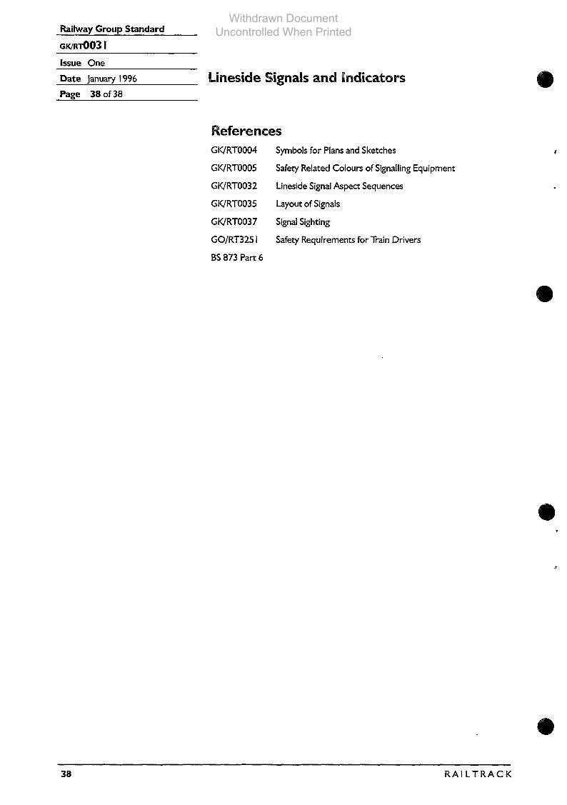
Railwav Groun Standard
Issue One
Date January 1996 LinesidePage 38 of 38
Signals am! indicators
GK/RTOO04
GWRTOO05
GWRTO032
GWRTO035
GK/RToo37
GO/RT3251
BS873 Part 6
Symbols for Plans and Sketches
Safety Related Colours of Signaling Equipment
Lineside Signal Aspect Sequences
Layout of Signals
Signal Sighting
Safety Requirements for Tmin Drivers
@.
J
38 RAIL TRACK
Withdrawn Document Uncontrolled When Printed
Recommended