Product Overview The optimum components
for every application

2
Product Overview
Steam Traps
Type SBOGravity circulation checks are used to prevent gravity circulation in heating and hot-water installations. Depending on the type, they are fitted by union nut to the cir-culation pump or with a threaded connec-tion at the pump outlet. The SBO types are available from DN 3/4 to DN 1 1/4.
Type RK 41Made of special brass (DN 15–100) or grey cast iron (DN 125–200) and with metal-to-metal seating, the non-return valve RK 41 is suitable for liquids, gases and vapours, and for use in heating installations. Soft seats available, PN 6–16, DN 15–200, short overall length to DIN EN 558-1, series 49.
Type RK 86This non-return valve distinguishes itself for standard ap pli cations in piping systems as well as for use with corrosive media and low temperatures. Soft seats available, PN 40/Class 300, DN 15–200, short overall length to DIN EN 558-1, series 49.
Type CBThe swing check valve CB 26 is a cost-efficient unit for applications involving liquids, gases and vapours. This range can be supplied in extremely short overall lengths for DN 50–300 and PN 40.
Type BBThe dual-plate check valves BB, DN 50–1000, short overall length to DIN EN 558-1, series 16, are characterized by low pressure losses and high reliability. Also suitable for gaseous media. Special versions are available with plate dampers and various linings.
BK RangeSteam traps with bimetallic regulator up to PN 630/Class 2500. BK steam traps are suited to the toughest operating con-ditions. The bimetallic regulator makes this steam trap particularly resistant to waterhammer and frost.
MK RangeSteam traps with membrane regulator up to PN 40/Class 300. The GESTRA thermostatic capsule exhibits very high control precision in discharging the con-densate. This range is suitable for both small and large condensate flowrates.
UNA RangeSteam traps with ball float up to PN 160/Class 900. Especially suitable for con-densate discharge without banking-up, for extreme and sudden fluctuations of pressure and condensate flowrate.
UNA 25 PK/PS RangePump steam trap / condensate lifter PN 40. Pumping effected by means of motive steam of up to 6 or 13 bar for condensate discharge without banking-up, suitable for all operating conditions, low pressure and vacuum applications.
Trap MonitoringThe Vaposcope VK is a sight glass that provides a visual indication of flow in pipelines and monitors the discharge downstream of steam traps. The Vapo-scope can be used in horizontal or verti-cal pipework without any modification.
Non-Return-Valves
Type VK
BK 45In applications up to PN 40/Class 300. For air-venting.
MK 45–2For large con den sate flowrates, up to 32 bar. For air-venting.
UNA 1 (left) and UNA 4Adaptable forhorizontal or ver ti cal instal-lation.
UNA 25 PKAutomatic activation of motive steam.

3www.gestra.com
Continuous and Intermittent Blowdown Valves
Type MPAFor automatic, program-controlled inter-mittent blowdown of steam boilers and waste-heat boilers. Especially suited for boilers operating without constant super-vision (TRD 604). DN 20–50, PN 40–250.
Type BAEContinuous blowdown valves with adjust-able stage nozzle , sampling valve and electric actuator for automatically con-trolled continuous blowdown. Especially suited for boilers operating without con-tinuous supervision (TRD 604). DN 15–40, PN 40–320.
Type CWOperating without auxiliary energy, the cooling water control valves type CW, PN 16, DN 25–100, are proportional con-trollers which regulate the cooling water flowrate of the users or plant components individually as a function of the cooling-water return temperature.
Type BWReturn-temperature control valves are proportional controllers operating without auxiliary energy. PN 40/25, DN 15/20/25/40, with external setting device as optional extra.BW 31 for hot waterBW 31A for hot oil
Cooling Water Control Valves
SBO 21
RK 41
RK 86
RK 86
BB
MPA 46
BAE 46
CW 41
BW 31
CW 44
4
Product Overview
Background:
Energy RecoveryEnergy Recovery after Continuous Blowdown
After continuous blowdown, irrespective of whether auto-matically controlled or manually set, it is easily possible to utilize the dissipated heat. For example, in a GESTRA blow-down flash vessel, the energy generated by the continuous blowdown in the boiler blowdown is recuperated to a large degree by flashing. In a residual blowdown cooler located downstream, the heat remaining in the flash vessel can also be used to preheat the feedwater. Our experienced special-ists in industrial systems engineering are available to you for individual advice. In Germany, the heat recovery plants made by GESTRA are eligible for an investment subsidy; according to the Income Tax Law and the Investment Subsidy Law, the grant amounts to 7.5 %.
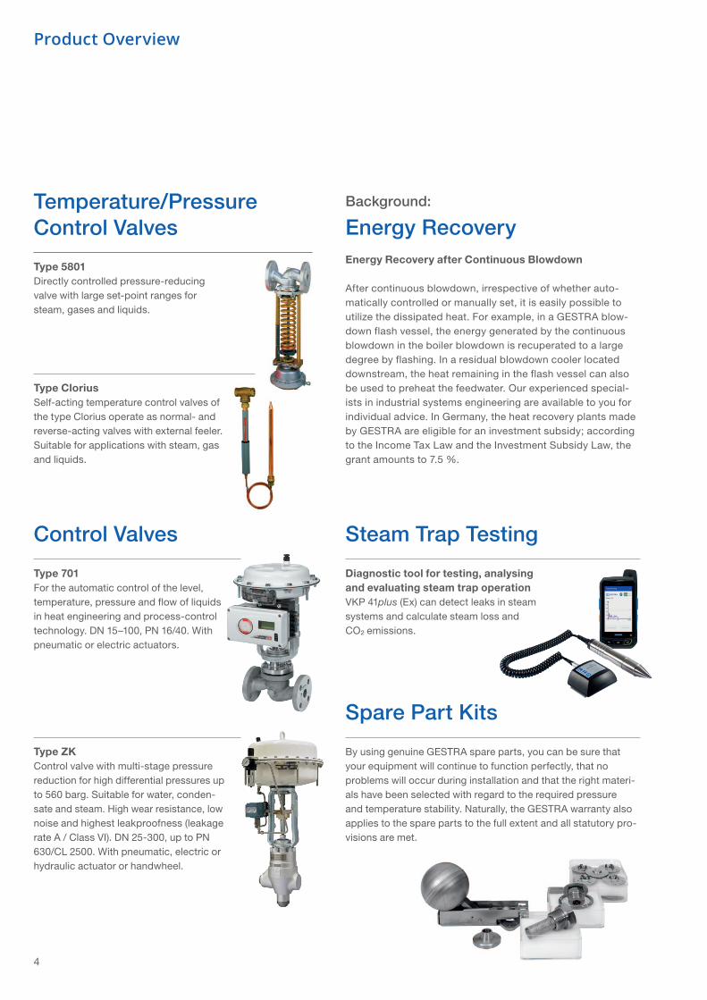
Temperature/Pressure Control Valves
Control Valves Steam Trap Testing
Spare Part Kits
Type 5801Directly controlled pressure-reducing valve with large set-point ranges for steam, gases and liquids.
Type 701For the automatic control of the level, temperature, pressure and flow of liquids in heat engineering and process-control technology. DN 15–100, PN 16/40. With pneumatic or electric actuators.
Diagnostic tool for testing, analysing and evaluating steam trap operationVKP 41plus (Ex) can detect leaks in steam systems and calculate steam loss and CO² emissions.
Type ZKControl valve with multi-stage pressure reduction for high differential pressures up to 560 barg. Suitable for water, conden-sate and steam. High wear resistance, low noise and highest leakproofness (leakage rate A / Class VI). DN 25-300, up to PN 630/CL 2500. With pneumatic, electric or hydraulic actuator or handwheel.
By using genuine GESTRA spare parts, you can be sure that your equipment will continue to function perfectly, that no problems will occur during installation and that the right materi-als have been selected with regard to the required pressure and temperature stability. Naturally, the GESTRA warranty also applies to the spare parts to the full extent and all statutory pro-visions are met.
Type CloriusSelf-acting temperature control valves of the type Clorius operate as normal- and reverse-acting valves with external feeler. Suitable for applications with steam, gas and liquids.

Feedwater tank with deaerator
Live steam
Blowdown flash vessel
Blowdown receiver
Cooling water
Pulse from intermittent blowdown valve
Steam boilerContinuous blowdown valve
Intermittent blowdown valve
From the feedwater tank
Residual blowdown cooler
Make-Up Water
20 kg/h
50 kg/h
100 kg/h
20 kg/h
50 kg/h
100 kg/h
20 kg/h
50 kg/h
100 kg/h
Hourly heat savings when the continuous blowdown flowrate is reduced by 20, 50 and 100 kg/h
Annual savings of heating oil or energy costs when the continuous blowdown flowrate is reduced by 20, 50 and 100 kg/h (taking 250 days with 24 hours = 6,000 hours) *)
Equipment investment on basis of WÜ100; units with TÜV and EU type approval (with Reactomat) not incl. installation
Equipment amortization when the top blowdown quantity is reduced by 20, 50 and 100 kg/h
Boiler pressure bar 8 16 32
W 4,126 4,844 5,231
kJ/h 14,852.8 17,436.8 18,832
W 10,314 12,109 13,078
kJ/h 37,132 43,592 47,080
W 20,629 24,218 26,156
kJ/h 74,264 87,184 94,160
kg 2,624.6 3,108.5 3,369.7
€ 787.40 932.50 1,010.90
kg 6,796.1 8,005.7 8,658.8
€ 2,038.80 2,401.70 2,597.60
kg 13,748.6 16,167.7 17,473.9
€ 4,124.60 4,850.30 5,242.20
approx. € 3,634 3,634 3,634
Months 55 47 43
Months 21 18 17
Months 10.6 9 8.3
5www.gestra.com
Schematic diagram of a blowdown flash installation with blowdown receiver
*) Calorific value of fuel 37,700 KJ/kg; efficiency 85 %; feedwater temperature 10 °C
40302010
-10-20-30-40
0
100
°F°C
8060
2032
0-20-40
40
1
15
4
5
5
69
7 8
9
12
2
3
3
12 1311
26
2425
20
20
22
23
14
18
19
19 1910
19
19
18
19
16
17
13
15
6
Product Overview
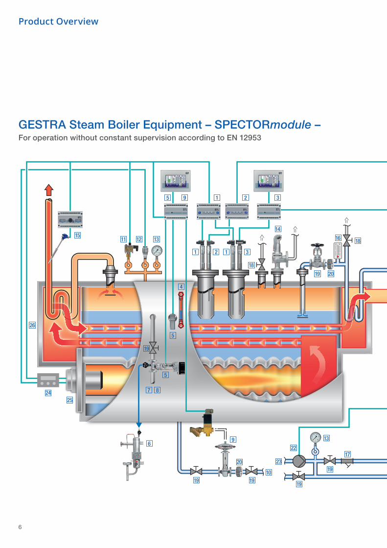
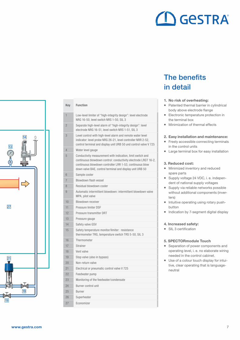
GESTRA Steam Boiler Equipment – SPECTORmodule –For operation without constant supervision according to EN 12953
40302010
-10-20-30-40
0
100
°F°C
8060
2032
0-20-40
40
21
27
14
19
13
19
Key Function
1 Low-level limiter of “high-integrity design”: level electrode NRG 16-50, level switch NRS 1-50, SIL 3 2 Separate high-level alarm of “high-integrity design”: level electrode NRG 16-51, level switch NRS 1-51, SIL 3 3 Level control with high-level alarm and remote water level indicator: level probe NRG 26-21, level controller NRR 2-52, control terminal and display unit URB 50 und control valve V 725 4 Water level gauge 5 Conductivity measurement with indication, limit switch and continuous blowdown control: conductivity electrode LRGT 16-2, continuous blowdown controller LRR 1-53, continuous blow down valve BAE, control terminal and display unit URB 50
6 Sample cooler
7 Blowdown flash vessel
8 Residual blowdown cooler
9 Automatic intermittent blowdown: intermittent blowdown valve MPA, pilot valve
10 Blowdown receiver
11 Pressure limiter DSF
12 Pressure transmitter DRT
13 Pressure gauge
14 Safety valve GSV
15 Safety temperature monitor/limiter: resistance thermometer TRG, temperature switch TRS 5-50, SIL 3
16 Thermometer
17 Strainer
18 Vent valve
19 Stop valve (also in bypass)
20 Non-return valve
21 Electrical or pneumatic control valve V 725
22 Feedwater pump
23 Monitoring of the feedwater/condensate
24 Burner control unit
25 Burner
26 Superheater
27 Economizer
7www.gestra.com
The benefitsin detail
1. No risk of overheating: Patented thermal barrier in cylindrical
body above electrode flange Electronic temperature protection in
the terminal box Minimization of thermal effects
2. Easy installation and maintenance: Freely accessible connecting terminals
in the control units Large terminal box for easy installation
3. Reduced cost: Minimized inventory and reduced
spare parts Supply voltage 24 VDC, i. e. indepen-
dent of national supply voltages Supply via reliable networks possible
without additional components (inver-ters)
Intuitive operating using rotary push-button
Indication by 7-segment digital display
4. Increased safety: SIL 3 certification
5. SPECTORmodule Touch Separation of power components and
operating level, i. e. no elaborate wiring needed in the control cabinet.
Use of a colour touch display for intui-tive, clear operating that is language-neutral

GESTRA AGMünchener Str. 77 · 28215 Bremen · Germany Tel. +49 421 3503-0 [email protected]. Box 10 54 60 · 28054 Bremen · Germany Fax +49 421 3503-393 www.gestra.com
810815-08/06-2018gw (804217-09) · © 2018 · GESTRA AG · Bremen · Printed in Germany · Subject to technical modifications
Recommended