Geothermal Tunnel Linings
Principles of Geothermal Tunnel Linings
Duncan Nicholson - Director, Ove Arup and Partners Limited
11.00 – 11.30hrs 18 October 2012
Contents
� Background – Ground source heat energy
� Concept - Thermal tunnels� Pipes in segments and connenctions� Cold tunnels and hot tunnels
� Design development process� Linking to surface
2
� Linking to surface� Thermal / ventilation design� Fire
� Building market for tunnel heat
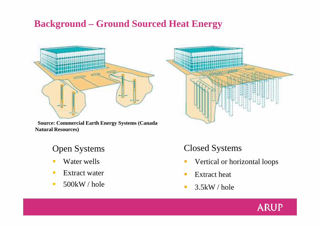
Background – Ground Sourced Heat Energy
Open Systems� Water wells
� Extract water
� 500kW / hole
Closed Systems
� Vertical or horizontal loops
� Extract heat
� 3.5kW / hole
Source: Commercial Earth Energy Systems (Canada Natural Resources)
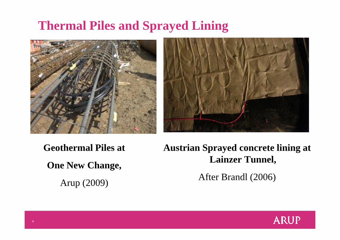
Thermal Piles and Sprayed Lining
4
Geothermal Piles at
One New Change,
Arup (2009)
Austrian Sprayed concrete lining at Lainzer Tunnel,
After Brandl (2006)
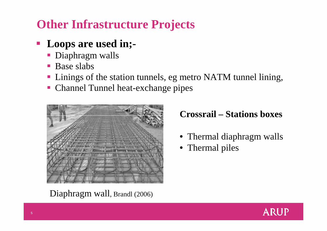
Other Infrastructure Projects
� Loops are used in;-� Diaphragm walls� Base slabs � Linings of the station tunnels, eg metro NATMtunnel lining,� Channel Tunnel heat-exchange pipes
Crossrail – Stations boxes
5
Diaphragm wall, Brandl (2006)
Crossrail – Stations boxes
• Thermal diaphragm walls • Thermal piles
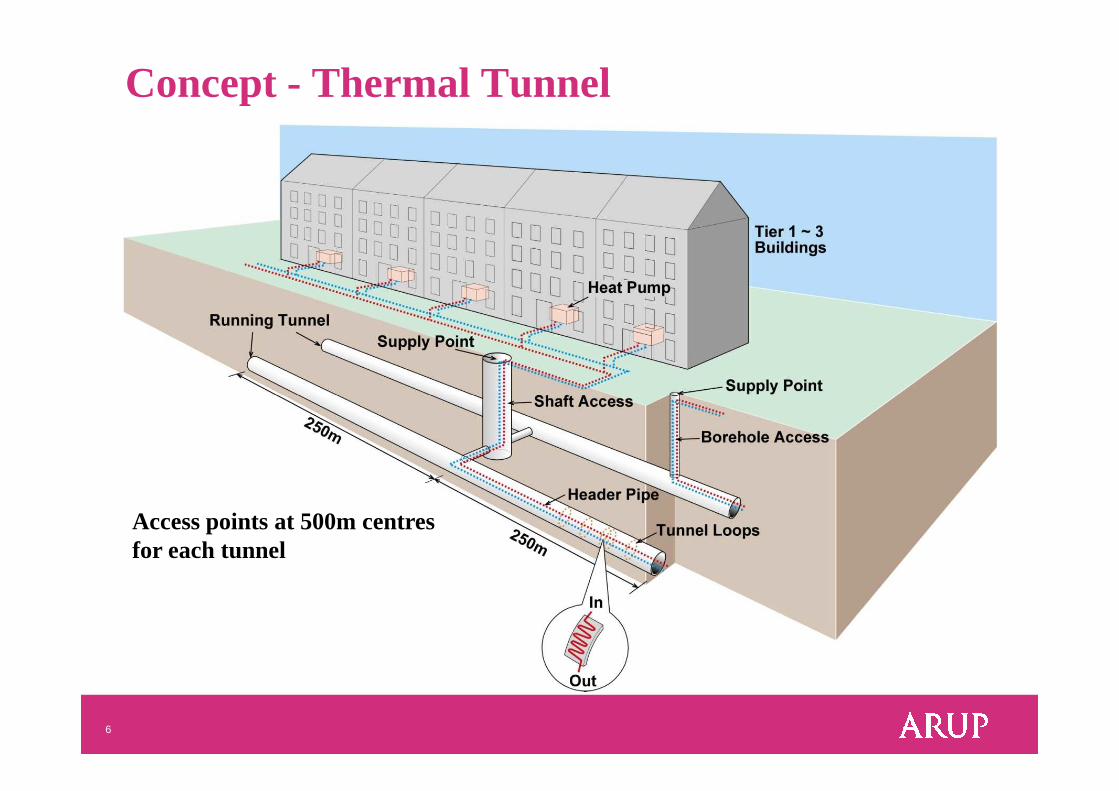
Concept - Thermal Tunnel
6
Access points at 500m centres for each tunnel
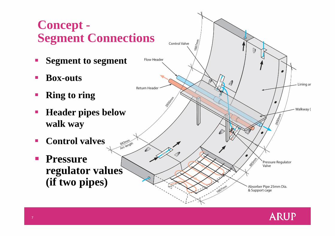
Concept -Segment Connections
� Segment to segment
� Box-outs
� Ring to ring
� Header pipes below
7
walk way
� Control valves
� Pressure regulator values (if two pipes)
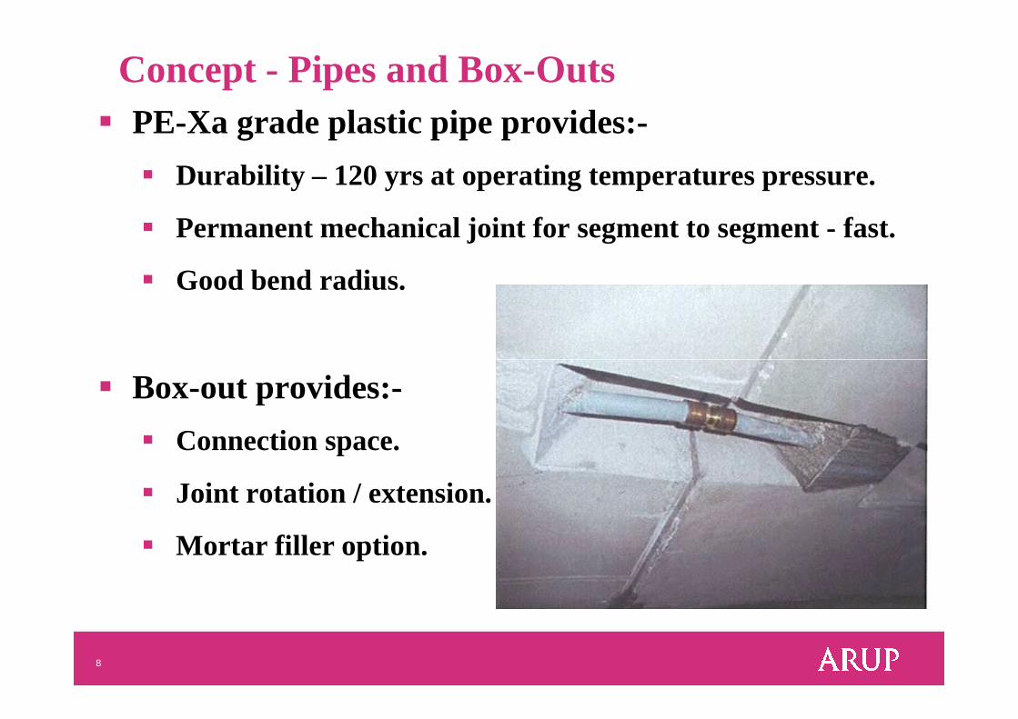
Concept - Pipes and Box-Outs � PE-Xa grade plastic pipe provides:-
� Durability – 120 yrs at operating temperatures pressure.
� Permanent mechanical joint for segment to segment - fast.
� Good bend radius.
8
� Box-out provides:-
� Connection space.
� Joint rotation / extension.
� Mortar filler option.
Flow
Return
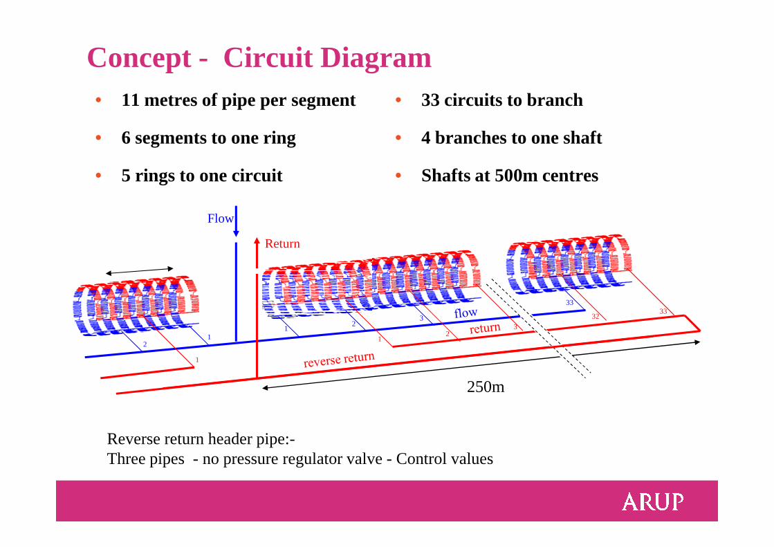
Concept - Circuit Diagram• 11 metres of pipe per segment
• 6 segments to one ring
• 5 rings to one circuit
• 33 circuits to branch
• 4 branches to one shaft
• Shafts at 500m centres
12
3
33
12
3
3332
1
1
2
250m
Reverse return header pipe:-Three pipes - no pressure regulator valve - Control values
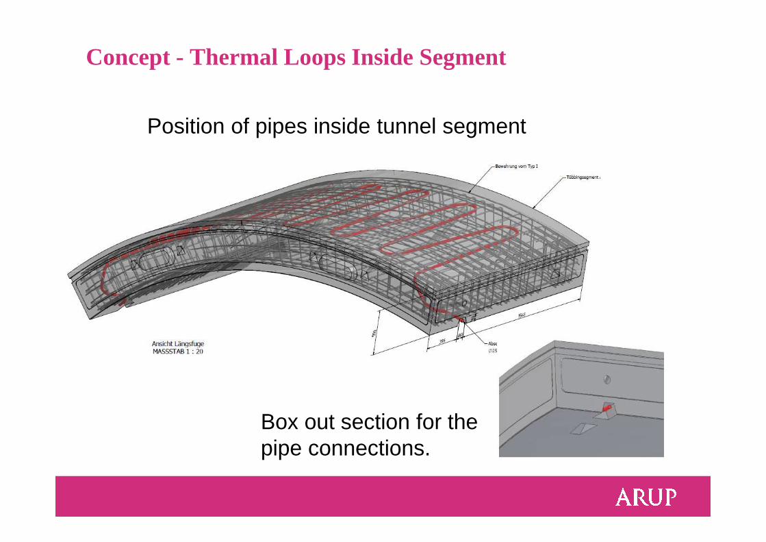
Position of pipes inside tunnel segment
Concept - Thermal Loops Inside Segment
Box out section for the pipe connections.
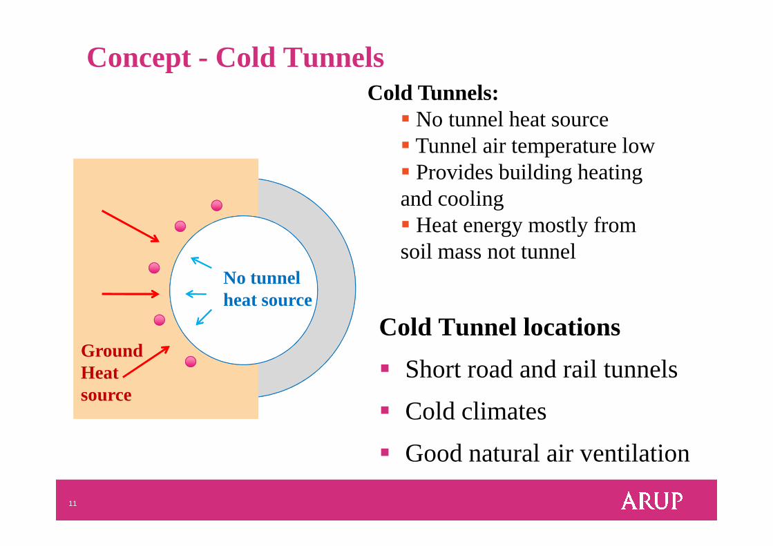
Concept - Cold TunnelsCold Tunnels:
� No tunnel heat source� Tunnel air temperature low� Provides building heating and cooling � Heat energy mostly from soil mass not tunnel
No tunnel
11
Cold Tunnel locations
� Short road and rail tunnels
� Cold climates
� Good natural air ventilation
No tunnelheat source
Ground Heat source
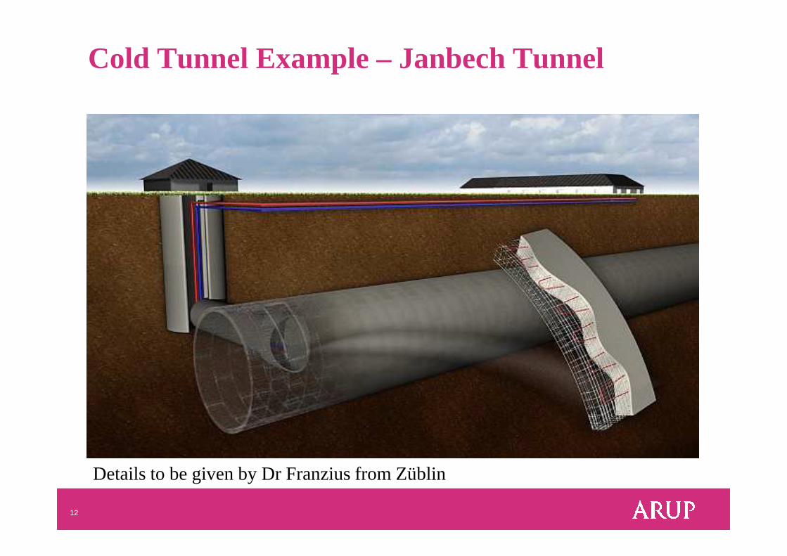
Cold Tunnel Example – JanbechTunnel
12
Details to be given by Dr Franzius from Züblin
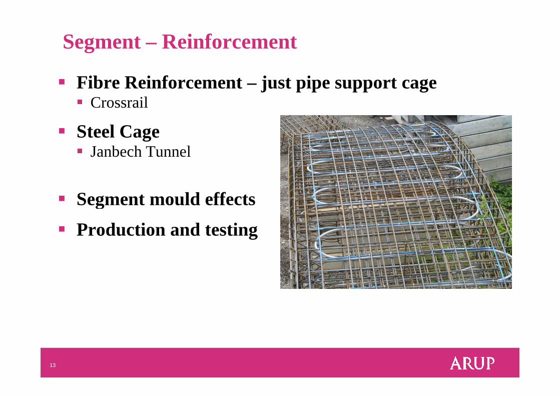
Segment – Reinforcement
� Fibre Reinforcement – just pipe support cage � Crossrail
� Steel Cage � Janbech Tunnel
� Segment mould effects
13
� Segment mould effects
� Production and testing
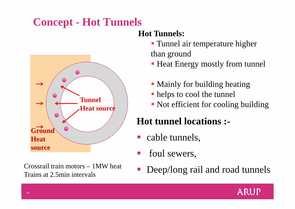
Concept - Hot TunnelsHot Tunnels:
� Tunnel air temperature higher than ground� Heat Energy mostly from tunnel
� Mainly for building heating� helps to cool the tunnel� Not efficient for cooling building
Tunnel Heat source
14
Hot tunnel locations :-
� cable tunnels,
� foul sewers,
� Deep/long rail and road tunnels
� Not efficient for cooling building Heat source
Ground Heat source
Crossrail train motors – 1MW heatTrains at 2.5min intervals
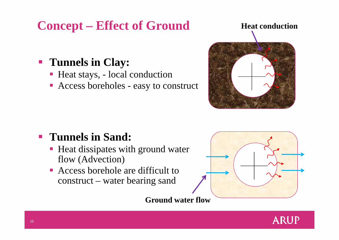
Concept – Effect of Ground
� Tunnels in Clay: � Heat stays, - local conduction � Access boreholes - easy to construct
Heat conduction
15
� Tunnels in Sand: � Heat dissipates with ground water
flow (Advection)� Access borehole are difficult to
construct – water bearing sand
Ground water flow
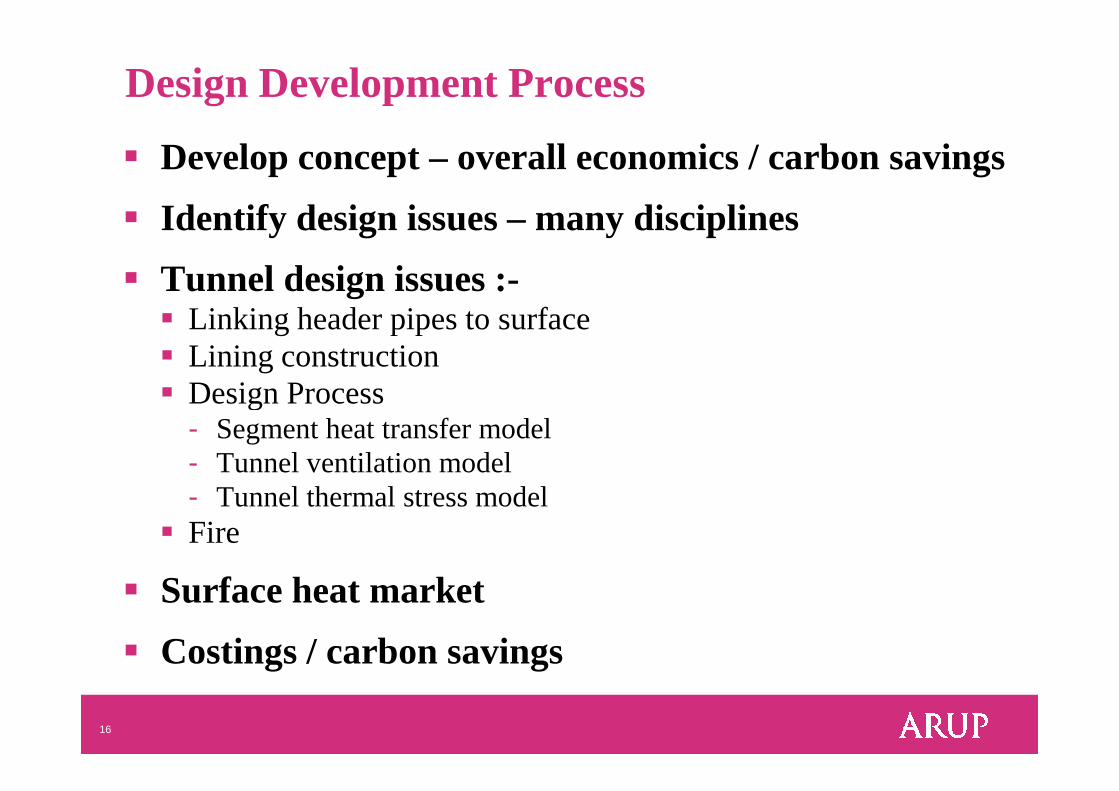
Design Development Process
� Develop concept – overall economics / carbon savings
� Identify design issues – many disciplines
� Tunnel design issues :-� Linking header pipes to surface � Lining construction� Design Process
16
� Design Process- Segment heat transfer model - Tunnel ventilation model- Tunnel thermal stress model
� Fire
� Surface heat market
� Costings / carbon savings
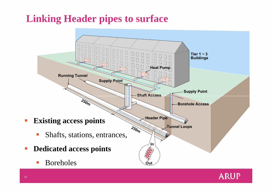
Linking Header pipes to surface
17
� Existing access points
� Shafts, stations, entrances,
� Dedicated access points
� Boreholes
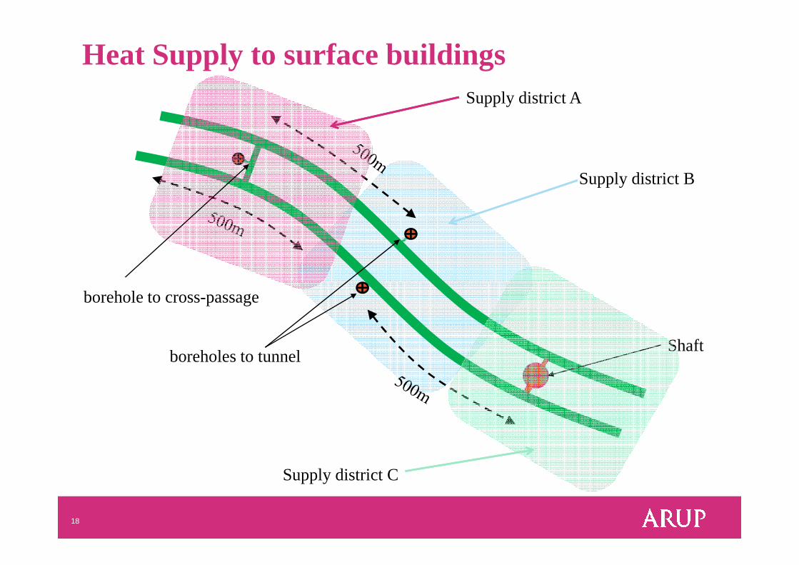
Supply district A
Supply district B
Heat Supply to surface buildings
18
Shaft
Supply district C
borehole to cross-passage
boreholes to tunnel
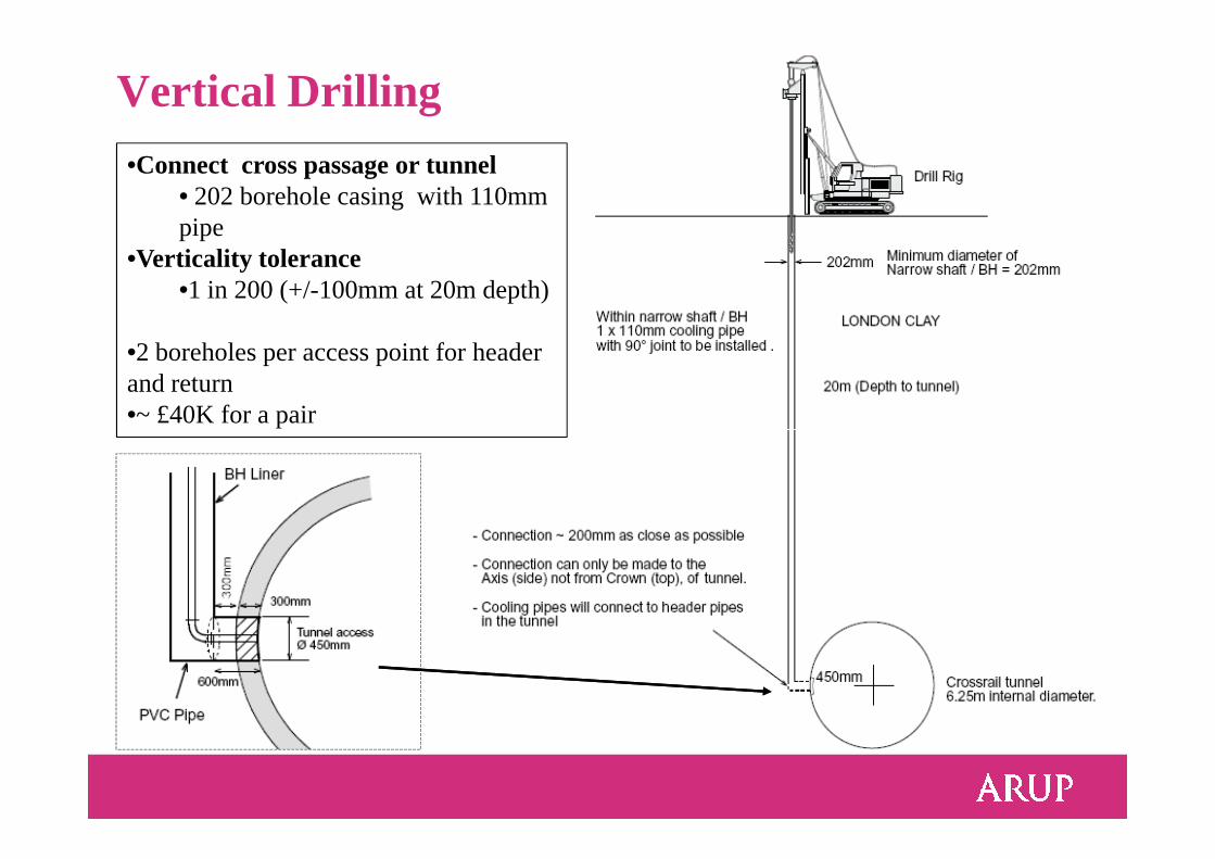
Vertical Drilling
•Connect cross passage or tunnel • 202 borehole casing with 110mm pipe
•Verticality tolerance •1 in 200 (+/-100mm at 20m depth)
•2 boreholes per access point for header and return•~ £40K for a pair
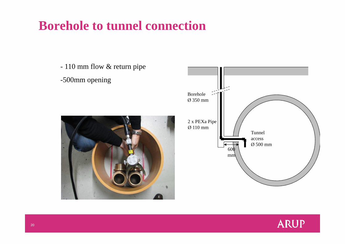
- 110 mm flow & return pipe
-500mm opening
BoreholeØ 350 mm
2 x PEXa Pipe
Borehole to tunnel connection
20
Tunnel accessØ 500 mm
600 mm
2 x PEXa PipeØ 110 mm
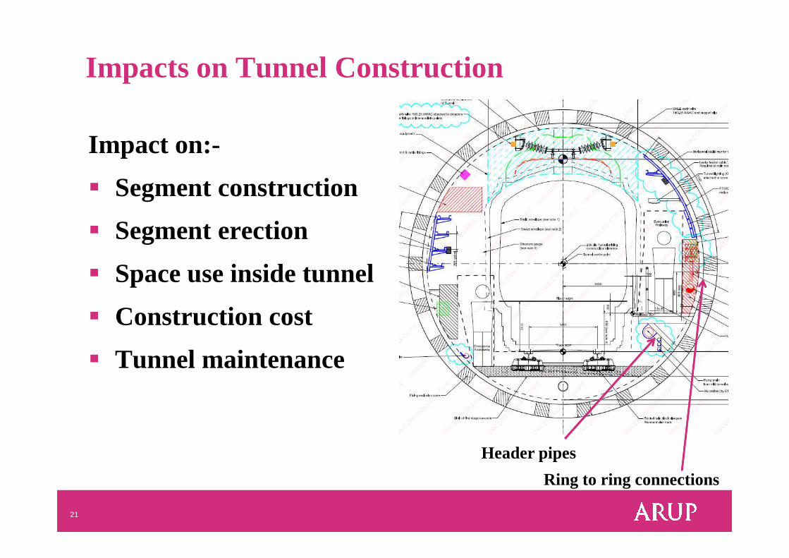
Impacts on Tunnel Construction
Impact on:-
� Segment construction
� Segment erection
� Space use inside tunnel
21
� Space use inside tunnel
� Construction cost
� Tunnel maintenance
Header pipes
Ring to ring connections
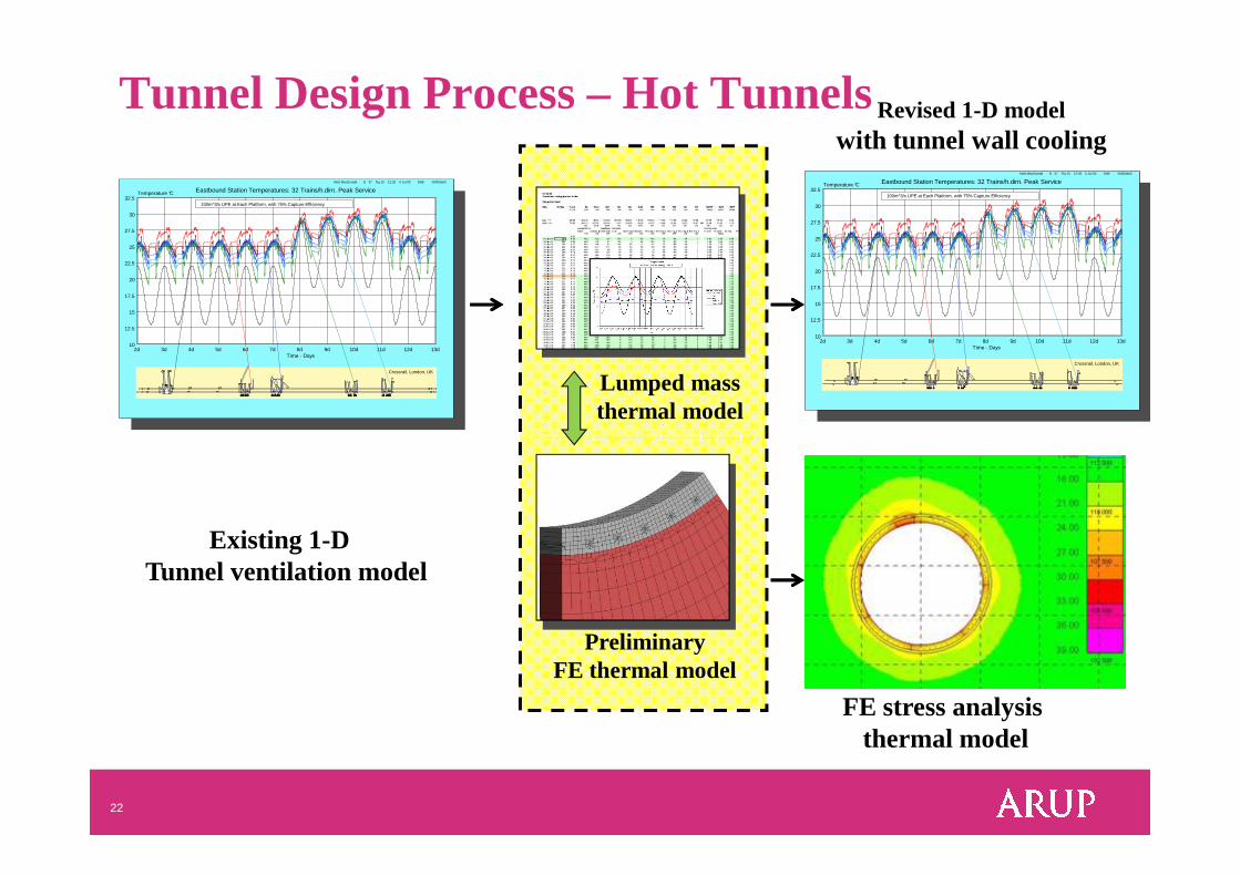
Tunnel Design Process – Hot Tunnels
Mott MacDonald B 37 Fig 15 12:26 5 Jul 00 DAB 00000a00
10
12.5
15
17.5
20
22.5
25
27.5
30
32.5Temperature °C
2d 3d 4d 5d 6d 7d 8d 9d 10d 11d 12d 13d Time - Days
Eastbound Station Temperatures: 32 Trains/h.dirn. Peak Service
100m^3/s UPE at Each Platform, with 75% Capture Efficiency
Crossrail, London, UK
Lumped massthermal model
Revised 1-D modelwith tunnel wall cooling
Mott MacDonald B 37 Fig 15 12:26 5 Jul 00 DAB 00000a00
10
12.5
15
17.5
20
22.5
25
27.5
30
32.5Temperature °C
2d 3d 4d 5d 6d 7d 8d 9d 10d 11d 12d 13d Time - Days
Eastbound Station Temperatures: 32 Trains/h.dirn. Peak Service
100m^3/s UPE at Each Platform, with 75% Capture Efficiency
Crossrail, London, UK
22
Existing 1-D Tunnel ventilation model
FE stress analysis thermal model
PreliminaryFE thermal model
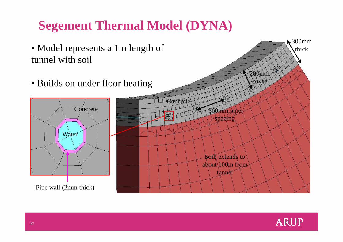
Segement Thermal Model (DYNA)
360mm pipe spacing
200mmcover
• Model represents a 1m length of tunnel with soil
• Builds on under floor heating
Concrete
300mm thick
Concrete
23
Pipe wall (2mm thick)
spacing
Soil, extends to about 100m from
tunnel
Water
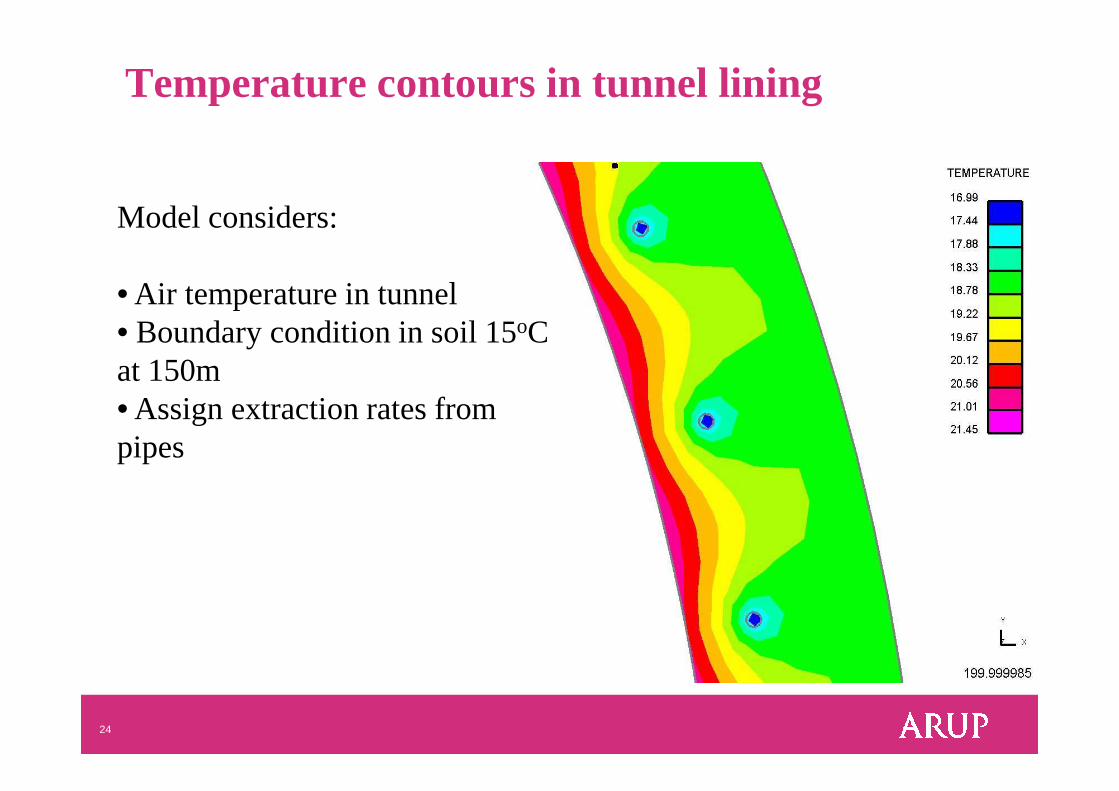
Temperature contours in tunnel lining
Model considers:
• Air temperature in tunnel• Boundary condition in soil 15oC at 150m• Assign extraction rates from
24
• Assign extraction rates from pipes
20
25
30
35P
ipe
Ave
rage
Tem
pera
ture
(D
eg C
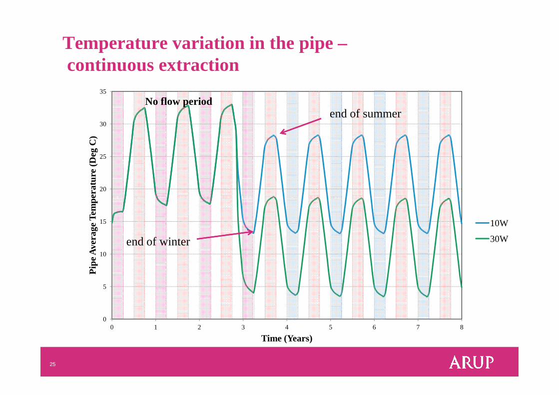
)No flow period
Temperature variation in the pipe –continuous extraction
end of summer
25
0
5
10
15
0 1 2 3 4 5 6 7 8
Pip
e A
vera
ge T
empe
ratu
re (
Deg
C)
Time (Years)
10W
30Wend of winter
10
15
20
25
30
35
Flu
id te
mpe
ratu
re (
degr
ees
C)
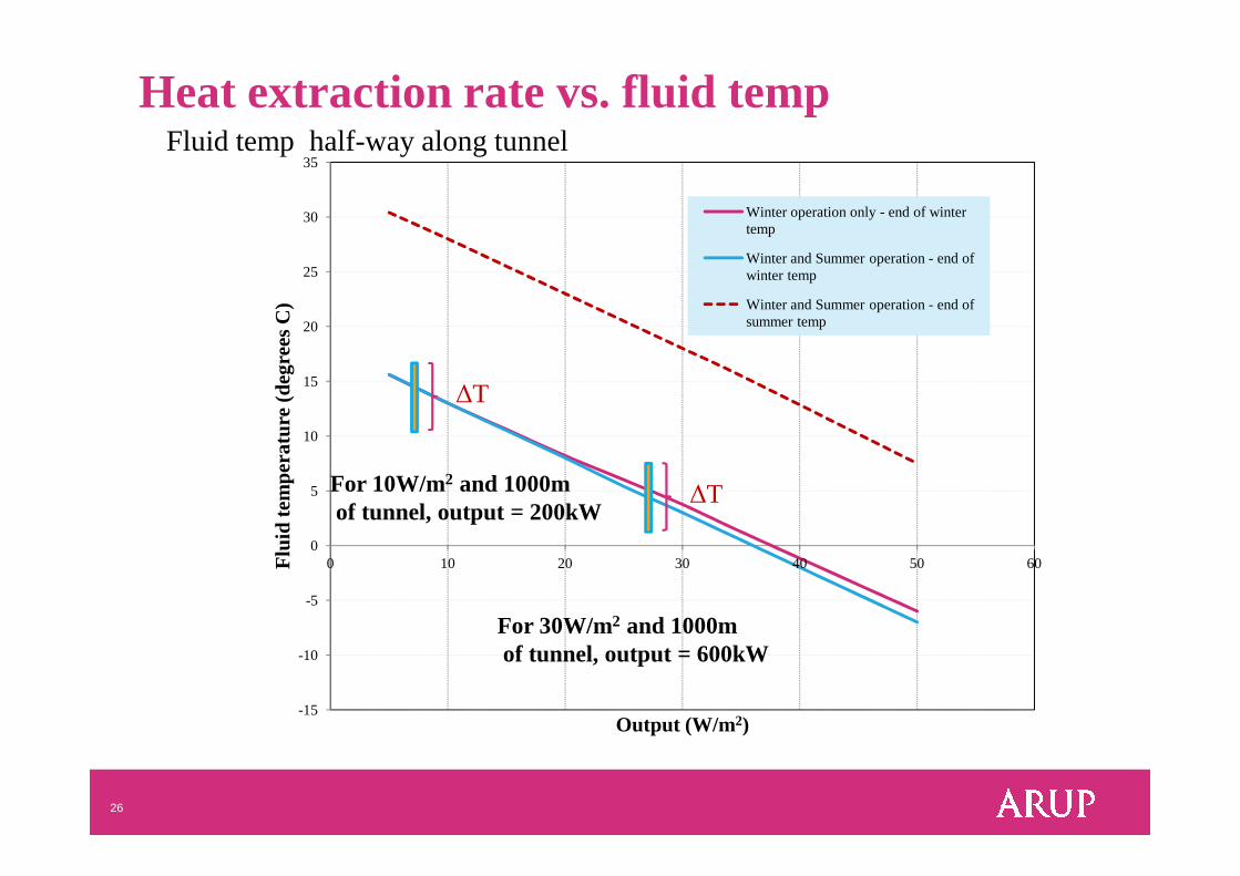
Fluid temp half-way along tunnel
Winter operation only - end of winter temp
Winter and Summer operation - end of winter temp
Winter and Summer operation - end of summer temp
Heat extraction rate vs. fluid temp
∆T
26
-15
-10
-5
0
5
10
0 10 20 30 40 50 60Flu
id te
mpe
ratu
re
Output (W/m 2)
For 10W/m2 and 1000mof tunnel, output = 200kW
For 30W/m2 and 1000mof tunnel, output = 600kW
∆T
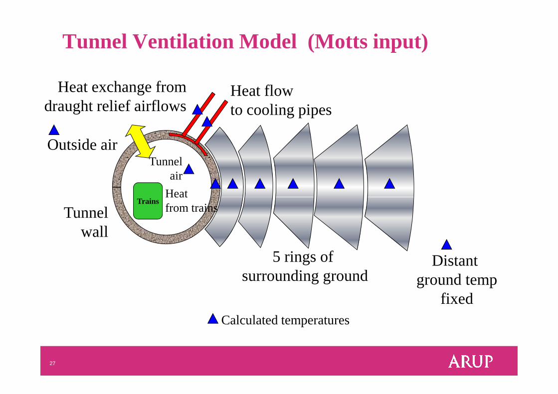
Tunnel Ventilation Model (Motts input)
Heat exchange fromdraught relief airflows
TrainsHeat
Heat flowto cooling pipes
Outside airTunnel
air
27
5 rings ofsurrounding ground
Distantground temp
fixed
Trains
Tunnelwall
Heatfrom trains
Calculated temperatures
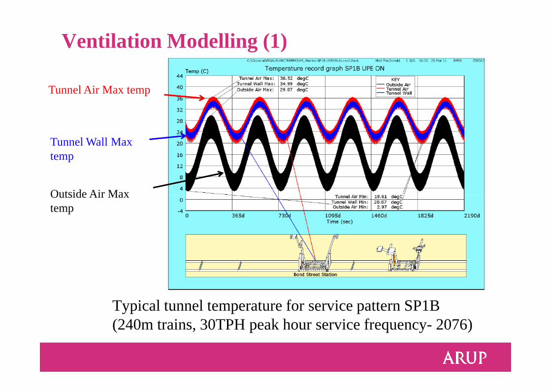
Ventilation Modelling (1)
Tunnel Air Max temp
Tunnel Wall Max temp
Outside Air Max
Typical tunnel temperature for service pattern SP1B (240m trains, 30TPH peak hour service frequency- 2076)
Outside Air Max temp
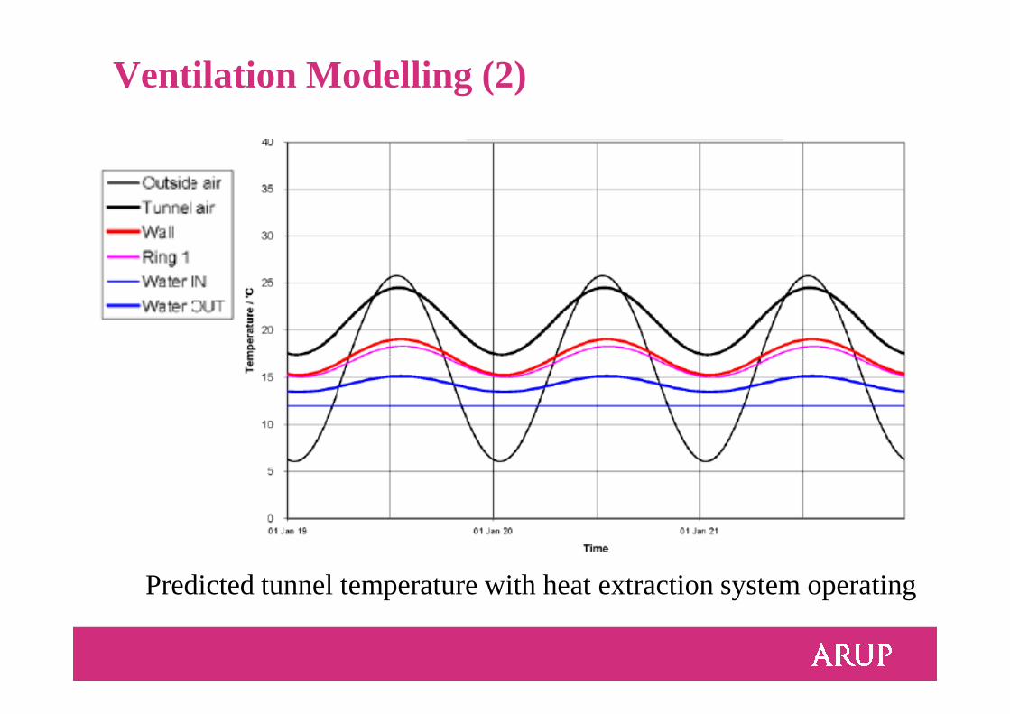
Ventilation Modelling (2)
Predicted tunnel temperature with heat extraction system operating
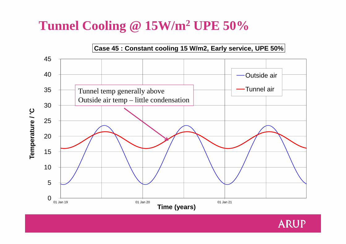
Tunnel Cooling @ 15W/m2 UPE 50%
25
30
35
40
45
Tem
pera
ture
/ 'C
Outside air
Tunnel air
Case 45 : Constant cooling 15 W/m2, Early service, UPE 50%
Tunnel temp generally above Outside air temp – little condensation
0
5
10
15
20
25
01 Jan 19 01 Jan 20 01 Jan 21
Tem
pera
ture
/ 'C
Time (years)
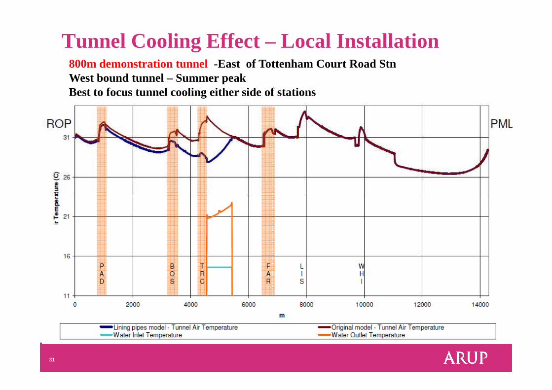
Tunnel Cooling Effect – Local Installation800m demonstration tunnel -East of Tottenham Court Road Stn West bound tunnel – Summer peak Best to focus tunnel cooling either side of stations
31
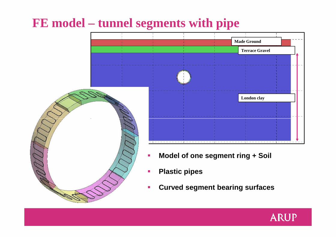
FE model – tunnel segments with pipe
London clay
Terrace Gravel
Made Ground
� Model of one segment ring + Soil
� Plastic pipes
� Curved segment bearing surfaces
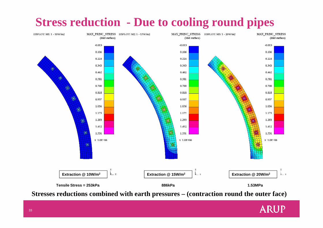
Stress reduction - Due to cooling round pipes
33
Extraction @ 10W/m 2 Extraction @ 15W/m 2 Extraction @ 20W/m 2
Tensile Stress = 253kPa 886kPa 1.53MPa
Stresses reductions combined with earth pressures – (contraction round the outer face)
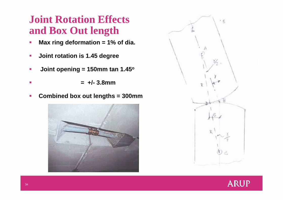
Joint Rotation Effects and Box Out length� Max ring deformation = 1% of dia.
� Joint rotation is 1.45 degree
� Joint opening = 150mm tan 1.45 o
� = +/- 3.8mm
� Combined box out lengths = 300mm
34
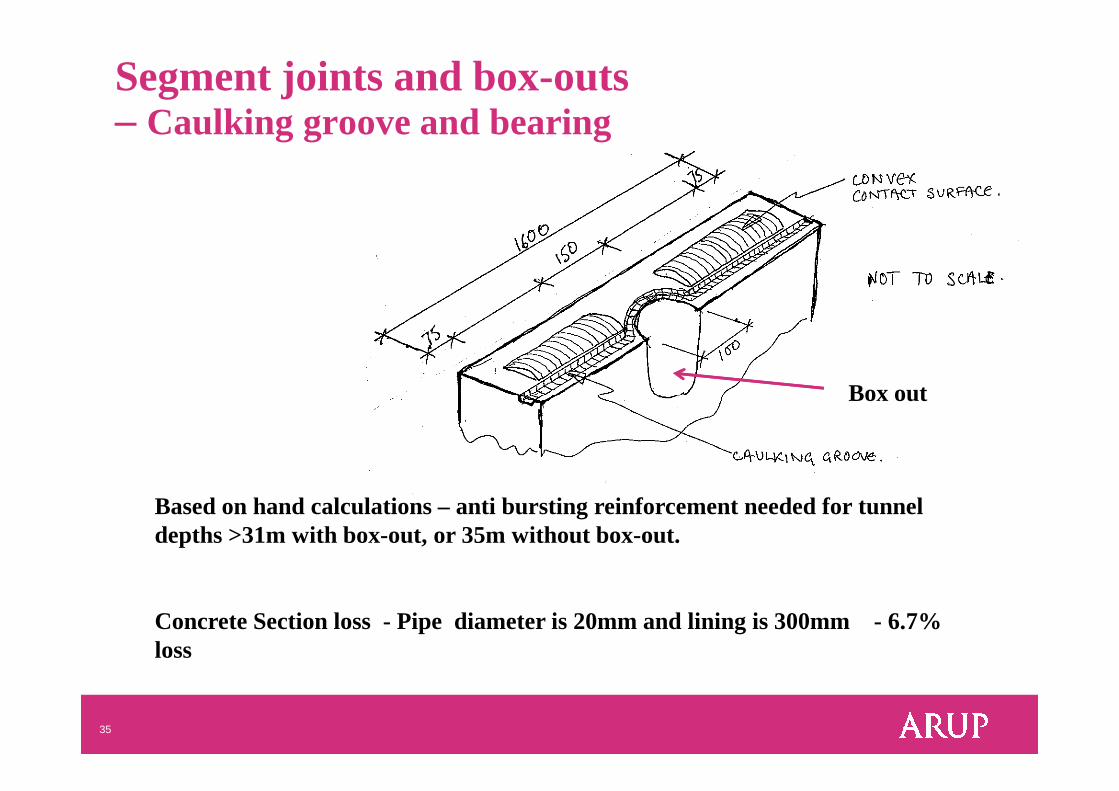
Box out
Segment joints and box-outs – Caulking groove and bearing
35
Based on hand calculations – anti bursting reinforcement needed for tunnel depths >31m with box-out, or 35m without box-out.
Concrete Section loss - Pipe diameter is 20mm and lining is 300mm - 6.7% loss
Box out
Fire
� Fire load - EUREKA fire curve
� Spalling margin of the segment
� Stakeholders: To consider PE pipes� LU 1-085 Fire Safety of Materials
36
� LU 1-085 Fire Safety of Materials
� PEX-a Pipes: Durability 100 years at 20oC and 15 bar (according to DIN 16892/16893, EN ISO 15875) incl. FoS 1.25
� Check ventilation capacity to remove smoke
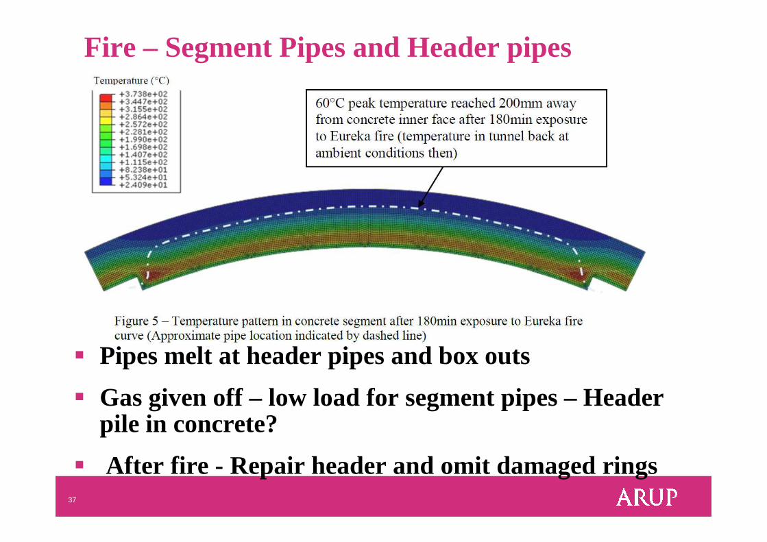
Fire – Segment Pipes and Header pipes
37
� Pipes melt at header pipes and box outs
� Gas given off – low load for segment pipes – Header pile in concrete?
� After fire - Repair header and omit damaged rings
Market for Tunnel Geothermal
� Low grade energy source – use locally
� Residential buildings – heating demand +Hot water
� Office blocks – cooling and heating demands
38
� Old buildings - refurbishment – heat + Hot water
� New buildings - renewable source requirement� Helps at Planning Stage with Part L
� Cools tubes / ground – reduces ventilation costs
Typical London Residential Building
� Typical 5 Storey – refurbished buildings� heating needs – 40-50W/m2 of floor.
� Say 16 flats /building unit � Space heating – 40kW. – seasonal
39
� Space heating – 40kW. – seasonal � Hot water – 25kW. – continuous
� Similar to 50 to 100m long tunnel section.
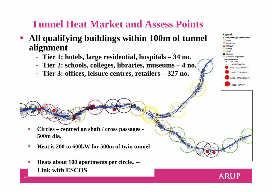
Tunnel Heat Market and Assess Points � All qualifying buildings within 100m of tunnel
alignment- Tier 1: hotels, large residential, hospitals – 34 no.- Tier 2: schools, colleges, libraries, museums – 4 no.- Tier 3: offices, leisure centres, retailers – 327 no.
40
� Circles – centred on shaft / cross passages -500m dia.
� Heat is 200 to 600kW for 500m of twin tunnel
� Heats about 100 apartments per circle. –Link with ESCOS
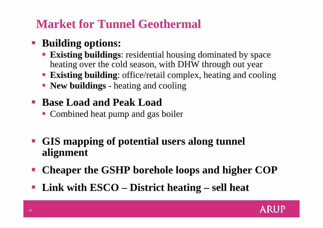
Market for Tunnel Geothermal
� Building options:� Existing buildings: residential housing dominated by space
heating over the cold season, with DHWthrough out year� Existing building: office/retail complex, heating and cooling� New buildings - heating and cooling
� Base Load and Peak Load� Combined heat pump and gas boiler
41
� Combined heat pump and gas boiler
� GIS mapping of potential users along tunnel alignment
� Cheaper the GSHP borehole loops and higher COP
� Link with ESCO – District heating – sell heat
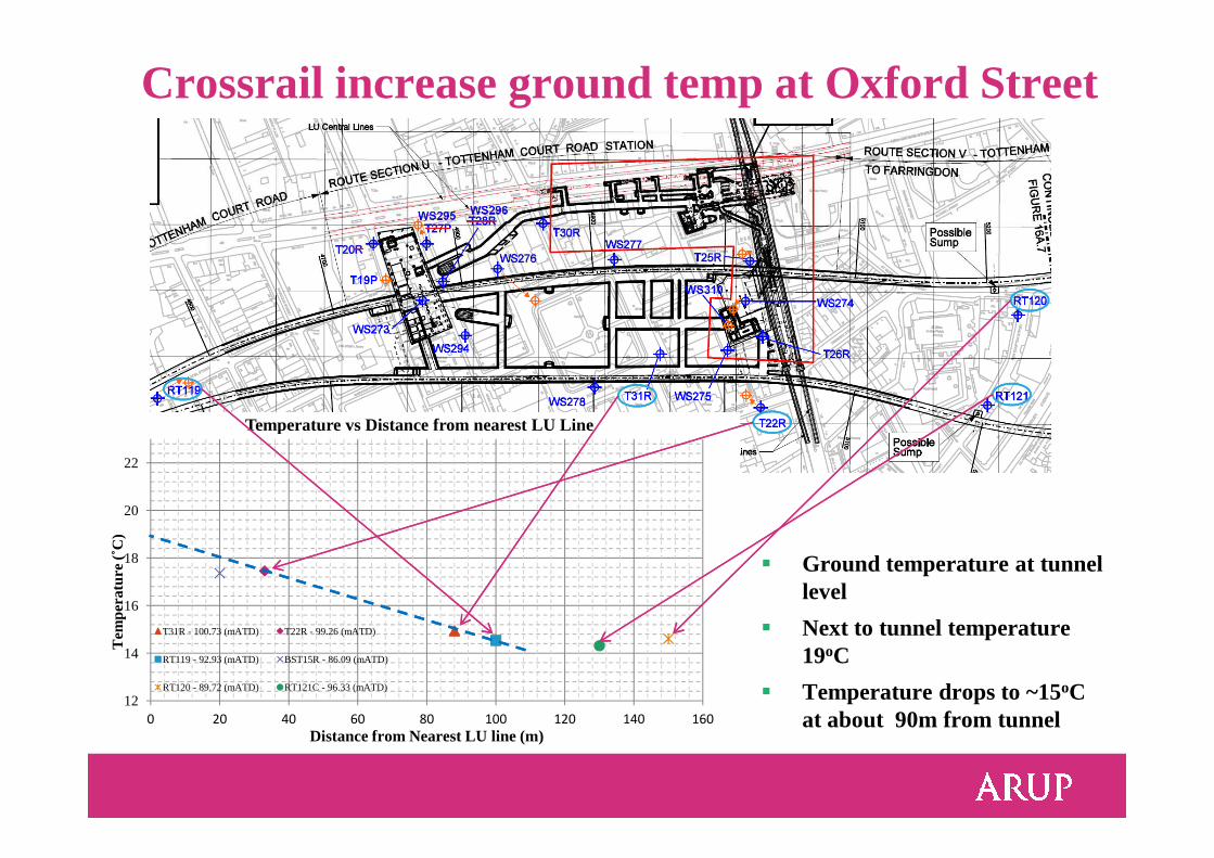
Crossrail increase ground temp at Oxford Street
Temperature vs Distance from nearest LU Line
12
14
16
18
20
22
0 20 40 60 80 100 120 140 160
Tem
pera
ture
(˚C
)
Distance from Nearest LU line (m)
Temperature vs Distance from nearest LU Line
T31R - 100.73 (mATD) T22R - 99.26 (mATD)
RT119 - 92.93 (mATD) BST15R - 86.09 (mATD)
RT120 - 89.72 (mATD) RT121C - 96.33 (mATD)
� Ground temperature at tunnel level
� Next to tunnel temperature 19oC
� Temperature drops to ~15oC at about 90m from tunnel
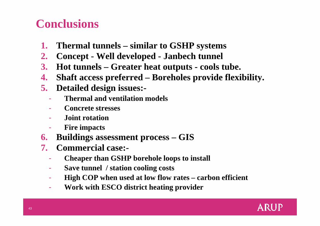
Conclusions
1. Thermal tunnels – similar to GSHP systems2. Concept - Well developed - Janbech tunnel3. Hot tunnels – Greater heat outputs - cools tube.4. Shaft access preferred – Boreholes provide flexibility.5. Detailed design issues:-
- Thermal and ventilation models- Concrete stresses
43
- Joint rotation- Fire impacts
6. Buildings assessment process – GIS 7. Commercial case:-
- Cheaper than GSHP borehole loops to install- Save tunnel / station cooling costs- High COP when used at low flow rates – carbon efficient- Work with ESCO district heating provider

Thank you for your attention
Any Questions?
44
Any Questions?
Recommended