GEOSYNTHETICS ENGINEERING: IN THEORY AND PRACTICE
Prof. J. N. Mandal
Department of civil engineering, IIT Bombay, Powai , Mumbai 400076, India. Tel.022-25767328email: [email protected]
Prof. J. N. Mandal, Department of Civil Engineering, IIT Bombay

Prof. J. N. Mandal, Department of Civil Engineering, IIT Bombay
Module - 9LECTURE - 47
Geosynthetics for ground improvement

Recap of previous lecture…..
Prof. J. N. Mandal, Department of Civil Engineering, IIT Bombay
Design chart with smear effect and well resistance
Instrumentation of embankment on soft sol with PVDs
Installation of PVD
Design example (partially covered)

Step 8: Calculated the shear strength (improved) in eachstage
.S.FxNc
strengthShear cfinalu)improved(
cu(final) = Cohesion after the improvement,Nc = Bearing capacity factor = 5.7, andF.S. = Factor of safety.
2)improved( m/t28.7
37.5x83.3strengthShear
2)improved( m/t3.9
37.5x9.4strengthShear
Improvement in shear strength after stage I,
Improvement in shear strength after stage II
Prof. J. N. Mandal, Department of Civil Engineering, IIT Bombay

2)improved( m/t83.10
37.5x7.5strengthShear
Improvement in shear strength after stage III,
Step 9: Determine the height of fill (that can be safelyplaced on soil) for the next stage by following equation.
embankment
stagepreviousin)improved(fill
strengthShearH
Hfill = Height of fill that can safely be placed over the soil,γembankment = Unit weight of embankment soil = 1.8 t/ m3
As the shear strength improved in first stage is 7.28 t/m2,7.28 41.8fillH m
Prof. J. N. Mandal, Department of Civil Engineering, IIT Bombay

Step 10: Check whether the shear strength of soil isgreater than the bearing capacity of soil (Determined instep 1) or not; if not, revise the days.
The settlement after N number of stages should alsobe greater than the settlement calculated by generalconsolidation theory in step 2.
In put Soil Properties
1 Thickness of compressible layer, H(m) 102 Maximum Height of Reinforced Earth wall, h1(m) 4.353 Live load equivalent to embankment, H1 (m) 2.74 Hence total height of embankment (m) 7.055 Density of embankment (T/cum) 1.86 Density of compressible soil (T/cum) 1.77 Initial void ratio 1.28 PI 279 Horizontal degree of consolidation (m2/day) 2.20E-02
10 Vertical degree of consolidation (m2/day)11 Initial Cohesion os soil (T/m2) 2.512 Compression Index of Soil 0.24313 Factor of safety for SBC 3
Design Go to main screen
Prof. J. N. Mandal, Department of Civil Engineering, IIT Bombay

Stage loading Calculation
Stage of Loading I II IIITime Days 30 10 5Total fill Ht. meter 3 4 5Degree of Consolidation % 0.91 0.55 0.33Initial Cohesion, C T/m2 2.5 3.834151 4.9Initial Shear Strength T/m2 4.75 7.284887 9.3Cohesion after consolidation T/m2 3.834151 4.9 5.7Shear Strength T/m2 7.284887 9.3 10.83 > 7.4 t/m2Total ht of fill can be placed meter 4.047159 5.2 6.016667Hence, Provide 4 5
Settlement mm 410 156 70
Total settlement 636 OK
Prof. J. N. Mandal, Department of Civil Engineering, IIT Bombay

Settlement calculation in stage I, S1 = (U%) x δI
)17.1(5
8.13)17.1(5log2.1110243.091.0
ppplog
e1HC91.0S 10
0
0
0
c1
S1 = 0.91 x 447.69 mm ≈ 410 mm
Settlement calculation in stage II, S2 = (U%) x δII
)8.137.05(
8.14)8.137.05(log2.1110243.055.0
ppplog
e1HC55.0S 10
0
0
0
c2
S2 = 0.55 x 284.35 mm = 156 mm
p0= H/2 x γeffective γeffective = (γsaturated - 1) = 1.7-1 = 0.7 t/ m3
Prof. J. N. Mandal, Department of Civil Engineering, IIT Bombay

Settlement calculation in stage III, S3 = (U %) x δ III
)8.148.137.05(
8.15)8.148.137.05(log2.1110243.033.0
ppplog
e1HC33.0S 10
0
0
0
c3
S3 = 0.33 x 213 mm = 70 mm
Prof. J. N. Mandal, Department of Civil Engineering, IIT Bombay

Results and Summary:Ist Stage IInd Stage IIIrd Stage
Total height of embankment (m)
3.0 4.0 5.0
Degree of consolidation (%)
91 55 33
Period (days) 30 10 5Settlement (mm) 410 156 70
Shear strength (t/m2) 7.28 9.3 10.83After IIIrd stage,
Total settlement = (410 + 156 + 70) = 636 mm > 563.49 mm (calculated in Step 2), and
Bearing capacity = 10.83 t/m2 > 7.4 t/m2 (required). So, it is O.K.
Prof. J. N. Mandal, Department of Civil Engineering, IIT Bombay

Excel Program
Prof. J. N. Mandal, Department of Civil Engineering, IIT Bombay

GEOSYNTHETIC ENCASED STONE COLUMNS
Load carrying capacity of the ground treated withgeosynthetic encased stone column may be obtained bysumming up the contribution of each of the followingcomponents under wide spread load such as tanks,embankments, pavements etc.
A] Capacity of the stone column resulting from theresistance offered by the surrounding soil against itslateral deformation i.e., bulging under axial load.
B] Capacity of the stone column resulting from the bearingsupport provided by the intervening soil.
Prof. J. N. Mandal, Department of Civil Engineering, IIT Bombay

C] Capacity of the stone column resulting from increasein resistance offered by the surrounding soil due tosurcharge over it.
D] Capacity of the stone column resulting from increasein resistance offered by the confining effect dueperipheral geosynthetics encasement.
Geosynthetics encased stone columnProf. J. N. Mandal, Department of Civil Engineering, IIT Bombay
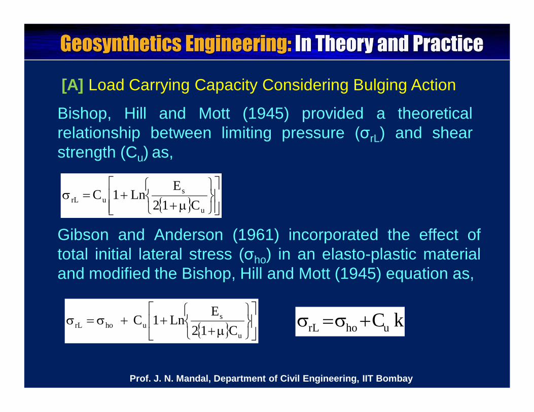
[A] Load Carrying Capacity Considering Bulging Action
Bishop, Hill and Mott (1945) provided a theoreticalrelationship between limiting pressure (σrL) and shearstrength (Cu) as,
u
surL C12
ELn1C
Gibson and Anderson (1961) incorporated the effect oftotal initial lateral stress (σho) in an elasto-plastic materialand modified the Bishop, Hill and Mott (1945) equation as,
u
su horL C12
ELn1C k CuhorL
Prof. J. N. Mandal, Department of Civil Engineering, IIT Bombay

σrL = limit pressure in a pressure meter,Es = the elastic modules of soil,
Cu = undrained shear strength of soil, and
µ = Poisson’s ratio
1C2ELn1k
u
s
Based on the field records, Hughes and withers (1974)demonstrated that the limit pressure (σrL) may beapproximated to an acceptable solution replacingrigorous analytical solution as follows.
OuhorL Uk C Uo = initial excess hydrostatic pore water pressure
Prof. J. N. Mandal, Department of Civil Engineering, IIT Bombay
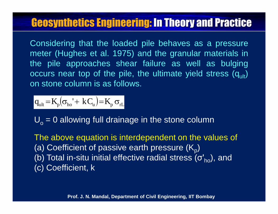
Considering that the loaded pile behaves as a pressuremeter (Hughes et al. 1975) and the granular materials inthe pile approaches shear failure as well as bulgingoccurs near top of the pile, the ultimate yield stress (qult)on stone column is as follows.
rLpuhopult KC k'Kq
Uo = 0 allowing full drainage in the stone column
The above equation is interdependent on the values of (a) Coefficient of passive earth pressure (Kp)(b) Total in-situ initial effective radial stress (σ'ho), and(c) Coefficient, k
Prof. J. N. Mandal, Department of Civil Engineering, IIT Bombay

(a) Coefficient of passive earth pressure, Kp
2/'45tanK 2p
ɸ' refers to angle of internal friction for compactedgranular fill in the stone column. It can be taken in therange 45°-55°, say 55° for rammed stone columns(Nayak, 1985)
(b) Total in-situ initial effective radial stress, σ'ho
'K' vooho
Prof. J. N. Mandal, Department of Civil Engineering, IIT Bombay

σ'vo = Effective vertical stress at depth ‘Z’ = γsub x Z
Z = 4 x Diameter of stone column (i.e. at critical length ofstone column)
Ko = Average coefficient of lateral earth pressurecorresponding to undisturbed state of soil i.e. at restcondition,
Soil type Ko RemarksGranular, Loose 0.5 to 0.6 Thus for granular materials,
an average value of Ko = 0.5 and that for soft clays
0.9 may be taken for design purpose
Granular, Dense 0.3 to 0.5Soft clay 0.9 to 1.1Hard clay 0.8 to 0.9
Prof. J. N. Mandal, Department of Civil Engineering, IIT Bombay

Total initial effective radial stress (σ'ho) can be consideredequal to 2Cu or can be obtained from limiting pressure-strainrelationship achieved form in-situ pressuremeter tests(Hughes et al., 1975).
(c) Coefficient, k
}1{C2Eln1k
u
s rIln1k
Ir = Rigidity Index (Vesic, 1972)
Medium Rigidity Index, IrRock 100 to 500Sand (loose to dense ) 70 to 150Saturated clay (soft to stiff) 10 to 300Micaceous silt 10 to 30Mild steel 300
Prof. J. N. Mandal, Department of Civil Engineering, IIT Bombay
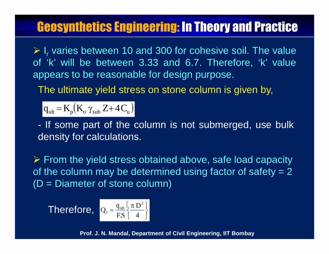
Ir varies between 10 and 300 for cohesive soil. The valueof ‘k’ will be between 3.33 and 6.7. Therefore, ‘k’ valueappears to be reasonable for design purpose.The ultimate yield stress on stone column is given by,
usubopult C 4 Z KKq
- If some part of the column is not submerged, use bulkdensity for calculations.
From the yield stress obtained above, safe load capacity of the column may be determined using factor of safety = 2 (D = Diameter of stone column)
Therefore,
4D
S.FqQ
2ult
1
Prof. J. N. Mandal, Department of Civil Engineering, IIT Bombay
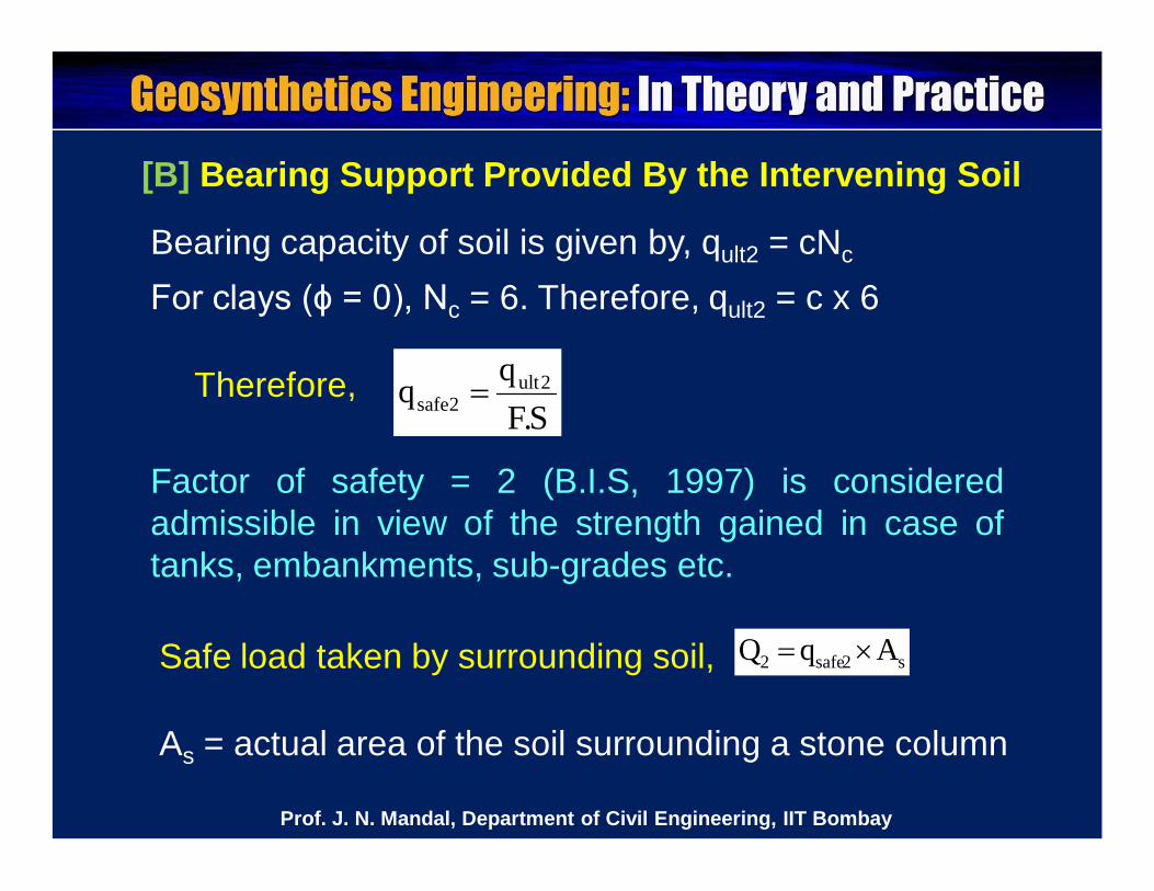
[B] Bearing Support Provided By the Intervening Soil
Bearing capacity of soil is given by, qult2 = cNc
For clays (ɸ = 0), Nc = 6. Therefore, qult2 = c x 6
Therefore,S.F
qq 2ult2safe
Factor of safety = 2 (B.I.S, 1997) is consideredadmissible in view of the strength gained in case oftanks, embankments, sub-grades etc.
Safe load taken by surrounding soil, s2safe2 AqQ
As = actual area of the soil surrounding a stone column
Prof. J. N. Mandal, Department of Civil Engineering, IIT Bombay

Let’s consider triangular pattern of stone columns havingspacing ‘S’ between them.
2e S 0.866 S 60 sin SA
Area of intervening soil for each column is given by,
4D -S 866.0A
22
s
Therefore, safe load is calculated as,
4D S 866.0qQ
22
2safe2
Ae = total influence area including the column
Prof. J. N. Mandal, Department of Civil Engineering, IIT Bombay

[C] Surcharge Effect
Due to load when stone column dilates, some part of loadwill be shared by the surrounding soil.
Consideration of soil under this load results in the increaseof its strength providing additional lateral resistance againstbulging of stone column.
The analogy for expansion of cylindrical cavity (Vesic,1972) and bulging failure phenomenon of granular pile in ahomogeneous, isotropic and infinite soil mass has been usedto find increase in capacity due to additional soil resistance.
Prof. J. N. Mandal, Department of Civil Engineering, IIT Bombay

Increase in mean radial stress (Δσr')
o2safe
r K 21 S.F
q'
Increase in ultimate cavity expansion stress,
'F K q rpro
Fq' is the Vesic’s (1972) dimensionless cylindrical cavity
expansion factor. It depends upon ϕ and reduced rigidityindex.
For ϕ = 0o, Fq' = 1 (Vesic, 1972)
Therefore, increase in Yield stress,
column stone of area c/s q ro3ult
Prof. J. N. Mandal, Department of Civil Engineering, IIT Bombay

Allowing a factor of safety = 2 to account for variation inKo, Cu and cross-sectional area, the increase inpermissible load of column,
4D
S.Fq
Q2
3ult3
[D] Effect of Geosynthetics Encasement
- Geosynthetics encased stone columnanalogues to thin cylinder
D = internal diameter, t = thickness, and L = lengthp = internal pressure intensity
Prof. J. N. Mandal, Department of Civil Engineering, IIT Bombay

Let us consider a longitudinal section XX through axisdividing the shell into two halves A and B.
Let us consider two elementary strips subtending an angleδθ at the centre at an angle θ on either side of the verticalthrough the centre (Ramamrutham and Narayanan, 2008).
Prof. J. N. Mandal, Department of Civil Engineering, IIT Bombay

The normal force acting on each strip is given by,δpn = p r δθ L
Resultant of the two normal forces on the two elementalstrips acting vertically i.e. normal to XX is,δp = 2 p r δθ L cosθ
Total force normal to XX on one side of XX= Total bursting force
p Lr 2
Cos Lr p 2P0
P = Projected area x Intensity of radial pressure
Prof. J. N. Mandal, Department of Civil Engineering, IIT Bombay

Let F1 is the intensity of tensile stress induced inGeosynthetics material across section.
Then resisting force offered by section = F1 x 2 x L x t
Equating the bursting force to resisting force,F1 x 2 x L x t = 2 x r x L x p
t2D pF1 D
F t 2p 1Hoop stress,
Longitudinal stress is given by (For Geosynthetic casing, F2 = 0)
t4D pF2
Prof. J. N. Mandal, Department of Civil Engineering, IIT Bombay

Greatest shear stress qmax is given by,
t2D p
2FF
q 21max
ncecircumfere Originalncecircumferein Changestrain tialCirumferen
ε1 = circumferential strain
1
D D D DD D
Also, Circumferential strain can be expressed as,
mEF
EF 21
1 E is Young’s modulus and 1/m isPoisson’s ration.
Prof. J. N. Mandal, Department of Civil Engineering, IIT Bombay

11
1
D2 t E
2 t ED
F pE
p
The developed resisting force for a given strain,
12 E Dfab
PPt
Therefore, safe load carried,
4D
S.FKP
Q p fab4
Factor of safety may be taken as 2.0
Prof. J. N. Mandal, Department of Civil Engineering, IIT Bombay

Total safe load carrying capacity of plane/ordinarystone column,
Qsafe1 = Q1 + Q2 + Q3
Total safe load carrying capacity of encased stonecolumn,
Qsafe2 = Q1 + Q2 + Q3 + Q4
Total number (N) of stone columns required,
safeQ load TotalN
The area per column is given by Nayak (1985),
Netc.) Embankment (Tank, Load of Area Column StonePer Area
Prof. J. N. Mandal, Department of Civil Engineering, IIT Bombay

Required spacing of stone columns for triangular pattern,
0.868Column Stoneper Area
Sreq
CU = 10 kN/m2
ɸ = 35ºSpacing = 1.5 mγsub = 5 kN/m3
BEARING CAPACITY OF PLANE & REINFORCED STONE COLUMNSTONE COLUMN DIAMETER IN M
0.5 0.6 0.7 0.8 0.9 1 1.1 1.2Q1 kN 17.75 26.50 37.35 50.45 65.97 84.05 104.86 128.54Q2 kN 52.56 49.97 46.91 43.38 39.37 34.89 29.95 24.53Q3 kN 15.22 21.91 29.82 38.95 49.30 60.86 73.64 87.64Q4 kN 14.49 17.39 20.29 23.19 26.08 28.98 31.88 34.78Qsafe1 kN 85.53 98.38 114.08 132.78 154.63 179.80 208.44 240.71Qsafe2 kN 100.02 115.77 134.37 155.97 180.72 208.79 240.32 275.49
Design example:
Prof. J. N. Mandal, Department of Civil Engineering, IIT Bombay

ENCASEMENTS
Different types of encasements can be prepared usinggeosynthetic reinforcements.
Bamboo is easily available and cheaper in India withrespect to polyester geogrid and also environmentfriendly.
Natural bamboo geogrid encasements can beprepared to encapsulate the stone columns.
Narrow bamboo sticks of 10 mm width with properfinishing were collected to prepare bamboo encasements(Dutta et al., 2012).
Prof. J. N. Mandal, Department of Civil Engineering, IIT Bombay

(a) Bamboo encasement (b) bamboo made encasement wrapped with jute geotextile (c) Polyester geogrid
encasement (After Dutta et al., 2012)
(a) (b) (c)
Prof. J. N. Mandal, Department of Civil Engineering, IIT Bombay

Tensile strength of the bamboo geogrid was determinedaccording to ASTM D4595-11 specification for wide-widthstrip method.
Wide width specimens of 200 mm width and 100 mmgauge length were prepared by attaching the narrowbamboo strips from both directions with adhesive.
Wide width bamboo grid specimens (a) before tensile test (b) after tensile test (ASTM D4595-11)
Prof. J. N. Mandal, Department of Civil Engineering, IIT Bombay

Wide width tensile strength test of polyester geogrid (ASTM D4595-11)
Prof. J. N. Mandal, Department of Civil Engineering, IIT Bombay

0
20
40
60
80
100
120
0 1 2 3 4 5 6 7 8 9 10
Ten
sile
str
engt
h (k
N/m
)
Strain (%)
Bamboo geogrid
0
5
10
15
20
25
30
35
0 5 10 15 20 25 30
Tens
ile s
treng
th (k
N/m
)
Strain (%)
Polyester geogrid
(a) (b)
Tensile strength versus strain curve of (a) bamboo geogrid (b) polyester geogrid
Prof. J. N. Mandal, Department of Civil Engineering, IIT Bombay

Material Properties ValueBamboo geogrid Mesh size 5 mm x5 mm
Ultimate tensile strength
110 kN/m
Ultimate stiffness 2200 kN/m
Polyester geogrid Mesh size 5 mm x5 mmUltimate tensile
strength32 kN/m
Ultimate stiffness 160 kN/m
Properties of geogrid
Prof. J. N. Mandal, Department of Civil Engineering, IIT Bombay

Axisymmetric finite element model (FEM) of encased stone column (After Dutta et al., 2012)
Prof. J. N. Mandal, Department of Civil Engineering, IIT Bombay

Effect of encasement stiffness on radial deformation:
0
50
100
150
200
250
300
350
400
450
500
0 4 8 12 16
Hei
ght (
mm
)
Radial deformation (mm)
OSC
ESC (160 kN/m)
ESC (2200 kN/m)
Radial deformation of stone column without and with encasement from finite element analysis
(After Dutta et al., 2012)
OSC = Ordinary stone column
ESC = Encased stone column
Bamboo geogrid = 2200 kN/m
Polyester geogrid = 160 kN/m
Prof. J. N. Mandal, Department of Civil Engineering, IIT Bombay
More uniform and minimum radial deformation isobtained with increasing stiffness of the encasements.
Ordinary stone column (OSC) fails by bulging withinalmost 2D length of the column with a significant radialdeformation of around 13 mm.
Using Polyester geogrid and Bamboo encasement radialdeformation reduces to 4 mm and 1.5 mm respectively.
Geogrid encasements provide excess lateral confiningpressure to the columns and prevent its radial deformation.
As the stiffness increases, more hoop tension getsgenerated in the encasement and it provides moreconfining pressure to the stone column.
Prof. J. N. Mandal, Department of Civil Engineering, IIT Bombay

Please let us hear from you
Any question?
Prof. J. N. Mandal, Department of Civil Engineering, IIT Bombay

Prof. J. N. Mandal
Department of civil engineering, IIT Bombay, Powai , Mumbai 400076, India. Tel.022-25767328email: [email protected]
Prof. J. N. Mandal, Department of Civil Engineering, IIT Bombay
Recommended