General Specification for Air-conditioning, Refrigeration, Ventilation and
Central Monitoring & Control System Installation
in Government Buildings of the Hong Kong Special Administrative Region
2012 Edition (Incorporating Corrigendum No. GSAC02-2012)
The 2012 edition (incorporating Corrigendum No. GSAC02-2012) of the
General Specification for Air-conditioning, Refrigeration, Ventilation and Central
Monitoring & Control System Installation has incorporated updates and revisions to
the 2012 edition (incorporating Corrigendum No. GSAC01-2012). Please refer to the
summary of major changes for revisions in comparison with the latter edition.
Electronic version of this 2012 edition (incorporating Corrigendum No.
GSAC02-2012) can be viewed on the ArchSD Internet homepage.
In view of the revisions and new additions, there will be an introductory period
of about 3 months in preparation for full implementation of this 2012 edition
(incorporating Corrigendum No. GSAC02-2012) as contract document by 1
November 2014. In summary,
For tenders to be invited on or after 1 November 2014, this 2012 edition
(incorporating Corrigendum No. GSAC02-2012) shall be used.
Existing contracts (including contracts using previous editions tendered before 1
November 2014) will not be affected.
(8/2014)

Page 1 of 11 AC_GS 2012 Edition
Major Changes GSAC02-2012
MAJOR CHANGES IN THE CORRIGENDUM (NO. GSAC02-2012) OF THE
GENERAL SPECIFICATION FOR AIR-CONDITIONING, REFRIGERATION, VENTILATION AND CENTRAL
MONITORING & CONTROL SYSTEM INSTALLATION
IN GOVERNMENT BUILDINGS OF THE HONG KONG SPECIAL ADMINISTRATIVE REGION
2012 EDITION
Old Ref. No. New Ref. No. Major Changes
PART A - SCOPE AND GENERAL REQUIREMENTS
SECTION A2 - STATUTORY OBLIGATIONS AND OTHER REGULATIONS
A2.1.1 A2.1.1 Delete “and”
A2.1.1 A2.1.1 Replace “.” to “; and”
A2.1.1 A2.1.1 Add “(m) Buildings Energy Efficiency Ordinance (Cap. 610), and other subsidiary legislation made
under the Ordinance.”
SECTION A4 - DRAWINGS AND MANUALS
A4.2.2 A4.2.2 Replace “ISO 5457:1999” by “ISO 5457:1999/Amd 1:2010”
A4.3.2 A4.3.2 Replace “ISO 5457:1999” by “ISO 5457:1999/Amd 1:2010”
PART B - GENERAL TECHNICAL REQUIREMENTS (INSTALLATION METHODOLOGY)
SECTION B2 - DUCTWORK
B2.1 B2.1 Replace “performance” by “inspection”
B2.1 B2.1 Replace “All ducts” by “The ducting system”
B2.2 B2.2 Delete “or erection”
B2.2 B2.2 Replace “assembly” by “unit”
B2.2 B2.2 Replace “Building Ordinance” by “Buildings Ordinance”
B2.4 B2.4 Delete “to BS 476-23:1987”
B2.5 B2.5 Add “ , or shall be made with clip and complete with aluminium tape as approved by the Architect”
B2.5 B2.5 Replace “sealant and” by “installation details and”
Page 2 of 11 AC_GS 2012 Edition
Major Changes GSAC02-2012
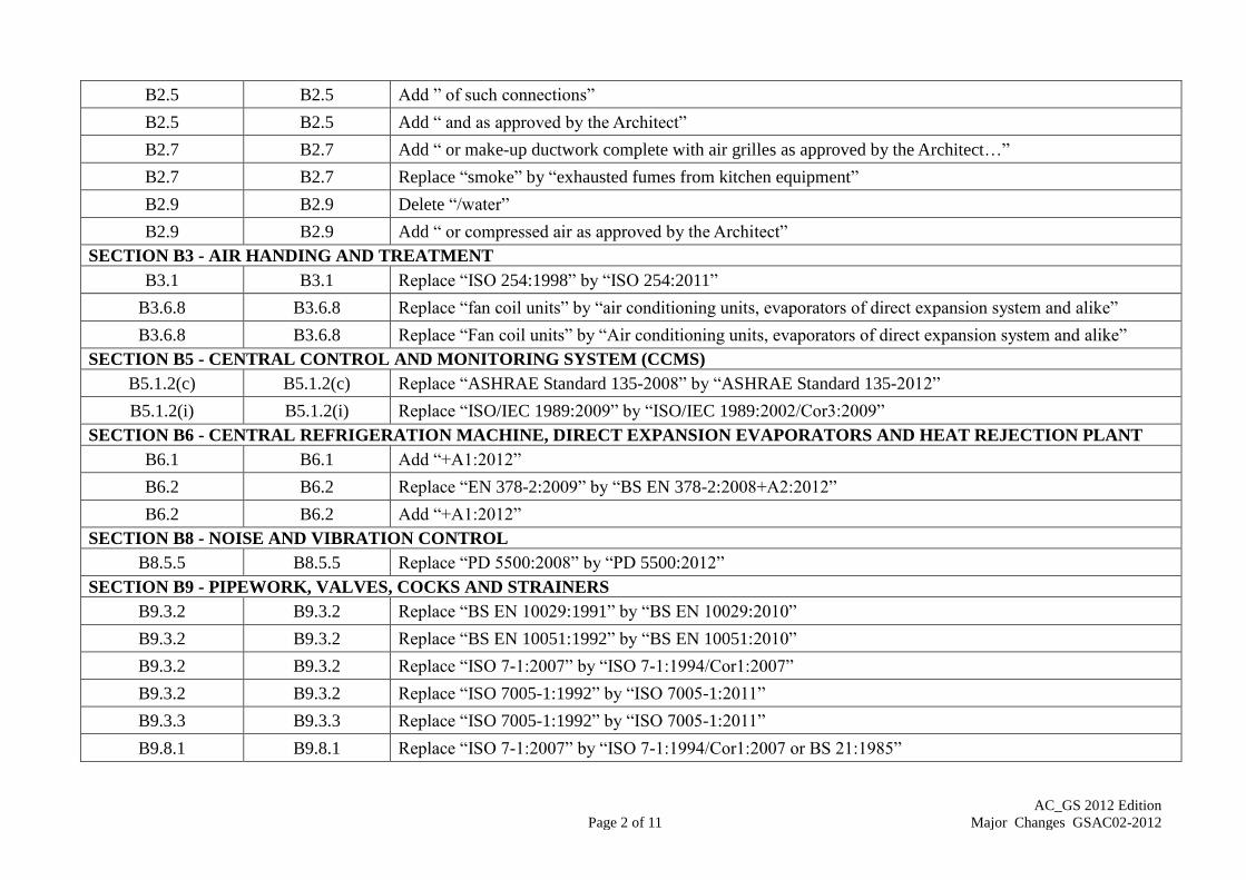
B2.5 B2.5 Add ” of such connections”
B2.5 B2.5 Add “ and as approved by the Architect”
B2.7 B2.7 Add “ or make-up ductwork complete with air grilles as approved by the Architect…”
B2.7 B2.7 Replace “smoke” by “exhausted fumes from kitchen equipment”
B2.9 B2.9 Delete “/water”
B2.9 B2.9 Add “ or compressed air as approved by the Architect”
SECTION B3 - AIR HANDING AND TREATMENT
B3.1 B3.1 Replace “ISO 254:1998” by “ISO 254:2011”
B3.6.8 B3.6.8 Replace “fan coil units” by “air conditioning units, evaporators of direct expansion system and alike”
B3.6.8 B3.6.8 Replace “Fan coil units” by “Air conditioning units, evaporators of direct expansion system and alike”
SECTION B5 - CENTRAL CONTROL AND MONITORING SYSTEM (CCMS)
B5.1.2(c) B5.1.2(c) Replace “ASHRAE Standard 135-2008” by “ASHRAE Standard 135-2012”
B5.1.2(i) B5.1.2(i) Replace “ISO/IEC 1989:2009” by “ISO/IEC 1989:2002/Cor3:2009”
SECTION B6 - CENTRAL REFRIGERATION MACHINE, DIRECT EXPANSION EVAPORATORS AND HEAT REJECTION PLANT
B6.1 B6.1 Add “+A1:2012”
B6.2 B6.2 Replace “EN 378-2:2009” by “BS EN 378-2:2008+A2:2012”
B6.2 B6.2 Add “+A1:2012”
SECTION B8 - NOISE AND VIBRATION CONTROL
B8.5.5 B8.5.5 Replace “PD 5500:2008” by “PD 5500:2012”
SECTION B9 - PIPEWORK, VALVES, COCKS AND STRAINERS
B9.3.2 B9.3.2 Replace “BS EN 10029:1991” by “BS EN 10029:2010”
B9.3.2 B9.3.2 Replace “BS EN 10051:1992” by “BS EN 10051:2010”
B9.3.2 B9.3.2 Replace “ISO 7-1:2007” by “ISO 7-1:1994/Cor1:2007”
B9.3.2 B9.3.2 Replace “ISO 7005-1:1992” by “ISO 7005-1:2011”
B9.3.3 B9.3.3 Replace “ISO 7005-1:1992” by “ISO 7005-1:2011”
B9.8.1 B9.8.1 Replace “ISO 7-1:2007” by “ISO 7-1:1994/Cor1:2007 or BS 21:1985”

Page 3 of 11 AC_GS 2012 Edition
Major Changes GSAC02-2012
B9.8.2 B9.8.2 Replace “ISO 7005-1:1992” by “ISO 7005-1:2011”
B9.8.5 B9.8.5 Replace “two or more malleable iron castings” by “two or more malleable or ductile iron castings”
B9.8.5 B9.8.5 Replace “shall be malleable iron castings” by “shall be malleable or ductile iron castings”
B9.9.1 B9.9.1 Add “or BS EN 1254-1 to BS EN 1254-4 for water distribution purpose and ASME B16.22 for refrigeration
copper fittings for refrigerant distribution purpose”
B9.9.1 B9.9.1 Replace “ISO 7005-1:1992” by “ISO 7005-1:2011”
B9.15.3 B9.15.3 Replace “ISO 9461:1992” by “BS EN 1982:2008”
B9.15.3 B9.15.3 Replace “BS EN 1561:1997” by “BS EN 1561:2011”
B9.15.3 B9.15.3 Replace “ISO 7-1:2007” by “ISO 7-1:1994/Cor1:2007”
B9.15.3 B9.15.3 Replace “ISO 7005-1:1992” by “ISO 7005-1:2011”
SECTION B11 - THERMAL INSULATION
B11.5.4 B11.5.4 Replace “NFPA-90A:2009” by “NFPA-90A:2012”
B11.6.3(c) B11.6.3(c) Replace “D-579-09” by “D579/D579M-10”
B11.6.4(d) B11.6.4(d) Replace “NFPA-90A:2009” by “NFPA-90A:2012”
B11.8.2 B11.8.2 Replace “BS 4800:1989” by “BS 4800:2011”
SECTION B12 - UNITARY AIR-CONDITIONER
B12.1.2 B12.1.2 Replace “(ISO) Standards 5151:1994” by “(ISO) Standards 5151:2010”
B12.1.2 B12.1.2 Replace “13253:1995” by “13253:2011”
SECTION B13 - WATER HANDLING EQUIPMENT
B13.1 B13.1 Replace “BS EN ISO 9906:2000” by “BS EN ISO 9906:2012”
PART C - GENERAL TECHNICAL REQUIREMENTS (MATERIAL AND EQUIPMENT SPECIFICATION)
SECTION C1 - AIR CLEANING EQUIPMENT
C1.1.1 C1.1.1 Replace “ANSI/ASHRAE Standard 52.2-2010” by “ANSI/ASHRAE Standard 52.2-2012”
C1.2.1(b) C1.2.1(b) Replace “ANSI/ASHRAE Standard 52.2-2010” by “ANSI/ASHRAE Standard 52.2-2012”
C1.3 C1.3 Replace “ANSI/ASHRAE Standard 52.2-2010” by “ANSI/ASHRAE Standard 52.2-2012”
C1.4 C1.4 Replace “ANSI/ASHRAE Standard 52.2-2010” by “ANSI/ASHRAE Standard 52.2-2012”

Page 4 of 11 AC_GS 2012 Edition
Major Changes GSAC02-2012
C1.5 C1.5 Replace “ANSI/ASHRAE Standard 52.2-2010” by “ANSI/ASHRAE Standard 52.2-2012”
C1.6 C1.6 Replace “ANSI/ASHRAE Standard 52.2-2010” by “ANSI/ASHRAE Standard 52.2-2012”
C1.7 C1.7 Replace “ANSI/ASHRAE Standard 52.2-2010” by “ANSI/ASHRAE Standard 52.2-2012”
C1.8 C1.8 Replace “ANSI/ASHRAE Standard 52.2-2010” by “ANSI/ASHRAE Standard 52.2-2012”
C1.9 C1.9 Replace “ANSI/ASHRAE Standard 52.2-2010” by “ANSI/ASHRAE Standard 52.2-2012”
C1.10 C1.10 Replace “ANSI/ASHRAE Standard 52.2-2010” by “ANSI/ASHRAE Standard 52.2-2012”
C1.12 C1.12 Replace “ANSI/ASHRAE Standard 52.2-2010” by “ANSI/ASHRAE Standard 52.2-2012”
C1.14 C1.14 Replace “ANSI/ASHRAE Standard 52.2-2010” by “ANSI/ASHRAE Standard 52.2-2012”
C1.14 C1.14 Replace “UL 867:2000” by “UL 867:2012”
C1.14 C1.14 Replace “UL 710:1995” by “UL 710:2012”
C1.14 C1.14 Replace “ANSI/ASHRAE Standard 52.2-2010” by “ANSI/ASHRAE Standard 52.2-2012”
C1.14 C1.14 Replace “UL 867:2000” by “UL 867:2012”
C1.16 C1.16 Replace “BS EN 61000-6-3:2007” by “BS EN 61000-6-3:2007+A1:2011”
C1.16 C1.16 Replace “UL 867:2000” by “UL 867:2012”
C1.17 C1.17 Replace “UL 1995:2005” by “UL 1995:2011”
SECTION C2 - DUCTWORK AND ACCESSORIES
C2.2 C2.2 Delete ” Copy of the proposed software details shall be submitted for approval prior to production.”
C2.2 C2.2 Delete “Copy of the proposed Numerical Control Cutting Machines details shall be submitted for approval
prior to production.”
C2.6.2 C2.6.2 Replace “NFPA-90A:2009” by “NFPA-90A:2012”
C2.6.2 C2.6.2 Replace “90B:2009” by “90B:2012”
C2.7.1.3 C2.7.1.3 Replace “BS EN ISO 5659-2:2006” by “BS EN ISO 5659-2:2012”
C2.7.2.3 C2.7.2.3 Replace “BS EN ISO 5659-2:2006” by “BS EN ISO 5659-2:2012”
C2.8 C2.8 Add “and comply with BS EN 1751:1999”
C2.8 C2.8 Delete “Air leakage rate for dampers shall be tested according to BS EN 1751:1999 Section 3 when the

Page 5 of 11 AC_GS 2012 Edition
Major Changes GSAC02-2012
damper is in the closed position. For dampers installed for shut- off purpose, the maximum air leakage rate
shall be tested according to BS EN 1751:1999 Section 4.”
C2.8 C2.8 Delete “Bearings shall be of nylon material and”
C2.8 C2.8 Add “except the volume control dampers of which the adjustment can be made outside the ductwork”
C2.11.1 C2.11.1 Replace “Building Ordinance” by “Buildings Ordinance”
C2.11.1(b) C2.11.1(b) Replace “Code of Practice for FRC” by “Code of Practice for Fire Safety in Building 2011”
C2.11.1 C2.11.1 Replace “NFPA-90A:2009” by “NFPA-90A:2012”
C2.11.1 C2.11.1 Add “or electro thermal link (ETL)”
C2.11.2 C2.11.2 Replace “electromagnetic device with power rating of not more than 3.5W” by “actuator”
C2.11.2 C2.11.2 Delete “to BS 476-23:1987”
C2.11.2 C2.11.2 Delete “to BS 476-23:1987”
C2.12 C2.12 Replace “in case of fire” by “when there is a fire or the air handling unit is shut off”
C2.12 C2.12 Replace “detectors” by “control”
C2.12 C2.12 Delete “Section 4”
C2.15 C2.15 Add “as recommended”
SECTION C3 - AIR HANDLING AND TREATMENT EQUIPMENT
C3.1.4(b) C3.1.4(b) Replace “BS ISO 10816-1:2009” by “BS ISO 10816-1:1995/Amd 1:2009”
C3.2.8 – (1) C3.2.8 – (1) Replace “BS EN 779:2002” by “BS EN 779:2012”
C3.2.8 – (2) C3.2.8 – (2) Replace “BS EN 779:2002” by “BS EN 779:2012”
C3.6.1(b) C3.6.1(b) Replace “BS EN 779:2002” by “BS EN 779:2012”
C3.6.1(c) C3.6.1(c) Delete “The fan motor shall be of the single phase … with three speed tapped windings”
C3.6.1(d) Add “The fan motor shall be of the single phase permanent split capacitor type provided with three speed
tapped windings, or brushless direct current (BLDC) type provided with low noise pulse width modulation
for variable speed control as specified in the Particular Specification.”
C3.6.1(e) Add the requirement of brushless direct current (BLDC) type fan coil unit

Page 6 of 11 AC_GS 2012 Edition
Major Changes GSAC02-2012
C3.6.1(d) C3.6.1(f) Re-number the clause
C3.6.1(e) C3.6.1(g) Re-number the clause
C3.6.5 C3.6.5 Replace “and heating/cooling mode selector as specified” to “with heating/cooling mode selector as required
for standalone control, or connected to CCMS as specified”; and add the control requirement for BLDC
motor
C3.13.1(a) C3.13.1(a) Delete “ISO 5220:1984,”
C3.13.1(d) C3.13.1(d) Replace “NFPA-90A:2009” by “NFPA-90A:2012”
C3.13.1(d) C3.13.1(d) Replace “ISO 1182:2002” by “ISO 1182:2010”
C3.14.3(b) C3.14.3(b) Replace “NFPA-90A:2009” by “NFPA-90A:2012”
C3.14.3(b) C3.14.3(b) Replace “ISO 1182:2002” by “ISO 1182:2010”
SECTION C5 - CENTRAL CONTROL AND MONITORING SYSTEM (CCMS)
C5.3(a) C5.3(a) Replace “ASHRAE. Standard 135-2008” by “ASHRAE. Standard 135-2012”
C5.3(h) C5.3(h) Replace “ISO/IEC 1989:2009” by “ISO/IEC 1989:2002/Cor 1:2009”
C5.10 C5.10 Replace “0-20mA” to “4-20mA”
SECTION C6 - CENTRAL REFRIGERATION MACHINE, DIRECT EXPANSION EVAPORATOR AND HEAT REJECTION PLANT
C6.1 C6.1 Replace “AHRI Standard 550/590:2003, BS EN 14511-1:2007 to BS EN 14511-4:2007” by “AHRI Standard
550/590:2012, BS EN 14511-1:2011 to BS EN 14511-4:2011”
C6.1 C6.1 Replace “the compressor speed shall not exceed 200 revolutions per second” by “the compressor speed shall
not exceed 250 revolutions per second”
C6.1 C6.1 Replace “AHRI Standard 550/590:2003, BS EN 14511-1:2007 to BS EN 14511-4:2007” by “AHRI Standard
550/590:2012, BS EN 14511-1:2011 to BS EN 14511-4:2011”
C6.1 C6.1 Delete “15%” of full capacity for data measurement in characteristic curves and sound pressure level
characteristic curves
C6.5.1(c) C6.5.1(c) Replace “which will control at any point from 30 to 100% of full duty by inlet guide vane and/or variable
speed control without inducing a surge condition” by “which will control at any point from 25% to 100% of

Page 7 of 11 AC_GS 2012 Edition
Major Changes GSAC02-2012
full duty by inlet guide vane (for constant motor speed) or inlet guide vane and variable speed control (for
variable motor speed) without inducing a surge condition”.
C6.5.2(a) C6.5.2(a) Replace the paragraph by “The compressor shall be of semi-hermetic type and directly driven by an electric
motor”
C6.5.2(j) C6.5.2(j) Replace “30%” by “25%”
C6.6.4 C6.6.4 Replace “which will control at any point between 20 and 100% of full duty” by “which will control at any
point between 25% and 100% of full duty”
C6.6.4 C6.6.4 Replace “minimum step capacity shall be maximum 20% of full load” by “minimum step capacity shall be
maximum 25% of full load”
C6.7.2 C6.7.2 Replace the items (a) to (h) in the paragraph by
(a) Stop valves on refrigerant discharge and suction;
(b) Refrigerant pressure gauges as Clause C6.4.7(b);
(c) High and low pressure safety cut-outs as Clause C6.4.7(e);
(d) Filter dryer
(e) Instrument mounting as Clause C6.4.7(h)
Alternatively, pressure measurements read from the display panel of the chiller is acceptable.
C6.11.1 C6.11.1 The whole paragraph is rephrased.
C6.14.2 C6.14.2 Add “For flooded type evaporator…”
C6.17 C6.17 The whole paragraph is rephrased.
C6.20.2(a) C6.20.2(a) Replace “BS EN 12735-1:2001 and BS EN 12735-2:2001” by “BS EN 12735-1:2010 and BS EN
12735-2:2010 or other international recognized standard”
C6.20.2(b) C6.20.2(b) Add “or other international recognized standard”
C6.20.3 C6.20.3 Replace “ANSI / ASME Code B31.5:2006” by “ANSI / ASME Code B31.5:2010”
C6.21.1 C6.21.1 Replace “BS EN 378-2:2009” by “BS EN 378-2:2008+A2:2012”

Page 8 of 11 AC_GS 2012 Edition
Major Changes GSAC02-2012
C6.21.8 C6.21.8 Replace “colour moisture indicator” by “sight glass”
C6.23.2 C6.23.2 Replace “All the waste heat shall be.…” by “Waste heat shall be….”
C6.23.4 C6.23.4 Add “or plate type”
C6.23.6 C6.23.6 Delete “Multiple circuit dry expansion” and Add “For shell and tube design”
C6.24.2 C6.24.2 Replace “Air-to-water or water-to-water heat pump shall be operating in reverse cycle” by “Air-to-water
heat pump shall be operating in reverse refrigeration cycle whilst water-to-water heat pump makes use of the
building cooling load as a heat source for water heating”.
C6.25 C6.25 The first paragraph is rephrased
C6.28.3(a) C6.28.3(a) Replace “BS EN 12975-1:2006” by “BS EN 12975-1:2006+A1:2010”
C6.28.4 C6.28.4 Replace “BS PD 5500:2008” by “BS PD 5500:2012”
SECTION C8 - NOISE AND VIBRATION CONTROL
C8.5.2 C8.5.2 Replace “BS PD 5500:2008” by “BS PD 5500:2012”
C8.5.2 C8.5.2 Replace “ISO 7-1:2007” by “ISO 7-1:1994/Cor1:2007”
C8.7 C8.7 Replace “ASTM C1071-05” by “ASTM C1071-12”
SECTION C9 - PIPE MATERIAL, VALVES, COCKS AND STRAINERS
C9.3.2 C9.3.2 Replace “Grooved ends butterfly valves completed with full-lug may also be accepted” by “Butterfly valves
in connection with wafer, full-lug, flange or grooved ends may also be accepted”
C9.3.2(a) C9.3.2(a) Add “or BS EN 593:2009 +A1:2011”
C9.3.2(b) C9.3.2(b) Delete “such as Underwriters Laboratory or Factory Mutual Research”
C9.3.2(d) C9.3.2(d) Delete “EPDM” and replace by “protective”
C9.4 C9.4 Replace “BS EN 1561:1997” by “BS EN 1561:2011”
C9.5 – (3)(ii) C9.5 – (3)(ii) Add “or BS 3505:1986”
C9.5 – (5)(ii) C9.5 – (5)(ii) Add “or BS 3505:1986”
C9.5 – (5)(iii) C9.5 – (5)(iii) Replace “BS EN 545:2006” by “BS EN 545:2010”

Page 9 of 11 AC_GS 2012 Edition
Major Changes GSAC02-2012
Add “For screw-on flanges connection, thickness grade of Class K12”
C9.5 – (6)(i) C9.5 – (6)(i) Add “or BS 3505:1986”
C9.5 – (7)(i) C9.5 – (7)(i) Add “BS 3505:1986 or”
C9.5 – (7)(a) C9.5 – (7)(a) Replace “BS EN 1057:2006” by “BS EN 1057:2006+A1:2010”
C9.5 – (7)(a) C9.5 – (7)(a) Add “Refrigeration copper tubes to BS EN 12735-1 (tubes for piping systems) or 12735-2 (tubes for
equipment) for refrigerant distribution purpose”
C9.5 – (7)(c) C9.5 – (7)(c) Add”BS EN”
C9.5 – (7)(c) C9.5 – (7)(c) Replace “ISO 7-1:2007” by “ISO 7-1:1994/Cor1:2007”
C9.5 – (7)(c) C9.5 – (7)(c) Replace “ISO 7268:1984” by “ISO 7268:1983/Amd 1:1984”
C9.5 – (7) Note 2 C9.5 – (7) Note 2 Add “or BS 3505:1986”
C9.5 – (7) Note 4 C9.5 – (7) Note 4 Replace “BS EN 545:2006” by “BS EN 545:2010”
C9.5 – (7) Note 4 C9.5 – (7) Note 4 Replace “BS EN 197-1:2000” by “BS EN 197-1:2011”
C9.5 – (7) Note 4 C9.5 – (7) Note 4 Replace “BS EN 598:2009” by “BS EN 598:2007+A1:2009”
C9.5 – (7) Note 5 C9.5 – (7) Note 5 Add “BS 3505:1986 or”
C9.5 – (7) Note 5 C9.5 – (7) Note 5 Replace “BS EN ISO 1452-3:2009” by “BS EN ISO 1452-3:2010”
C9.8 C9.8 Add “or Y-type strainer of appropriate size as approved by the Architect”
SECTION C10 - SYSTEM MONITORING INSTRUMENT
C10.4 C10.4 Add “or alcohol”
C10.5 C10.5 Add “or anti-corrosive painted”
C10.7 C10.7 Add “or BS 7350:1990”
C10.8 C10.8 Replace “BS EN 61000-6-3:2007” by “BS EN 61000-6-3:2007+A1:2011”
SECTION C11 - THERMAL INSULATION
C11.1.1 C11.1.1 Replace “BS 5970:2001” by “BS 5970:2012”
C11.2.1(d) C11.2.1(d) Replace “BS ISO 1922:2001” by “BS ISO 1922:2012”
C11.2.1(e) C11.2.1(e) Replace “BS ISO 1922:2001” by “BS ISO 1922:2012”

Page 10 of 11 AC_GS 2012 Edition
Major Changes GSAC02-2012
C11.2.1(e) C11.2.1(e) Replace “ISO 4590:2003” by “BS EN ISO 4590:2003”
C11.2.1(f) C11.2.1(f) Replace “BS ISO 1922:2001” by “BS ISO 1922:2012”
C11.2.4(g) C11.2.4(g) Replace “ISO 5659-2:2006” by “ISO 5659-2:2012”
C11.2.8(e) C11.2.8(e) Replace “BS ISO 1922:2001” by “BS ISO 1922:2012”
C11.2.8(e) C11.2.8(e) Replace “ISO 4590:2003” by “BS EN ISO 4590:2003”
C11.4.2(d) C11.4.2(d) Replace “ASTM E96 /E96M-05” by “ASTM E96 /E96M-12”
C11.4.3(b) C11.4.3(b) Replace “ASTM D882-09” by “ASTM D882-12”
C11.5.2 – (1) Note 1 C11.5.2 – (1)
Note 1
Replace “BS EN 1057:2006” by “BS EN 1057:2006+A1:2010”
SECTION C13 - WATER HANDLING EQUIPMENT
C13.1.3(a) C13.1.3(a) Replace “BS EN 1561:1997” by “BS EN 1561:2011”
C13.1.3(d) C13.1.3(d) Replace “BS EN 1561:1997” by “BS EN 1561:2011”
C13.3.3(a) C13.3.3(a) Replace “BS EN 1561:1997” by “BS EN 1561:2011”
C13.3.3(b)(ii) C13.3.3(b)(ii) Replace “BS EN 13835:2002” by “BS EN 13835:2012”
C13.3.3(b)(ii) C13.3.3(b)(ii) Replace “ISO 2892:2009” by “ISO 2892:2007/Cor 1:2009”
C13.5.3 C13.5.3 Replace “BS EN 60079-0:2009” by “BS EN 60079-0:2012”
C13.12 C13.12 Replace “ISO 7005-1:1992” by “ISO 7005-1:2011”
C13.14 C13.14 Replace “BS EN 1561:1997” by “BS EN 1561:2011”
C13.15.2(d) C13.15.2(d) Replace “ISO 7005-1:1992” by “ISO 7005-1:2011”
PART D - INDOOR AIR QUALITY (IAQ)
SECTION D.1 - GENERAL
D.1 D.1 Replace “Building Ordinance” by “Buildings Ordinance”
SECTION D.5 - EQUIPMENT/ MATERIALS – PART C: TREATMENT AND CONDITIONING MEDIA
D.5.1.1(d)(viii) D.5.1.1(d)(viii) Replace “NFPA-90A:2009” by “NFPA-90A:2012”
D.5.1.1(e)(ii) D.5.1.1(e)(ii) Replace “ANSI/ASHRAE Standard 52.2-2010” by “ANSI/ASHRAE Standard 52.2-2012”
PART G - PAINTING, FINISHING AND PROTECTIVE TREATMENT

Page 11 of 11 AC_GS 2012 Edition
Major Changes GSAC02-2012
SECTION G.3 - IDENTIFICATION OF PIPELINES
G.3 G.3 Replace “BS 4800:1989” by “BS 4800:2011”
G.3 G.3 Replace “ISO 3864-1:2002” by “ISO 3864-1:2011”
G.3 G.3 Replace “ISO 3864-1:2002” by “ISO 3864-1:2011”
SECTION G.4 - SCHEDULE OF COLOURS
G.4 G.4 Replace “BS 4800:1989” by “BS 4800:2011”
PART H - INSPECTION, TESTING AND COMMISSIONING
SECTION H.4 - OFF-SITE TESTS
H.4.1 H.4.1 Replace “ISO 5801:2008” by “ISO 5801:2007/Cor 1:2008”
H.4.1 H.4.1 Replace “ISO 5136:2009” by “BS EN ISO 5136:2009”
H.4.1 H.4.1 Replace “ISO 1940-2:1997” by “ISO 21940-14:2012”
H.4.2 H.4.2 Replace “BS EN ISO 9906:2000” by “BS EN ISO 9906:2012”
.H.4.3 H.4.3 Replace “BS EN 60034-1:2004” by “BS EN 60034-1:2010”
H.4.6 H.4.6 Replace “BS EN 60335-1:2006” by “BS EN 60335-1:2012”
H.4.6 H.4.6 Replace “BS EN 60669-1:2008” by “BS EN 60669-1:1999+A2:2008”
H.4.7 H.4.7 Replace “BS EN 378-2:2009” by “BS EN 378-2:2008+A2:2012”
H.4.7 H.4.7 Replace “BS EN 378-3:2008” by “BS EN 378-3:2008+A1:2012”
H.4.7 H.4.7 Replace “BS EN 378-4:2008” by “BS EN 378-4:2008+A1:2012”

Page 1 of 55
AC_GS 2012 Edition
Corrigendum GSAC02-2012
ARCHITECTURAL SERVICES DEPARTMENT
BUILDING SERVICES BRANCH
GENERAL SPECIFICATION FOR
AIR-CONDITIONING, REFRIGERATION,
VENTILATION AND CENTRAL MONITORING & CONTROL
SYSTEM INSTALLATION
IN GOVERNMENT BUILDINGS OF
THE HONG KONG SPECIAL ADMINISTRATIVE REGION
2012 EDITION
Corrigendum No. GSAC02 - 2012
(August 2014)
The following clauses are amended in the above General Specification.
Clauses
PART A - SCOPE AND GENERAL REQUIREMENTS
SECTION A2
STATUTORY OBLIGATIONS AND OTHER REGULATIONS
A2.1 STATUTORY OBLIGATIONS AND OTHER REQUIREMENTS
A2.1.1 All Enactments and Regulations, in particular, the A/C Contractor’s
attention is drawn to the followings:
(k) Dangerous Goods Ordinance (Cap. 295), and other subsidiary
legislation made under the Ordinance;
(l) Places of Public Entertainment Ordinance (Cap. 172), and other
subsidiary legislation made under the Ordinance; and
(m) Buildings Energy Efficiency Ordinance (Cap. 610), and other
subsidiary legislation made under the Ordinance.

Page 2 of 55
AC_GS 2012 Edition
Corrigendum GSAC02-2012
SECTION A4
DRAWINGS AND MANUALS
A4.2 INSTALLATION DRAWINGS
A4.2.2 Size of Installation Drawings
Drawings submitted by the A/C Contractor shall only be of standard sizes
from A0 to A4 or B1 size as stipulated in ISO 5457:1999/Amd 1:2010.
A4.3 AS-BUILT DRAWINGS
A4.3.2 Size of As-built Drawings
As-built drawings shall only be of standard sizes of A0, A1 or B1 size as
stipulated in ISO 5457:1999/Amd 1:2010. Smaller size (A2 to A4) is
accepted for installation drawings.
PART B - GENERAL TECHNICAL REQUIREMENTS
(INSTALLTION METHODOLOGY)
SECTION B2
DUCTWORK
B2.1 GENERAL
Any damaged ductwork found shall be replaced. All inspection tests carried out
in factory are part of the quality control process and shall in no way be treated as
substitution of the field tests required on Site.
The ducting system shall be complete with all necessary supports, access doors,
dampers, fire dampers, cleaning points and test holes.
B2.2 DESIGN AND ACCESSORIES
Perforated rivets shall not be used in manufacture of ductwork. Generally, the
use of self tapping screws is not allowed. Where the use of other fastenings is
impracticable, self-tapping screws may be used subject to the written approval
of the Architect.

Page 3 of 55
AC_GS 2012 Edition
Corrigendum GSAC02-2012
Duct connections between individual components of an air handling unit and
connections between an assembly and a ductwork system shall be made with
angle flanged joints. Removable sections shall be provided for access of
cleaning and maintenance. All joints shall be made perfectly airtight and
proprietary duct-flange or angle duct-flange shall be used for all duct-joints and
for connection to plants.
All ductwork installed in the protected areas or lobbies shall be properly
enclosed in fire-rated enclosure in according to the requirement of the FSD and
Buildings Ordinance. All fire-rated enclosure shall have fire rating meeting the
requirements of the FSD and Buildings Ordinance, but shall in no case be less
than 2 hours.
B2.4 FLEXIBLE DUCT JOINTS
Flexible joints shall consist of, or be externally protected by, material having a
fire penetration time of at least 15 minutes when tested in accordance with BS
476-20:1987 and shall comply with BS 476-7:1997, Section 2, Class 1 (surface
of very low flame spread).
B2.5 FLEXIBLE DUCTWORK
Joints at flexible duct connections shall be made with a sealant which
permanently retains adhesion and elasticity throughout the design working
temperature range, or shall be made with clip and complete with aluminium tape
as approved by the Architect. The installation details and method of application
of such connections shall be in accordance with the ductwork manufacturer’s
recommendations and as approved by the Architect.
B2.7 EXTRACT HOODS AND VALANCES FOR KITCHENS
Kitchen exhaust hood should be completed with make-up air grilles or make-up
ductwork complete with air grilles as approved by the Architect and constructed
in such position for the best efficiency in evacuating exhausted fumes from
kitchen equipment.
B2.9 DUCTWORK CLEANING POINTS
All joints shall be air tight to prevent leakage. Air leakage for cleaning points
shall comply with DW/143:2000 and all FSD requirements. The A/C Contractor

Page 4 of 55
AC_GS 2012 Edition
Corrigendum GSAC02-2012
shall also provide a set of proprietary type compressed air lance, disinfection
application lance and sampling probe which shall be suitable for use of leakage
test to the cleaning points. All operating and serving instruction manuals shall
be supplied with the set of equipment.
Interior of all ductwork shall be cleaned by rotating mechanical brush or
compressed air as approved by the Architect. All contaminants shall then be
removed by high efficiency vacuum pumps of sufficient degree of vacuum to
ensure removal of heavier particles.
SECTION B3
AIR HANDLING AND TREATMENT
B3.1 GENERAL
Fan V-belt drives shall comply with BS 3790:2006 (or related clauses of ISO
254:2011, ISO 1081:1995, ISO 1813:1998, ISO 4183:1995, ISO 4184:1992 &
ISO 5292:1995) and shall be capable of transmitting at least the rated output
with one belt removed. Minimum two belts per drive shall be used unless
otherwise specified. Pulleys shall be exactly aligned. The A/C Contractor shall
ensure that any holding down bolts grouted in by builders are positioned to the
correct alignment. Provision shall be made for positive adjustment of the
tension in V-belt drives.
B3.6 FAN COIL UNITS
B3.6.8 A second or additional larger stainless steel insulated drain pan shall
be provided for those air conditioning units, evaporators of direct
expansion system and alike installed in switchrooms, lift machine
rooms, UPS rooms, control rooms and other essential areas sensible to
water damage. A water overflow alarm indication shall be equipped
at conspicuous place outside the room or connected to CCMS.
Air conditioning units, evaporators of direct expansion system and
alike and it's associated piping and ducting should not be mounted
above essential electrical and control equipment such as switchboard,
lift machine, control panel, UPS, etc.
SECTION B5
CENTRAL CONTROL AND MONITORING SYSTEM (CCMS)

Page 5 of 55
AC_GS 2012 Edition
Corrigendum GSAC02-2012
B5.1 GENERAL REQUIREMENTS
B5.1.2 Compliance with Various Codes/ Standards
(c) ASHRAE Standard 135-2012 - A Data Communication
Protocol for Building Automation and Control Networks
(BACnet);
(i) International Organization for Standardization ISO/IEC 1989:
2002/Cor3:2009 - Information Technology – Programming
Languages – COBOL; and
SECTION B6
CENTRAL REFRIGERATION MACHINE, DIRECT EXPANSION EVAPORATORS
AND HEAT REJECTION PLANT
B6.1 GENERAL
Refrigerant leakage warning alarm in accordance with the current edition of
ANSI/ASHRAE Standard 15-2010 or BS EN 378-3:2008+A1:2012 shall be
installed if the refrigeration plant is installed in indoor environment.
B6.2 LAYOUT AND ISOLATION OF PLANT COMPONENTS
The plant layout shall be so arranged with physical division and valves such that
any plant component may be isolated for servicing without completely draining
the refrigerant or water circuits of the whole plant and shall follow the
ANSI/ASHRAE Standard 15-2010 or BS EN 378-2:2008+A2:2012 to BS EN
378-3:2008+A1:2012. All equipment shall be located within safety marking
perimeter. Clear floor safety marking in durable brilliant colour approved by the
Architect shall be provided.
SECTION B8
NOISE AND VIBRATION CONTROL
B8.5 PIPEWORK VIBRATION ISOLATION
B8.5.5 Flexible Metallic Hose

Page 6 of 55
AC_GS 2012 Edition
Corrigendum GSAC02-2012
For higher operating temperatures and pressures, vibrational
movement generated by pumps, chillers, refrigeration machine, water
towers, air handling units and other centrifugal or reciprocating
vibrating equipment shall be accommodated by braided flexible
metallic hoses. Allowable stress levels shall be within the units as
prescribed in PD 5500:2012.
SECTION B9
PIPEWORK, VALVES, COCKS AND STRAINERS
B9.3 BELLOW EXPANSION JOINTS/ANCHORS AND GUIDES
B9.3.2 Axial Movement Pattern
Axial movement bellow expansion joints on all services shall
comprise thin wall multi-plied omega formed convoluted bellows of
stainless steel material to BS EN 10029:2010, BS EN 10051:2010 and
BS EN 10259:1997 of appropriate type. Bellows should be argon arc
welded to carbon steel end fittings utilising a stainless steel seal ring
to reinforce the bellow cuff end.
The bellow expansion joint shall be provided with a close fitting
stainless steel internal liner to reduce turbulent flow.
End termination to be carbon steel threaded male to ISO 7-
1:1994/cor1:2007 or carbon steel flanges to ISO 7005-1:2011
Standard to suit the line pressures.
B9.3.3 Angular or Lateral Movement Pattern
These bellow expansion joints shall generally comply with the
requirement as specified in this General Specification. Hinge and
shackle or centre joining tube, tie bars and spherical nut arrangement
shall be carbon steel to ISO 9692-1:2003 fully designed to contain the
pressure thrust. End termination to be flanged to ISO 7005-1:2011
Standard to suit the line pressures.
B9.8 JOINTS AND FITTINGS FOR STEEL PIPEWORK

Page 7 of 55
AC_GS 2012 Edition
Corrigendum GSAC02-2012
B9.8.1 Joints on all permanently concealed pipework and all pipework over
100 mm size shall be welded unless otherwise agreed by the Architect.
The other pipework may be of screwed or welded joints. Mechanical
coupling joints may be used for joints under the conditions as stated in
Clause B9.8.5. When the A/C Contractor chooses to use screwed
joints at least one of the two engaging components shall be taper-
threaded to ISO 7-1: 1994/Cor1:2007 or BS 21:1985 and the joints
between them shall be made with approved jointing material, selected
to suit the appropriate type of services. For pipework without anti-rust
threaded joints, it shall be patched up with galvanized painting or anti-
corrosion paint before making such joints.
B9.8.2 At dismantling points or where the pipework is connected to an
appliance, ground-in spherical seated unions shall be used for
pipework up to 50 mm size and flanges shall be used for pipework at
65 mm size and above. The flanges shall be to ISO 7005-1:2011 of
appropriate type or other acceptable national/international standard,
such as BS, EN or BSEN. Flanged joints shall be made with flat ring
gaskets suitable for the pressure and temperature and extending to the
inside of the bolt circles.
B9.8.5 Mechanical pipe couplings shall be self-centred, engaged and locked
in place onto the grooved or shouldered pipe and pipe fitting ends.
The pipe connection shall result in a positive watertight couple
providing reasonable allowance for angular pipe deflection,
contraction and expansion. The coupling housing clamps shall consist
of two or more malleable or ductile iron castings or rolled steel
segment holdings with a composition water sealing gasket so designed
that the internal water pressure will increase the water tightness of the
seal. The coupling assembly shall be securely held together by two or
more oval-neck heat treated carbon steel track head bolts and nuts.
All pipe fittings connected to mechanical pipe couplings shall have
groove and shouldered ends and shall be malleable or ductile iron
castings. Flanged or threaded end valves may be used with grooved
adapters.
B9.9 JOINTS AND FITTINGS FOR COPPER TUBES
B9.9.1 Size up to and including 65 mm shall be of the capillary or
compression type to ISO 2016:1981 or BS EN 1254-1 to BS EN

Page 8 of 55
AC_GS 2012 Edition
Corrigendum GSAC02-2012
1254-4 for water distribution purpose and ASME B16.22 for
refrigeration copper fittings for refrigerant distribution purpose. Size
of the 76 mm and 108 mm shall be the flanged to ISO 7005-1:2011,
ISO 7005-2:1988 and ISO 7005-3:1988. Size for pipework above 108
mm shall be flanged or welded.
B9.15 SPECIALISED HYDRAULIC SYSTEM BALANCING VALVES
B9.15.3 Construction
10 - 50 mm Gunmetal Working pressure up to 2 MPa
( to BS EN 1982:2008 )
65 - 300 mm Cast Iron Working pressure up to 1.6 MPa
( to BS EN 1561:2011 and
ISO 185:2005 )
The valve will be constructed with angled seat and valve handle
complete with two plug type pressure tappings on each side of the
valve seat.
Drain or vent plug valve
Valves 10 - 50 mm with screwed ISO 7-1:1994/Cor1:2007 and 7-
2:2000 connections.
Valves 65 - 300 mm with flanged ISO 7005-1:2011, ISO 7005-2:1988
and ISO 7005-3:1988 connections.
SECTION B11
THERMAL INSULATION
B11.5 DUCT WORK AND AIR HANDLING PLANT - METHODS OF
APPLICATION
B11.5.4 Pre-formed sheet insulation shall be applied with adjacent sides
lapped at joints and corners to maintain a uniform thickness. The
insulation shall be fixed securely with adhesives conforming to
NFPA-90A:2012 and by impaling on fasteners which must be
galvanised iron metal studs’ split prongs, plastics studs or other
approved devices fixed to the thickness and weight of the insulating
materials and finishes to be applied and shall be spaced at
approximately 300 mm centres. Fastenings shall be finished flush

Page 9 of 55
AC_GS 2012 Edition
Corrigendum GSAC02-2012
with the surface of the insulation to which they are applied.
Adhesives shall be compatible with the insulation and in their dry
state be non-flammable. Under no circumstances shall adhesives be
used which attack or dissolve the ductwork or insulation.
B11.6 CHILLED WATER PIPEWORK AND EQUIPEMENT - MATERIALS
AND FINISHES
B11.6.3 (c) Glass fibre reinforcing mesh shall also be applied in between
coat. The reinforcing mesh should incorporate a thread of
10 strands by 10 strands per 650 mm2 into its construction.
When tested according to ASTM method D579/D579M-10, the
materials should have a tensile strength warp of 50 g/mm2 and
fill of 50 g/mm2.
B11.6.4 (d) The product shall meet the requirement of NFPA-90A:2012.
The non-combustible shall be in accordance with NFPA
National Fire Code 220. Dry Film Fire Hazard requirements
meet GSA and the product should be tested by ASTM E84-09c
(Standard Test Method for Surface Burning Characteristics of
Building Materials).
B11.8 PAINTING AND IDENTIFICATION
B11.8.2 Painting shall be carried out generally as detailed in Part G. The
colour(s) of paint(s) shall be to the requirements of Part G and/or the
instructions of the Architect and shall be selected from the range
contained in BS 4800:2011.
SECTION B12
UNITARY AIR-CONDITIONER
B12.1 GENERAL.
B12.1.2 Unitary air-conditioners shall be factory fabricated and assembled.
The equipment shall be rated and tested in the same country of
manufacture and meet with the requirements of the International
Organisation for Standardisation (ISO) Standards 5151:2010 (non-
ducted air-conditioners and heat pumps) or 13253:2011 (ducted air-
conditioners and air-to-air heat pumps) or 13256-1 & -2:1998 (water-

Page 10 of 55
AC_GS 2012 Edition
Corrigendum GSAC02-2012
to-air and water-to-water heat pumps) or other internationally
recognized quality assurance standards approved by the Architect.
SECTION B13
WATER HANDLING EQUIPMENT
B13.1 GENERAL PUMP INSTALLATION REQUIREMENTS
Pumps shall be "Type-tested" in accordance with the requirement of BS EN ISO
9906:2012. Test certificates with performance curves shall be submitted to the
Architect.
PART C - GENERAL TECHNICAL REQUIREMENTS
(MATERIAL AND EQUIPMENT SPECIFICATION)
SECTION C1
AIR CLEANING EQUIPMENT
C1.1 GENERAL
C1.1.1 Particulate Filter
The filters shall be cleaned or replaced on a regular basis according to the
manufacturer’s recommendations or when the specified maximum pressure drop
is reached. To prolong service life, two stages of filtration with the minimum
efficiency reporting value (MERV) by ANSI/ASHRAE Standard 52.2-2012 as
shown in Table C1.1.1-(2) are recommended for buildings designed with a
central air handling system to prevent premature clogging and frequent
replacement of the high efficiency filter :-
C1.2 STANDARDS
C1.2.1 Performance of Air Filter
(b) ANSI/ASHRAE Standard 52.2-2012 – Method of Testing General
Ventilation Air Cleaning Device for Removal Efficiency by Particle
Size;
C1.3 WASHABLE PANEL FILTER

Page 11 of 55
AC_GS 2012 Edition
Corrigendum GSAC02-2012
It shall have the minimum efficiency reporting value (MERV) by
ANSI/ASHRAE Standard 52.2-2012 and initial resistance at 2.5 m/s face
velocity as shown in Table C1.3-(1) below, unless otherwise specified in the
Particular Specification. The filter shall operate to a final resistance of 150, 100
or 75 Pa for 50, 25 or 12.5 mm thick panels respectively.
Where coated filtration media is specified, each layer of expanded aluminium
shall be furnished with a thixatropic flame resistant filter coating before
assembly into a pack. The adhesive shall have a flash point exceeding 180oC.
Performance data for expanded aluminium filter panels oiled with a thixatropic
adhesive shall have the minimum efficiency reporting value by ANSI/ASHRAE
Standard 52.2-2012 and initial resistance at 2.5 m/s face velocity as shown in
Table C1.3-(2) below, unless otherwise specified in the Particular Specification.
The filter shall operate to a final resistance of 150, 100 or 75 Pa for 50, 25 or
12.5 mm thick panels respectively.
C1.4 AUTOMATIC VISCOUS FILTER
The filter shall comprise a frame or enclosure, filter plates, motor, drive and
fluid tank. There shall be access to the tank containing the fluid to facilitate
maintenance and the tools and containers required for the removal of sludge
shall also be provided. It shall have the minimum efficiency reporting value not
less than 7 by ANSI/ASHRAE Standard 52.2-2012, unless otherwise specified
in the Particular Specification. The design air velocity at the face of the filter
shall not exceed 2.5 m/s and operating resistance shall not exceed 125 Pa at the
design air volume flow rate. To ensure that there is no carry-over of fluid from
freshly wetted surfaces the rate of drive shall be suitably adjusted and set or
otherwise the filter shall incorporate shielding devices.
C1.5 DISPOSABLE PANEL FILTER
The filter shall be of glass or synthetic fibres media panel type. It shall have the
minimum efficiency reporting value not less than 6 by ANSI/ASHRAE Standard
52.2-2012 and initial resistance not exceeding 75 Pa at 2.5 m/s face velocity,
unless otherwise specified in the Particular Specification. The filter shall
operate to 250 Pa final resistance.
C1.6 DISPOSABLE PLEATED PANEL FILTER

Page 12 of 55
AC_GS 2012 Edition
Corrigendum GSAC02-2012
The extended surface pleated filter shall be of similar design for disposal panel
filter but it shall be used when higher air cleaning efficiency and higher air flow
rate are required. It shall have the minimum efficiency reporting value not less
than 7 by ANSI/ASHRAE Standard 52.2-2012 and initial resistance not
exceeding 75 Pa at 2.5 m/s face velocity, unless otherwise specified in the
Particular Specification. The filter shall operate to 250 Pa final resistance. The
pleated media shall be bonded to the expanded wire mesh to maintain its high
efficiency and constant air flow rate.
C1.7 RENEWABLE PANEL FILTER
It shall be used for heavy dust loading condition when the maintenance cost is
the main decision factor. The filter media shall be of glass or synthetic fibre
with a thickness of 50 mm unless otherwise specified. The filter media shall be
replaceable and held in position in permanent wire basket, which shall be
designed for easy filter element replacement. It shall have the minimum
efficiency reporting value not less than 6 by ANSI/ASHRAE Standard 52.2-
2012 and initial resistance not exceeding 75 Pa at 2.5 m/s face velocity, unless
otherwise specified in the Particular Specification. The filter shall operate to
250 Pa final resistance.
C1.8 AUTOMATIC FABRIC ROLL FILTER
The initial resistance of the filter shall not exceed 45 Pa and a mean of 85 Pa
under designed operating conditions. The air velocity through the filter media
shall not exceed 2.5 m/s. It shall have the minimum efficiency reporting value
not less than 6 by ANSI/ASHRAE Standard 52.2-2012, unless otherwise
specified in the Particular Specification.
C1.9 BAG FILTER
The air filter shall be of high efficiency, extended area, deep pleated, disposable
type. The media shall be of microfine glass fibre and reinforced by a laminated
synthetic backing. It shall have a nominal thickness of 600 mm and the
minimum efficiency reporting value shall not less than 13 by ANSI/ASHRAE
Standard 52.2-2012 and initial resistance not exceeding 100 Pa at 2.5 m/s face
velocity, unless otherwise specified in the Particular Specification. The air filter
shall be designed for air velocity of 1.0 to 3.5 m/s and shall operate to 250 Pa
final resistance.

Page 13 of 55
AC_GS 2012 Edition
Corrigendum GSAC02-2012
C1.10 CARTRIDGE FILTER
This type of filter shall work reliably in the range of medium and high cleaning
efficiency. It shall have the minimum efficiency reporting value not less than 13
by ANSI/ASHRAE Standard 52.2-2012 and initial resistance not exceeding
100 Pa at 2.5 m/s face velocity, unless otherwise specified in the Particular
Specification. The filter shall operate to 250 Pa final resistance and shall consist
of water-resistant media of ultra-fine glass fibres. The media shall be pleated
and have suitable separators to maintain the uniform spacing between pleats.
The filter assembly shall be of rigid cartridge design, which shall consist of a
steel header and cell box to form a supported pleat media pack for various
difficult operating conditions. The filter set shall be, unless otherwise specified,
of 300 mm nominal thickness disposable extended surface cartridge type. The
media shall be water resistant and shall be made of ultra-fine glass fibres formed
into thin mate, which shall be supported by suitable corrugated separators and
sturdy enough to operate in a VAV system. The filter panel shall be constructed
of galvanized steel sheet folded and reverted to form a rigid frame.
C1.12 AUTOMATIC RECLEANABLE FILTER
Cleaning shall be carried out both during downtimes of the air-
conditioning/ventilation system and during plant operation. It shall have the
minimum efficiency reporting value not less than 14 by ANSI/ASHRAE
Standard 52.2-2012. The initial resistance across the whole unit shall not exceed
250 Pa at design air flow volume rate and the final resistance shall not be more
than 500 Pa, unless otherwise specified in the Particular Specification.
C1.14 AUTOMATIC RECLEANABLE HIGH VOLTAGE ELECTROSTATIC
FILTER
The automatic recleanable high voltage electrostatic filter shall be able to control
odours in the conditioned space and reduce the permanent deposition of
contaminants in the space served. It shall have the minimum efficiency reporting
value not less than 14 by ANSI/ASHRAE Standard 52.2-2012 and an initial
resistance not exceeding 120 Pa at design air flow volume rate, unless otherwise
specified in the Particular Specification. The whole unit shall be tested to meet
Underwriters Laboratories UL 867:2012 - Electrostatic Air Cleaners and of a
type approved by the Director of Fire Services. It shall not be used in hazardous
locations or for handling hazardous gases/mixtures.

Page 14 of 55
AC_GS 2012 Edition
Corrigendum GSAC02-2012
For kitchen applications, it shall comply with the requirements of the
Environmental Protection Department on the treatment of gas fired kitchen
exhaust air and the unit shall be leakage proof to avoid oil dripping. It shall have
oil mist removal efficiency not less than 90%, odour removal efficiency not less
than 50% and an initial resistance not exceeding 120 Pa at design air flow
volume rate, unless otherwise specified in the Particular Specification. Oil mist
and odour removal performance shall be verified by recognized testing
laboratory. The whole unit shall be tested to meet Underwriters Laboratories
UL 710:2012 - Exhaust Hoods for Commercial Cooking Equipment (for Fire
and Burnout Test only). Filter performance shall be tested according to
ANSI/ASHRAE Standard 52.2-2012 and equipment shall be tested to meet
Underwriters Laboratories UL 867:2012 - Electrostatic Air Cleaners.
C1.16 ACTIVATED OXYGEN AIR PURIFIER
All components of the air purifier, which are within the air stream, shall comply
with the requirement of the Fire Service Department. The air purifier shall
conform to BS EN 61000-6-1:2007, BS EN 61000-6-2:2005, BS EN 61000-6-
3:2007+A1:2011 and BS EN 61000-6-4:2007 or similar international standards
on Electro-magnetic Compatibility (EMC) compliance.
The air purifier shall be UL listed and tested to comply with Underwriters
Laboratories UL 867:2012 – Electrostatic Air Cleaners.
C1.17 ULTRA-VIOLET (UV) STERILIZING LIGHT
The UV sterilizer light shall be UL listed and tested to comply with
Underwriters Laboratories UL Standards 153:2009 – Standard for Portable
Electric Luminaires, UL 1598:2008 – Luminaires & UL 1995:2011 – Heating
and Cooling Equipment respectively.
SECTION C2
DUCTWORK AND ACCESSORIES
C2.2 OFF SITE PRE-FABRICATION
The development of components for round, oval and rectangular ductwork shall
be carried out by a computer software which can produce all development plans
from the proposed ductwork layouts including all type of ductwork fittings and

Page 15 of 55
AC_GS 2012 Edition
Corrigendum GSAC02-2012
accessories. The software shall be able to work out the development plans with
utilization factor not less than 94%.
The remaining materials that cannot be used for fabrication of ductwork shall be
used for other purpose or as least to be recycled instead of being disposed of as
scraps. The software used shall also be linked to the Numerical Control Cutting
Machines, such as the Plasma Cutting System for the cutting, development and
forming of the required ductwork components and accessories.
C2.6 GLASS FIBRE DUCTWORK
C2.6.2 Specification and Standards
Specification and Standards for glass fibre ductwork shall comply
with the recommendations of the HVCA Publication DW/191:1973
Code of Practice for ductwork made from resin-bonded glass fibre, or
the "Fibrous glass Ductwork Construction Standards" issued by the
Sheet Metal and Air Conditioning Contractors’ National Association,
Inc. USA. The flexural rigidity rating of the rigid glass fibre board
shall be 8OOE1 (33.7 kg/m2) as defined in the above Standards. Glass
fibre ductwork shall meet with the requirements of NFPA-90A:2012
and 90B:2012 by complying with the requirements of Under-writer’s
Laboratories Standard for safety UL 181:2005 for Class 0 ductwork.
C2.7 FOAM DUCTBOARD DUCTWORK
C2.7.1 Phenolic Foam Ductboard Ductwork
C2.7.1.3 All material shall have a class 'O' fire rating and
approved or accepted by the FSD. Details refer to Sub-
section C11.2.1. Low smoke emission shall comply with
BS EN ISO 5659-2:2012 and shall be CFC free.
C2.7.2 Polyurethane Foam Ductboard Ductwork
C2.7.2.3 All material shall have a class 'O' fire rating and approved
or accepted by the FSD. Details refer to Sub-section
C11.2.1. Low smoke emission shall comply with BS EN
ISO 5659-2:2012 and shall be CFC free.

Page 16 of 55
AC_GS 2012 Edition
Corrigendum GSAC02-2012
C2.8 DAMPERS - GENERAL
All dampers shall be of flanged type with independent housing and control
mechanism for connection to ductwork and shall be sufficiently rigid to prevent
fluttering and comply with BS EN 1751:1999.
Air volume control dampers shall be of the aerofoil, double skin, opposed blade
low leakage type with seals on blade edges and casing jambs, low pressure drop
and noise regeneration characteristics. Damper blades in rectangular ductwork
shall not exceed 225 mm in width and 1500 mm in length. Blades shall be of
hollow section constructed from the same material of the ductwork or of
stainless steel encapsulating an internal double contoured steel longitudinal
reinforcing bar, mounted on square section steel spindles. The units shall be of
low-leakage design by incorporation of synthetic trailing edge seals and a
peripheral gasket which shall be tested according to BS 476-6:2009 and BS 476-
7:1997 and shall be approved or accepted by the FSD. All manually and
automatically operated dampers shall be fitted with position indicators provided
externally and the final setting position shall be permanently marked. Manual
dampers shall include a device for positioning and locking the damper blades.
Damper handles shall be equipped with device for padlocking in the final
balanced position.
Access openings with readily removable air sealed covers shall be provided
adjacent to all dampers except the volume control dampers of which the
adjustment can be made outside the ductwork. Subject to limitations of
ductwork size the dimensions of access openings shall not be less than 300 mm
x 300 mm and they shall be located within 300 mm of each damper so as to
afford easy access for inspection and maintenance.
C2.11 FIRE, SMOKE AND COMBINED FIRE AND SMOKE STOP DAMPERS
C2.11.1 Fire and Smoke Stop Dampers
(b) Other locations where requirements of compartmentalisation
are stipulated in the Code of Practice for Fire Safety in
Building 2011 under the Buildings Ordinance of Hong Kong;
and
In all cases, evidence of fire rating in accordance with ISO 10294-
1:1996 Classification E (BS 476-20:1987 to BS 476-23:1987) or

Page 17 of 55
AC_GS 2012 Edition
Corrigendum GSAC02-2012
NFPA-90A:2012 with 2-hour UL fire damper label shall be provided
by an independent testing organisation approved by the Architect. All
Fire or Smoke dampers shall also be approved or accepted by the FSD.
Power fail-safe remote electromagnet release or electro thermal link
(ETL) shall be provided to explosion hazardous areas. The
electromagnet shall normally not consume more than 10 mA by 220
V AC supply or 120 mA by 24 V AC/DC supply. The A/C
Contractor shall be responsible for the power fail-safe fire dampers to
the fire control relay at the fire service control panel.
For locally fabricated fire dampers, the thickness of metal for the
dampers shall comply with the Circular Letters issued by the FSD and
the Buildings Ordinance of HKSAR.
C2.11.2 Combined Fire and Smoke Stop Dampers
In addition to the thermal actuation/fusible link, the damper shall be
normally held by actuator. The damper shall be released to the closed
or fail-safe position by a closure spring on loss of power supply,
either by genuine power failure or by the zone fire signal actuated by
the smoke detection system. The time for closing the damper shall
meet the requirements laid down by the FSD.
Fire rating shall be to BS 476-20:1987 and the whole damper
assembly shall have undergone a temperature exposure test by an
independent laboratory in accordance with the temperature and
duration as indicated in BS 476-20:1987. Test report shall be
submitted to the Architect for reference.
C2.12 MOTORIZED SHUT-OFF DAMPERS
Motorized shut-off dampers shall be similar to fire/smoke dampers and shall be
open or close by motorized mechanism. Each of the dampers shall be in "Open"
position normally, but shall be closed when there is a fire or the air handling unit
is shut off. The motorized mechanism shall be actuated by associated automatic
fire control. Air leakage rate for motorized shut-off dampers shall be tested
according to BS EN 1751:1999

Page 18 of 55
AC_GS 2012 Edition
Corrigendum GSAC02-2012
C2.15 DUCTWORK FLANGES
Sealant and gaskets shall be provided as recommended by the flange
manufacturer.
SECTION C3
AIR HANDLING AND TREATMENT EQUIPMENT
C3.1 GENERAL
C3.1.4 Fan Construction
(b) The shaft and impeller assembly of all centrifugal, axial flow
and mixed flow fans shall be statically and dynamically
balanced. All propeller fans shall be statically and
dynamically balanced. Limits of vibration severity shall be
in accordance with BS ISO 10816-1:1995/Amd 1:2009 or
other acceptable standard, such as AMCA, as appropriate.
C3.2 AIR HANDLING UNITS (AHUs)
C3.2.8 Air Filters
Table C3.2.8 – (1) Pre-filter
Application Arrestance % (A)
BS EN 779:2012
For use where grease or moisture is
prevalent 80 > A 65
General ventilation system suitable for
sport halls, swimming pools, ice rinks,
garages, plant rooms, laundries
90 > A 80
General ventilation system suitable for
office, auditoria, law courts, TV
studios, hall and lobby, kitchens,
station concourses, etc.
A 90
Table C3.2.8 – (2) Intermediate filters
Application Efficiency % (E)
BS 3928:1969 (or EN
779:2012)

Page 19 of 55
AC_GS 2012 Edition
Corrigendum GSAC02-2012
General ventilation system for church,
hotel 80 > E 60
General ventilation systems suitable
for foyer, dressing room, bar/lounge,
restaurant, library, office, building
society, department store,
supermarket, airport
90 > E 80
General ventilation system suitable for
museum/art gallery, computer room 95 > E 90
General ventilation system suitable for
hospital, research laboratory E 95
C3.6 FAN COIL UNITS
C3.6.1 General
(b) Air filters shall be as indicated in the relevant content of
Section C1 but with an efficiency of not less than 50% when
tested in accordance with BS EN 779:2012;
(c) Motors shall be quiet running and have sleeve or ball
bearings factory lubricated for life. Motor windings and
electrical components shall be impregnated or protected to
avoid trouble from condensation.
(d) The fan motor shall be of the single phase permanent split
capacitor type provided with three speed tapped windings, or
brushless direct current (BLDC) type provided with low
noise pulse width modulation for variable speed control as
specified in the Particular Specification.
(e) BLDC type fan motor shall comply with the following
requirements:
(i) The motor shall consist of hall magnetic pole sensing
elements and be controlled by pulse width modulation
(PWM) of modulating speed with minimum speed
setting.
(ii) The motor shall be totally enclosed in an aluminium
alloy casing, complete with 8-pole (or above) coil,
permanent magnet rotor and permanently lubricated
ball bearing.

Page 20 of 55
AC_GS 2012 Edition
Corrigendum GSAC02-2012
(iii) The motor shall be insulated with class B (or above)
with built-in thermal cut-out protection.
(iv) The motor converter and driver shall be enclosed and
complete with overload, start and stall protection.
(v) The motor shall be capable to deliver over a speed
range of 30% to 100% continuously and smoothly.
(vi) The power factor and total harmonic distortion shall
have performance not less than permanent split
capacitor type.
(f) All fan coil units capacity and air flow rate shall be selected
based on the performance of the units at optimum fan speed;
and
(g) In selecting the fan coil units, allowance shall be made for the
actual resistance imposed on the air flow of the units due to
ducts and grilles. The added resistance is to be applied to all
fan coil units whether shown to have ducts connected or not,
and shall be taken as not less than 30 Pa external to the unit.
C3.6.5 Controls, Dampers and Grilles
Fan coil units shall have a combined room temperature sensor
completed with 3-speed controller with heating/cooling mode selector
as required for standalone control, or connected to CCMS as specified.
For BLDC motor, the control logic shall include the modulation of fan
speed and control valve to provide feedback control in response to the
difference between the room temperature and the set point.
C3.13 TERMINAL AIR CONTROL DEVICES
C3.13.1 General
(a) Terminal units shall be factory fabricated and tested in
accordance with British Standard BS 4954-1:1973, BS 4954-

Page 21 of 55
AC_GS 2012 Edition
Corrigendum GSAC02-2012
2:1978, BS 4857-1:1972, BS 4857-2:1978 (or related content
of ISO 5221:1984 and ISO 5219:1984) where appropriate.
(d) The entire unit shall be internally lined with thermal and
acoustic insulation in compliance with the relevant content in
Sections B11 & C11 and B8 & C8 enclosed in a galvanised
perforated metal liner. The lining shall be securely fixed and
shall be proof against erosion by the air flow. The acoustic
and thermal insulation shall comply with NFPA-90A:2012,
UL 181:2005 and BS 476-4:1970, BS 476-12:1991, BS 476-
6:2009 & BS 476-7:1997 standards (or the related content of
ISO 1182:2010, ISO/TR5658-1:2006) and the requirements
of the FSD.
C3.14 GRILLES AND DIFFUSERS
C3.14.3 Diffusers
(b) The insulation shall comply with NFPA-90A:2012, UL
181:2005 and BS 476-4:1970, BS 476-12:1991, BS 476-
6:2009 & BS 476-7:1997 standards ( or related content of
ISO 1182:2010, ISO/TR5658-1:2006).
SECTION C5
CENTRAL CONTROL AND MONITORING SYSTEM (CCMS)
C5.3 RELEVANT STANDARDS
(a) ASHRAE. Standard 135-2012 - A Data Communication Protocol for
Building Automation and Control Networks (BACnet);
(h) International Organization for Standardization ISO/IEC 1989:
2002/Cor 1:2009 - Information Technology – Programming
Languages - COBOL; and
C5.10 DDC CONTROLLER HARDWARE
The DDC Controller shall provide universal outputs (0-10V DC or 4-20 mA),
digital outputs (contact closure for momentary and maintained operation for
Page 22 of 55
AC_GS 2012 Edition
Corrigendum GSAC02-2012
devices) and pulse width modulation capable to give information on any point in
the above form with only a programming command for differentiation between
the output types. No hardware changes shall be required. Analog outputs shall
have a minimum incremental resolution of 1% of the operating range of the
controlled device. Output pulse width shall be selectable between 0.1 and 3200
seconds with a minimum resolution of 0.1 seconds. All contact rating shall have
a minimum of 2 amps of 240VA/C. Manual/Off/Auto switch shall be provided
for each digital output for temporary override control during start-up and service.
An LED shall be provided to indicate the state of each digital output.
SECTION C6
CENTRAL REFRIGERATION MACHINE, DIRECT EXPANSION
EVAPORATOR AND HEAT REJECTION PLANT
C6.1 GENERAL
The refrigeration machine shall be factory assembled and tested complete
"packaged" units which may have reciprocating, centrifugal, screw or scroll type
compressors and as specified in the Particular Specification. The testing of the
cooling/heating capacity of the refrigeration machine shall be carried out in
accordance with AHRI Standard 550/590:2012, BS EN 14511-1:2011 to BS EN
14511-4:2011 or other international recognized standards.
Compressor and motor speeds shall not exceed 50 revolutions per second for
reciprocating type and for screw type. For non-oil-free centrifugal type, the
motor speed shall not exceed 50 revolutions per second and the compressor
speed shall not exceed 250 revolutions per second. For oil-free centrifugal type,
both motor and compressor speed shall not exceed 800 revolutions per second.
Energy efficient motor to optimise the system coefficient of performance shall
be required. The noise level of the refrigeration machine shall comply with the
requirements as specified in the Particular Specification or the relevant
environmental protection ordinances whichever is more stringent. If acoustic
silencer is required in order to achieve the required noise level, it shall be
factory-built and shall not de-rate the machine efficiency and capacity as
specified in the Particular Specification.
All units shall comply, where applicable, with the following codes: ISO
5149:1993, ANSI / ASHRAE Standard 15 -2010; AHRI Standard 550/590:2011
Testing and Ratings; BS EN 14511-1:2011 to BS EN 14511-4:2011 Testing and
Ratings and Code of Practice for Electricity (Wiring) Regulations.

Page 23 of 55
AC_GS 2012 Edition
Corrigendum GSAC02-2012
Characteristic curves shall show the energy consumption in kilowatts, pressure
drop through the evaporator, chilled or hot water flow rates and temperatures,
condenser fan speeds, etc., for each unit at 25%, 50%, 75% and 100% of full
capacity.
Sound pressure level characteristic curves shall be in dB measured in accordance
with AHRI standard 575:2008 for 25%, 50%, 75% and 100% of full capacity.
C6.5 COMPRESSORS, CENTRIFUGAL TYPE
C6.5.1 For non-oil-free type centrifugal compressor, the following features
shall be equipped:-
(c) The compressor shall have automatic capacity regulation
which will control at any point from 25 to 100% of full duty
by inlet guide vane (for constant motor speed) or inlet guide
vane and variable speed control (for variable motor speed)
without inducing a surge condition. The compressor shall
always start in the unloaded condition.
C6.5.2 For oil-free type centrifugal compressor, the following features shall
be equipped.
(a) The compressor shall be of semi-hermetic type and directly
driven by an electric motor.
(j) The capacity of the compressor shall be controlled by the
variable speed drive and the inlet guide vanes at any point
from 25% capacity to full capacity.
C6.6 COMPRESSORS, SCREW TYPE
C6.6.4 The compressor shall have automatic capacity control equipment
which will control at any point between 25% and 100% of full duty
via control of the compressor speed by variable speed drive or slide
valve. For compressor with stepped capacity loader control, each
chiller shall have capacity control steps as specified in Particular
Specification and the minimum step capacity shall be maximum 25%
of full load. The compressor shall be fitted with a device which
ensures that it cannot start unless in the fully unloaded condition.

Page 24 of 55
AC_GS 2012 Edition
Corrigendum GSAC02-2012
C6.7 COMPRESSORS, SCROLL TYPE
C6.7.2 The following fittings shall be provided and connected:-
(c) High and low pressure safety cut-outs as Clause C6.4.7(e);
(d) Filter dryer
(e) Instrument mounting as Clause C6.4.7(h).
C6.11 CONDENSERS, AIR-COOLED
C6.11.1 Air cooled condensers shall have tube-and-fin or micro-channel
configuration as approved by the Architect.
For tube-and-fin design, the condenser shall have copper tubes with:-
- Aluminium fin coated with corrosion protection coating;
- Electro-tinned copper fins;
- Copper fin; or
- Type of fin as otherwise indicated in the Particular Specification.
Corrosion protection coating of the condenser fins shall be applied in
factory by the chiller manufacturer. Fins with minor damage shall be
combed straight. Units with extensive damage to fins will not be
accepted. Provision shall be made for the purging of non-
condensables from the condenser.
For micro-channel design, the condenser shall have overall aluminium
structure in construction with corrosion protection coating which shall
be applied in factory by the chiller manufacturer.
C6.14 EVAPORATORS, SHELL AND TUBE WATER CHILLING
C6.14.2 For flooded type evaporator, the evaporator shell and tube plates
shall be of steel and the water boxes/end covers shall be of steel or
cast iron. The tubes shall be of copper, aluminium brass, cupro-
nickel, AISI 316 stainless steel or as otherwise indicated in the
Particular Specification. The water box/end covers shall be

Page 25 of 55
AC_GS 2012 Edition
Corrigendum GSAC02-2012
removable and the plant components arranged such that the space for
tube removal is not obstructed.
C6.17 LIQUID RECEIVERS (REFRIGERANT RECOVERY UNIT)
C6.17.1 A separate refrigerant recovery unit (RRU) shall be provided for
chiller units. Combination of condenser / receiver is not acceptable.
At least one RRU shall be provided for the largest size of chiller unit
for each chiller plant room. The RRU shall be complete with a
compressor, condenser, liquid/gas transfer valve, pressure relief
valve and all other necessary fittings and accessories.
C6.17.2 The RRU shall have a capacity of not less than 1.2 times the
refrigerant charge of the largest chiller unit. A factory test certificate
for the pressure vessel safety operation issued by the manufacturer
shall be provided.
C6.20 REFRIGERANT PIPEWORK
C6.20.2 For all chloro-fluoro-methane or ethane compounds:-
(a) All pipes from up to 108 mm OD shall be of copper
complying with BS EN 12735-1:2010 and BS EN 12735-
2:2010 or other international recognized standard.
(b) All pipes over 108 mm OD shall be of black extra heavy
seamless steel pipe to BS EN 10216-1:2002 grade 1.0255 or
other international recognized standard.
C6.20.3 For ammonia system:-
Steel - whatever size is technically necessary or as specified in the
Particular Specification.
All materials used in the refrigerant circuit shall be suitable for use in
the presence of ammonia refrigerant or lubricating oil, or a
combination of both, and comply with ANSI/IIAR 2:2008, ANSI /
ASME Code B31.5:2010 or ASME Boiler and Pressure Vessel Code
2007, and meet with system pressure-temperature requirement so that
they will not corrode or cause corrosion when in contact with the
fluids conveyed.

Page 26 of 55
AC_GS 2012 Edition
Corrigendum GSAC02-2012
C6.21 REFRIGERATION PLANT ACCESSORIES AND CONTROLS
C6.21.1 Every refrigeration system shall be protected by a pressure relief
device unless it is so constructed that pressure due to fire conditions
would be safely relieved. The equipment provided shall comply with
ANSI/ASHRAE Standard 15-2010 or BS EN 378-2:2008+A2:2012 as
appropriate and the outlet piped to discharge outside the building.
C6.21.8 Full flow driers with strainers shall be supplied for all refrigerant
liquid lines and shall be completed with isolating valves and bypass
arrangements. Driers shall be of the renewable cartridge type.
A suitable sight glass shall be provided, either built-in to the drier, or
as a separate component installed adjacent to the drier to show
through a suitable glass eye whether the moisture content of the
refrigerant is within permissible limits.
C6.23 HEAT RECOVERY CHILLER
C6.23.2 Waste heat shall be reclaimed by adding a heat recovery condenser,
refrigerant control valve, liquid line receiver and controls to the
standard air-cooled or water-cooled chiller, making it as a heat
recovery chiller. The heat recovery chiller shall have only one
refrigerant control valve which makes its operation reliable, simple to
control and easy to maintain.
C6.23.4 Under heat recovery mode, the refrigerant gas shall condense in the
shell-and-tube or plate type heat recovery condenser. The high
pressure and temperature refrigerant gas shall flow into the heat
recovery condenser and the heat released from the cooling load and
heat of compression shall be rejected to the heating water circuit.
C6.23.6 The heat reclaim condenser shell shall be of carbon steel. For shell
and tube type design, water boxes at a minimum of 1050 kPa or to
suit system design shall be provided which shall have steel pipe stub
connections grooved for couplings.
C6.24 HEAT PUMP

Page 27 of 55
AC_GS 2012 Edition
Corrigendum GSAC02-2012
C6.24.2 Air-to-water heat pump shall be operating in reverse refrigeration
cycle whilst water-to-water heat pump makes use of the building
cooling load as a heat source for water heating. Each heat pump shall
include compressor, compressor motor, evaporator, condenser,
lubrication system, capacity control, solid state control centre and
indication accessories. Relevant content of Section C6 concerning
various components of a normal packaged chiller shall also be applied
where applicable.
C6.25 ENERGY EFFICIENCY PERFORMANCE
The refrigeration plant shall be accepted with a minimum coefficient of
performance as specified in the following Tables and comply with the
requirements stipulated in Code of Practice for Energy Efficiency of Building
Services Installation. The values of minimum coefficient of performance are
based on the standard rating conditions stipulated in Code of Practice for Energy
Efficiency of Building Services Installation.
C6.28 SOLAR HEATING SYSTEM
C6.28.3 Construction of Solar Collector
(a) Flat Plate Type Solar Collector Panel:
A copper tube matrix that contains potable water shall be
mechanically bonded to a 0.8 mm thick aluminium absorber
plate or 0.2 mm thick copper absorber plate and sealed with
high transference thermal paste or soldered copper to copper.
The absorber plate shall be coated in black carbon surface or
approved equivalent offering up to 35% absorption. The
minimum solar absorptance at normal incidence shall be 0.93
where the emittance of coating at normal incidence shall
±0.03. The solar collector panel system shall be designed
and manufactured to BS EN 12975-1:2006+A1:2010 & BS
EN 12975-2:2006, BS EN 12976-1:2006 & BS EN 12976-
2:2006, AS/NZS 2712:2007 or approved equivalent.
C6.28.4 Thermal Storage Hot Water Calorifier

Page 28 of 55
AC_GS 2012 Edition
Corrigendum GSAC02-2012
The calorifier shall be factory designed & manufactured to
comply with BS PD 5500:2012 or AS 3498:2009 or approved
equivalent. Copper coil shall be designed with a maximum
pressure of 10 Bars and a temperature of 200oC.
Temperature sensor shall be provided for electronic controller
of the solar collector system for automatic control.
Manufacturer working and test pressure certificate shall be
submitted for approval.
SECTION C8
NOISE AND VIBRATION CONTROL
C8.5 PIPEWORK VIBRATION ISOLATION
C8.5.2 Flexible Metallic Hose
Allowable stress levels should be within PD 5500:2012.
The corrugated seamless hose body shall be of the annular and close
pitched type.
For all ferrous applications, the hose body and the braid shall be
manufactured from stainless steel material to BS EN 10095:1999
Type X8CrNi25-21. End terminations shall be carbon steel threaded
male nipples to ISO 7-1:1994/Cor1:2007 for 65 mm size and below
and flanges to BS EN 1092-1:2007 Standard for 75 mm and above.
C8.7 DUCTWORK ACOUSTIC INSULATION
Unless otherwise specified, the acoustic ductwork liner shall conform to the
requirements of ASTM C1071-12. It shall be composed of long textile-type
glass fibres firmly bonded together with a thermosetting resin into a rigid board
of 50 mm thickness and 48 kg/m3 density. The air stream surface shall be
overlaid with a fire-resistant black acrylic coating which adds strength to the
product during fabrication, installation and system operation. The
manufacturer’s product identification shall appear on the air stream surface.
SECTION C9
PIPE MATERIAL, VALVES, COCKS AND STRAINERS
Page 29 of 55
AC_GS 2012 Edition
Corrigendum GSAC02-2012
C9.3 BUTTERFLY VALVES
C9.3.2 Butterfly valves in connection with wafer, full-lug, flange or grooved
ends may also be accepted. The valves shall be in accordance with
the following:-
(a) Grooved ends butterfly valves shall be bubble tight
complying to ISO 5208:2008 or BS EN 593:2009 +A1:2011
standard, enabling quick assembly with mechanical grooved
coupling on ISO standard pipes;
(b) The manufacturer shall provide independent laboratory tests
for pressure rating. All testing records and data shall be
submitted to the Architect for approval;
(d) The discs shall be made of ductile iron, stainless steel,
aluminium bronze or brass ASTM B124, with protective
coating for fresh water application;
C9.4 CHECK VALVES
The body of the check valves shall be made of cast iron to BS EN 1561:2011or
ISO 185:2005 while the flaps/discs shall be made of Bronze to ISO 197-4:1983
or ductile cast iron. The discs of swing check valves shall be of light
construction and pivot on a spindle secured by two phosphor-bronzed hangers.
Each valve shall be fitted with a stop to prevent undue movement of the flap and
shall be as silent as possible in operation.
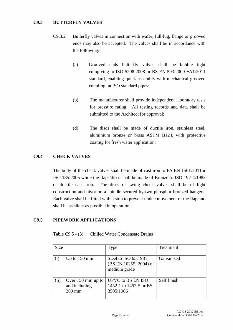
C9.5 PIPEWORK APPLICATIONS
Table C9.5 - (3) Chilled Water Condensate Drains
Size
Type Treatment
(i) Up to 150 mm Steel to ISO 65:1981
(BS EN 10255: 2004) of
medium grade
Galvanised
(ii) Over 150 mm up to
and including
300 mm
UPVC to BS EN ISO
1452-1 to 1452-5 or BS
3505:1986
Self finish

Page 30 of 55
AC_GS 2012 Edition
Corrigendum GSAC02-2012
Note: For pipe sizes of over 300 mm, the requirements, including the pipe
wall thickness, will be fully detailed in the Particular Specification.
Table C9.5 - (5) Condenser Circulation Pipework, Fresh Water passing
through Cooling Tower
Size Type Treatment
(i) Up to 150 mm Steel to ISO 65:1981
(BS EN 10255: 2004) of
medium grade
Galvanised
(ii) Over 150 mm up to
and including
300 mm
UPVC to BS EN ISO
1452-1 to 1452-5 or BS
3505:1986
Self finish
(iii) Over 150 mm up to
and including
300 mm
Ductile iron to
BS EN 545:2010 of
appropriate grade
For screw-on flanges
connection, thickness
grade of Class K12
External Coating:
Metallic zinc covered
by a finishing layer of
bitumen paint
Internal Lining:
Cement Mortar as in
Note 4 below
Note: For pipe sizes of over 300 mm, the requirements, including the pipe
wall thickness, will be fully detailed in the Particular Specification.
Table C9.5 - (6) Condenser Circulation Pipework for Sea Water Treated
Effluent Water and Brackish Well Water (Cooling tower or
once through systems)
Size Type Treatment
(i) Up to 150 mm UPVC to BS EN ISO
1452-1 to 1452-5 or BS
3505:1986
Self finish
(ii) Over 150 mm up to
and including
300 mm
Ductile iron or UPVC as
for fresh water at Table
C9.5 - (5)
As ductile iron
treatment as in Table
C9.5- (5) (iii)
Note: For pipe sizes of over 300 mm, the requirements, including the pipe
wall thickness, will be fully detailed in the Particular Specification.

Page 31 of 55
AC_GS 2012 Edition
Corrigendum GSAC02-2012
Table C9.5 - (7) Cold Water Make-up Supply to Air-conditioning Plant Cold
Feed
Size Type Treatment
(i) Up to 150 mm UPVC to BS 3505: 1986
or BS EN ISO 1452-1 to
1452-5 of
appropriate grade
Self finish
Where copper pipe work is indicated, the tubes shall be of the following types:-
(a) Light gauge copper to BS EN 1057:2006+A1:2010. Refrigeration
copper tubes to BS EN 12735-1 (tubes for piping system) or 12735-2
(tubes for equipment) for refrigerant distribution purpose.
(b) Where buried underground tubes shall be to BS EN 1057:2006; and
(c) Tubes shall be suitably joined by capillary or compression fittings to
ISO 2016:1981 or to BS EN ISO 6708:1996 and ISO 7268: 1983/Amd
1:1984 (BS EN 1254-1 to 1254-4). For jointing screwed copper tubes,
cast copper alloy fittings to ISO 7-1:1994/Cor1:2007 (BS EN 1254-1 to
1254-4) shall be used.
Note 2:- UPVC pipe has several pressure ratings, i.e. appropriate grade for BS
EN ISO 1452-1 to 1452-5 or BS 3505:1986. If pressure ratings are not
indicated in the Drawing or Particular Specification, A/C Contractor
shall provide pipes with pressure ratings equal to twice the actual
working pressure to which the pipes are being subjected.
Note 4:- All pipes and fittings shall be cement mortar lined in accordance with
BS EN 545:2010, BS EN 598:2007+A1:2009, BS EN 969:2009, Type
A - Portland pulverised fuel ash cement (PFAC) in accordance with BS
EN 197-1:2011 with a minimum pulverised fuel ash content of 25%; or
Type B - sulphate resisting cement (SRC).
Note 5:- UPVC pipework to BS 3505:1986 or BS EN ISO 1452 shall be in
accordance with BS EN ISO 1452-1:2009, BS EN ISO 1452-2:2009,
BS EN ISO 1452-3:2010, BS EN ISO1452-4:2009 and BS EN ISO
1452-5:2009.
C9.8 STRAINERS

Page 32 of 55
AC_GS 2012 Edition
Corrigendum GSAC02-2012
Straining cages and their supporting structure shall be of non-ferrous metal or
stainless steel with 1.5 mm diameter perforations or finer if indicated. Cage
shall be at least five times the cross-sectional area of the pipe or Y-type strainer
of appropriate size as approved by the Architect.
SECTION C10
SYSTEM MONITORING INSTRUMENT
C10.4 THERMOMETERS - LIQUID IMMERSION
Thermometers shall be of the mercury or alcohol-in-glass type of at least 150
mm long with accuracy of 0.5ºC.
C10.5 PRESSURE GAUGES FOR WATER SYSTEMS
The dials of gauges shall not be less than 100 mm diameter and the cases shall
be of polished brass or chromium-plated or anti-corrosive painted mild steel
with optical sight glass.
C10.7 ORIFICE PLATE METERING
Where these are to be installed the orifice plates shall be of stainless steel and of
the well established manufacturer’s make with proven performance
characteristics in compliance with ISO 5167-1:2003 or BS 7350:1990. The
resistance across the plant orifice shall not exceed 5 kPa (0.05 bar).
C10.8 ELECTROMAGNETIC AND ULTRASONIC FLOWMETERS
The flowmeter shall conform to BS EN 61000-6-1:2007, BS EN 61000-6-
2:2005, BS EN 61000-6-3:2007+A1:2011 and BS EN 61000-6-4:2007 or similar
international standards on Electro-magnetic Compatibility (EMC) compliance
for industrial and commercial applications.
SECTION C11
THERMAL INSULATION
C11.1 GENERAL

Page 33 of 55
AC_GS 2012 Edition
Corrigendum GSAC02-2012
C11.1.1 Thermal insulation shall comply with the requirements of BS
5422:2009 and BS 5970:2012 or other statutory standards such as IEC,
ISO and etc. or equivalent.
C11.2 TYPES OF THERMAL INSULATION MATERIALS
C11.2.1 Type "A" - CFC & HCFC Free Phenolic Foam Insulation
(d) Thermal Conductivity: 0.022 W/mC at 20C mean
temperature (BS EN ISO 4590:2003 and BS ISO 1922:2012
or ISO 8302:1991);
(e) Closed Cell Content: 90% minimum (BS EN ISO 4590:2003
and BS ISO 1922:2012 or BS EN ISO 4590:2003);
(f) Vapour Transmission: 10 micron gram meter/Nh at 38C
88% RH (BS EN ISO 4590:2003 and BS ISO 1922:2012 or
ISO 1663:2007); and
C11.2.4 Type "D" - Flexible Closed Cell Elastomeric Insulation
(g) Smoke Visibility (ISO 5659-2:2012); and
The mean specific optical density, Dm shall be less than 500
under all test conditions. The thickness of the test specimen
shall be 25 mm and the Dm shall be the maximum value of
the specific optical density (Ds10) of the three tests computed
at 10 minutes time interval.
C11.2.8 Type "H" –Polyurethane Foam Insulation with no ozone depleting
substances
(e) Close cell content : 95% minimum (BS EN ISO
4590:2003 and BS ISO 1922:2012
or BS EN ISO 4590:2003).
C11.4 VAPOUR BARRIERS
C11.4.2 Aluminium foil vapour barriers used for insulation of all pipework
and ductwork shall conform to the following requirements:-

Page 34 of 55
AC_GS 2012 Edition
Corrigendum GSAC02-2012
(d) Water Vapour Permeance (ASTM E96 /E96M-12)
1.0g/Ns; and
C11.4.3 All joints shall be either factory or on job site fabricated. All joints
shall allow for 50 mm overlap of vapour barrier and the joints shall be
completely sealed using foil tape with a minimum width of 75 mm
conforming to the following specifications:-
(b) Machine and Cross Direction Tensile Strength (ASTM
D882-12) 2.0 kN/m;
C11.5 INSULATION THICKNESSES
C11.5.2 Refrigerant Pipe
Table C11.5.2 – (1) : Minimum Insulation Thickness for Indoor Refrigerant
Pipe (Case 1)
Note :
(1) The above table assumes pipes to be copper pipe of BS EN
1057:2006+A1:2010. For other metal pipes, same insulation
thickness is applied to comparable outer diameters.
SECTION C13
WATER HANDLING EQUIPMENT
C13.1 FRESH WATER PUMPS
C13.1.3 Standards
(a) Casing Material
Unless otherwise specified for the above types of pumps,
cast iron shall comply with BS EN 1561:2011 or ISO
185:2005.
(d) Stuffing Boxes and Drain Piping
Cast iron stuffing boxes housing shall comply with BS EN
1561:2011 or ISO 185:2005 and shall be of ample length

Page 35 of 55
AC_GS 2012 Edition
Corrigendum GSAC02-2012
with bronze lined gland and neck bush, fitted with approved
packing and lantern ring water seal. Drain piping to the
nearest builder’s drain to remove gland leakage shall be
provided. Alternatively, a mechanical seal may be offered.
Mechanical seals shall be of leak free operation. The
mechanical seal shall be the product of specialist proprietor
and the materials used shall be suitable for the pumped liquid.
C13.3 SALINE WATER PUMPS
C13.3.3 Standards
(a) Casing
Unless otherwise indicated, the casing shall be of cast iron to
BS EN 1561:2011 or ISO 185:2005 or better and approved.
(b) Impeller and Shaft Sleeve
(ii) Austenitic cast iron to BS EN 13835:2012 Grade F1;
or ISO 2892: 2007/Cor 1:2009; or
C13.5 SUMP PUMP
C13.5.3 General Requirements
Pumps for flammable zones shall be equipped with flameproof submersible
motor in compliance with BS EN 60079-0:2012 and BS EN 60079-1:2007.
C13.12 FLANGED CONNECTIONS
Pumps shall have flanged connections conforming to the Table of BS EN 1515-
1:2000, BS EN 1092-1:2007, BS EN 1092-2:1997, ISO 7005-1:2011 or ISO
7005-2:1988 as appropriate to the maximum working pressure. Taper pieces
shall be provided where necessary for connection to pipe-work.
C13.14 SEA WATER STRAINERS AND TRAVELLING BAND SCREENS
The body of the auto-strainer / band screen shall be of stainless steel AISI 316 or
if approved of cast iron to BS EN 1561:2011 or ISO 185:2005 or ASTM A436

Page 36 of 55
AC_GS 2012 Edition
Corrigendum GSAC02-2012
Grade 1B or ASTM 278 Class 40 construction with BS EN 10095:1999, BS EN
10084:2008 and BS EN 10087:1999, AISI 316 stainless steel lining, housing a
rotating tapered drum attached to a stainless steel shaft of AISI 316 or a
stationary drum. The unit shall be suitable in operation under a pressure of
1034 kPa at 65oC.
C13.15 FEED AND EXPANSION FACILITY
C13.15.2 Types of Cistern and Tank
(d) Connections
Connections to mild steel cisterns and tanks shall be made by
means of bossed, screwed flanges or pads and studs.
Connections on mild steel cisterns shall be welded before
galvanizing. Flanges shall comply with BS EN 1092-1:2007
PN6 to PN40 as appropriate or ISO 7005-1:2011, ISO 7005-
2:1988 and ISO 7005-3:1988.
PART D - INDOOR AIR QUALITY (IAQ)
D.1 GENERAL
- Building (Planning) Regulations, under the Buildings Ordinance
(Cap. 123);
D.5 EQUIPMENT/ MATERIALS – PART C: TREATMENT AND
CONDITIONING MEDIA
D.5.1.1 Specification of Desiccant Type Outdoor Air Pre-conditioner
(d) Total Heat Recovery Wheel
(viii) The wheel shall be independently tested; shall
conform with the requirements of NFPA-90A:2012
and shall have a flame spread less than 25 and a
smoke developed less than 50 when both rated in
accordance with ASTM E84-09c.
(e) Filter

Page 37 of 55
AC_GS 2012 Edition
Corrigendum GSAC02-2012
(ii) The filter shall be listed by Underwriters laboratories
as Class 2 and the filter efficiency shall be 30% to
ANSI/ASHRAE Standard 52.2-2012.
PART G - PAINTING, FINISHING AND PROTECTIVE TREATMENT
G.3 IDENTIFICATION OF PIPELINES
All pipework in the plant/machinery rooms shall be finished generally in
accordance with ISO 3864-1:2011. All pipework, where exposed on surfaces
outside the plant/machinery room, shall be painted either as in the
plant/machinery room or to match the surrounding surface with distinguishing
colour code bands plus flow arrows in the specified colour scheme as directed
by the Architect.
Pipes and pipelines shall be painted in colours either in accordance with ISO
3864-1:2011 or as directed by the Architect completed with the identification
colour code indicators. The basic identification colour or the decoration colour
shall be applied over the whole length of the pipe with colour code indicators
placed at all junctions, at both sides of valves, service appliances, bulkheads,
wall penetrations and at any other places where identification is necessary as
directed by the Architect.
Colour code numbers are those of BS 4800:2011. The schedule of colour for
ready mixed paints and BS colour reference shall be as Clause G.4, in table G.4-
(1) and G.4-(2).
G.4 SCHEDULE OF COLOURS
Colour schedule as stated below are those of BS 4800:2011 for ready mixed
paints.
PART H - INSPECTION, TESTING AND COMMISSIONING
H.4 OFF-SITE TESTS
H.4.1 Fans: "type-tests" Certificates showing fan characteristic curves
(ISO 5801:2007/Cor 1:2008), "type-tests" Certificates for sound
power levels (BS EN ISO 5136:2009), fan dynamic balancing test
Certificates completed with a method of statement from manufacturer
Page 38 of 55
AC_GS 2012 Edition
Corrigendum GSAC02-2012
on testing to Grade 2.5, 4 & 6.3 on appropriate fan types in
accordance with ISO 1940-1:2003 and ISO 21940-14:2012.
H.4.2 Pumps: "type-tests" Certificates for head, discharge, speed and power
input (BS EN ISO 9906:2012 as appropriate).
H.4.3 Electric motors: "type-tests" Certificates in accordance with BS EN
60034-1:2010 and/or IEC 60072-1:1991, IEC 60072-2:1990 &
IEC 60072-3:1994.
H.4.6 Other electrical equipment, such as air heaters (but excluding
thermostatic control equipment): "type-tests" Certificates in
accordance with BS EN 60335-1:2012, BS EN 60669-
1:1999+A2:2008, BS 5733:1995 and BS 6220:1983 as appropriate.
H.4.7 Refrigeration plant: "type-tests" Certificates for hydraulic and air
pressure testing at works in accordance with BS EN 378-1:2008,
BS EN 378-2: 2008+A2:2012, BS EN 378-3:2008+A1:2012 and BS
EN 378-4:2008+A1:2012.
ANNEX I
LIST OF TECHNICAL STANDARDS QUOTED IN THIS GENERAL
SPECIFICATION
Standard Description Part and
Clause No.
ANSI/ASHRAE
15-2010
Safety Standard for Refrigeration Systems B6.1, B6.2,
B6.14.1, C6.1,
C6.21.1
ANSI/ASHRAE
52.1-1992 Gravimetric and Dust Spot Procedures for
Testing Air-Cleaning Devices Used in General
Ventilation for Removing Particulate Matter
C1.2.1(a),D.5.4

Page 39 of 55
AC_GS 2012 Edition
Corrigendum GSAC02-2012
Standard Description Part and
Clause No.
ANSI/ASHRAE
52.2-2012 Method of Testing General Ventilation Air-
Cleaning Devices for Removal Efficiency by
Particle Size
C1.1.1, C1.2.1
(b), C1.3, C1.4,
C1.5, C1.6,
C1.7, C1.8,
C1.9, C1.10,
C1.12, C1.14,
D.5.1.1(e)(ii)
ANSI/ASHRAE
70-2006 Method of Testing the Performance of Air Outlets
and Air Inlets C3.14.1(a),
C3.13.4(b)
ANSI/ASHRAE
84-2008 Method of Testing Air-to-Air Heat Exchangers D.5.1.1(d)(v)
ANSI/ASHRAE
135-2012 BACnet(r): A Data Communication Protocol for
Building Automation and Control Networks B5.1.2(c),
C5.3(a)
ANSI/ASME Code
B31.5: 2010
Refrigeration Piping and Heat Transfer
Components
C6.20.3
ANSI/CEA-709.1-
B:2002
Control Network Protocol Specification C5.3(c)
ANSI/EIA 310-
D:1992
Mechanical Core Specifications for
Microcomputers Using IEC 603-2 Connectors
C5.4(a)
ANSI/IIAR 2-2008 Design, and Installation of Ammonia Mechanical
Refrigerating Systems
B6.14.1,
B6.14.4,
C6.20.3
AHRI 210/240:2008 Performance Rating of Unitary Air-Conditioning
& Air-Source Heat Pump Equipment C6.22.4
AHRI 410:2001 Forced-Circulation Air-Cooling and Air-Heating
Coils C3.6.3(b),
C3.2.10(f),
C3.2.13(c)
AHRI 550/590: 2012 Performance Rating of Water Chilling Packages
Using the Vapor Compression Cycle C6.1
AHRI 575:2008 Method of Measuring Machinery Sound Within
an Equipment Space C6.1
AHRI 1060:2005 Performance Rating of Air-To-Air Heat
Exchangers for Energy Recovery Ventilation
Heat Equipment
D.5.1.1(d)(v)
AS 3498:2009 Authorization requirements for plumbing
products - Water heaters and hot-water storage
tanks
C6.28.4

Page 40 of 55
AC_GS 2012 Edition
Corrigendum GSAC02-2012
Standard Description Part and
Clause No.
AS/NZS 2712:2007 Solar and Heat Pump Water Heaters - Design and
Construction C6.28.3(a)
ASME Boiler and
Pressure Vessel
Code: 2007
2007 ASME Boiler and Pressure Vessel Code,
Section II - Materials B6.14.1,
C6.20.3
ASTM
A278/A278M-
01:2011
Standard Specification for Gray Iron Castings for
Pressure-Containing Parts for Temperatures Up to
650 °F (350 °C)
C13.14
ASTM A436-
84:2011 Standard Specification for Austenitic Gray Iron
Castings C13.14
ASTM
B124/B124M-09 Standard Specification for Copper and Copper
Alloy Forging Rod, Bar, and Shapes C9.3.2(d)
ASTM C423-09a Standard Test Method for Sound Absorption and
Sound Absorption Coefficients by the
Reverberation Room Method
C8.7, C8.12.5
ASTM C916-
85(2007) Standard Specification for Adhesives for Duct
Thermal Insulation B8.7
ASTM C1071-12 Standard Specification for Fibrous Glass Duct
Lining Insulation (Thermal and Sound Absorbing
Material)
C8.7
ASTM
D579/D579M-10 Standard Specification for Greige Woven Glass
Fabrics B11.6.3(c)
Withdrawn C11.4.2(c)
Withdrawn C11.4.2(a) &
(b)
ASTM D882-12 Standard Test Method for Tensile Properties of
Thin Plastic Sheeting C11.4.3(b)
ASTM
D3330/D3330M-
04(2010)
Standard Test Method for Peel Adhesion of
Pressure-Sensitive Tape C11.4.3(c)
ASTM E84-09c Standard Test Method for Surface Burning
Characteristics of Building Materials B11.6.4(d),
C6.13.4, C8.7,
C8.9,
D.5.1.1(d)(viii)
ASTM E90-09 Standard Test Method for Laboratory
Measurement of Airborne Sound Transmission
Loss of Building Partitions and Elements
C8.8, C8.12.5,
C8.10

Page 41 of 55
AC_GS 2012 Edition
Corrigendum GSAC02-2012
Standard Description Part and
Clause No.
ASTM E96/E96M-
12 Standard Test Methods for Water Vapour
Transmission of Materials C11.4.2(d)
ASTM E408-
71:2008 Standard Test Methods for Total Normal
Emittance of Surfaces Using Inspection-Meter
Techniques
C11.2.1(g),
C11.4.2(e),
C11.4.3(e),
C11.5
ASTM G21-09 Standard Practice for Determining Resistance of
Synthetic Polymeric Materials to Fungi C2.6.2
BS 417-2:1987 Specification for galvanized low carbon steel
cisterns, cistern lids, tanks and cylinders. Metric
units
C13.15.2(a)(i)
BS 476-12:1991 Fire tests on building materials and structures.
Method of test for ignitability of products by
direct flame impingement
C2.4,
C3.13.1(d),
C3.14.3(b),
C11.1.2,
C11.1.2(a)
BS 476-20:1987 Fire tests on building materials and structures.
Method for determination of the fire resistance of
elements of construction (general principles)
B2.4, C2.11.1,
C2.11.2, C8.10,
C8.12.2
BS 476-21:1987 Fire tests on building materials and structures.
Methods for determination of the fire resistance
of loadbearing elements of construction
C2.11.1,
C2.11.2, C8.10,
C8.12.2
BS 476-22:1987 Fire tests on building materials and structures.
Methods for determination of the fire resistance
of non-loadbearing elements of construction
B2.4, C2.11.1,
C2.11.2, C8.10,
C8.12.2
BS 476-23:1987 Fire tests on building materials and structures.
Methods for determination of the contribution of
components to the fire resistance of a structure
B2.4, C2.11.1,
C2.11.2
BS 476-4:1970 Fire tests on building materials and structures.
Non-combustibility test for materials
C1.2.2(a), C8.7,
C8.9,
C3.13.1(d),
C3.14.3(b)
BS 476-6:2009
Fire tests on building materials and structures.
Method of test for fire propagation for products
C1.2.2(b),
C2.4, C2.8,
C3.13.1(d),
C3.14.3(b),
C11.1.2,
C11.1.2(b)

Page 42 of 55
AC_GS 2012 Edition
Corrigendum GSAC02-2012
Standard Description Part and
Clause No.
BS 476-7:1997 Fire tests on building materials and structures.
Method of test to determine the classification of
the surface spread of flame of products
B2.4, C1.18,
C2.8, C2.15,
C3.13.1(d),
C3.14.3(b),
C11.1.2,
C11.1.2(c)
BS 1564:1975 Specification for pressed steel sectional
rectangular tanks
C13.15.2(a)(ii)
BS 1710:1984 Specification for identification of pipelines and
services
B11.8.3
BS 3790:2006 Specification for belt drives. Endless wedge belts,
endless V-belts, banded wedge belts, banded V-
belts and their corresponding pulleys
B3.1
BS 3928:1969 Method for sodium flame test for air filters (other
than for air supply to I.C. engines and
compressors)
C3.2.8
BS 4213:2004 Cisterns for domestic use. Cold water storage and
combined feed and expansion (thermoplastic)
cisterns up to 500 l. Specification
C13.15.2(a)(iii)
BS EN ISO
844:2009
Rigid cellular plastics. Determination of
compression properties
C11.2.1(c),
C11.2.8(c)
BS EN ISO
4590:2003
Rigid cellular plastics. Determination of the
volume percentage of open cells and of closed
cells
C11.2.1(d),(e),
(f), C11.2.8(e)
BS ISO 1922:2012 Rigid cellular plastics. Determination of shear
strength
Ditto
BS 4800:2011 Schedule of paint colours for building purposes B11.8.2, G3,
G4
BS 4856-2:1975 Methods for testing and rating fan coil units, unit
heaters and unit coolers. Thermal and volumetric
performance for cooling duties: without
additional ducting
C3.6.1
BS 4857-1:1972 Methods for testing and rating terminal reheat
units for air distribution systems. Thermal and
aerodynamic performance
C3.13.1(a)
BS 4857-2:1978 Methods for testing and rating terminal reheat
units for air distribution systems. Acoustic testing
and rating
C3.13.1(a)

Page 43 of 55
AC_GS 2012 Edition
Corrigendum GSAC02-2012
Standard Description Part and
Clause No.
BS 4954-1:1973 Methods for testing and rating induction units for
air distribution systems. Thermal and
aerodynamic performance
C3.13.1(a)
BS 4954-2:1978 Methods for testing and rating induction units for
air distribution systems. Acoustic testing and
rating
C3.13.1(a)
BS 5141-2:1977 Specification for air heating and cooling coils.
Method of testing for rating of heating coils
C3.2.13(c)
BS 5315:1991 Hose clamps (worm drive type) for general
purpose use (metric series)
B2.5
BS 5422:2009 Method for specifying thermal insulating
materials for pipes, tanks, vessels, ductwork and
equipment operating within the temperature range
-40°C to +700°C
C11.1.1
BS 5733:1995 Specification for general requirements for
electrical accessories
H.4.6
BS 5970:2012 Thermal insulation of pipework, ductwork,
associated equipment and other industrial
installations in the temperature range of -100°C
to +870°C. Code of practice.
C11.1.1
BS 6387:1994 Specification for performance requirements for
cables required to maintain circuit integrity under
fire conditions
C3.1.5
BS 7116:1990 Specification for double sided pressure sensitive
adhesive tapes
C11.4.3(d)
BS ISO 10816-
1:2009
Mechanical vibration. Evaluation of machine
vibration by measurements on non-rotating parts.
General guidelines
C3.1.4(b)
BS EN 197-1:2011 Cement. Composition, specifications and
conformity criteria for common cements
C9.5
BS EN 378-1:2008 Refrigerating systems and heat pumps. Safety and
environmental requirements. Basic requirements,
definitions, classification and selection criteria
H.4.7
BS EN 378-2:
2008+A2:2012
Refrigerating systems and heat pumps. Safety and
environmental requirements. Design,
construction, testing, marking and documentation
B6.2, C6.21.1,
H.4.7

Page 44 of 55
AC_GS 2012 Edition
Corrigendum GSAC02-2012
Standard Description Part and
Clause No.
BS EN 378-
3:2008+A1:2012
Refrigerating systems and heat pumps. Safety and
environmental requirements. Installation site and
personal protection
B6.1, B6.2,
H.4.7
BS EN 378-
4:2008+A1:2012
Refrigerating systems and heat pumps. Safety and
environmental requirements. Operation,
maintenance, repair and recovery
H.4.7
BS EN 545:2010
Ductile iron pipes, fittings, accessories and their
joints for water pipelines. Requirements and test
methods
C9.5
BS EN 598:
2007+A1:2009
Ductile iron pipes, fittings, accessories and their
joints for sewerage applications. Requirements
and test methods
C9.5
BS EN 779:2012 Particulate air filters for general ventilation.
Determination of the filtration performance
C3.2.8,
C3.6.1(b)
BS EN 837-1:1998 Pressure gauges. Bourdon tube pressure gauges.
Dimensions, metrology, requirements and testing
C10.5
BS EN 969:2009 Ductile iron pipes, fittings, accessories and their
joints for gas pipelines. Requirements and test
methods
C9.5
BS EN
1057:2006+A1:2010
Copper and copper alloys. Seamless, round
copper tubes for water and gas in sanitary and
heating applications
C9.5, C11.5.2
BS EN 1092-1:2007 Flanges and their joints. Circular flanges for
pipes, valves, fittings and accessories, PN
designated. Steel flanges
C8.5.2, C13.12,
C13.15.2(d)
BS EN 1092-2:1997 Flanges and their joints. Circular flanges for
pipes, valves, fittings and accessories, PN
designated. Cast iron flanges
C13.12
BS EN 1287:1999 Mixing valves. Specification for thermostatic
mixing valves
C9.9
BS EN 1515-1:2000 Flanges and their joints. Bolting. Selection of
bolting
C13.12
BS EN 1561:2011 Founding. Grey cast irons B9.15.3, C9.4,
C13.1.3(a),
C13.1.3(d),
C13.3.3(a),
C13.14

Page 45 of 55
AC_GS 2012 Edition
Corrigendum GSAC02-2012
Standard Description Part and
Clause No.
BS EN 1751:1999 Ventilation for buildings. Air terminal devices.
Aerodynamic testing of dampers and valves
C2.8, C2.12
BS EN 1822-1:2009 High efficiency air filters (EPA, HEPA and
ULPA). Classification, performance testing,
marking
C1.2.1(e)
BS EN 1822-2:2009 High efficiency air filters (EPA, HEPA and
ULPA). Aerosol production, measuring
equipment, particle counting statistics
C1.2.1(e)
BS EN 1822-3:2009 High efficiency air filters (EPA. HEPA and
ULPA). Testing flat sheet filter media
C1.2.1(e)
BS EN 1822-4:2009 High efficiency air filters (EPA, HEPA and
ULPA). Determining leakage of filter element
(scan method)
C1.2.1(e)
BS EN 1822-5:2009 High efficiency air filters (EPA, HEPA and
ULPA). Determining the efficiency of filter
element
C1.2.1(e)
BS EN 1886:2007 Ventilation for buildings. Air handling units.
Mechanical performance
C3.2.1, C3.2.2,
C3.2.7
BS EN 1982:2008 Copper and copper alloys. Ingots and castings C13.1.3(b),
C13.1.3(c),
C13.3.3(b)(i)
BS EN 10029:2010 Hot-rolled steel plates 3 mm thick or above.
Tolerances on dimensions and shape.
B9.3.2
BS EN 10051:2010
Continuously hot-rolled strip and plate/sheet cut
from wide strip of non-alloy and alloy steels.
Tolerances on dimensions and shape
B9.3.2
BS EN 10084:2008 Case hardening steels. Technical delivery
conditions
C13.1.3(c),
C13.3.3(d),
C13.14
BS EN 10087:1999 Free cutting steels. Technical delivery conditions
for semi-finished products, hot rolled bars and
rods
C13.1.3(c),
C13.3.3(d),
C13.14
BS EN 10095:1999 Heat resisting steels and nickel alloys C8.5.2,
C13.1.3(c),
C13.3.3(b)(iii),
C13.3.3(d),
C13.14
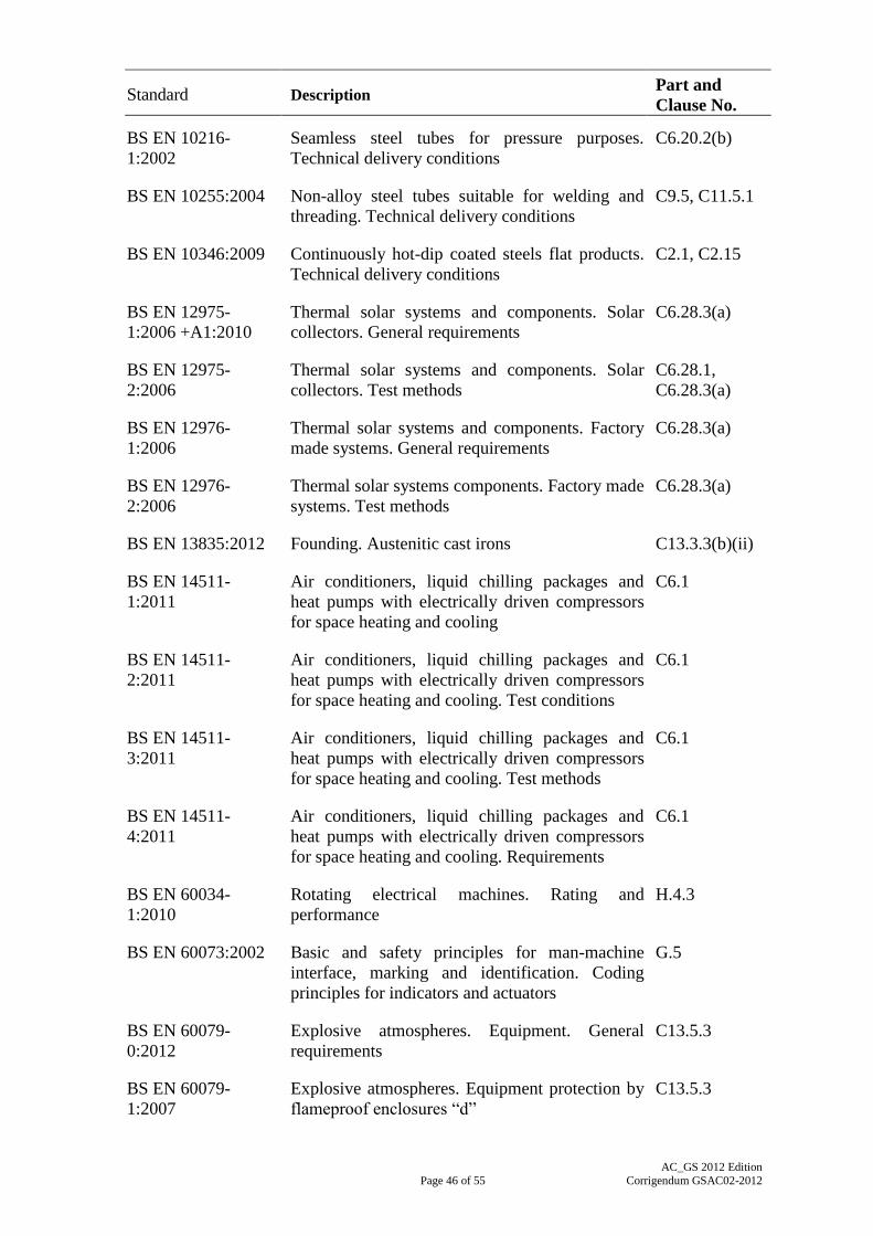
Page 46 of 55
AC_GS 2012 Edition
Corrigendum GSAC02-2012
Standard Description Part and
Clause No.
BS EN 10216-
1:2002
Seamless steel tubes for pressure purposes.
Technical delivery conditions
C6.20.2(b)
BS EN 10255:2004 Non-alloy steel tubes suitable for welding and
threading. Technical delivery conditions
C9.5, C11.5.1
BS EN 10346:2009 Continuously hot-dip coated steels flat products.
Technical delivery conditions
C2.1, C2.15
BS EN 12975-
1:2006 +A1:2010
Thermal solar systems and components. Solar
collectors. General requirements
C6.28.3(a)
BS EN 12975-
2:2006
Thermal solar systems and components. Solar
collectors. Test methods
C6.28.1,
C6.28.3(a)
BS EN 12976-
1:2006
Thermal solar systems and components. Factory
made systems. General requirements
C6.28.3(a)
BS EN 12976-
2:2006
Thermal solar systems components. Factory made
systems. Test methods
C6.28.3(a)
BS EN 13835:2012 Founding. Austenitic cast irons C13.3.3(b)(ii)
BS EN 14511-
1:2011
Air conditioners, liquid chilling packages and
heat pumps with electrically driven compressors
for space heating and cooling
C6.1
BS EN 14511-
2:2011
Air conditioners, liquid chilling packages and
heat pumps with electrically driven compressors
for space heating and cooling. Test conditions
C6.1
BS EN 14511-
3:2011
Air conditioners, liquid chilling packages and
heat pumps with electrically driven compressors
for space heating and cooling. Test methods
C6.1
BS EN 14511-
4:2011
Air conditioners, liquid chilling packages and
heat pumps with electrically driven compressors
for space heating and cooling. Requirements
C6.1
BS EN 60034-
1:2010
Rotating electrical machines. Rating and
performance
H.4.3
BS EN 60073:2002 Basic and safety principles for man-machine
interface, marking and identification. Coding
principles for indicators and actuators
G.5
BS EN 60079-
0:2012
Explosive atmospheres. Equipment. General
requirements
C13.5.3
BS EN 60079-
1:2007
Explosive atmospheres. Equipment protection by
flameproof enclosures “d”
C13.5.3

Page 47 of 55
AC_GS 2012 Edition
Corrigendum GSAC02-2012
Standard Description Part and
Clause No.
BS EN 60335-
1:2012
Household and similar electrical appliances.
Safety. General requirements
H.4.6
IEC 60439-1:2004 Low-voltage switchgear and controlgear
assemblies. Type-tested and partially type-tested
assemblies
H.4.4
BS EN 60529:1992 Specification for degrees of protection provided
by enclosures (IP code)
F.5.3(a)
BS EN 60669-1:
1999+A2:2008
Switches for household and similar fixed
electrical installations. General requirements
H.4.6
BS EN 61000-6-
1:2007
Electromagnetic compatibility (EMC). Generic
standards. Immunity for residential, commercial
and light-industrial environments
C1.16, C10.8
BS EN 61000-6-
2:2005
Electromagnetic compatibility (EMC). Generic
standards. Immunity for industrial environments
C1.16, C10.8
BS EN 61000-6-
3:2007+A1:2011
Electromagnetic compatibility (EMC). Generic
standards. Emission standard for residential,
commercial and light-industrial environments
C1.16, C10.8
BS EN 61000-6-
4:2007
Electromagnetic compatibility (EMC). Generic
standards. Emission standard for industrial
environments
C1.16, C10.8
BS EN ISO 5659-
2:2006
Plastics. Smoke generation. Determination of
optical density by a single-chamber test
C2.7.1.3,
C2.7.2.3,
C11.2.4(g)
BS EN ISO
9001:2008
Quality management systems. Requirements B9.3.2
BS EN ISO
9906:2012
Rotodynamic pumps. Hydraulic performance
acceptance tests. Grades 1 and 2
B13.1, H.4.2
BS PD 5500:2012
Specification for unfired fusion welded pressure
vessels
C6.28.4, C8.5.2
CTI- STD-201:2009 Standard for the Certification of Water Cooling
Tower Thermal Performance
C6.13.1
DIN 50154:1980 Tensile test without extensometer on foils and
strips of aluminium and wrought aluminium
alloys with a thickness up to 0.179 mm
C11.2.8(c), (d)
DIN 53438-3:1984 Testing of combustible materials; response to
ignition by a small flame; surface ignition
C1.2.2(d)

Page 48 of 55
AC_GS 2012 Edition
Corrigendum GSAC02-2012
Standard Description Part and
Clause No.
DW/143:2000 A Practical Guide to Ductwork Leakage Testing B2.1, B2.9,
B2.10, C2.14
DW/144:1998 Specification for Sheet Metal Ductwork Low
Medium & High Pressure Velocity Air Systems C2.3(a), C2.8,
C2.14, C2.15,
C2.17, C3.2.1,
C3.5.1,
C3.13.1(b),
C3.13.4(b),
B2.1, B2.3,
B2.10, B11.8.3
DW/154:2000 Specification for plastics ductwork C2.3(b), C2.5
DW/191:1973 Guide to good practice glass fibre ductwork C2.3(c), C2.6.2
Eurovent Document
2/2 1991
Air Leakage rate in Sheet Metal Air Distribution
Systems
C3.16(c)
IMO MSC 61(67) Smoke and toxicity test C11.2.4(h)
ISO 7-1: 1994/Cor
1:2007
Pipe threads where pressure-tight joints are made
on the threads -- Part 1: Dimensions, tolerances
and designation
B9.8.1, C8.5.2,
B9.3.2, C9.5,
C9.15.3
ISO 65:1981 Carbon steel tubes suitable for screwing in
accordance with ISO 7-1
C9.5
ISO 185:2005 Grey cast irons -- Classification B9.15.3, C9.4,
C13.1.3(a),
C13.1.3(d),
C13.3.3(a),
C13.14
ISO 197-4:1983 Copper and copper alloys -- Terms and
definitions -- Part 4: Castings
C9.4,
C13.1.3(b),
C13.1.3(c),
C13.3.3(b)(i)
ISO 254:2011 Belt drives -- Pulleys -- Quality, finish and
balance
B3.1
BS EN ISO
844:2009
Rigid cellular plastics -- Determination of
compression properties
C11.2.1(c),
C11.2.8(c)
ISO 1081:1995 Belt drives -- V-belts and V-ribbed belts, and
corresponding grooved pulleys -- Vocabulary
B3.1
ISO 1182:2010 Reaction to fire tests for products. Non-
combustibility test
C3.13.1(d),
C3.14.3(b)

Page 49 of 55
AC_GS 2012 Edition
Corrigendum GSAC02-2012
Standard Description Part and
Clause No.
ISO 1663:2007 Rigid cellular plastics -- Determination of water
vapour transmission properties
C11.2.1(f)
ISO 1940-1:2003 Mechanical vibration -- Balance quality
requirements for rotors in a constant (rigid) state -
- Part 1: Specification and verification of balance
tolerances
H.4.1
ISO 21940-14:2012 Mechanical Vibration – Rotor Balancing Part 14:
Procedures for assessing balance errors
H.4.1
ISO 2016:1981 Capillary solder fittings for copper tubes --
Assembly dimensions and tests
B9.9.1, C9.5
ISO 2892: 2007/Cor
1:2009
Austenitic cast irons -- Classification C13.3.3(b)(ii)
ISO 3864-1:2011 Graphical symbols -- Safety colours and safety
signs -- Part 1: Design principles for safety signs
in workplaces and public areas
G.3
ISO 4183:1995 Belt drives -- Classical and narrow V-belts --
Grooved pulleys (system based on datum width)
B3.1
ISO 4184:1992 Belt drives -- Classical and narrow V-belts --
Lengths in datum system
B3.1
BS EN ISO 1452-
1:2009
Plastics piping systems for water supply and for
buried and above – ground drainage and sewerage
under pressure –Unplastized poly (vinyl chloride)
(PVC-U) – Part 1: General
C9.5
BS EN ISO 1452 –
2:2009
Plastics piping systems for water supply and for
buried and above –ground drainage and sewerage
under pressure – Unplastized poly (vinyl
chloride) (PVC-U) – Part 2:Pipes
C9.5
BS EN ISO 1452 –
3:2010
Plastics piping systems for water supply and for
buried and above –ground drainage and sewerage
under pressure – Unplastized poly (vinyl
chloride) (PVC-U) – Part 2:Fittings
C9.5
BS EN ISO 1452 –
4:2009
Plastics piping systems for water supply and for
buried and above –ground drainage and sewerage
under pressure – Unplastized poly (vinyl
chloride) (PVC-U) – Part 4:Valves
C9.5
BS EN ISO 1452 -
5:2009
Plastics piping systems for water supply and for
buried and above –ground drainage and sewerage
under pressure – Unplastized poly (vinyl
chloride) (PVC-U) – Part 5:Fitness
C9.5

Page 50 of 55
AC_GS 2012 Edition
Corrigendum GSAC02-2012
Standard Description Part and
Clause No.
BS EN ISO
4590:2003
Rigid cellular plastics -- Determination of the
volume percentage of open cells and of closed
cells
C11.2.1(e),
C11.2.8(e)
BS EN ISO
5136:2009
Acoustics -- Determination of sound power
radiated into a duct by fans and other air-moving
devices -- In-duct method
H.4.1
ISO 5149:1993 Mechanical refrigerating systems used for cooling
and heating -- Safety requirements
C6.1
ISO 5151:2010 Non-ducted air conditioners and heat pumps --
Testing and rating for performance
B12.1.2
ISO 5167-1:2003 Measurement of fluid flow by means of pressure
differential devices inserted in circular cross-
section conduits running full -- Part 1: General
principles and requirements
C10.7
ISO 5187:1985 Welding and allied processes -- Assemblies made
with soft solders and brazing filler metals --
Mechanical test methods
B9.18.5
ISO 5208:2008 Industrial valves -- Pressure testing of valves C9.3.2.(a)
ISO 5209:1977 General purpose industrial valves -- Marking C9.3.2.(h)
Withdrawn C3.13.1(a)
Withdrawn Air distribution and air diffusion -- Aerodynamic
testing and rating of constant and variable dual or
single duct boxes and single duct units
C3.13.1(a)
Withdrawn C3.13.1(a)
ISO 5292:1995 Belt drives -- V-belts and V-ribbed belts --
Calculation of power ratings
B3.1
ISO 5457:1999/
Amd 1: 2010
Technical product documentation -- Sizes and
layout of drawing sheets
A4.3.2, A4.2.2
BS EN ISO 5659-
2:2012
Plastics -- Smoke generation -- Part 2:
Determination of optical density by a single-
chamber test
C2.7.1.3,
C2.7.2.3,
C11.2.4(g)
ISO 5801: 2007/Cor
1:2008
Industrial fans -- Performance testing using
standardized airways
H.4.1
ISO 6453:1985 Polymeric materials, cellular flexible --
Polyvinylchloride foam sheeting -- Specification
C2.5

Page 51 of 55
AC_GS 2012 Edition
Corrigendum GSAC02-2012
Standard Description Part and
Clause No.
BS EN ISO
6708:1996
Pipework components -- Definition and selection
of DN (nominal size)
C9.5
ISO 7005-1:2011 Pipe flanges -- Part 1: Steel flanges for industrial
and general service piping systems
B9.3.2, B9.3.3,
B9.8.2, B9.9.1,
B9.15.3,
C13.12,
C13.15.2.(d)
ISO 7005-2:1988 Metallic flanges -- Part 2: Cast iron flanges C9.7, C13.12,
C13.15.2.(d)
ISO 7005-3:1988 Metallic flanges -- Part 3: Copper alloy and
composite flanges
C9.7,
C13.15.2.(d)
ISO 7268:
1983/Amd 1:1984
Pipe components -- Definition of nominal
pressure
C9.5
ISO 8079:1984 Aerospace process -- Anodic treatment of
aluminium alloys -- Sulfuric acid process, dyed
coating
C11.2.8(a)
ISO 8302:1991 Thermal insulation -- Determination of steady-
state thermal resistance and related properties --
Guarded hot plate apparatus
C11.2.1(d)
ISO 9001:2008 Quality Management systems -- Requirements A3.15.7,
B9.3.2, C3.2.1,
C3.6.1,
D.5.1.2(a)
ISO 9330-1:1990 Welded steel tubes for pressure purposes --
Technical delivery conditions -- Part 1:
Unalloyed steel tubes with specified room
temperature properties
C9.5
ISO 9330-2:1997 Welded steel tubes for pressure purposes --
Technical delivery conditions -- Part 2: Electric
resistance and induction welded unalloyed and
alloyed steel tubes with specified elevated
temperature properties
C9.5
ISO 9330-3:1997 Welded steel tubes for pressure purposes --
Technical delivery conditions -- Part 3: Electric
resistance and induction welded unalloyed and
alloyed steel tubes with specified low temperature
properties
C9.5
ISO 9461:1992 Hydraulic fluid power -- Identification of valve
ports, subplates, control devices and solenoids
B9.15.3

Page 52 of 55
AC_GS 2012 Edition
Corrigendum GSAC02-2012
Standard Description Part and
Clause No.
ISO 9692-1:2003 Welding and allied processes --
Recommendations for joint preparation -- Part 1:
Manual metal-arc welding, gas-shielded metal-arc
welding, gas welding, TIG welding and beam
welding of steels
B2.7, B9.3.3,
B9.18.3,
B9.18.4
ISO 10294-1:1996 Fire resistance tests -- Fire dampers for air
distribution systems -- Part 1: Test method
C2.11.1,
C2.11.2
ISO 10816-1:
1995/Amd 1:2009
Mechanical vibration -- Evaluation of machine
vibration by measurements on non-rotating parts -
- Part 1: General guidelines
C3.1.4(b)
ISO 13253: 2011 Ducted air-conditioners and air-to-air heat pumps
-- Testing and rating for performance
B12.1.2
ISO 13256-1:1998 Water-source heat pumps -- Testing and rating for
performance -- Part 1: Water-to-air and brine-to-
air heat pumps
B12.1.2
ISO 13256-2:1998 Water-source heat pumps -- Testing and rating for
performance -- Part 2: Water-to-water and brine-
to-water heat pumps
B12.1.2
ISO 13261-1:1998 Sound power rating of air-conditioning and air-
source heat pump equipment -- Part 1: Non-
ducted outdoor equipment
B12.2
ISO 13261-2:1998 Sound power rating of air-conditioning and air-
source heat pump equipment -- Part 2: Non-
ducted indoor equipment
B12.2
ISO 14644-1:1999 Cleanrooms and associated controlled
environments -- Part 1: Classification of air
cleanliness
C1.11
ISO 15609-1:2004 Specification and qualification of welding
procedures for metallic materials welding
procedure specification - Part 1: Arc welding
B9.18.3
ISO 15609-2:2001 Specification and qualification of welding
procedures for metallic materials welding
procedure specification - Part 2: Gas welding
B9.18.4
ISO 1813:1998 Belt drives -- V-ribbed belts, joined V-belts and
V-belts including wide section belts and
hexagonal belts -- Electrical conductivity of
antistatic belts: Characteristics and methods of
test
B3.1

Page 53 of 55
AC_GS 2012 Edition
Corrigendum GSAC02-2012
Standard Description Part and
Clause No.
ISO/IEC 1989: 2002/
Cor 3:2009
Information technology -- Programming
languages -- COBOL
B5.1.2(i),
C5.3(h)
ISO/IEC 8802-
3:2000
Information technology -- Telecommunications
and information exchange between systems --
Local and metropolitan area networks -- Specific
requirements -- Part 3: Carrier sense multiple
access with collision detection (CSMA/CD)
access method and physical layer specifications
B5.1.2(j),
C5.3(i), C5.5
ISO/IEC 9075-
10:2008
Information technology -- Database languages --
SQL -- Part 10: Object Language Bindings
(SQL/OLB)
B5.1.2(a)
ISO/IEC 9075-
13:2008
Information technology -- Database languages --
SQL -- Part 13: SQL Routines and Types Using
the Java TM Programming Language (SQL/JRT)
B5.1.2(a)
ISO/IEC 9075-
9:2008
Information technology -- Database languages --
SQL -- Part 9: Management of External Data
(SQL/MED)
B5.1.2(a),
C5.3(b), C5.13
ISO/TR 5658-1:2006 Reaction to fire tests -- Spread of flame -- Part 1:
Guidance on flame spread
C3.13.1(d),
C3.14.3(b)
NAIMA Publication
AH-122 Cleaning Fibrous Glass Insulated Duct Systems -
Recommended Practices C2.6.2
(NES) 713 (Issue 3) Determination of the Toxicity Index of the
Products of Combustion from Small Specimens
of Material
C11.2.4(h)
NFPA-90A:2012 Standard for the Installation of Air-Conditioning
and Ventilating Systems B11.5.4,
B11.6.4(d),
C2.6.2,
C2.11.1,
C3.13.1(d),
C3.14.3.(b),
D5.1.1(d)(viii)
NFPA-90B:2012 Standard for the Installation of Warm Air Heating
and Air-Conditioning Systems C2.6.2
NFPA 220:2012 Standard on Types of Building Construction B11.6.4(d)
NFPA 255:2006 Standard Method of Test of Surface Burning
Characteristics of Building Materials C8.7, C8.9

Page 54 of 55
AC_GS 2012 Edition
Corrigendum GSAC02-2012
Standard Description Part and
Clause No.
PD 5500:2012 Specification for unfired fusion welded pressure
vessels C6.28.4,
B8.5.5,
C8.5.2
TIA/EIA 232-F Interface Between Data Terminal Equipment and
Data Circuit-Terminating Equipment Employing
Serial Binary Data Interchange
B5.1.2(e), B5.3,
C5.3(d), C5.5
TIA/EIA 485-A
(March 2003)
Electrical Characteristics of Generators and
Receivers for Use in Balanced Digital Multipoint
Systems
B5.1.2(f), B5.3
TIA/EIA 568-C.1
(February 2009)
Commercial Building telecommunications
Cabling Standard B5.1.2(g),
B5.3, C5.3(f)
UL 153:2009 Standard for Portable Electric Luminaires C1.17
UL 181:2005 Factory-Made Air Ducts and Air Connectors C2.6.2,
C3.13.1(d),
C3.14.3(b)
UL 555S:2002 Smoke Dampers C2.11.2
UL 586:2009 High-Efficiency, Particulate, Air Filter Units C1.2.1(c),
C1.11, C1.13
UL 710:2012 Exhaust Hoods for Commercial Cooking
Equipment C1.14
UL 723:2008 Test for Surface Burning Characteristics of
Building Materials C8.7, C8.9
UL 867:2012 Electrostatic Air Cleaners C1.14, C1.16
UL 900:2004 Air Filter Units C1.2.2(c)
UL 1598:2008 Luminaires C1.17
UL 1995:2011 Heating and Cooling Equipment C1.17
Year Title of Codes of Practice/Guideline Part and
Clause No.
2012 Codes of Practice for Minimum Fire Service
Installations and Equipment and Inspection, Testing
and Maintenance of Installations and Equipment
A2.1.2(d)
2009 Code of Practice for the Electricity (Wiring)
Regulations
A2.1.2(c),
A3.15.4
2012 Code of Practice for Energy Efficiency of Building A2.1.2(f),

Page 55 of 55
AC_GS 2012 Edition
Corrigendum GSAC02-2012
Services Installation B2.10,
C3.15(a), E.1,
E.2, E.3
2012 Code of Practice for Prevention of Legionnaires'
Disease issued by Prevention of Legionnaires' Disease
Committee, the Government of HKSAR
A2.1.2(j), F.1
2006 Code of Practice for Water-cooled Air Conditioning
Systems
F.1
2005 Code of Practice on the Handling, Transportation and
Disposal of Asbestos Waste
A2.1.2(o)
2005 Code of Practice on the Packaging, Labelling and
Storage of Chemical Wastes
A2.1.2(p)
2008 Design Manual Barrier Free Access 2008 A2.1.2(i)
2010 Fresh Water Cooling Towers Scheme for Air
Conditioning Systems (FWCT Scheme) published by
the EMSD.
A2.1.2 (a)
2006 Code of Practice for Water-cooled Air Conditioning
Systems published by the EMSD. A2.1.2 (b)
Recommended