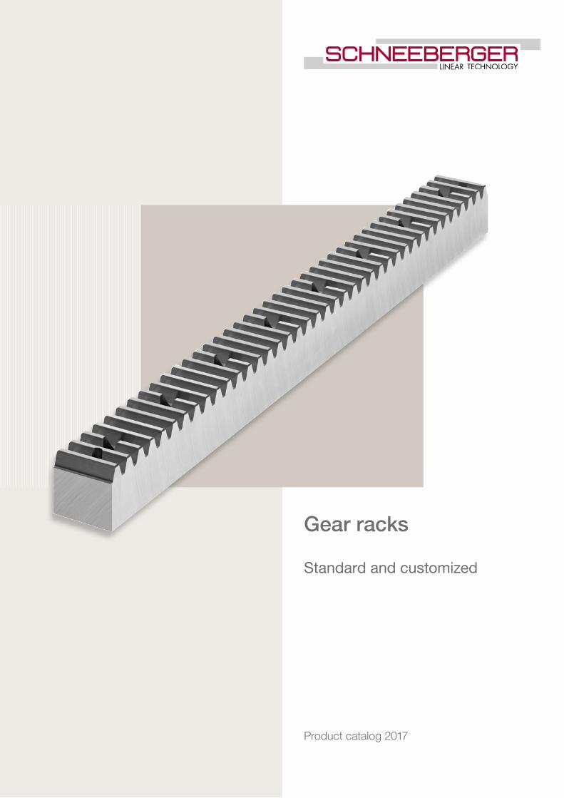
Gear racks
Standard and customized
Product catalog 2017

DisclaimerThis publication has been compiled with great care and all information has been checked for accuracy. However, we can assume no liability for incorrect or incomplete information. We reserve the right to make changes to the information and technical data as a result of enhancements to our products. Reprinting or reproducing, even in part, is not permitted without our written consent.
Latest version of the catalogsYou can always find the latest version of our catalogs in the Download area of our website.
3
1
2
3
4
5
Tab
le o
f co
nten
ts
Overview 4
1.1 Range of versions 41.2 Properties of the gear racks/ conversion 51.3 Conversion/ hardness/ strength 61.4 Fields of application 7
Technical principles 8
Standard gear rack 82.1 Module pitches Q5 - Q11, helical toothed 82.2 Module pitches Q5 - Q11, straight toothed 152.3 Q6 metric pitch, straight toothed 222.4 Q6 stainless steel, helical toothed metric pitch 232.5 Q6 stainless steel straight toothed module pitch 242.6 Q6 stainless steel, straight toothed, metric pitch 25Customised gear racks 262.7 Customised gear racks 26
Installation 27
3.1 Gear rack fitting instructions / lubrication 27
Order description 28
4.1 Standard gear racks 284.2 Customised gear racks 29
Quality 30
5.1 Quality 30
Page number
Table of contents
4
1.1
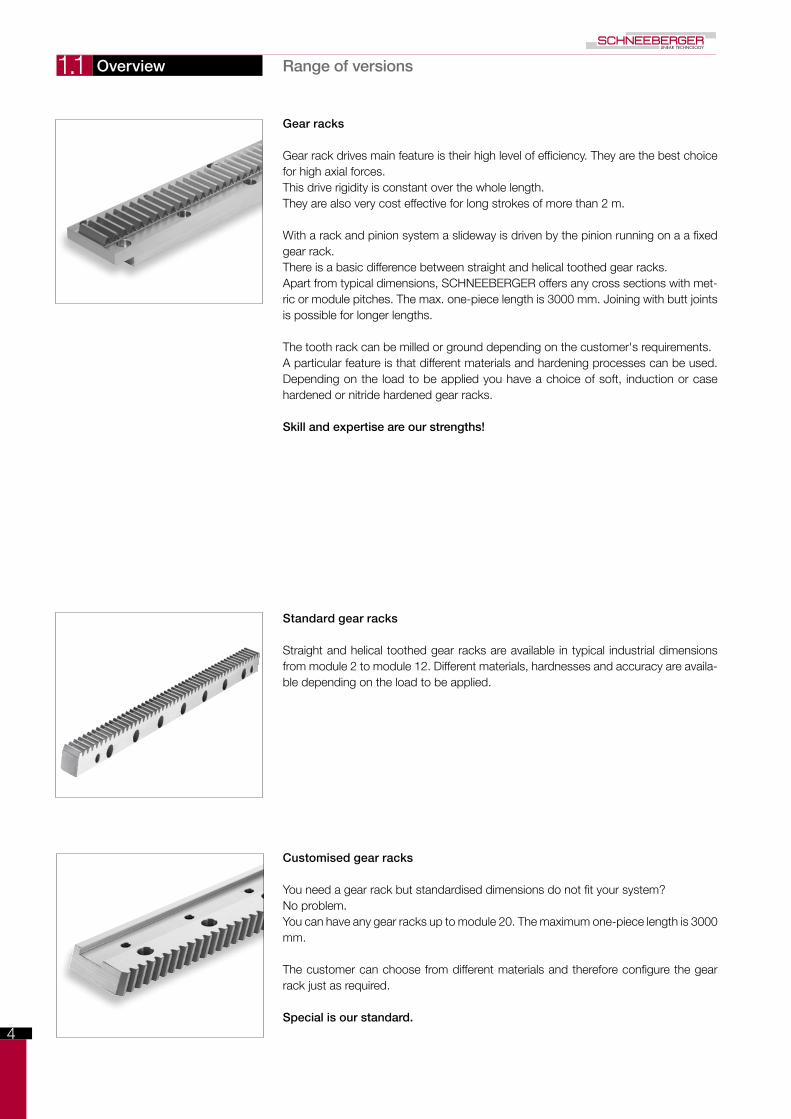
Gear racks
Gear rack drives main feature is their high level of efficiency. They are the best choice for high axial forces. This drive rigidity is constant over the whole length.They are also very cost effective for long strokes of more than 2 m.
With a rack and pinion system a slideway is driven by the pinion running on a a fixed gear rack. There is a basic difference between straight and helical toothed gear racks.Apart from typical dimensions, SCHNEEBERGER offers any cross sections with met-ric or module pitches. The max. one-piece length is 3000 mm. Joining with butt joints is possible for longer lengths.
The tooth rack can be milled or ground depending on the customer's requirements.A particular feature is that different materials and hardening processes can be used. Depending on the load to be applied you have a choice of soft, induction or case hardened or nitride hardened gear racks.
Skill and expertise are our strengths!
Standard gear racks
Straight and helical toothed gear racks are available in typical industrial dimensions from module 2 to module 12. Different materials, hardnesses and accuracy are availa-ble depending on the load to be applied.
Customised gear racks
You need a gear rack but standardised dimensions do not fit your system?No problem.You can have any gear racks up to module 20. The maximum one-piece length is 3000 mm.
The customer can choose from different materials and therefore configure the gear rack just as required.
Special is our standard.
Overview Range of versions
5
1.2
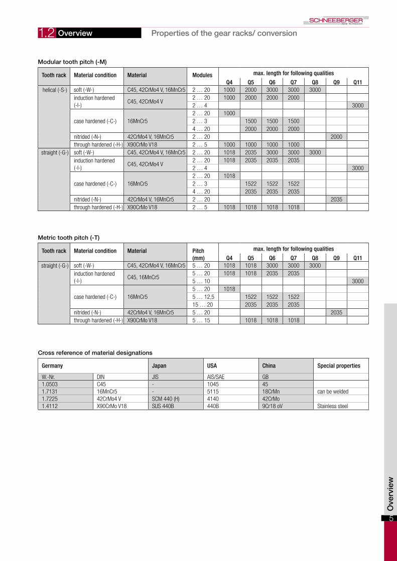
Modular tooth pitch (-M)
Tooth rack Material condition Material Modules max. length for following qualities
Q4 Q5 Q6 Q7 Q8 Q9 Q11helical (-S-) soft (-W-) C45, 42CrMo4 V, 16MnCr5 2 … 20 1000 2000 3000 3000 3000
induction hardened (-I-)
C45, 42CrMo4 V2 … 20 1000 2000 2000 20002 … 4 3000
case hardened (-C-) 16MnCr52 … 20 10002 … 3 1500 1500 15004 … 20 2000 2000 2000
nitrided (-N-) 42CrMo4 V, 16MnCr5 2 … 20 2000through hardened (-H-) X90CrMo V18 2 … 5 1000 1000 1000 1000
straight (-G-) soft (-W-) C45, 42CrMo4 V, 16MnCr5 2 … 20 1018 2035 3000 3000 3000induction hardened (-I-)
C45, 42CrMo4 V2 … 20 1018 2035 2035 20352 … 4 3000
case hardened (-C-) 16MnCr52 … 20 10182 … 3 1522 1522 15224 … 20 2035 2035 2035
nitrided (-N-) 42CrMo4 V, 16MnCr5 2 … 20 2035through hardened (-H-) X90CrMo V18 2 … 5 1018 1018 1018 1018
Ove
rvie
w
Cross reference of material designations
Germany Japan USA China Special properties
W.-Nr. DIN JIS AIS/SAE GB1.0503 C45 - 1045 451.7131 16MnCr5 - 5115 18CrMn can be welded1.7225 42CrMo4 V SCM 440 (H) 4140 42CrMo1.4112 X90CrMo V18 SUS 440B 440B 9Cr18 oV Stainless steel
Metric tooth pitch (-T)
Tooth rack Material condition Material Pitch(mm)
max. length for following qualities
Q4 Q5 Q6 Q7 Q8 Q9 Q11straight (-G-) soft (-W-) C45, 42CrMo4 V, 16MnCr5 5 … 20 1018 1018 3000 3000 3000
induction hardened (-I-)
C45, 16MnCr55 … 20 1018 1018 2035 20355 … 10 3000
case hardened (-C-) 16MnCr55 … 20 10185 … 12,5 1522 1522 152215 … 20 2035 2035 2035
nitrided (-N-) 42CrMo4 V, 16MnCr5 5 … 20 2035through hardened (-H-) X90CrMo V18 5 … 15 1018 1018 1018
Overview Properties of the gear racks/ conversion
6
1.3 Overview Conversion/ hardness/ strength
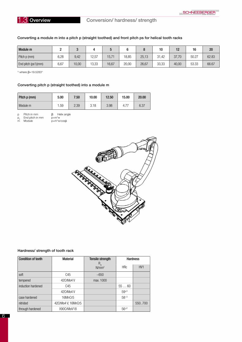
Converting a module m into a pitch p (straight toothed) and front pitch ps for helical tooth racks
Module m 2 3 4 5 6 8 10 12 16 20
Pitch p (mm) 6,28 9,42 12,57 15,71 18,85 25,13 31,42 37,70 50.27 62.83
End pitch (ps1)(mm) 6,67 10,00 13,33 16,67 20,00 26,67 33,33 40,00 53.33 66.67
1) where β=19.5283°
Converting pitch p (straight toothed) into a module m
Pitch p (mm) 5.00 7.50 10.00 12.50 15.00 20.00
Module m 1.59 2.39 3.18 3.98 4.77 6.37
p Pitch in mm β Helix angleps End pitch in mm p=m*πm Module p=m*π/cosβ
Hardness/ strength of tooth rack
Condition of teeth Material Tensile strengthRm
N/mm2
Hardness
HRc HV1
soft C45 ~650
tempered 42CrMo4 V max. 1000
induction hardened C45 55 … 60
42CrMo4 V 59±3
case hardened 16MnCr5 58+3
nitrided 42CrMo4 V, 16MnCr5 550..700
through hardened X90CrMoV18 56±2

7
1.4
Typical applications
Gear racks provides users with definite competitive advantages in the following industries:
• Machine tools• Heavy machine construction• Automation and robotics• Material handling and material flow systems• Machine and plant engineering• Packaging machines• Printing presses
Overview Fields of application
CUSTOMER-SPECIFIC BEARINGS AND GEAR RACKS
Exploring new shores. When research vessels investigate climatechange in the Antarctic, Schneeberger hasalready played its part in the expedition.
Our linear motion technology ma-kes an important contribution in the construction of large ships and their drive systems in particular. Gigan-tic crankshafts and driveshafts are turned, milled, ground and repaired on large, multipurpose extended-bed lathes – with exacting tolerances despite a 40 metre stroke. When our customers approach us about appli-cations such as this, we respond with custom bearings and gear racks. We also supply components for use in electricity generation, for example in the manufacturing of rotor heads or gears for wind turbines. This means we can make our own contribution to exploiting new sources of energy. Our custom bearings and gear racks can be used in any application
where standard bearings do not meet the machine builder’s requirements due to size or accuracy. The results are customer-specific, innovative solutions. We can create guideways with running characteristics, with excee-dingly high rigidity or with extremely high load carrying capacities. When you come to Schneeberger, you do not have to accept any compromi-ses. Our universal machine pool and highly competent engineers allow us to respond to complex customer de-mands for products both quickly and efficiently. Initially in small batches for prototype requirements, and then in larger series volumes, guaranteeing consistently high quality and a reliab-le, secure source of supply.

8
2.1
Tooth rack: Pressure angle α = 20º Quality: 4 in accordance with DIN 3962, 3963, 3967 ground, soft or hardened fp (mm) Single pitch deviationOuter surfaces: groundonallsides Module≤3:0.003 Module > 3: 0.0804 Fp (mm) Total pitch deviation Fp/1000 (mm) 0,015 for a 1000 mm Length
Standard lengthsm 1) p
s 4) L
1L
2z 2) b h
kh
of a l n 3) h d
1d
2t a
1l1
d3
Dimensions
- mm mm mm - mm mm mm mm mm mm - mm mm mm mm mm mm mm kg
ZST M2 - 24 x 24 x 1000 - S 2 6.67 1000.0 8.5 150 24 24 22 2 62.5 125.00 8 8 7 11 7 31.7 936.6 5.7 4.1ZST M2 - 24 x 24 x 2000 - S 2 6.67 2000.0 8.5 300 24 24 22 2 62.5 125.00 16 8 7 11 7 31.7 1936.6 5.7 8.2MST M2 - 24 x 24 x 200 -SL 2 6.67 200.0 8.5 30 24 24 22 0.8
ZST M3 - 29 x 29 x 1000 - S 3 10.00 1000.0 10.3 100 29 29 26 2 62.5 125.00 8 9 10 15 9 35.0 930.0 7.7 5.9ZST M3 - 29 x 29 x 2000 - S 3 10.00 2000.0 10.3 200 29 29 26 2 62.5 125.00 16 9 10 15 9 35.0 1930.0 7.7 11.8MST M3 - 29 x 29 x 200 -SL 3 10.00 200.0 10.3 20 29 29 26 1.2
ZST M4 - 39 x 39 x 1000 - S 4 13.33 1000.0 13.8 75 39 39 35 3 62.5 125.00 8 12 10 15 9 33.3 933.4 7.7 10.7ZST M4 - 39 x 39 x 2000 - S 4 13.33 2000.0 13.8 150 39 39 35 3 62.5 125.00 16 12 10 15 9 33.3 1933.4 7.7 21.4MST M4 - 39 x 39 x 200 -SL 4 13.33 200.0 13.8 15 39 39 35 2.2
ZST M5 - 49 x 39 x 1000 - S 5 16.67 1000.0 17.4 60 49 39 34 3 62.5 125.00 8 12 14 20 13 37.5 925.0 11.7 13.0ZST M5 - 49 x 39 x 2000 - S 5 16.67 2000.0 17.4 120 49 39 34 3 62.5 125.00 16 12 14 20 13 37.5 1925.0 11.7 26.0MST M5 - 49 x 39 x 200 -SL 5 16.67 200.0 17.4 12 49 39 34 2.7
ZST M6 - 59 x 49 x 1000 - S 6 20.00 1000.0 20.9 50 59 49 43 3 62.5 125.00 8 16 18 26 17 37.5 925.0 15.7 18.1ZST M6 - 59 x 49 x 2000 - S 6 20.00 2000.0 20.9 100 59 49 43 3 62.5 125.00 16 16 18 26 17 37.5 1925.0 15.7 36.2MST M6 - 59 x 49 x 200 -SL 6 20.00 200.0 20.9 10 59 49 43 3.8
ZST M8 - 79 x 79 x 960 - S 8 26.67 960.0 28.0 36 79 79 71 3 60.0 120.00 8 25 22 33 21 120.0 720.0 19.7 42.5ZST M8 - 79 x 79 x 1920 - S 8 26.67 1920.0 28.0 72 79 79 71 3 60.0 120.00 16 25 22 33 21 120.0 1680.0 19.7 85.0MST M8 - 79 x 79 x 213 -SL 8 26.67 213.3 28.0 8 79 79 71 8.9
ZST M10- 99 x 99 x 1000 - S 10 33.33 1000.0 35.1 30 99 99 89 3 62.5 125.00 8 32 33 48 32 125.0 750.0 19.7 68.7MST M10- 79 x 79 x 233 -SL 10 33.33 233.3 28.0 7 79 79 69 10.2
ZST M12-120 x 120 x 1000 - S 12 40.00 1000.0 42.6 25 120 120 108 3 40.0 125.00 8 40 39 58 38 125.0 750.0 19.7 111.0MST M12- 99 x 99 x 280 -SL 12 40.00 280.0 35.1 7 99 99 87 20.9
any other lengths on request
1) m Module 3) n Number of holes2) z Number of teeth 4) p
sEnd pitch (p
s=m*π/cos β) β = 19.5283° (19°31’42”)
Technical principles Module pitches helical toothedStandard gear rack Q4
Fig. 1
Fig. 2
Fig. 3
9
2.1
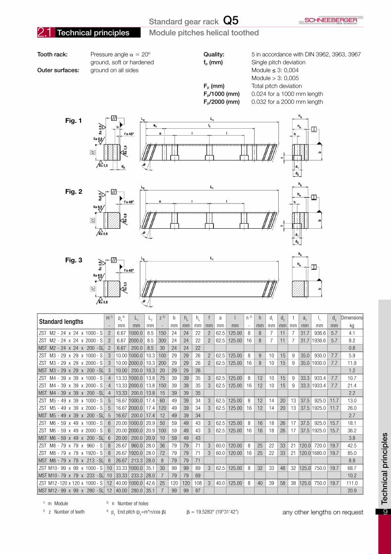
Tooth rack: Pressure angle α = 20º Quality: 5 in accordance with DIN 3962, 3963, 3967 ground, soft or hardened fp (mm) Single pitch deviationOuter surfaces: groundonallsides Module≤3:0,004 Module > 3: 0,005 Fp (mm) Total pitch deviation Fp/1000 (mm) 0.024 for a 1000 mm length Fp/2000 (mm) 0.032 for a 2000 mm length
Fig. 1
Fig. 2
Fig. 3
Standard lengthsm 1) p
s 4) L
1L
2z 2) b h
kh
of a l n 3) h d
1d
2t a
1l1
d3
Dimensions
- mm mm mm - mm mm mm mm mm mm - mm mm mm mm mm mm mm kg
ZST M2 - 24 x 24 x 1000 - S 2 6.67 1000.0 8.5 150 24 24 22 2 62.5 125.00 8 8 7 11 7 31.7 936.6 5.7 4.1ZST M2 - 24 x 24 x 2000 - S 2 6.67 2000.0 8.5 300 24 24 22 2 62.5 125.00 16 8 7 11 7 31.7 1936.6 5.7 8.2MST M2 - 24 x 24 x 200 -SL 2 6.67 200.0 8.5 30 24 24 22 0.8
ZST M3 - 29 x 29 x 1000 - S 3 10.00 1000.0 10.3 100 29 29 26 2 62.5 125.00 8 9 10 15 9 35.0 930.0 7.7 5.9ZST M3 - 29 x 29 x 2000 - S 3 10.00 2000.0 10.3 200 29 29 26 2 62.5 125.00 16 9 10 15 9 35.0 1930.0 7.7 11.8MST M3 - 29 x 29 x 200 -SL 3 10.00 200.0 10.3 20 29 29 26 1.2
ZST M4 - 39 x 39 x 1000 - S 4 13.33 1000.0 13.8 75 39 39 35 3 62.5 125.00 8 12 10 15 9 33.3 933.4 7.7 10.7ZST M4 - 39 x 39 x 2000 - S 4 13.33 2000.0 13.8 150 39 39 35 3 62.5 125.00 16 12 10 15 9 33.3 1933.4 7.7 21.4MST M4 - 39 x 39 x 200 -SL 4 13.33 200.0 13.8 15 39 39 35 2.2
ZST M5 - 49 x 39 x 1000 - S 5 16.67 1000.0 17.4 60 49 39 34 3 62.5 125.00 8 12 14 20 13 37.5 925.0 11.7 13.0ZST M5 - 49 x 39 x 2000 - S 5 16.67 2000.0 17.4 120 49 39 34 3 62.5 125.00 16 12 14 20 13 37.5 1925.0 11.7 26.0MST M5 - 49 x 39 x 200 -SL 5 16.67 200.0 17.4 12 49 39 34 2.7
ZST M6 - 59 x 49 x 1000 - S 6 20.00 1000.0 20.9 50 59 49 43 3 62.5 125.00 8 16 18 26 17 37.5 925.0 15.7 18.1ZST M6 - 59 x 49 x 2000 - S 6 20.00 2000.0 20.9 100 59 49 43 3 62.5 125.00 16 16 18 26 17 37.5 1925.0 15.7 36.2MST M6 - 59 x 49 x 200 -SL 6 20.00 200.0 20.9 10 59 49 43 3.8
ZST M8 - 79 x 79 x 960 - S 8 26.67 960.0 28.0 36 79 79 71 3 60.0 120.00 8 25 22 33 21 120.0 720.0 19.7 42.5ZST M8 - 79 x 79 x 1920 - S 8 26.67 1920.0 28.0 72 79 79 71 3 60.0 120.00 16 25 22 33 21 120.0 1680.0 19.7 85.0MST M8 - 79 x 79 x 213 -SL 8 26.67 213.3 28.0 8 79 79 71 8.9
ZST M10- 99 x 99 x 1000 - S 10 33.33 1000.0 35.1 30 99 99 89 3 62.5 125.00 8 32 33 48 32 125.0 750.0 19.7 68.7MST M10- 79 x 79 x 233 -SL 10 33.33 233.3 28.0 7 79 79 69 10.2
ZST M12-120 x 120 x 1000 - S 12 40.00 1000.0 42.6 25 120 120 108 3 40.0 125.00 8 40 39 58 38 125.0 750.0 19.7 111.0MST M12- 99 x 99 x 280 -SL 12 40.00 280.0 35.1 7 99 99 87 20.9
any other lengths on request
1) m Module 3) n Number of holes2) z Number of teeth 4) p
sEnd pitch (p
s=m*π/cos β) β = 19.5283° (19°31’42”)
Technical principles Module pitches helical toothedStandard gear rack Q5
Tech
nica
l pri
ncip
les
10
2.1
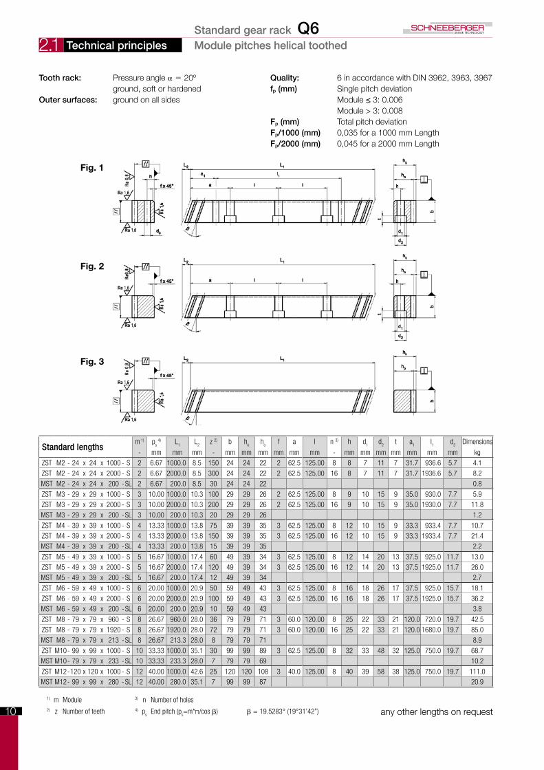
Tooth rack: Pressure angle α = 20º Quality: 6 in accordance with DIN 3962, 3963, 3967 ground, soft or hardened fp (mm) Single pitch deviationOuter surfaces: groundonallsides Module≤3:0.006 Module > 3: 0.008 Fp (mm) Total pitch deviation Fp/1000 (mm) 0,035 for a 1000 mm Length Fp/2000 (mm) 0,045 for a 2000 mm Length
Fig. 1
Fig. 2
Fig. 3
Standard lengthsm 1) p
s 4) L
1L
2z 2) b h
kh
of a l n 3) h d
1d
2t a
1l1
d3
Dimensions
- mm mm mm - mm mm mm mm mm mm - mm mm mm mm mm mm mm kg
ZST M2 - 24 x 24 x 1000 - S 2 6.67 1000.0 8.5 150 24 24 22 2 62.5 125.00 8 8 7 11 7 31.7 936.6 5.7 4.1ZST M2 - 24 x 24 x 2000 - S 2 6.67 2000.0 8.5 300 24 24 22 2 62.5 125.00 16 8 7 11 7 31.7 1936.6 5.7 8.2MST M2 - 24 x 24 x 200 -SL 2 6.67 200.0 8.5 30 24 24 22 0.8
ZST M3 - 29 x 29 x 1000 - S 3 10.00 1000.0 10.3 100 29 29 26 2 62.5 125.00 8 9 10 15 9 35.0 930.0 7.7 5.9ZST M3 - 29 x 29 x 2000 - S 3 10.00 2000.0 10.3 200 29 29 26 2 62.5 125.00 16 9 10 15 9 35.0 1930.0 7.7 11.8MST M3 - 29 x 29 x 200 -SL 3 10.00 200.0 10.3 20 29 29 26 1.2
ZST M4 - 39 x 39 x 1000 - S 4 13.33 1000.0 13.8 75 39 39 35 3 62.5 125.00 8 12 10 15 9 33.3 933.4 7.7 10.7ZST M4 - 39 x 39 x 2000 - S 4 13.33 2000.0 13.8 150 39 39 35 3 62.5 125.00 16 12 10 15 9 33.3 1933.4 7.7 21.4MST M4 - 39 x 39 x 200 -SL 4 13.33 200.0 13.8 15 39 39 35 2.2
ZST M5 - 49 x 39 x 1000 - S 5 16.67 1000.0 17.4 60 49 39 34 3 62.5 125.00 8 12 14 20 13 37.5 925.0 11.7 13.0ZST M5 - 49 x 39 x 2000 - S 5 16.67 2000.0 17.4 120 49 39 34 3 62.5 125.00 16 12 14 20 13 37.5 1925.0 11.7 26.0MST M5 - 49 x 39 x 200 -SL 5 16.67 200.0 17.4 12 49 39 34 2.7
ZST M6 - 59 x 49 x 1000 - S 6 20.00 1000.0 20.9 50 59 49 43 3 62.5 125.00 8 16 18 26 17 37.5 925.0 15.7 18.1ZST M6 - 59 x 49 x 2000 - S 6 20.00 2000.0 20.9 100 59 49 43 3 62.5 125.00 16 16 18 26 17 37.5 1925.0 15.7 36.2MST M6 - 59 x 49 x 200 -SL 6 20.00 200.0 20.9 10 59 49 43 3.8
ZST M8 - 79 x 79 x 960 - S 8 26.67 960.0 28.0 36 79 79 71 3 60.0 120.00 8 25 22 33 21 120.0 720.0 19.7 42.5ZST M8 - 79 x 79 x 1920 - S 8 26.67 1920.0 28.0 72 79 79 71 3 60.0 120.00 16 25 22 33 21 120.0 1680.0 19.7 85.0MST M8 - 79 x 79 x 213 -SL 8 26.67 213.3 28.0 8 79 79 71 8.9
ZST M10- 99 x 99 x 1000 - S 10 33.33 1000.0 35.1 30 99 99 89 3 62.5 125.00 8 32 33 48 32 125.0 750.0 19.7 68.7MST M10- 79 x 79 x 233 -SL 10 33.33 233.3 28.0 7 79 79 69 10.2
ZST M12-120 x 120 x 1000 - S 12 40.00 1000.0 42.6 25 120 120 108 3 40.0 125.00 8 40 39 58 38 125.0 750.0 19.7 111.0MST M12- 99 x 99 x 280 -SL 12 40.00 280.0 35.1 7 99 99 87 20.9
any other lengths on request
1) m Module 3) n Number of holes2) z Number of teeth 4) p
sEnd pitch (p
s=m*π/cos β) β = 19.5283° (19°31’42”)
Technical principles Module pitches helical toothedStandard gear rack Q6

11
2.1
Tech
nica
l pri
ncip
les
Tooth rack: Pressure angle α = 20º Quality: 5 in accordance with DIN 3962, 3963, 3967 ground, soft or hardened fp (mm) Single pitch deviationOuter surfaces: groundonallsides Module≤3:0,007 Module > 3: 0,009 Fp (mm) Total pitch deviation Fp/1000 (mm) 0.060 for a 1000 mm length Fp/2000 (mm) 0.075 for a 2000 mm length
Standard lengthsm 1) p
s 4) L
1L
2z 2) b h
kh
of a l n 3) h d
1d
2t a
1l1
d3
Dimensions
- mm mm mm - mm mm mm mm mm mm - mm mm mm mm mm mm mm kg
ZST M2 - 24 x 24 x 1000 - S 2 6.67 1000.0 8.5 150 24 24 22 2 62.5 125.00 8 8 7 11 7 31.7 936.6 5.7 4.1ZST M2 - 24 x 24 x 2000 - S 2 6.67 2000.0 8.5 300 24 24 22 2 62.5 125.00 16 8 7 11 7 31.7 1936.6 5.7 8.2MST M2 - 24 x 24 x 200 -SL 2 6.67 200.0 8.5 30 24 24 22 0.8
ZST M3 - 29 x 29 x 1000 - S 3 10.00 1000.0 10.3 100 29 29 26 2 62.5 125.00 8 9 10 15 9 35.0 930.0 7.7 5.9ZST M3 - 29 x 29 x 2000 - S 3 10.00 2000.0 10.3 200 29 29 26 2 62.5 125.00 16 9 10 15 9 35.0 1930.0 7.7 11.8MST M3 - 29 x 29 x 200 -SL 3 10.00 200.0 10.3 20 29 29 26 1.2
ZST M4 - 39 x 39 x 1000 - S 4 13.33 1000.0 13.8 75 39 39 35 3 62.5 125.00 8 12 10 15 9 33.3 933.4 7.7 10.7ZST M4 - 39 x 39 x 2000 - S 4 13.33 2000.0 13.8 150 39 39 35 3 62.5 125.00 16 12 10 15 9 33.3 1933.4 7.7 21.4MST M4 - 39 x 39 x 200 -SL 4 13.33 200.0 13.8 15 39 39 35 2.2
ZST M5 - 49 x 39 x 1000 - S 5 16.67 1000.0 17.4 60 49 39 34 3 62.5 125.00 8 12 14 20 13 37.5 925.0 11.7 13.0ZST M5 - 49 x 39 x 2000 - S 5 16.67 2000.0 17.4 120 49 39 34 3 62.5 125.00 16 12 14 20 13 37.5 1925.0 11.7 26.0MST M5 - 49 x 39 x 200 -SL 5 16.67 200.0 17.4 12 49 39 34 2.7
ZST M6 - 59 x 49 x 1000 - S 6 20.00 1000.0 20.9 50 59 49 43 3 62.5 125.00 8 16 18 26 17 37.5 925.0 15.7 18.1ZST M6 - 59 x 49 x 2000 - S 6 20.00 2000.0 20.9 100 59 49 43 3 62.5 125.00 16 16 18 26 17 37.5 1925.0 15.7 36.2MST M6 - 59 x 49 x 200 -SL 6 20.00 200.0 20.9 10 59 49 43 3.8
ZST M8 - 79 x 79 x 960 - S 8 26.67 960.0 28.0 36 79 79 71 3 60.0 120.00 8 25 22 33 21 120.0 720.0 19.7 42.5ZST M8 - 79 x 79 x 1920 - S 8 26.67 1920.0 28.0 72 79 79 71 3 60.0 120.00 16 25 22 33 21 120.0 1680.0 19.7 85.0MST M8 - 79 x 79 x 213 -SL 8 26.67 213.3 28.0 8 79 79 71 8.9
ZST M10- 99 x 99 x 1000 - S 10 33.33 1000.0 35.1 30 99 99 89 3 62.5 125.00 8 32 33 48 32 125.0 750.0 19.7 68.7MST M10- 79 x 79 x 233 -SL 10 33.33 233.3 28.0 7 79 79 69 10.2
ZST M12-120 x 120 x 1000 - S 12 40.00 1000.0 42.6 25 120 120 108 3 40.0 125.00 8 40 39 58 38 125.0 750.0 19.7 111.0MST M12- 99 x 99 x 280 -SL 12 40.00 280.0 35.1 7 99 99 87 20.9
any other lengths on request
1) m Module 3) n Number of holes2) z Number of teeth 4) p
sEnd pitch (p
s=m*π/cos β) β = 19.5283° (19°31’42”)
Technical principles Module pitches helical toothedStandard gear rack Q7
12
2.1
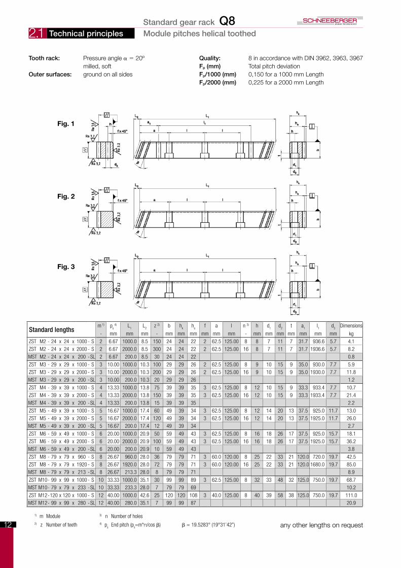
Tooth rack: Pressure angle α = 20º Quality: 8 in accordance with DIN 3962, 3963, 3967 milled, soft Fp (mm) Total pitch deviationOuter surfaces: ground on all sides Fp/1000 (mm) 0,150 for a 1000 mm Length Fp/2000 (mm) 0,225 for a 2000 mm Length
Standard lengthsm 1) p
s 4) L
1L
2z 2) b h
kh
of a l n 3) h d
1d
2t a
1l1
d3
Dimensions
- mm mm mm - mm mm mm mm mm mm - mm mm mm mm mm mm mm kg
ZST M2 - 24 x 24 x 1000 - S 2 6.67 1000.0 8.5 150 24 24 22 2 62.5 125.00 8 8 7 11 7 31.7 936.6 5.7 4.1ZST M2 - 24 x 24 x 2000 - S 2 6.67 2000.0 8.5 300 24 24 22 2 62.5 125.00 16 8 7 11 7 31.7 1936.6 5.7 8.2MST M2 - 24 x 24 x 200 -SL 2 6.67 200.0 8.5 30 24 24 22 0.8
ZST M3 - 29 x 29 x 1000 - S 3 10.00 1000.0 10.3 100 29 29 26 2 62.5 125.00 8 9 10 15 9 35.0 930.0 7.7 5.9ZST M3 - 29 x 29 x 2000 - S 3 10.00 2000.0 10.3 200 29 29 26 2 62.5 125.00 16 9 10 15 9 35.0 1930.0 7.7 11.8MST M3 - 29 x 29 x 200 -SL 3 10.00 200.0 10.3 20 29 29 26 1.2
ZST M4 - 39 x 39 x 1000 - S 4 13.33 1000.0 13.8 75 39 39 35 3 62.5 125.00 8 12 10 15 9 33.3 933.4 7.7 10.7ZST M4 - 39 x 39 x 2000 - S 4 13.33 2000.0 13.8 150 39 39 35 3 62.5 125.00 16 12 10 15 9 33.3 1933.4 7.7 21.4MST M4 - 39 x 39 x 200 -SL 4 13.33 200.0 13.8 15 39 39 35 2.2
ZST M5 - 49 x 39 x 1000 - S 5 16.67 1000.0 17.4 60 49 39 34 3 62.5 125.00 8 12 14 20 13 37.5 925.0 11.7 13.0ZST M5 - 49 x 39 x 2000 - S 5 16.67 2000.0 17.4 120 49 39 34 3 62.5 125.00 16 12 14 20 13 37.5 1925.0 11.7 26.0MST M5 - 49 x 39 x 200 -SL 5 16.67 200.0 17.4 12 49 39 34 2.7
ZST M6 - 59 x 49 x 1000 - S 6 20.00 1000.0 20.9 50 59 49 43 3 62.5 125.00 8 16 18 26 17 37.5 925.0 15.7 18.1ZST M6 - 59 x 49 x 2000 - S 6 20.00 2000.0 20.9 100 59 49 43 3 62.5 125.00 16 16 18 26 17 37.5 1925.0 15.7 36.2MST M6 - 59 x 49 x 200 -SL 6 20.00 200.0 20.9 10 59 49 43 3.8
ZST M8 - 79 x 79 x 960 - S 8 26.67 960.0 28.0 36 79 79 71 3 60.0 120.00 8 25 22 33 21 120.0 720.0 19.7 42.5ZST M8 - 79 x 79 x 1920 - S 8 26.67 1920.0 28.0 72 79 79 71 3 60.0 120.00 16 25 22 33 21 120.0 1680.0 19.7 85.0MST M8 - 79 x 79 x 213 -SL 8 26.67 213.3 28.0 8 79 79 71 8.9
ZST M10- 99 x 99 x 1000 - S 10 33.33 1000.0 35.1 30 99 99 89 3 62.5 125.00 8 32 33 48 32 125.0 750.0 19.7 68.7MST M10- 79 x 79 x 233 -SL 10 33.33 233.3 28.0 7 79 79 69 10.2
ZST M12-120 x 120 x 1000 - S 12 40.00 1000.0 42.6 25 120 120 108 3 40.0 125.00 8 40 39 58 38 125.0 750.0 19.7 111.0MST M12- 99 x 99 x 280 -SL 12 40.00 280.0 35.1 7 99 99 87 20.9
any other lengths on request
Fig. 1
Fig. 2
Fig. 3
Technical principles Module pitches helical toothed
1) m Module 3) n Number of holes2) z Number of teeth 4) p
sEnd pitch (p
s=m*π/cos β) β = 19.5283° (19°31’42”)
Standard gear rack Q8
13
2.1
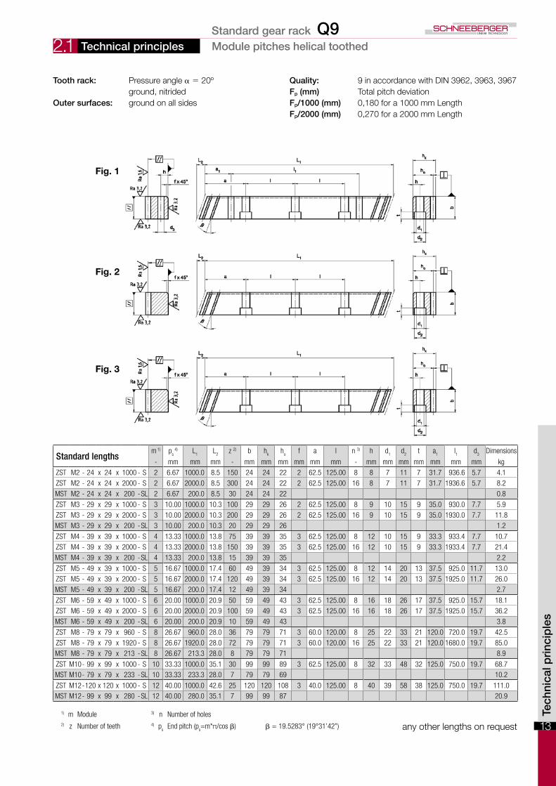
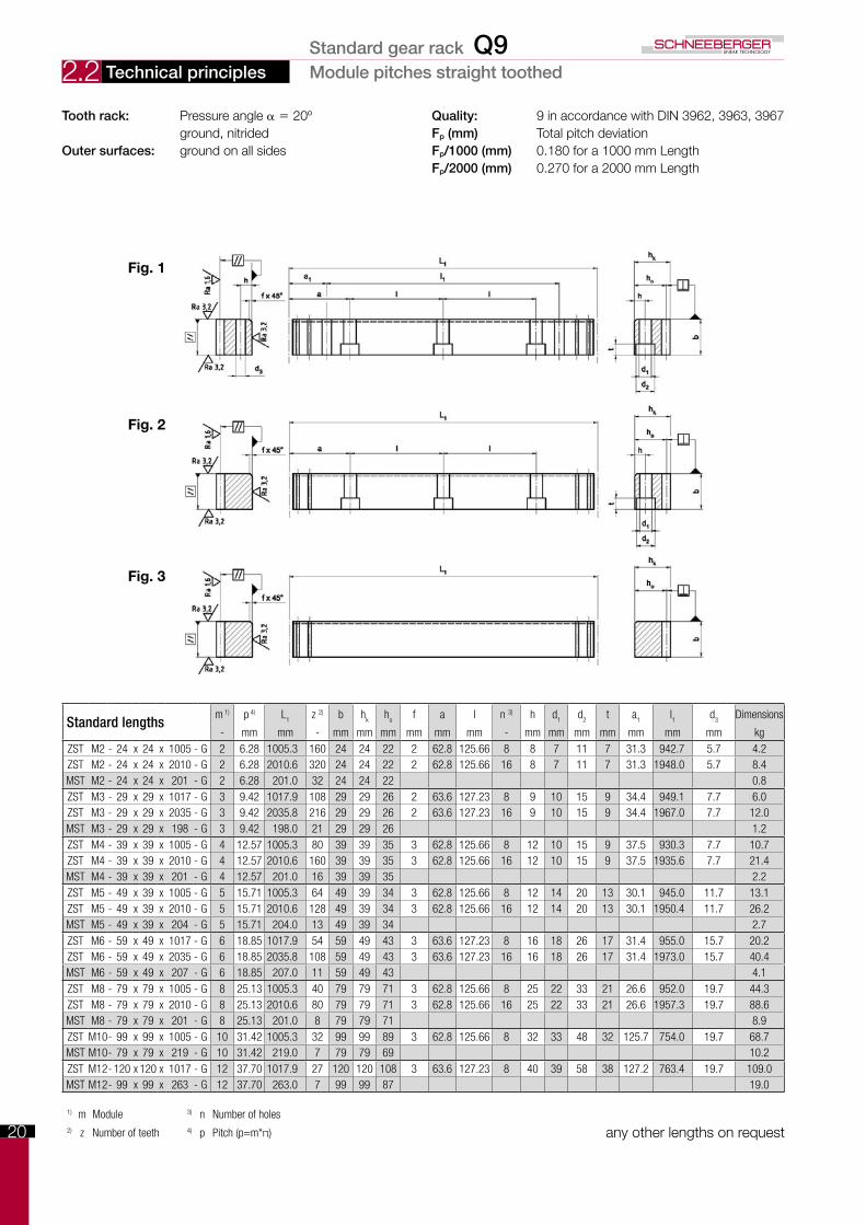
Tooth rack: Pressure angle α = 20º Quality: 9 in accordance with DIN 3962, 3963, 3967 ground, nitrided Fp (mm) Total pitch deviationOuter surfaces: ground on all sides Fp/1000 (mm) 0,180 for a 1000 mm Length Fp/2000 (mm) 0,270 for a 2000 mm Length
Standard lengthsm 1) p
s 4) L
1L
2z 2) b h
kh
of a l n 3) h d
1d
2t a
1l1
d3
Dimensions
- mm mm mm - mm mm mm mm mm mm - mm mm mm mm mm mm mm kg
ZST M2 - 24 x 24 x 1000 - S 2 6.67 1000.0 8.5 150 24 24 22 2 62.5 125.00 8 8 7 11 7 31.7 936.6 5.7 4.1ZST M2 - 24 x 24 x 2000 - S 2 6.67 2000.0 8.5 300 24 24 22 2 62.5 125.00 16 8 7 11 7 31.7 1936.6 5.7 8.2MST M2 - 24 x 24 x 200 -SL 2 6.67 200.0 8.5 30 24 24 22 0.8
ZST M3 - 29 x 29 x 1000 - S 3 10.00 1000.0 10.3 100 29 29 26 2 62.5 125.00 8 9 10 15 9 35.0 930.0 7.7 5.9ZST M3 - 29 x 29 x 2000 - S 3 10.00 2000.0 10.3 200 29 29 26 2 62.5 125.00 16 9 10 15 9 35.0 1930.0 7.7 11.8MST M3 - 29 x 29 x 200 -SL 3 10.00 200.0 10.3 20 29 29 26 1.2
ZST M4 - 39 x 39 x 1000 - S 4 13.33 1000.0 13.8 75 39 39 35 3 62.5 125.00 8 12 10 15 9 33.3 933.4 7.7 10.7ZST M4 - 39 x 39 x 2000 - S 4 13.33 2000.0 13.8 150 39 39 35 3 62.5 125.00 16 12 10 15 9 33.3 1933.4 7.7 21.4MST M4 - 39 x 39 x 200 -SL 4 13.33 200.0 13.8 15 39 39 35 2.2
ZST M5 - 49 x 39 x 1000 - S 5 16.67 1000.0 17.4 60 49 39 34 3 62.5 125.00 8 12 14 20 13 37.5 925.0 11.7 13.0ZST M5 - 49 x 39 x 2000 - S 5 16.67 2000.0 17.4 120 49 39 34 3 62.5 125.00 16 12 14 20 13 37.5 1925.0 11.7 26.0MST M5 - 49 x 39 x 200 -SL 5 16.67 200.0 17.4 12 49 39 34 2.7
ZST M6 - 59 x 49 x 1000 - S 6 20.00 1000.0 20.9 50 59 49 43 3 62.5 125.00 8 16 18 26 17 37.5 925.0 15.7 18.1ZST M6 - 59 x 49 x 2000 - S 6 20.00 2000.0 20.9 100 59 49 43 3 62.5 125.00 16 16 18 26 17 37.5 1925.0 15.7 36.2MST M6 - 59 x 49 x 200 -SL 6 20.00 200.0 20.9 10 59 49 43 3.8
ZST M8 - 79 x 79 x 960 - S 8 26.67 960.0 28.0 36 79 79 71 3 60.0 120.00 8 25 22 33 21 120.0 720.0 19.7 42.5ZST M8 - 79 x 79 x 1920 - S 8 26.67 1920.0 28.0 72 79 79 71 3 60.0 120.00 16 25 22 33 21 120.0 1680.0 19.7 85.0MST M8 - 79 x 79 x 213 -SL 8 26.67 213.3 28.0 8 79 79 71 8.9
ZST M10- 99 x 99 x 1000 - S 10 33.33 1000.0 35.1 30 99 99 89 3 62.5 125.00 8 32 33 48 32 125.0 750.0 19.7 68.7MST M10- 79 x 79 x 233 -SL 10 33.33 233.3 28.0 7 79 79 69 10.2
ZST M12-120 x 120 x 1000 - S 12 40.00 1000.0 42.6 25 120 120 108 3 40.0 125.00 8 40 39 58 38 125.0 750.0 19.7 111.0MST M12- 99 x 99 x 280 -SL 12 40.00 280.0 35.1 7 99 99 87 20.9
any other lengths on request
Fig. 1
Fig. 2
Fig. 3
Tech
nica
l pri
ncip
les
Technical principles Module pitches helical toothed
1) m Module 3) n Number of holes2) z Number of teeth 4) p
sEnd pitch (p
s=m*π/cos β) β = 19.5283° (19°31’42”)
Standard gear rack Q9

14
2.1
Tooth rack: Pressure angle α = 20º Quality: 11 in accordance with DIN 3962, 3963, 3967 milled, induction hardened Fp (mm) Total pitch deviationOuter surfaces: ground on all sides Fp/1000 (mm) 0,220 for a 1000 mm Length Fp/2000 (mm) 0,330 for a 2000 mm Length
Standard lengthsm 1) p
s 4) L
1L
2z 2) b h
kh
of a l n 3) h d
1d
2t a
1l1
d3
Dimensions
- mm mm mm - mm mm mm mm mm mm - mm mm mm mm mm mm mm kg
ZST M2 - 24 x 24 x 1000 - S 2 6.67 1000.0 8.5 150 24 24 22 2 62.5 125.00 8 8 7 11 7 31.7 936.6 5.7 4.1ZST M2 - 24 x 24 x 2000 - S 2 6.67 2000.0 8.5 300 24 24 22 2 62.5 125.00 16 8 7 11 7 31.7 1936.6 5.7 8.2MST M2 - 24 x 24 x 200 -SL 2 6.67 200.0 8.5 30 24 24 22 0.8
ZST M3 - 29 x 29 x 1000 - S 3 10.00 1000.0 10.3 100 29 29 26 2 62.5 125.00 8 9 10 15 9 35.0 930.0 7.7 5.9ZST M3 - 29 x 29 x 2000 - S 3 10.00 2000.0 10.3 200 29 29 26 2 62.5 125.00 16 9 10 15 9 35.0 1930.0 7.7 11.8MST M3 - 29 x 29 x 200 -SL 3 10.00 200.0 10.3 20 29 29 26 1.2
ZST M4 - 39 x 39 x 1000 - S 4 13.33 1000.0 13.8 75 39 39 35 3 62.5 125.00 8 12 10 15 9 33.3 933.4 7.7 10.7ZST M4 - 39 x 39 x 2000 - S 4 13.33 2000.0 13.8 150 39 39 35 3 62.5 125.00 16 12 10 15 9 33.3 1933.4 7.7 21.4MST M4 - 39 x 39 x 200 -SL 4 13.33 200.0 13.8 15 39 39 35 2.2
ZST M5 - 49 x 39 x 1000 - S 5 16.67 1000.0 17.4 60 49 39 34 3 62.5 125.00 8 12 14 20 13 37.5 925.0 11.7 13.0ZST M5 - 49 x 39 x 2000 - S 5 16.67 2000.0 17.4 120 49 39 34 3 62.5 125.00 16 12 14 20 13 37.5 1925.0 11.7 26.0MST M5 - 49 x 39 x 200 -SL 5 16.67 200.0 17.4 12 49 39 34 2.7
ZST M6 - 59 x 49 x 1000 - S 6 20.00 1000.0 20.9 50 59 49 43 3 62.5 125.00 8 16 18 26 17 37.5 925.0 15.7 18.1ZST M6 - 59 x 49 x 2000 - S 6 20.00 2000.0 20.9 100 59 49 43 3 62.5 125.00 16 16 18 26 17 37.5 1925.0 15.7 36.2MST M6 - 59 x 49 x 200 -SL 6 20.00 200.0 20.9 10 59 49 43 3.8
ZST M8 - 79 x 79 x 960 - S 8 26.67 960.0 28.0 36 79 79 71 3 60.0 120.00 8 25 22 33 21 120.0 720.0 19.7 42.5ZST M8 - 79 x 79 x 1920 - S 8 26.67 1920.0 28.0 72 79 79 71 3 60.0 120.00 16 25 22 33 21 120.0 1680.0 19.7 85.0MST M8 - 79 x 79 x 213 -SL 8 26.67 213.3 28.0 8 79 79 71 8.9
ZST M10- 99 x 99 x 1000 - S 10 33.33 1000.0 35.1 30 99 99 89 3 62.5 125.00 8 32 33 48 32 125.0 750.0 19.7 68.7MST M10- 79 x 79 x 233 -SL 10 33.33 233.3 28.0 7 79 79 69 10.2
ZST M12-120 x 120 x 1000 - S 12 40.00 1000.0 42.6 25 120 120 108 3 40.0 125.00 8 40 39 58 38 125.0 750.0 19.7 111.0MST M12- 99 x 99 x 280 -SL 12 40.00 280.0 35.1 7 99 99 87 20.9
any other lengths on request
Fig. 1
Fig. 2
Fig. 3
Technical principles Module pitches helical toothed
1) m Module 3) n Number of holes2) z Number of teeth 4) p
sEnd pitch (p
s=m*π/cos β) β = 19.5283° (19°31’42”)
Standard gear rack Q11

15
2.2
Tech
nica
l pri
ncip
les
1) m Module 3) n Number of holes2) z Number of teeth 4) p Pitch (p=m*π) any other lengths on request
Tooth rack: Pressure angle α = 20º Quality: 4 in accordance with DIN 3962, 3963, 3967 ground, soft or hardened fp (mm) Single pitch deviationOuter surfaces: groundonallsides Module≤3:0.003 Module > 3: 0.004 Fp (mm) Total pitch deviation Fp/1000 (mm) 0,015 for a 1000 mm Length
Fig. 1
Fig. 2
Fig. 3
Technical principles Module pitches straight toothed
Standard lengthsm 1) p 4) L
1z 2) b h
kh
of a l n 3) h d
1d
2t a
1l1
d3
Dimensions
- mm mm - mm mm mm mm mm mm - mm mm mm mm mm mm mm kgZST M2 - 24 x 24 x 1005 - G 2 6.28 1005.3 160 24 24 22 2 62.8 125.66 8 8 7 11 7 31.3 942.7 5.7 4.2ZST M2 - 24 x 24 x 2010 - G 2 6.28 2010.6 320 24 24 22 2 62.8 125.66 16 8 7 11 7 31.3 1948.0 5.7 8.4MST M2 - 24 x 24 x 201 - G 2 6.28 201.0 32 24 24 22 0.8ZST M3 - 29 x 29 x 1017 - G 3 9.42 1017.9 108 29 29 26 2 63.6 127.23 8 9 10 15 9 34.4 949.1 7.7 6.0ZST M3 - 29 x 29 x 2035 - G 3 9.42 2035.8 216 29 29 26 2 63.6 127.23 16 9 10 15 9 34.4 1967.0 7.7 12.0MST M3 - 29 x 29 x 198 - G 3 9.42 198.0 21 29 29 26 1.2ZST M4 - 39 x 39 x 1005 - G 4 12.57 1005.3 80 39 39 35 3 62.8 125.66 8 12 10 15 9 37.5 930.3 7.7 10.7ZST M4 - 39 x 39 x 2010 - G 4 12.57 2010.6 160 39 39 35 3 62.8 125.66 16 12 10 15 9 37.5 1935.6 7.7 21.4MST M4 - 39 x 39 x 201 - G 4 12.57 201.0 16 39 39 35 2.2ZST M5 - 49 x 39 x 1005 - G 5 15.71 1005.3 64 49 39 34 3 62.8 125.66 8 12 14 20 13 30.1 945.0 11.7 13.1ZST M5 - 49 x 39 x 2010 - G 5 15.71 2010.6 128 49 39 34 3 62.8 125.66 16 12 14 20 13 30.1 1950.4 11.7 26.2MST M5 - 49 x 39 x 204 - G 5 15.71 204.0 13 49 39 34 2.7ZST M6 - 59 x 49 x 1017 - G 6 18.85 1017.9 54 59 49 43 3 63.6 127.23 8 16 18 26 17 31.4 955.0 15.7 20.2ZST M6 - 59 x 49 x 2035 - G 6 18.85 2035.8 108 59 49 43 3 63.6 127.23 16 16 18 26 17 31.4 1973.0 15.7 40.4MST M6 - 59 x 49 x 207 - G 6 18.85 207.0 11 59 49 43 4.1ZST M8 - 79 x 79 x 1005 - G 8 25.13 1005.3 40 79 79 71 3 62.8 125.66 8 25 22 33 21 26.6 952.0 19.7 44.3ZST M8 - 79 x 79 x 2010 - G 8 25.13 2010.6 80 79 79 71 3 62.8 125.66 16 25 22 33 21 26.6 1957.3 19.7 88.6MST M8 - 79 x 79 x 201 - G 8 25.13 201.0 8 79 79 71 8.9ZST M10- 99 x 99 x 1005 - G 10 31.42 1005.3 32 99 99 89 3 62.8 125.66 8 32 33 48 32 125.7 754.0 19.7 68.7MST M10- 79 x 79 x 219 - G 10 31.42 219.0 7 79 79 69 10.2ZST M12- 120 x 120 x 1017 - G 12 37.70 1017.9 27 120 120 108 3 63.6 127.23 8 40 39 58 38 127.2 763.4 19.7 109.0MST M12- 99 x 99 x 263 - G 12 37.70 263.0 7 99 99 87 19.0
Standard gear rack Q4

16
2.2
Standard lengthsm 1) p 4) L
1z 2) b h
kh
of a l n 3) h d
1d
2t a
1l1
d3
Dimensions
- mm mm - mm mm mm mm mm mm - mm mm mm mm mm mm mm kgZST M2 - 24 x 24 x 1005 - G 2 6.28 1005.3 160 24 24 22 2 62.8 125.66 8 8 7 11 7 31.3 942.7 5.7 4.2ZST M2 - 24 x 24 x 2010 - G 2 6.28 2010.6 320 24 24 22 2 62.8 125.66 16 8 7 11 7 31.3 1948.0 5.7 8.4MST M2 - 24 x 24 x 201 - G 2 6.28 201.0 32 24 24 22 0.8
ZST M3 - 29 x 29 x 1017 - G 3 9.42 1017.9 108 29 29 26 2 63.6 127.23 8 9 10 15 9 34.4 949.1 7.7 6.0ZST M3 - 29 x 29 x 2035 - G 3 9.42 2035.8 216 29 29 26 2 63.6 127.23 16 9 10 15 9 34.4 1967.0 7.7 12.0MST M3 - 29 x 29 x 198 - G 3 9.42 198.0 21 29 29 26 1.2
ZST M4 - 39 x 39 x 1005 - G 4 12.57 1005.3 80 39 39 35 3 62.8 125.66 8 12 10 15 9 37.5 930.3 7.7 10.7ZST M4 - 39 x 39 x 2010 - G 4 12.57 2010.6 160 39 39 35 3 62.8 125.66 16 12 10 15 9 37.5 1935.6 7.7 21.4MST M4 - 39 x 39 x 201 - G 4 12.57 201.0 16 39 39 35 2.2
ZST M5 - 49 x 39 x 1005 - G 5 15.71 1005.3 64 49 39 34 3 62.8 125.66 8 12 14 20 13 30.1 945.0 11.7 13.1ZST M5 - 49 x 39 x 2010 - G 5 15.71 2010.6 128 49 39 34 3 62.8 125.66 16 12 14 20 13 30.1 1950.4 11.7 26.2MST M5 - 49 x 39 x 204 - G 5 15.71 204.0 13 49 39 34 2.7
ZST M6 - 59 x 49 x 1017 - G 6 18.85 1017.9 54 59 49 43 3 63.6 127.23 8 16 18 26 17 31.4 955.0 15.7 20.2ZST M6 - 59 x 49 x 2035 - G 6 18.85 2035.8 108 59 49 43 3 63.6 127.23 16 16 18 26 17 31.4 1973.0 15.7 40.4MST M6 - 59 x 49 x 207 - G 6 18.85 207.0 11 59 49 43 4.1
ZST M8 - 79 x 79 x 1005 - G 8 25.13 1005.3 40 79 79 71 3 62.8 125.66 8 25 22 33 21 26.6 952.0 19.7 44.3ZST M8 - 79 x 79 x 2010 - G 8 25.13 2010.6 80 79 79 71 3 62.8 125.66 16 25 22 33 21 26.6 1957.3 19.7 88.6MST M8 - 79 x 79 x 201 - G 8 25.13 201.0 8 79 79 71 8.9
ZST M10- 99 x 99 x 1005 - G 10 31.42 1005.3 32 99 99 89 3 62.8 125.66 8 32 33 48 32 125.7 754.0 19.7 68.7MST M10- 79 x 79 x 219 - G 10 31.42 219.0 7 79 79 69 10.2
ZST M12- 120 x 120 x 1017 - G 12 37.70 1017.9 27 120 120 108 3 63.6 127.23 8 40 39 58 38 127.2 763.4 19.7 109.0MST M12- 99 x 99 x 263 - G 12 37.70 263.0 7 99 99 87 19.0
1) m Module 3) n Number of holes2) z Number of teeth 4) p Pitch (p=m*π) any other lengths on request
Tooth rack: Pressure angle α = 20º Quality: 5 in accordance with DIN 3962, 3963, 3967 ground, soft or hardened fp (mm) Single pitch deviationOuter surfaces: groundonallsides Module≤3:0,004 Module > 3: 0,005 Fp (mm) Total pitch deviation Fp/1000 (mm) 0.024 for a 1000 mm length Fp/2000 (mm) 0.032 for a 2000 mm length
Fig. 1
Fig. 2
Fig. 3
Technical principles Module pitches straight toothedStandard gear rack Q5
17
2.2
1) m Module 3) n Number of holes2) z Number of teeth 4) p Pitch (p=m*π) any other lengths on request
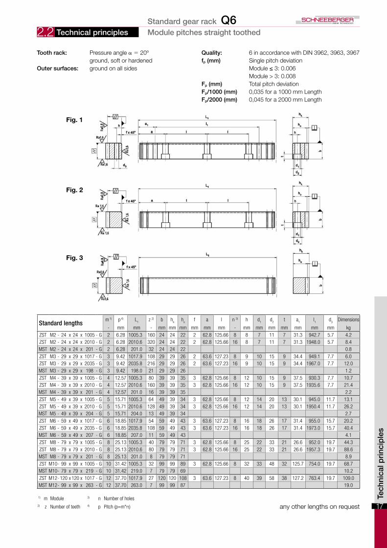
Tooth rack: Pressure angle α = 20º Quality: 6 in accordance with DIN 3962, 3963, 3967 ground, soft or hardened fp (mm) Single pitch deviationOuter surfaces: groundonallsides Module≤3:0.006 Module > 3: 0.008 Fp (mm) Total pitch deviation Fp/1000 (mm) 0,035 for a 1000 mm Length Fp/2000 (mm) 0,045 for a 2000 mm Length
Fig. 1
Fig. 2
Fig. 3
Technical principles Module pitches straight toothed
Standard lengthsm 1) p 4) L
1z 2) b h
kh
of a l n 3) h d
1d
2t a
1l1
d3
Dimensions
- mm mm - mm mm mm mm mm mm - mm mm mm mm mm mm mm kgZST M2 - 24 x 24 x 1005 - G 2 6.28 1005.3 160 24 24 22 2 62.8 125.66 8 8 7 11 7 31.3 942.7 5.7 4.2ZST M2 - 24 x 24 x 2010 - G 2 6.28 2010.6 320 24 24 22 2 62.8 125.66 16 8 7 11 7 31.3 1948.0 5.7 8.4MST M2 - 24 x 24 x 201 - G 2 6.28 201.0 32 24 24 22 0.8ZST M3 - 29 x 29 x 1017 - G 3 9.42 1017.9 108 29 29 26 2 63.6 127.23 8 9 10 15 9 34.4 949.1 7.7 6.0ZST M3 - 29 x 29 x 2035 - G 3 9.42 2035.8 216 29 29 26 2 63.6 127.23 16 9 10 15 9 34.4 1967.0 7.7 12.0MST M3 - 29 x 29 x 198 - G 3 9.42 198.0 21 29 29 26 1.2ZST M4 - 39 x 39 x 1005 - G 4 12.57 1005.3 80 39 39 35 3 62.8 125.66 8 12 10 15 9 37.5 930.3 7.7 10.7ZST M4 - 39 x 39 x 2010 - G 4 12.57 2010.6 160 39 39 35 3 62.8 125.66 16 12 10 15 9 37.5 1935.6 7.7 21.4MST M4 - 39 x 39 x 201 - G 4 12.57 201.0 16 39 39 35 2.2ZST M5 - 49 x 39 x 1005 - G 5 15.71 1005.3 64 49 39 34 3 62.8 125.66 8 12 14 20 13 30.1 945.0 11.7 13.1ZST M5 - 49 x 39 x 2010 - G 5 15.71 2010.6 128 49 39 34 3 62.8 125.66 16 12 14 20 13 30.1 1950.4 11.7 26.2MST M5 - 49 x 39 x 204 - G 5 15.71 204.0 13 49 39 34 2.7ZST M6 - 59 x 49 x 1017 - G 6 18.85 1017.9 54 59 49 43 3 63.6 127.23 8 16 18 26 17 31.4 955.0 15.7 20.2ZST M6 - 59 x 49 x 2035 - G 6 18.85 2035.8 108 59 49 43 3 63.6 127.23 16 16 18 26 17 31.4 1973.0 15.7 40.4MST M6 - 59 x 49 x 207 - G 6 18.85 207.0 11 59 49 43 4.1ZST M8 - 79 x 79 x 1005 - G 8 25.13 1005.3 40 79 79 71 3 62.8 125.66 8 25 22 33 21 26.6 952.0 19.7 44.3ZST M8 - 79 x 79 x 2010 - G 8 25.13 2010.6 80 79 79 71 3 62.8 125.66 16 25 22 33 21 26.6 1957.3 19.7 88.6MST M8 - 79 x 79 x 201 - G 8 25.13 201.0 8 79 79 71 8.9ZST M10- 99 x 99 x 1005 - G 10 31.42 1005.3 32 99 99 89 3 62.8 125.66 8 32 33 48 32 125.7 754.0 19.7 68.7MST M10- 79 x 79 x 219 - G 10 31.42 219.0 7 79 79 69 10.2ZST M12- 120 x 120 x 1017 - G 12 37.70 1017.9 27 120 120 108 3 63.6 127.23 8 40 39 58 38 127.2 763.4 19.7 109.0MST M12- 99 x 99 x 263 - G 12 37.70 263.0 7 99 99 87 19.0
Standard gear rack Q6
Tech
nica
l pri
ncip
les
18
2.2
Standard lengthsm 1) p 4) L
1z 2) b h
kh
of a l n 3) h d
1d
2t a
1l1
d3
Dimensions
- mm mm - mm mm mm mm mm mm - mm mm mm mm mm mm mm kgZST M2 - 24 x 24 x 1005 - G 2 6.28 1005.3 160 24 24 22 2 62.8 125.66 8 8 7 11 7 31.3 942.7 5.7 4.2ZST M2 - 24 x 24 x 2010 - G 2 6.28 2010.6 320 24 24 22 2 62.8 125.66 16 8 7 11 7 31.3 1948.0 5.7 8.4MST M2 - 24 x 24 x 201 - G 2 6.28 201.0 32 24 24 22 0.8
ZST M3 - 29 x 29 x 1017 - G 3 9.42 1017.9 108 29 29 26 2 63.6 127.23 8 9 10 15 9 34.4 949.1 7.7 6.0ZST M3 - 29 x 29 x 2035 - G 3 9.42 2035.8 216 29 29 26 2 63.6 127.23 16 9 10 15 9 34.4 1967.0 7.7 12.0MST M3 - 29 x 29 x 198 - G 3 9.42 198.0 21 29 29 26 1.2
ZST M4 - 39 x 39 x 1005 - G 4 12.57 1005.3 80 39 39 35 3 62.8 125.66 8 12 10 15 9 37.5 930.3 7.7 10.7ZST M4 - 39 x 39 x 2010 - G 4 12.57 2010.6 160 39 39 35 3 62.8 125.66 16 12 10 15 9 37.5 1935.6 7.7 21.4MST M4 - 39 x 39 x 201 - G 4 12.57 201.0 16 39 39 35 2.2
ZST M5 - 49 x 39 x 1005 - G 5 15.71 1005.3 64 49 39 34 3 62.8 125.66 8 12 14 20 13 30.1 945.0 11.7 13.1ZST M5 - 49 x 39 x 2010 - G 5 15.71 2010.6 128 49 39 34 3 62.8 125.66 16 12 14 20 13 30.1 1950.4 11.7 26.2MST M5 - 49 x 39 x 204 - G 5 15.71 204.0 13 49 39 34 2.7
ZST M6 - 59 x 49 x 1017 - G 6 18.85 1017.9 54 59 49 43 3 63.6 127.23 8 16 18 26 17 31.4 955.0 15.7 20.2ZST M6 - 59 x 49 x 2035 - G 6 18.85 2035.8 108 59 49 43 3 63.6 127.23 16 16 18 26 17 31.4 1973.0 15.7 40.4MST M6 - 59 x 49 x 207 - G 6 18.85 207.0 11 59 49 43 4.1
ZST M8 - 79 x 79 x 1005 - G 8 25.13 1005.3 40 79 79 71 3 62.8 125.66 8 25 22 33 21 26.6 952.0 19.7 44.3ZST M8 - 79 x 79 x 2010 - G 8 25.13 2010.6 80 79 79 71 3 62.8 125.66 16 25 22 33 21 26.6 1957.3 19.7 88.6MST M8 - 79 x 79 x 201 - G 8 25.13 201.0 8 79 79 71 8.9
ZST M10- 99 x 99 x 1005 - G 10 31.42 1005.3 32 99 99 89 3 62.8 125.66 8 32 33 48 32 125.7 754.0 19.7 68.7MST M10- 79 x 79 x 219 - G 10 31.42 219.0 7 79 79 69 10.2
ZST M12- 120 x 120 x 1017 - G 12 37.70 1017.9 27 120 120 108 3 63.6 127.23 8 40 39 58 38 127.2 763.4 19.7 109.0MST M12- 99 x 99 x 263 - G 12 37.70 263.0 7 99 99 87 19.0
1) m Module 3) n Number of holes2) z Number of teeth 4) p Pitch (p=m*π) any other lengths on request
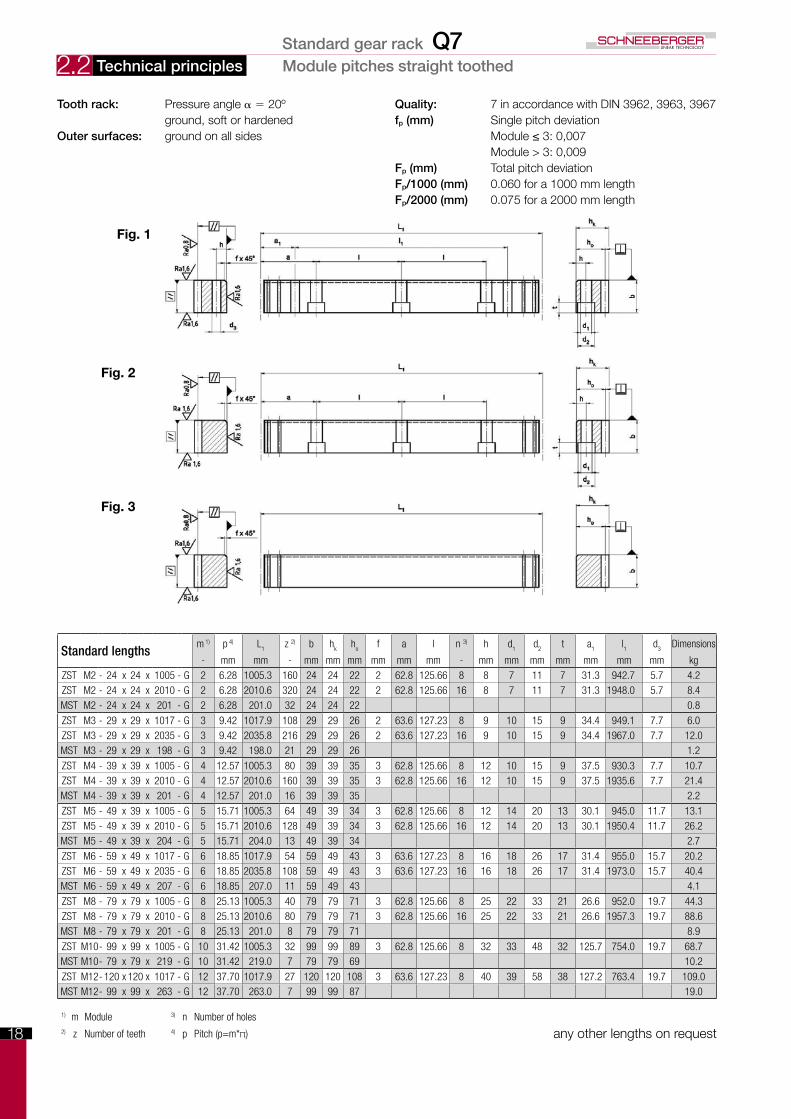
Tooth rack: Pressure angle α = 20º Quality: 7 in accordance with DIN 3962, 3963, 3967 ground, soft or hardened fp (mm) Single pitch deviationOuter surfaces: groundonallsides Module≤3:0,007 Module > 3: 0,009 Fp (mm) Total pitch deviation Fp/1000 (mm) 0.060 for a 1000 mm length Fp/2000 (mm) 0.075 for a 2000 mm length
Fig. 1
Fig. 2
Fig. 3
Technical principles Module pitches straight toothedStandard gear rack Q7
19
2.2
Tech
nica
l pri
ncip
les
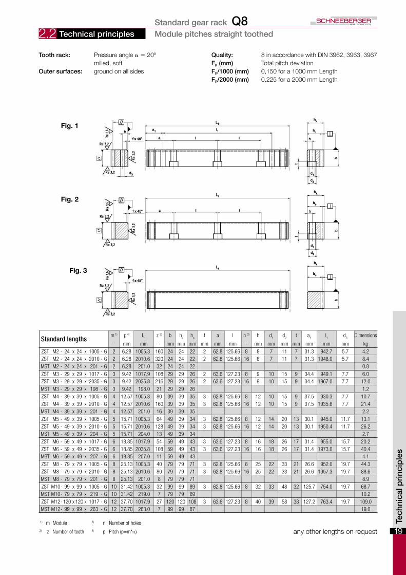
Tooth rack: Pressure angle α = 20º Quality: 8 in accordance with DIN 3962, 3963, 3967 milled, soft Fp (mm) Total pitch deviationOuter surfaces: ground on all sides Fp/1000 (mm) 0,150 for a 1000 mm Length Fp/2000 (mm) 0,225 for a 2000 mm Length
1) m Module 3) n Number of holes2) z Number of teeth 4) p Pitch (p=m*π) any other lengths on request
Fig. 1
Fig. 2
Fig. 3
Technical principles Module pitches straight toothed
Standard lengthsm 1) p 4) L
1z 2) b h
kh
of a l n 3) h d
1d
2t a
1l1
d3
Dimensions
- mm mm - mm mm mm mm mm mm - mm mm mm mm mm mm mm kgZST M2 - 24 x 24 x 1005 - G 2 6.28 1005.3 160 24 24 22 2 62.8 125.66 8 8 7 11 7 31.3 942.7 5.7 4.2ZST M2 - 24 x 24 x 2010 - G 2 6.28 2010.6 320 24 24 22 2 62.8 125.66 16 8 7 11 7 31.3 1948.0 5.7 8.4MST M2 - 24 x 24 x 201 - G 2 6.28 201.0 32 24 24 22 0.8ZST M3 - 29 x 29 x 1017 - G 3 9.42 1017.9 108 29 29 26 2 63.6 127.23 8 9 10 15 9 34.4 949.1 7.7 6.0ZST M3 - 29 x 29 x 2035 - G 3 9.42 2035.8 216 29 29 26 2 63.6 127.23 16 9 10 15 9 34.4 1967.0 7.7 12.0MST M3 - 29 x 29 x 198 - G 3 9.42 198.0 21 29 29 26 1.2ZST M4 - 39 x 39 x 1005 - G 4 12.57 1005.3 80 39 39 35 3 62.8 125.66 8 12 10 15 9 37.5 930.3 7.7 10.7ZST M4 - 39 x 39 x 2010 - G 4 12.57 2010.6 160 39 39 35 3 62.8 125.66 16 12 10 15 9 37.5 1935.6 7.7 21.4MST M4 - 39 x 39 x 201 - G 4 12.57 201.0 16 39 39 35 2.2ZST M5 - 49 x 39 x 1005 - G 5 15.71 1005.3 64 49 39 34 3 62.8 125.66 8 12 14 20 13 30.1 945.0 11.7 13.1ZST M5 - 49 x 39 x 2010 - G 5 15.71 2010.6 128 49 39 34 3 62.8 125.66 16 12 14 20 13 30.1 1950.4 11.7 26.2MST M5 - 49 x 39 x 204 - G 5 15.71 204.0 13 49 39 34 2.7ZST M6 - 59 x 49 x 1017 - G 6 18.85 1017.9 54 59 49 43 3 63.6 127.23 8 16 18 26 17 31.4 955.0 15.7 20.2ZST M6 - 59 x 49 x 2035 - G 6 18.85 2035.8 108 59 49 43 3 63.6 127.23 16 16 18 26 17 31.4 1973.0 15.7 40.4MST M6 - 59 x 49 x 207 - G 6 18.85 207.0 11 59 49 43 4.1ZST M8 - 79 x 79 x 1005 - G 8 25.13 1005.3 40 79 79 71 3 62.8 125.66 8 25 22 33 21 26.6 952.0 19.7 44.3ZST M8 - 79 x 79 x 2010 - G 8 25.13 2010.6 80 79 79 71 3 62.8 125.66 16 25 22 33 21 26.6 1957.3 19.7 88.6MST M8 - 79 x 79 x 201 - G 8 25.13 201.0 8 79 79 71 8.9ZST M10- 99 x 99 x 1005 - G 10 31.42 1005.3 32 99 99 89 3 62.8 125.66 8 32 33 48 32 125.7 754.0 19.7 68.7MST M10- 79 x 79 x 219 - G 10 31.42 219.0 7 79 79 69 10.2ZST M12- 120 x 120 x 1017 - G 12 37.70 1017.9 27 120 120 108 3 63.6 127.23 8 40 39 58 38 127.2 763.4 19.7 109.0MST M12- 99 x 99 x 263 - G 12 37.70 263.0 7 99 99 87 19.0
Standard gear rack Q8
20
2.2 Technical principles Module pitches straight toothed
1) m Module 3) n Number of holes2) z Number of teeth 4) p Pitch (p=m*π) any other lengths on request
Fig. 1
Fig. 2
Fig. 3
Tooth rack: Pressure angle α = 20º Quality: 9 in accordance with DIN 3962, 3963, 3967 ground, nitrided Fp (mm) Total pitch deviationOuter surfaces: ground on all sides Fp/1000 (mm) 0.180 for a 1000 mm Length Fp/2000 (mm) 0.270 for a 2000 mm Length
Standard lengthsm 1) p 4) L
1z 2) b h
kh
of a l n 3) h d
1d
2t a
1l1
d3
Dimensions
- mm mm - mm mm mm mm mm mm - mm mm mm mm mm mm mm kgZST M2 - 24 x 24 x 1005 - G 2 6.28 1005.3 160 24 24 22 2 62.8 125.66 8 8 7 11 7 31.3 942.7 5.7 4.2ZST M2 - 24 x 24 x 2010 - G 2 6.28 2010.6 320 24 24 22 2 62.8 125.66 16 8 7 11 7 31.3 1948.0 5.7 8.4MST M2 - 24 x 24 x 201 - G 2 6.28 201.0 32 24 24 22 0.8ZST M3 - 29 x 29 x 1017 - G 3 9.42 1017.9 108 29 29 26 2 63.6 127.23 8 9 10 15 9 34.4 949.1 7.7 6.0ZST M3 - 29 x 29 x 2035 - G 3 9.42 2035.8 216 29 29 26 2 63.6 127.23 16 9 10 15 9 34.4 1967.0 7.7 12.0MST M3 - 29 x 29 x 198 - G 3 9.42 198.0 21 29 29 26 1.2ZST M4 - 39 x 39 x 1005 - G 4 12.57 1005.3 80 39 39 35 3 62.8 125.66 8 12 10 15 9 37.5 930.3 7.7 10.7ZST M4 - 39 x 39 x 2010 - G 4 12.57 2010.6 160 39 39 35 3 62.8 125.66 16 12 10 15 9 37.5 1935.6 7.7 21.4MST M4 - 39 x 39 x 201 - G 4 12.57 201.0 16 39 39 35 2.2ZST M5 - 49 x 39 x 1005 - G 5 15.71 1005.3 64 49 39 34 3 62.8 125.66 8 12 14 20 13 30.1 945.0 11.7 13.1ZST M5 - 49 x 39 x 2010 - G 5 15.71 2010.6 128 49 39 34 3 62.8 125.66 16 12 14 20 13 30.1 1950.4 11.7 26.2MST M5 - 49 x 39 x 204 - G 5 15.71 204.0 13 49 39 34 2.7ZST M6 - 59 x 49 x 1017 - G 6 18.85 1017.9 54 59 49 43 3 63.6 127.23 8 16 18 26 17 31.4 955.0 15.7 20.2ZST M6 - 59 x 49 x 2035 - G 6 18.85 2035.8 108 59 49 43 3 63.6 127.23 16 16 18 26 17 31.4 1973.0 15.7 40.4MST M6 - 59 x 49 x 207 - G 6 18.85 207.0 11 59 49 43 4.1ZST M8 - 79 x 79 x 1005 - G 8 25.13 1005.3 40 79 79 71 3 62.8 125.66 8 25 22 33 21 26.6 952.0 19.7 44.3ZST M8 - 79 x 79 x 2010 - G 8 25.13 2010.6 80 79 79 71 3 62.8 125.66 16 25 22 33 21 26.6 1957.3 19.7 88.6MST M8 - 79 x 79 x 201 - G 8 25.13 201.0 8 79 79 71 8.9ZST M10- 99 x 99 x 1005 - G 10 31.42 1005.3 32 99 99 89 3 62.8 125.66 8 32 33 48 32 125.7 754.0 19.7 68.7MST M10- 79 x 79 x 219 - G 10 31.42 219.0 7 79 79 69 10.2ZST M12- 120 x 120 x 1017 - G 12 37.70 1017.9 27 120 120 108 3 63.6 127.23 8 40 39 58 38 127.2 763.4 19.7 109.0MST M12- 99 x 99 x 263 - G 12 37.70 263.0 7 99 99 87 19.0
Standard gear rack Q9
21
2.2 Technical principles Module pitches straight toothed
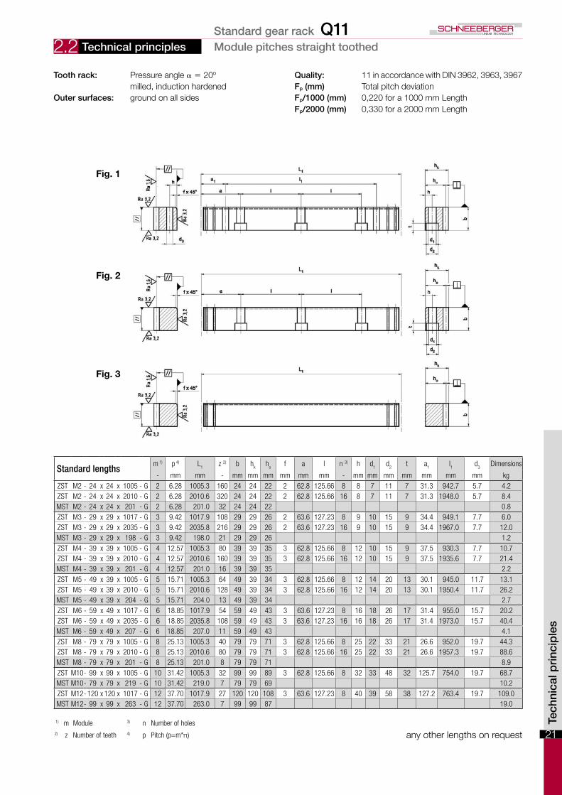
Tooth rack: Pressure angle α = 20º Quality: 11 in accordance with DIN 3962, 3963, 3967 milled, induction hardened Fp (mm) Total pitch deviationOuter surfaces: ground on all sides Fp/1000 (mm) 0,220 for a 1000 mm Length Fp/2000 (mm) 0,330 for a 2000 mm Length
1) m Module 3) n Number of holes2) z Number of teeth 4) p Pitch (p=m*π) any other lengths on request
Fig. 1
Fig. 2
Fig. 3
Tech
nica
l pri
ncip
les
Standard lengthsm 1) p 4) L
1z 2) b h
kh
of a l n 3) h d
1d
2t a
1l1
d3
Dimensions
- mm mm - mm mm mm mm mm mm - mm mm mm mm mm mm mm kgZST M2 - 24 x 24 x 1005 - G 2 6.28 1005.3 160 24 24 22 2 62.8 125.66 8 8 7 11 7 31.3 942.7 5.7 4.2ZST M2 - 24 x 24 x 2010 - G 2 6.28 2010.6 320 24 24 22 2 62.8 125.66 16 8 7 11 7 31.3 1948.0 5.7 8.4MST M2 - 24 x 24 x 201 - G 2 6.28 201.0 32 24 24 22 0.8ZST M3 - 29 x 29 x 1017 - G 3 9.42 1017.9 108 29 29 26 2 63.6 127.23 8 9 10 15 9 34.4 949.1 7.7 6.0ZST M3 - 29 x 29 x 2035 - G 3 9.42 2035.8 216 29 29 26 2 63.6 127.23 16 9 10 15 9 34.4 1967.0 7.7 12.0MST M3 - 29 x 29 x 198 - G 3 9.42 198.0 21 29 29 26 1.2ZST M4 - 39 x 39 x 1005 - G 4 12.57 1005.3 80 39 39 35 3 62.8 125.66 8 12 10 15 9 37.5 930.3 7.7 10.7ZST M4 - 39 x 39 x 2010 - G 4 12.57 2010.6 160 39 39 35 3 62.8 125.66 16 12 10 15 9 37.5 1935.6 7.7 21.4MST M4 - 39 x 39 x 201 - G 4 12.57 201.0 16 39 39 35 2.2ZST M5 - 49 x 39 x 1005 - G 5 15.71 1005.3 64 49 39 34 3 62.8 125.66 8 12 14 20 13 30.1 945.0 11.7 13.1ZST M5 - 49 x 39 x 2010 - G 5 15.71 2010.6 128 49 39 34 3 62.8 125.66 16 12 14 20 13 30.1 1950.4 11.7 26.2MST M5 - 49 x 39 x 204 - G 5 15.71 204.0 13 49 39 34 2.7ZST M6 - 59 x 49 x 1017 - G 6 18.85 1017.9 54 59 49 43 3 63.6 127.23 8 16 18 26 17 31.4 955.0 15.7 20.2ZST M6 - 59 x 49 x 2035 - G 6 18.85 2035.8 108 59 49 43 3 63.6 127.23 16 16 18 26 17 31.4 1973.0 15.7 40.4MST M6 - 59 x 49 x 207 - G 6 18.85 207.0 11 59 49 43 4.1ZST M8 - 79 x 79 x 1005 - G 8 25.13 1005.3 40 79 79 71 3 62.8 125.66 8 25 22 33 21 26.6 952.0 19.7 44.3ZST M8 - 79 x 79 x 2010 - G 8 25.13 2010.6 80 79 79 71 3 62.8 125.66 16 25 22 33 21 26.6 1957.3 19.7 88.6MST M8 - 79 x 79 x 201 - G 8 25.13 201.0 8 79 79 71 8.9ZST M10- 99 x 99 x 1005 - G 10 31.42 1005.3 32 99 99 89 3 62.8 125.66 8 32 33 48 32 125.7 754.0 19.7 68.7MST M10- 79 x 79 x 219 - G 10 31.42 219.0 7 79 79 69 10.2ZST M12- 120 x 120 x 1017 - G 12 37.70 1017.9 27 120 120 108 3 63.6 127.23 8 40 39 58 38 127.2 763.4 19.7 109.0MST M12- 99 x 99 x 263 - G 12 37.70 263.0 7 99 99 87 19.0
Standard gear rack Q11
22
2.3 Technical principles Metric pitch, straight toothed
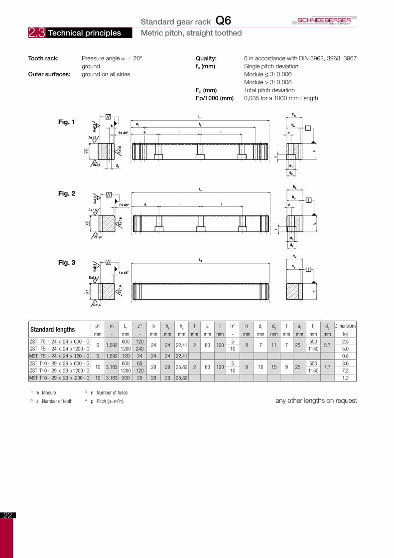
Tooth rack: Pressure angle α = 20º Quality: 6 in accordance with DIN 3962, 3963, 3967 ground fp (mm) Single pitch deviationOuter surfaces: groundonallsides Module≤3:0.006 Module > 3: 0.008 Fp (mm) Total pitch deviation Fp/1000 (mm) 0,035 for a 1000 mm Length
Fig. 1
Fig. 2
Fig. 3
1) m Module 3) n Number of holes2) z Number of teeth 4) p Pitch (p=m*π) any other lengths on request
Standard lengthsp1) m L
1z2) b h
kh
of a l n3) h d
1d
2t a
1l1
d3
Dimensions
mm - mm - mm mm mm mm mm mm - mm mm mm mm mm mm mm kgZST T5 - 24 x 24 x 600 - G
5 1,592600 120
24 24 22,41 2 60 1205
8 7 11 7 25550
5.72.5
ZST T5 - 24 x 24 x1200- G 1200 240 10 1150 5.0MST T5 - 24 x 24 x 120 - G 5 1,592 120 24 24 24 22,41 0.8ZST T10 - 29 x 29 x 600 - G
10 3.183600 60
29 29 25,82 2 60 1205
9 10 15 9 25550
7.73.6
ZST T10 - 29 x 29 x1200- G 1200 120 10 1150 7.2MST T10 - 29 x 29 x -200 - G 10 3.183 200 20 29 29 25,82 1.2
Standard gear rack Q6
23
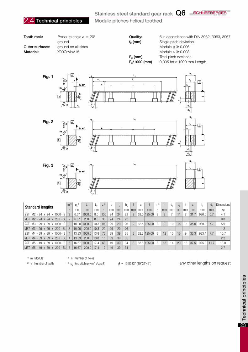
2.4 Technical principles Module pitches helical toothed
Tooth rack: Pressure angle α = 20º Quality: 6 in accordance with DIN 3962, 3963, 3967 ground fp (mm) Single pitch deviationOuter surfaces: groundonallsides Module≤3:0.006Material: X90CrMoV18 Module > 3: 0.008 Fp (mm) Total pitch deviation Fp/1000 (mm) 0,035 for a 1000 mm Length
Standard lengthsm 1) p
s 4) L
1L
2z 2) b h
kh
of a l n 3) h d
1d
2t a
1l1
d3
Dimensions
- mm mm mm - mm mm mm mm mm mm - mm mm mm mm mm mm mm kg
ZST M2 - 24 x 24 x 1000 - S 2 6.67 1000.0 8.5 150 24 24 22 2 62.5 125.00 8 8 7 11 7 31.7 936.6 5.7 4.1MST M2 - 24 x 24 x 200 -SL 2 6.67 200.0 8.5 30 24 24 22 0.8
ZST M3 - 29 x 29 x 1000 - S 3 10.00 1000.0 10.3 100 29 29 26 2 62.5 125.00 8 9 10 15 9 35.0 930.0 7.7 5.9MST M3 - 29 x 29 x 200 -SL 3 10.00 200.0 10.3 20 29 29 26 1.2
ZST M4 - 39 x 39 x 1000 - S 4 13.33 1000.0 13.8 75 39 39 35 3 62.5 125.00 8 12 10 15 9 33.3 933.4 7.7 10.7MST M4 - 39 x 39 x 200 -SL 4 13.33 200.0 13.8 15 39 39 35 2.2
ZST M5 - 49 x 39 x 1000 - S 5 16.67 1000.0 17.4 60 49 39 34 3 62.5 125.00 8 12 14 20 13 37.5 925.0 11.7 13.0MST M5 - 49 x 39 x 200 -SL 5 16.67 200.0 17.4 12 49 39 34 2.7
any other lengths on request
Fig. 1
Fig. 2
Fig. 3
Tech
nica
l pri
ncip
les
1) m Module 3) n Number of holes2) z Number of teeth 4) p
sEnd pitch (p
s=m*π/cos β) β = 19.5283° (19°31’42”)
Stainless steel standard gear rack Q6
24
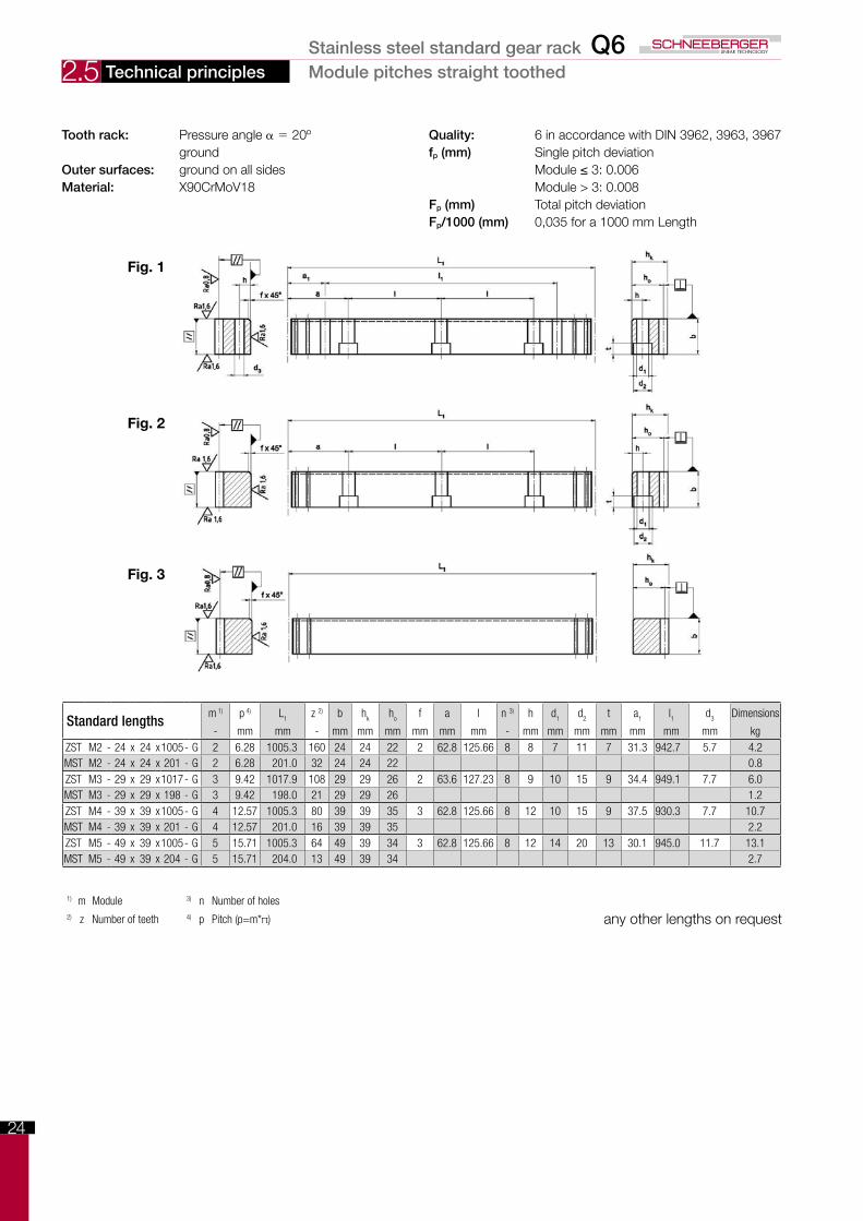
2.5 Technical principles Module pitches straight toothed
Tooth rack: Pressure angle α = 20º Quality: 6 in accordance with DIN 3962, 3963, 3967 ground fp (mm) Single pitch deviationOuter surfaces: groundonallsides Module≤3:0.006Material: X90CrMoV18 Module > 3: 0.008 Fp (mm) Total pitch deviation Fp/1000 (mm) 0,035 for a 1000 mm Length
Fig. 1
Fig. 2
Fig. 3
1) m Module 3) n Number of holes2) z Number of teeth 4) p Pitch (p=m*π) any other lengths on request
Standard lengthsm 1) p 4) L
1z 2) b h
kh
of a l n 3) h d
1d
2t a
1l1
d3
Dimensions
- mm mm - mm mm mm mm mm mm - mm mm mm mm mm mm mm kgZST M2 - 24 x 24 x1005- G 2 6.28 1005.3 160 24 24 22 2 62.8 125.66 8 8 7 11 7 31.3 942.7 5.7 4.2MST M2 - 24 x 24 x 201 - G 2 6.28 201.0 32 24 24 22 0.8ZST M3 - 29 x 29 x1017- G 3 9.42 1017.9 108 29 29 26 2 63.6 127.23 8 9 10 15 9 34.4 949.1 7.7 6.0MST M3 - 29 x 29 x 198 - G 3 9.42 198.0 21 29 29 26 1.2ZST M4 - 39 x 39 x1005- G 4 12.57 1005.3 80 39 39 35 3 62.8 125.66 8 12 10 15 9 37.5 930.3 7.7 10.7MST M4 - 39 x 39 x 201 - G 4 12.57 201.0 16 39 39 35 2.2ZST M5 - 49 x 39 x1005- G 5 15.71 1005.3 64 49 39 34 3 62.8 125.66 8 12 14 20 13 30.1 945.0 11.7 13.1MST M5 - 49 x 39 x 204 - G 5 15.71 204.0 13 49 39 34 2.7
Stainless steel standard gear rack Q6
25
2.6
Tech
nica
l pri
ncip
les
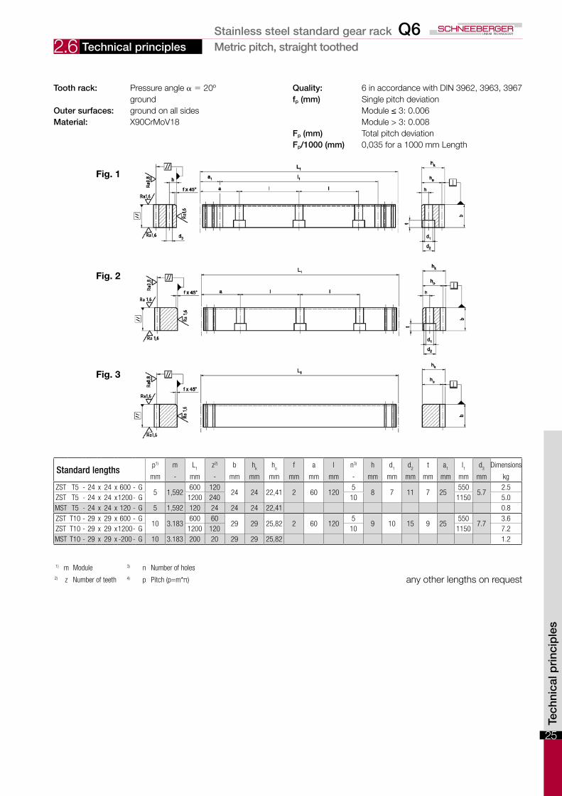
Technical principles Metric pitch, straight toothed
Tooth rack: Pressure angle α = 20º Quality: 6 in accordance with DIN 3962, 3963, 3967 ground fp (mm) Single pitch deviationOuter surfaces: groundonallsides Module≤3:0.006Material: X90CrMoV18 Module > 3: 0.008 Fp (mm) Total pitch deviation Fp/1000 (mm) 0,035 for a 1000 mm Length
Fig. 1
Fig. 2
Fig. 3
1) m Module 3) n Number of holes2) z Number of teeth 4) p Pitch (p=m*π) any other lengths on request
Standard lengthsp1) m L
1z2) b h
kh
of a l n3) h d
1d
2t a
1l1
d3
Dimensions
mm - mm - mm mm mm mm mm mm - mm mm mm mm mm mm mm kgZST T5 - 24 x 24 x 600 - G
5 1,592600 120
24 24 22,41 2 60 1205
8 7 11 7 25550
5.72.5
ZST T5 - 24 x 24 x1200- G 1200 240 10 1150 5.0MST T5 - 24 x 24 x 120 - G 5 1,592 120 24 24 24 22,41 0.8ZST T10 - 29 x 29 x 600 - G
10 3.183600 60
29 29 25,82 2 60 1205
9 10 15 9 25550
7.73.6
ZST T10 - 29 x 29 x1200- G 1200 120 10 1150 7.2MST T10 - 29 x 29 x -200 - G 10 3.183 200 20 29 29 25,82 1.2
Stainless steel standard gear rack Q6
26
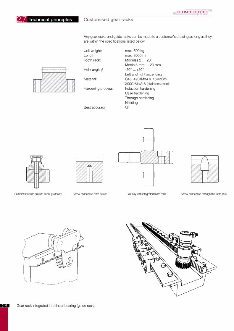
2.7 Technical principles Customised gear racks
Any gear racks and guide racks can be made to a customer's drawing as long as they are within the specifications listed below.
Unit weight: max. 500 kgLength: max. 3000 mmTooth rack: Modules 2 … 20 Metric 5 mm … 20 mmHelix angle β -30° …+30° Left and right ascendingMaterial: C45, 42CrMo4 V, 16MnCr5 X90CrMoV18 (stainless steel)Hardening process: Induction hardening Case hardening Through hardening NitridingBest accuracy: Q4
Gear rack integrated into linear bearing (guide rack)
Combination with profiled linear guideway Screw connection from below Box way with integrated tooth rack Screw connection through the tooth rack
27
3.1
Inst
alla
tion
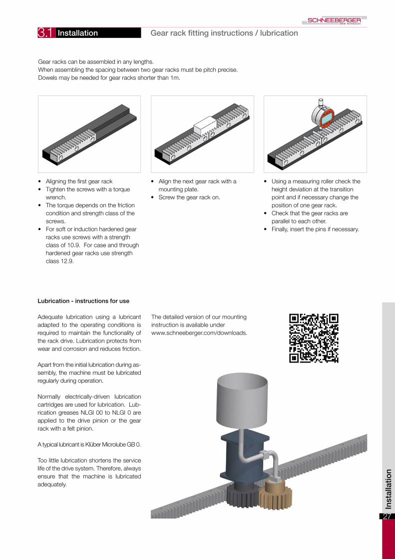
Installation Gearrackfittinginstructions/lubrication
Gear racks can be assembled in any lengths. When assembling the spacing between two gear racks must be pitch precise.Dowels may be needed for gear racks shorter than 1m.
• Aligning the first gear rack • Tighten the screws with a torque
wrench.• The torque depends on the friction
condition and strength class of the screws.
• For soft or induction hardened gear racks use screws with a strength class of 10.9. For case and through hardened gear racks use strength class 12.9.
• Align the next gear rack with a mounting plate.
• Screw the gear rack on.
• Using a measuring roller check the height deviation at the transition point and if necessary change the position of one gear rack.
• Check that the gear racks are parallel to each other.
• Finally, insert the pins if necessary.
Adequate lubrication using a lubricant adapted to the operating conditions is required to maintain the functionality of the rack drive. Lubrication protects from wear and corrosion and reduces friction.
Apart from the initial lubrication during as-sembly, the machine must be lubricated regularly during operation.
Normally electrically-driven lubrication cartridges are used for lubrication. Lub-rication greases NLGI 00 to NLGI 0 are applied to the drive pinion or the gear rack with a felt pinion.
A typical lubricant is Klüber Microlube GB 0.
Too little lubrication shortens the service life of the drive system. Therefore, always ensure that the machine is lubricated adequately.
Lubrication - instructions for use
The detailed version of our mounting instruction is available under www.schneeberger.com/downloads.
28
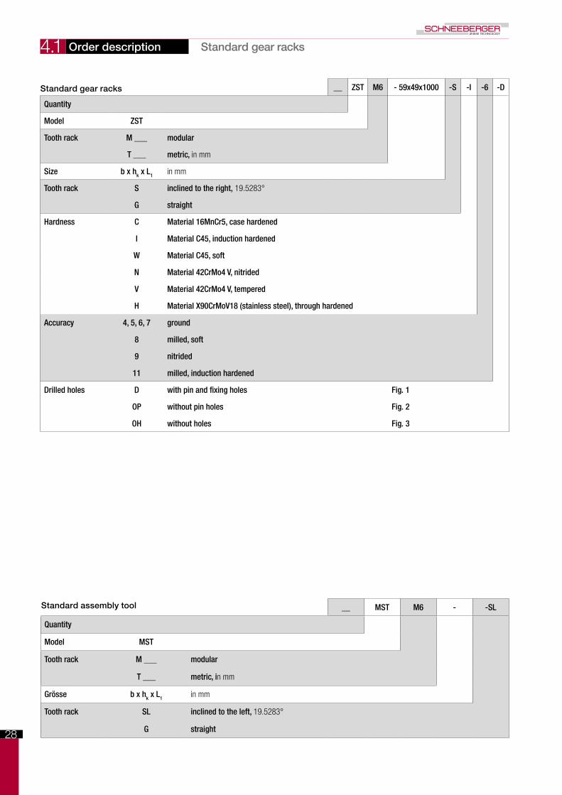
4.1 Order description Standard gear racks
Standard assembly tool __ MST M6 - -SL
Quantity
Model MST
Tooth rack M ___ modular
T ___ metric, in mm
Grösse b x hk x L1 in mm
Tooth rack SL inclined to the left, 19.5283°
G straight
Standard gear racks __ ZST M6 - 59x49x1000 -S -I -6 -D
Quantity
Model ZST
Tooth rack M ___ modular
T ___ metric, in mm
Size b x hk x L1 in mm
Tooth rack S inclined to the right, 19.5283°
G straight
Hardness C Material 16MnCr5, case hardened
I Material C45, induction hardened
W Material C45, soft
N Material 42CrMo4 V, nitrided
V Material 42CrMo4 V, tempered
H Material X90CrMoV18 (stainless steel), through hardened
Accuracy 4, 5, 6, 7 ground
8 milled, soft
9 nitrided
11 milled, induction hardened
Drilled holes D with pin and fixing holes Fig. 1
OP without pin holes Fig. 2
OH without holes Fig. 3
29
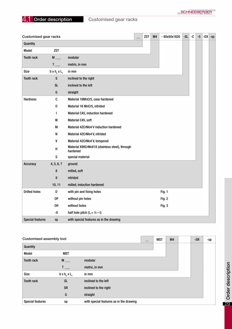
4.1 Order description Customised gear racks
Customised assembly tool __ MST M4 -SR -sp
Quantity
Model MST
Tooth rack M ___ modular
T ___ metric, in mm
Size b x hk x L1 in mm
Tooth rack SL inclined to the left
SR inclined to the right
G straight
Special features sp with special features as in the drawing
Customised gear racks __ ZST M4 - 60x50x1820 -SL -C -5 -DX -sp
Quantity
Model ZST
Tooth rack M ___ modular
T ___ metric, in mm
Size b x hk x L1 in mm
Tooth rack S inclined to the right
SL inclined to the left
G straight
Hardness C Material 16MnCr5, case hardened
O Material 16 MnCr5, nitrided
I Material C45, induction hardened
W Material C45, soft
M Material 42CrMo4 V induction hardened
N Material 42CrMo4 V, nitrided
V Material 42CrMo4 V, tempered
HMaterial X90CrMoV18 (stainless steel), through hardened
S special material
Accuracy 4, 5, 6, 7 ground
8 milled, soft
9 nitrided
10, 11 milled, induction hardened
Drilled holes D with pin and fixing holes Fig. 1
OP without pin holes Fig. 2
OH without holes Fig. 3
-X half hole pitch ( lx = ½ * l )
Special features sp with special features as in the drawing
Ord
er d
escr
iptio
n
30
5.1 5.1 Quality
Quality
All gear racks are manufactured on modern machine tools. The induction and through hardening is also done in-house.
It goes without saying that all SCHNEEBERGER production sites are ISO 9001 certi-fied.All process steps are self inspected by the machine operator. If required a measure-ment report is compiled on the quality of the gear rack.
The tooth rack profile complies with DIN 867, the tolerances for accuracy classes are based on DIN 3962, 3963 and 3967. The tooth rack is measured on a CNC measuring machine.
The special feature of the SCHNEEBERGER standard tooth rack is the tip chamfer. This reduces the risk of injury to a minimum.
Our concern is to provide the best industrial companies with the best products and services because that is the key to our customers' success.

Pro
du
ct c
atal
og
201
7 M
ON
OR
AIL
an
d A
MS
P
rofil
ed li
nea
r g
uid
eway
s an
d in
teg
rate
d m
easu
rin
g s
yste
ms
10.1
061/
04/0
717/
e
PROSPECTUSES
• COMPANY BROCHURE
• CUSTOMIZED BEARINGS
• GEAR RACKS
• LINEAR BEARINGS and RECIRCULATING UNITS
• MINERAL CASTING SCHNEEBERGER
• MINISLIDE MSQscale
• MINI-X MINIRAIL / MINISCALE PLUS / MINISLIDE
• MONORAIL and AMS profiled linear guideways with integrated measuring system
• MONORAIL and AMS application catalog
• POSITIONING SYSTEMS
• SLIDES
MONORAIL and AMS
Profiled linear guideways and integrated measuring systems
Product catalog 2017
www.schneeberger.com
www.schneeberger.com/contact
Recommended