Operating Manual
Gas fired igniter
ZA0 / ZDA0
© Hegwein GmbH
Am Boschwerk 7
70469 Stuttgart, Germany
Before first use, read the operating manual!
Tel.: +49 (0)711 13 57 88-0
Fax: +49 (0)711 13 57 88-5
E-Mail: [email protected]
www.hegwein.de
Status: 11-2018
Gas fired igniter ZA0 / ZDA0
Contents
- 2 - Status: 11-2018
1 General ....................................................... 3
1.1 Information on the operating manual ........... 3
1.2 Explanation of symbols ................................ 3
1.3 Liability disclaimer ....................................... 4
1.4 Copyright protection .................................... 5
1.5 Spare parts .................................................. 5
1.6 Warranty regulations ................................... 5
1.7 After-sales service ....................................... 6
2 Safety .......................................................... 7
2.1 Owner’s responsibility .................................. 7
2.2 Operating personnel .................................... 8
2.2.1 Requirements .............................................. 8
2.2.2 Unauthorized persons ................................. 9
2.3 Intended purpose of the equipment ............. 9
2.4 Personal protective gear ............................ 10
2.5 Special dangers ......................................... 11
2.6 Securing against unauthorized switching use ............................................................. 14
2.7 Response in case of danger or accident ... 15
3 Transport, packaging and storage ........ 16
3.1 Safety instructions for transport ................. 16
3.2 Transport inspection .................................. 16
3.3 Packaging .................................................. 17
3.4 Storage conditions ..................................... 17
4 Specifications .......................................... 18
4.1 Type designation with type key ................. 18
4.1.1 Type key of ionisation flame monitor ......... 19
4.2 Gas fired igniter ......................................... 19
4.3 Power head ............................................... 20
4.4 Dimensional drawing ................................. 22
4.5 Rating plate of gas fired igniter .................. 22
4.5.1 Rating plate of ionisation flame monitor .... 23
4.6 Service life ................................................. 24
5 Functional characteristics and structure ................................................... 25
5.1 Functional characteristics .......................... 25
5.2 Structure .................................................... 25
5.3 Ionisation flame monitor ............................ 26
5.3.1 Flame monitoring ....................................... 26
5.3.2 Safety time (flame failure detection time FFDT) ........................................................ 26
5.3.3 Test sockets .............................................. 27
5.4 Connections on the transformer part front panel .......................................................... 27
5.5 Gas and air adjusting components (accessories) ............................................. 28
5.6 Electrical wiring versions ........................... 29
6 Installation and initial commissioning .. 30
6.1 Safety ........................................................ 30
6.2 Installation and electrical connection ........ 32
6.3 Electrical function test ............................... 36
6.4 Setting the required air volume ................. 38
6.5 Setting the required gas volume ............... 39
6.6 Checking the setting result ........................ 42
7 Operation ................................................. 43
7.1 Safety ........................................................ 43
7.2 Operation................................................... 43
8 Maintenance ............................................ 44
8.1 Safety ........................................................ 44
8.2 Maintenance, general ................................ 44
8.3 Conditions for maintenance work .............. 45
8.3.1 Exchanging the outer tube ........................ 46
8.3.2 Exchanging the power head...................... 47
8.3.3 Exchanging the ionisation flame monitor .. 47
8.3.4 Exchanging the final electrode support ring ............................................................ 48
8.3.5 Exchanging the intermediate support rings ........................................................... 49
8.4 Actions following completed maintenance work ........................................................... 49
9 Troubleshooting ...................................... 50
9.1 Safety ........................................................ 50
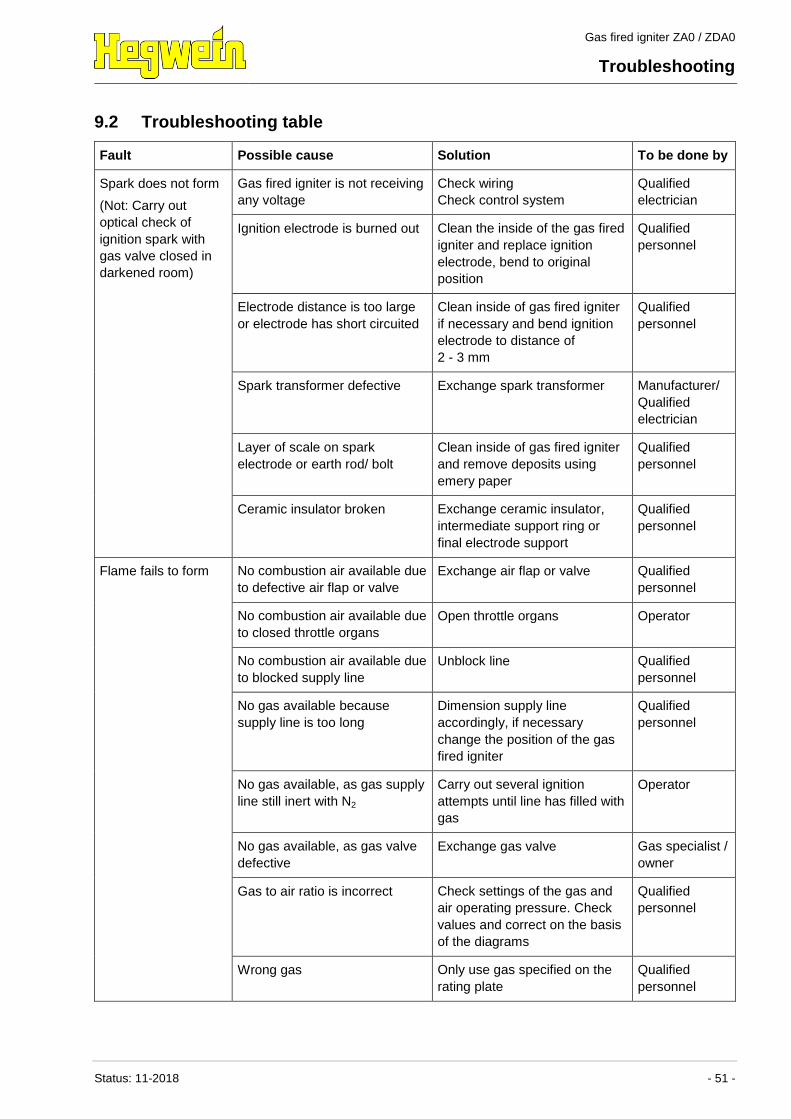
9.2 Troubleshooting table ................................ 51
10 Dismantling / Disposal ............................ 54
10.1 Safety ........................................................ 54
10.2 Dismantling................................................ 54
10.3 Disposal..................................................... 55
11 Spare parts list ........................................ 56
11.1 Spare and wearing parts ........................... 56
12 Annex ....................................................... 58
12.1 EU type examination certificate ................ 58
12.2 EU Declaration of conformity .................... 60
Gas fired igniter ZA0 / ZDA0
General
Status: 11-2018 - 3 -
1 General
1.1 Information on the operating manual
This operating manual provides important information on working
with the gas fired igniter. Safe working can only be ensured by
adhering to all the safety remarks and instructions provided.
In addition, the locally applicable accident prevention laws and
general safety regulations must be followed.
Read the operating manual carefully before using the gas fired
igniter the first time. These instructions form an integral part of the
product and must be kept near the equipment at all times within
easy reach for personnel.
When the gas fired igniter is transferred on to third parties, it must
always be accompanied by the operating instructions.
The illustrations in this operating manual are intended to aid
understanding of the content. They are not necessarily true to
scale and may differ slightly in some details from the actual
configuration of the gas fired igniter.
1.2 Explanation of symbols
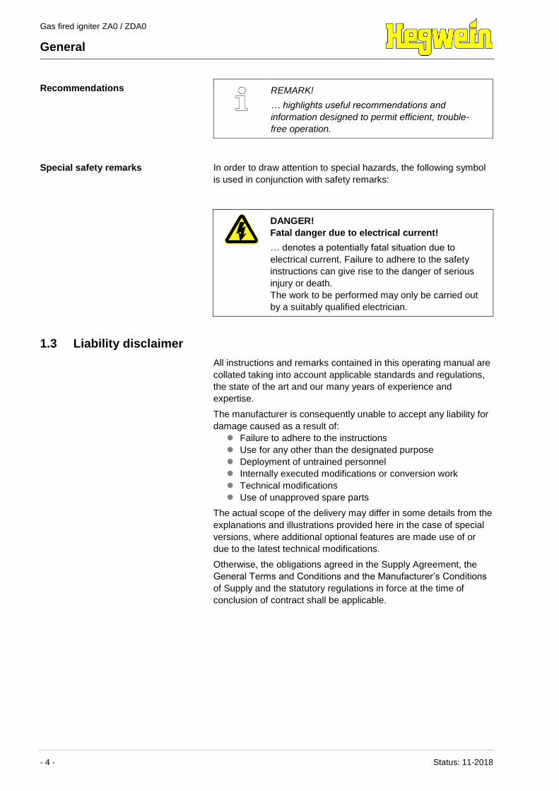
Warning instructions Warning instructions are indicated in this operating manual by
symbols. The remarks are introduced by the use of signal words
which indicate the degree of severity of the hazard.
The instructions must be adhered to without fail and acted upon
prudently in order to prevent accidents, personal injury or material
damage.
DANGER!
… denotes a hazardous situation which results in
death or serious injury unless prevented.
WARNING!
… denotes a hazardous situation which could result
in death or serious injury unless prevented.
CAUTION!
… denotes a hazardous situation which could result
in minor or slight injury unless prevented.
NOTE!
… denotes a hazardous situation which could result
in material damage unless prevented.
Gas fired igniter ZA0 / ZDA0
General
- 4 - Status: 11-2018
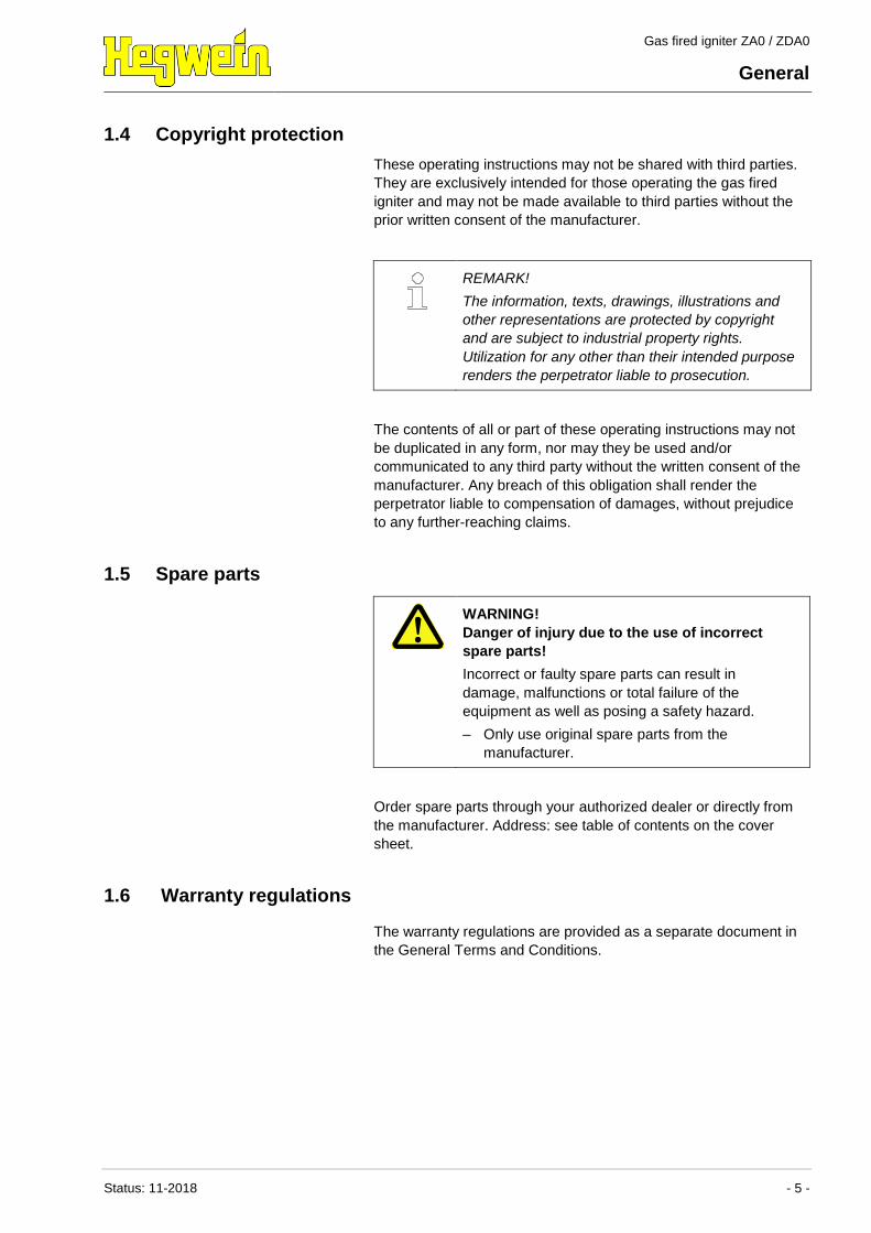
Recommendations
REMARK!
… highlights useful recommendations and
information designed to permit efficient, trouble-
free operation.
Special safety remarks In order to draw attention to special hazards, the following symbol
is used in conjunction with safety remarks:
DANGER!
Fatal danger due to electrical current!
… denotes a potentially fatal situation due to
electrical current. Failure to adhere to the safety
instructions can give rise to the danger of serious
injury or death.
The work to be performed may only be carried out
by a suitably qualified electrician.
1.3 Liability disclaimer
All instructions and remarks contained in this operating manual are
collated taking into account applicable standards and regulations,
the state of the art and our many years of experience and
expertise.
The manufacturer is consequently unable to accept any liability for
damage caused as a result of:
Failure to adhere to the instructions
Use for any other than the designated purpose
Deployment of untrained personnel
Internally executed modifications or conversion work
Technical modifications
Use of unapproved spare parts
The actual scope of the delivery may differ in some details from the
explanations and illustrations provided here in the case of special
versions, where additional optional features are made use of or
due to the latest technical modifications.
Otherwise, the obligations agreed in the Supply Agreement, the
General Terms and Conditions and the Manufacturer’s Conditions
of Supply and the statutory regulations in force at the time of
conclusion of contract shall be applicable.
Gas fired igniter ZA0 / ZDA0
General
Status: 11-2018 - 5 -
1.4 Copyright protection
These operating instructions may not be shared with third parties.
They are exclusively intended for those operating the gas fired
igniter and may not be made available to third parties without the
prior written consent of the manufacturer.
REMARK!
The information, texts, drawings, illustrations and
other representations are protected by copyright
and are subject to industrial property rights.
Utilization for any other than their intended purpose
renders the perpetrator liable to prosecution.
The contents of all or part of these operating instructions may not
be duplicated in any form, nor may they be used and/or
communicated to any third party without the written consent of the
manufacturer. Any breach of this obligation shall render the
perpetrator liable to compensation of damages, without prejudice
to any further-reaching claims.
1.5 Spare parts
WARNING!
Danger of injury due to the use of incorrect
spare parts!
Incorrect or faulty spare parts can result in
damage, malfunctions or total failure of the
equipment as well as posing a safety hazard.
– Only use original spare parts from the
manufacturer.
Order spare parts through your authorized dealer or directly from
the manufacturer. Address: see table of contents on the cover
sheet.
1.6 Warranty regulations
The warranty regulations are provided as a separate document in
the General Terms and Conditions.
Gas fired igniter ZA0 / ZDA0
General
- 6 - Status: 11-2018
1.7 After-sales service
For any technical information, consult our after-sales service.
Information can be obtained at any time by phone, fax, e-mail or
Internet. For the manufacturer’s address, see the cover sheet on
the table of contents.
Our employees are always open to feedback and comments
related to all of our products which could be of use in the continual
and improvement of our products.
Gas fired igniter ZA0 / ZDA0
Safety
Status: 11-2018 - 7 -
2 Safety
This section provides an overview of all important safety aspects
for optimum protection of personnel as well as safe, trouble free
operation.
Failure to observe the operating instructions and safety remarks
contained in this manual can cause serious injury.
2.1 Owner’s responsibility
As the gas fired igniter is used commercially, the owner of the gas
fired igniter is obliged to adhere to occupational safety regulations
as well as any other applicable directives, legislation and
standards.
Alongside the occupational safety remarks contained in these
operating instructions, the safety, environmental and accident
prevention regulations governing the field of application of the gas
fired igniter must be adhered to, whereby the following regulations
in particular apply:
The owner must be aware of the valid occupational safety
regulations and also determine any additional potential hazards
arising as a result of the specific working conditions applicable
at the location in which the igniter is used, by performing a risk
assessment. This must be implemented in the form of operating
instructions governing operation of the gas fired igniter.
The owner must test, throughout the service life of the gas fired
igniter, whether the operating instructions drawn up by him still
correspond with the latest revision of the relevant rules and
regulations, and must update these where applicable.
The owner must clearly regulate and define fields of
responsibility for installation, operation, maintenance and
cleaning.
The owner must ensure that all employees involved in working
with the gas fired igniter have read and understood the
operating instructions.
Furthermore, the owner must provide personnel training at
regular intervals and inform staff of potential hazards.
As the owner is also responsible for ensuring that the gas fired
igniter is always in good technical working order the following
requirements additionally apply:
The owner must ensure that maintenance work is performed
regularly.
The owner must regularly check that all safety devices are fully
functional and complete.
The owner must provide the necessary protective gear for
personnel.
Gas fired igniter ZA0 / ZDA0
Safety
- 8 - Status: 11-2018
2.2 Operating personnel
2.2.1 Requirements
WARNING!
Danger of injury due to insufficient qualification
Incorrect handling of the equipment can result in
severe personal injury and material damage.
– Only allow activities to be performed by suitably
qualified specialist personnel.
The following qualifications are required for the various fields of
activity:
Qualified personnel
are capable on the basis of their specialist training, knowledge
and experience as well as their knowledge of the applicable
regulations of executing the work assigned to them and of
independently recognizing possible hazards.
Electrical specialists
are capable on the basis of their specialist training, knowledge
and experience as well as their knowledge of the applicable
regulations of working on electrical installations and of
independently recognizing possible hazards.
Electrical specialists have received training specifically for the
work environment in which they are employed and are familiar
with the relevant standards and regulations.
Gas specialists
are capable on the basis of their specialist training, knowledge
and experience as well as their knowledge of the applicable
regulations of working on gas installations and of independently
recognizing possible hazards.
Gas specialists have received training specifically for the work
environment in which they are employed and are familiar with
the relevant standards and regulations.
Only persons who may be expected to perform their task reliably
may be authorized to use the equipment. Persons whose reaction
capacity is impaired, for example due to drugs, alcohol or medicine
use, may not be authorized.
When selecting suitable personnel, observe the age and
profession-specific regulations applicable at the place of use.
Gas fired igniter ZA0 / ZDA0
Safety
Status: 11-2018 - 9 -
2.2.2 Unauthorized persons
WARNING! Danger for unauthorized persons!
Persons who do not comply with the requirements
described here are not aware of the dangers
inherent in the work area.
– Keep unauthorized persons away from the work
area.
– In case of doubt, approach the person in
question and direct them out of the work area.
– Interrupt work for as long as any unauthorized
person remains in the work area.
2.3 Intended purpose of the equipment
The gas fired igniter is exclusively designed to perform the
intended purpose described here.
The gas fired igniter is a piece of equipment that has to be
integrated into a gas-consuming installation. It must not be
operated without an overriding safety control system.
It is designed for the sole purpose off lighting and
supporting any gas-, oil- or solid fuel fired burner of medium
heat release in industrial furnaces, thermo-processing
plants and boilers.
WARNING!
Danger due to use not in accordance with the
intended purpose!
Any application beyond and/or not in accordance
with the intended purpose of the gas fired igniter
can result in the occurrence of hazardous
situations.
– Only operate the gas fired igniter when in a
mounted condition. Ensure that the combustion
points created by the flame are fitted with a
suitable extraction facility over the exposed flue
gas channel throughout the plant.
– Only operate the gas fired igniter according to
the specifications indicated on the rating plate.
Otherwise, potential danger of personal or
material damage can arise.
– Adhere to all the instructions provided in this
operating manual without fail.
The manufacturer can not be held liable for physical or material
harm caused by misuse of equipment or use for anything other
than its intended purpose.
Gas fired igniter ZA0 / ZDA0
Safety
- 10 - Status: 11-2018
2.4 Personal protective gear
Personal protective gear must be worn while working with the
equipment in order to minimize potential health hazards.
Wear the protective gear necessary for performance of the
relevant task at all times while working.
Observe all signs relating to personal protective gear in the
work area.
To be worn at all times Wear the following for the performance of all work:
Protective work clothing
This comprises tight-fitting work clothes which are resistant to
tearing, have tight-fitting sleeves and no projecting parts. This is
required primarily to protect against burns.
Safety shoes
To protect the feet against heavy falling articles and to prevent
slipping on floors.
Protection helmet
Protection helmets protect the head from falling parts, swinging
loads or bumping it against stationary equipment.
To be worn for special types of
work
When performing special types of work, special safety equipment
is required. This is covered in depth in the individual chapters of
this instruction manual. These types of special protective gear are
described in the following:
Face protection
To protect one’s eyes and face from flames, sparks or embers as
well as hot particles or flue gases.
Protective gloves
To protect one’s hands from rubbing, chafing, puncturing or deeper
injuries and from contact with hot surfaces.
Gas fired igniter ZA0 / ZDA0
Safety
Status: 11-2018 - 11 -
2.5 Special dangers
Remaining dangers are listed in the section below.
The remarks provided here and the safety instructions in the
subsequent chapters of this operating manual must be observed in
order to reduce the possible risk to health and prevent the
occurrence of dangerous situations.
Incorrect transport
WARNING!
Danger of injury as a result of incorrect
transport!
In the case of incorrect transport, considerable
material damage can occur.
– Note the intrinsic weight of the gas fired igniter
or the components. If necessary, use suitable
hoisting gear.
– From an outer tube length of 3 m use several
lashing points or a suitable hoisting gear with
supports.
– Please mind the centre of gravity.
– Secure the gas fired igniter from dropping down
or falling over.
– Do not stand under the load while lifting or
lowering it and stay out of the danger zone.
Gas fired igniter ZA0 / ZDA0
Safety
- 12 - Status: 11-2018
Electrical current
DANGER!
Danger to life due to electrical current!
When touching with current conducting parts, there
is a danger to life. Damage to the insulation or
individual components can have potentially life-
threatening consequences.
– In the event of damage to the insulation of the
power supply, switch off immediately and
arrange for repairs to be carried out.
– Work on the electrical system may only be
carried out by suitably qualified electricians.
– Before starting work, switch off the power
supply and make sure it cannot be inadvertently
switched back on. Observe the 5 safety rules:
– De-energise.
– Secure against reconnection.
– Ascertain de-energised condition.
– Earth and short-circuit.
– Cover or block off adjacent live parts.
– Never bypass or decommission fuses. When
changing fuses, adhere to the correct amperage
and the correct characteristics.
– Only connect the gas fired igniter and the
integrated ionisation flame monitor to the
permitted operating voltage / load according to
the technical data.
– The ionisation flame monitor is only provided as
a built-in appliance in the gas fired igniter.
– The operator/installer is responsible for
adherence to the permitted environmental
conditions and/or ambient atmosphere in
accordance with the technical data.
– Keep moisture away from live components. This
can create a short circuit.
Electrostatic charge (ESD)
CAUTION!
Damage of electronic components due to
electrostatic discharge (ESD)!
Electronic components become steadily smaller
and more complex. This also increases the
susceptibility to electrostatic discharging.
– Take measures to protect the components
against electrostatic discharge.
– Take measures to prevent static charging of the
human body.
Gas fired igniter ZA0 / ZDA0
Safety
Status: 11-2018 - 13 -
Highly inflammable materials
WARNING!
Danger of burns due to flammable materials!
Highly flammable materials, liquids or gases can
catch fire and cause serious to fatal injuries.
– Do not smoke in the danger area and in the
close vicinity. Do not use any naked flames or
ignition sources.
– Keep a fire extinguisher on hand.
– Report suspicious substances, liquids or gases
immediately to the responsible officer.
– In case of fire, stop work immediately. Leave
the danger area until the all-clear is given.
Hot surfaces
CAUTION!
Danger of burns due to hot surfaces!
Contact with hot components can cause burns.
– When carrying out any work near hot
components, always wear protective work
clothing and safety gloves.
– Before performing any work, ensure that all
components have cooled to ambient
temperature.
Sharp edges and pointed corners
CAUTION!
Danger of injury on edges and corners!
Sharp edges and pointed corners can cause
chafing of the skin and cuts.
– Take particular care when performing work near
to sharp edges and pointed corners.
– In unsure, wear safety gloves.
Special environmental influences
NOTE!
Danger of damage due to special
environmental influences!
Vibrations affecting the gas fired igniter or welding
work performed in the area of the gas fired igniter
can result in damage.
– In order to prevent damage to the gas fired
igniter, it must not be exposed to any vibrations.
– When carrying out any welding work in the area
of the gas fired igniter, it must be electrically
disconnected and removed.
– Before welding work on the outer tube of the
gas fired igniter can be carried out, this must
first be disconnected from the power head.
Gas fired igniter ZA0 / ZDA0
Safety
- 14 - Status: 11-2018
2.6 Securing against unauthorized switching use
DANGER!
Risk of fatal injury due to unauthorized use!
When working in the danger area, there is a risk
that the energy supply could be switched on by an
unauthorized person. This creates a potentially
fatal hazard for persons working in the danger
area.
– Observe the instructions provided on securing
against unauthorized switching back on in the
chapters of this operating manual.
– Always observe the procedure described below
to secure against unauthorized switching back
on.
Switch safeguarded by lock
on: …….. at ……hours
DO NOT SWITCH ON
The lock may only be removed
by: …………………
once steps have been taken to ensure
that no persons are located in the
danger area.
Securing against unauthorized use
1. Switch off the power supply.
2. If possible, secure the switch with a lock and attach a sign in
an easily visible location at the switch.
3. Have the key looked after by the employee named on the
sign.
Switched off
on: …….. at ……hours
DO NOT SWITCH ON
The lock may only be removed
by: …………………
once steps have been taken to ensure
that no persons are located in the
danger area..
4. Should it not be possible to secure a switch using a lock, set
up a sign.
5. Once all the work has been carried out, ensure that there are
no longer any persons located in the danger area.
6. Ensure that all safety devices are installed and are fully
functional.
7. Only then may the sign be removed.
Gas fired igniter ZA0 / ZDA0
Safety
Status: 11-2018 - 15 -
2.7 Response in case of danger or accident
Preventive actions Always be prepared for accidents and for fires!
Keep first aid equipment (first aid kit, blankets etc.) and a fire
extinguisher on hand.
Familiarize personnel with accident alarm, first aid and rescue
facilities.
Ensure that access paths for emergency vehicles are kept
unobstructed.
In case of accident: React correctly Initiate first aid measures.
Evacuate any persons located in the danger area.
Inform those responsible at the incident location.
Alert the emergency medical / fire services.
Clear access paths for emergency vehicles.
Gas fired igniter ZA0 / ZDA0
Transport, packaging and storage
- 16 - Status: 11-2018
3 Transport, packaging and storage
3.1 Safety instructions for transport
Incorrect transport
WARNING!
Danger of injury as a result of incorrect
transport!
In the case of incorrect transport, considerable
material damage can occur.
– When unloading packaged items on delivery,
and when transporting within the premises, take
extreme care and observe the symbols and
instructions on the packaging.
– Depending on the length of the product and the
scope of delivery suitable lifting equipment
should be used for unloading. The load capacity
of the lifting equipment should exceed the total
weight of the delivery.
– Please mind the centre of gravity.
– Only use the provided lashing points.
– Do not stand under the load while lifting or
lowering it and stay out of the danger zone.
REMARK!
Extreme vibration or shock may cause damage to
electrical components.
3.2 Transport inspection
Check the delivery on receipt without delay for completeness and
transport damage.
In the case of externally recognizable transport damage, report the
damage immediately, adopting the following procedure:
Only conditionally accept the delivery.
Note the extent of the damage on the transport documents or
on the shipping agent’s delivery note.
Initiate a complaint.
Concealed transport damage must be reported within seven days.
REMARK!
Report any defect immediately it is noticed. Claims
for damages can only be asserted within the
applicable deadlines for the filing of complaints.
Gas fired igniter ZA0 / ZDA0
Transport, packaging and storage
Status: 11-2018 - 17 -
3.3 Packaging
Packaging The individual products are packaged in accordance with the
transport conditions expected for the consignment. Exclusively
environmentally friendly materials are used for the packaging.
The packaging should protect the individual components from
transport damage, corrosion and other damage up until such time
as they are assembled. For this reason, do not destroy the
packaging and only remove it shortly before assembly.
Handling packaging materials If no outline agreement has been reached for packaging, separate
the materials according to type and size, and send for re-use or
recycling.
NOTE!
Environmental damage due to incorrect
disposal!
Packaging materials are valuable raw materials
and in many cases can be reused or usefully
processed and recycled.
– Ensure environmentally responsible disposal of
packaging materials.
– Observe locally applicable disposal regulations.
3.4 Storage conditions
Storage Store the gas fired igniter and the spare parts under the following
conditions:
Never keep outdoors.
Store in dry, dust-free conditions.
Do not expose to any corrosiv substances.
Avoid any drop in temperature below the dew point.
Protect the gas fired igniter from mechanical damage.
Storage temperature: 0 °C to 60 °C
Relative humidity: max. 60 %
When storing for longer than 3 months, regularly check the
condition of all parts and the packaging. If necessary refresh or
replace the conservation.
REMARK!
The packaging units may come with storage
instructions applicable in addition to the
requirements outlined here. These must be
adhered to.
Gas fired igniter ZA0 / ZDA0
Specifications
- 18 - Status: 11-2018
4 Specifications
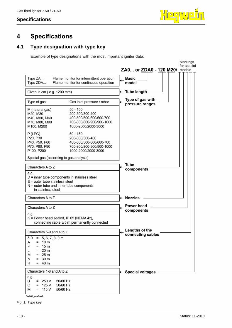
4.1 Type designation with type key
Example of type designations with the most important igniter data:
Fig. 1: Type key
Gas fired igniter ZA0 / ZDA0
Specifications
Status: 11-2018 - 19 -
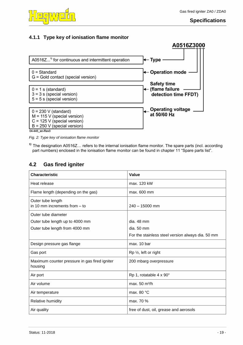
4.1.1 Type key of ionisation flame monitor
Fig. 2: Type key of ionisation flame monitor
1) The designation A0516Z… refers to the internal ionisation flame monitor. The spare parts (incl. according
part numbers) enclosed in the ionisation flame monitor can be found in chapter 11 “Spare parts list”.
4.2 Gas fired igniter
Characteristic Value
Heat release max. 120 kW
Flame length (depending on the gas) max. 600 mm
Outer tube length
in 10 mm increments from – to
240 – 15000 mm
Outer tube diameter
Outer tube length up to 4000 mm
Outer tube length from 4000 mm
dia. 48 mm
dia. 50 mm
For the stainless steel version always dia. 50 mm
Design pressure gas flange max. 10 bar
Gas port Rp ½, left or right
Maximum counter pressure in gas fired igniter
housing
200 mbarg overpressure
Air port Rp 1, rotatable 4 x 90°
Air volume max. 50 m³/h
Air temperature max. 80 °C
Relative humidity max. 70 %
Air quality free of dust, oil, grease and aerosols
Gas fired igniter ZA0 / ZDA0
Specifications
- 20 - Status: 11-2018
Characteristic Value
Air coefficient
The remaining air volume must be made available
in the combustion chamber.
0.3 – 0.5
Maximum ambient temperature of the outer tube see chapter “Installation and electrical connection”
Total weight (depending on scope of delivery) approx. 3.5 kg power head with mounting flange +
approx. 3.5 kg/m (length of outer tube in cm, as
indicated in the rating plate)
Total dimensions (depending on scope of delivery) Length of power head with mounting flange (see
dimensional drawing in section 4.4) + outer tube
length (in cm, as indicated in the rating plate)
4.3 Power head
Characteristic Value
Supply voltage of ionisation flame monitor 230 V AC +10%/-15%, 50/60 Hz (standard)
or in accordance with rating plate
Supply voltage of spark transformer
Primary:
230 V AC, 50/60 Hz (standard)
or in accordance with rating plate
Secondary:
5 kV against ground
Protection rating IP 54 (standard) or
IP 65 (special version)
Connection type
Standard version, IP 54, with plug connection,
type ZA..., ZDA...
Electrical connecting plug (10-pin) with 2 cable
glands (M20x1.5) for cable diameter 7 – 13 mm;
Line-/screw connection 0.5 – 2.5 mm2
(2.5 mm2 only without core cable ends)
Connection type
Special version, IP 65, with 7-core control cable,
sealed ionisation flame monitor connection,
type ZA…
Permanently sealed control cable,
wire gauge 1 mm2,
cable diameter approx. 9.5 mm
Connection type
Special version, IP 65, with 12-core control cable,
sealed ionisation flame monitor connection,
type ZDA...
Permanently sealed control cable,
wire gauge 1 mm2,
cable diameter approx. 12.1 mm
Power consumption
Spark transformer:
100 VA (fusing 2 A slow blowing, to be fused
externally)
Ionisation flame monitor:
10 VA (fusing 2 A slow blowing, to be fused
externally)
Gas fired igniter ZA0 / ZDA0
Specifications
Status: 11-2018 - 21 -
Characteristic Value
Duty cycle Spark transformer:
actuation via control unit
15 % duty cycle (cycle duration 3 min. = 100 %)
Primary thermal winding protection.
Ionisation flame monitor: 100 % duty cycle
Ambient temperature - 30 °C to + 60 °C (condensation must be avoided)
Ambient temperature (special version) - 30 °C to + 80 °C (condensation must be avoided)
Interconnection With Hegwein control units (see chapter “Functional
characteristics and structure”)
Contact load with ZDA configuration at terminals 4,
5 and 6
SPDT contact (flame relay),
max. 250 V AC, 1A, cos φ 1 (ohmic), fusing 1A
quick blowing on front plate 1) 2)
Safety time (flame failure detection time FFDT)
Switching threshold
≤ 1 s (optional 3 or 5 s)
≥ 1 µA
Flame signal to measuring sockets 0 - 25 µA (measurement range max. 50 µA)
Mech. service life of ionisation flame monitor ≥ 1 x 10⁶ switching cycles
Electr. service life of ionisation flame monitor 250.000 switching cycles
1) Terminal 5: Flame OFF signal, terminal 6: Flame ON signal
2) The special version with gold contacts is exclusively intended for connecting low power outputs (< 1 VA).
Gas fired igniter ZA0 / ZDA0
Specifications
- 22 - Status: 11-2018
4.4 Dimensional drawing
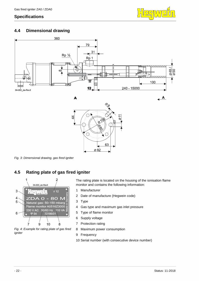
Fig. 3: Dimensional drawing, gas fired igniter
4.5 Rating plate of gas fired igniter
Fig. 4: Example for rating plate of gas fired
igniter
The rating plate is located on the housing of the ionisation flame
monitor and contains the following information:
1 Manufacturer
2 Date of manufacture (Hegwein code)
3 Type
4 Gas type and maximum gas inlet pressure
5 Type of flame monitor
6 Supply voltage
7 Protection rating
8 Maximum power consumption
9 Frequency
10 Serial number (with consecutive device number)
Gas fired igniter ZA0 / ZDA0
Specifications
Status: 11-2018 - 23 -
4.5.1 Rating plate of ionisation flame monitor
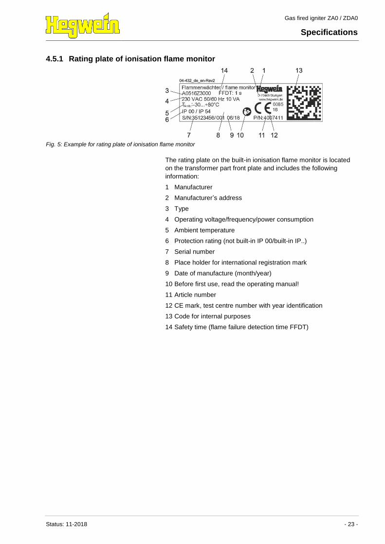
Fig. 5: Example for rating plate of ionisation flame monitor
The rating plate on the built-in ionisation flame monitor is located
on the transformer part front plate and includes the following
information:
1 Manufacturer
2 Manufacturer’s address
3 Type
4 Operating voltage/frequency/power consumption
5 Ambient temperature
6 Protection rating (not built-in IP 00/built-in IP..)
7 Serial number
8 Place holder for international registration mark
9 Date of manufacture (month/year)
10 Before first use, read the operating manual!
11 Article number
12 CE mark, test centre number with year identification
13 Code for internal purposes
14 Safety time (flame failure detection time FFDT)
Gas fired igniter ZA0 / ZDA0
Specifications
- 24 - Status: 11-2018
4.6 Service life
NOTE!
This product does not have an unlimited
service life!
It has been designed for a maximum service life at
nominal load, the mounted ionisation flame monitor
is type approved. In applications involving 50
switching processes per day, this service life is set
at around 10 years. This period can be
substantially reduced in the event of increased
stress (temperature, vibrations, dirt etc.).
– System operators and owners must take the
steps to ensure that regular safety checks are
performed depending on the actually occurring
degree of stress.
– Exchange the gas fired igniter after it has
exceeded the specified service life. After expiry
of the maximum operating period, functional
defects can occur more frequently.
– Check wearing parts independently of actual
stress levels and exchange if required.
Life of the ionisation flame
monitors (based on EN 298)
Specification Value Unit
Maximum operating life 250,000 Switch
cycles
Gas fired igniter ZA0 / ZDA0
Functional characteristics and structure
Status: 11-2018 - 25 -
5 Functional characteristics and structure
5.1 Functional characteristics
The gas fired igniter is a device whose flame is designed to ignite
and support a main burner. A high voltage is generated from an
input voltage (mains voltage), which generates an ignition spark at
the gas nozzle. The resulting flame generates a flame signal via
the flame rod. This flame signal is amplified in the ionisation flame
monitor and enables the main burner.
5.2 Structure
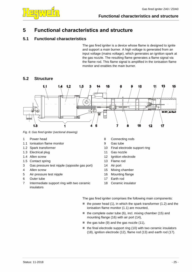
Fig. 6: Gas fired igniter (sectional drawing)
1 Power head
1.1 Ionisation flame monitor
1.2 Spark transformer
1.3 Electrical plug
1.4 Allen screw
1.5 Contact spring
3 Gas pressure test nipple (opposite gas port)
4 Allen screw
5 Air pressure test nipple
6 Outer tube
7 Intermediate support ring with two ceramic
insulators
8 Connecting rods
9 Gas tube
10 Final electrode support ring
11 Gas nozzle
12 Ignition electrode
13 Flame rod
14 Air port
15 Mixing chamber
16 Mounting flange
17 Earth rod
18 Ceramic insulator
The gas fired igniter comprises the following main components:
the power head (1), in which the spark transformer (1.2) and the
ionisation flame monitor (1.1) are mounted,
the complete outer tube (6), incl. mixing chamber (15) and
mounting flange (16) with air port (14),
the gas tube (9) and the gas nozzle (11),
the final electrode support ring (10) with two ceramic insulators
(18), ignition electrode (12), flame rod (13) and earth rod (17).
Gas fired igniter ZA0 / ZDA0
Functional characteristics and structure
- 26 - Status: 11-2018
The outer tube (6) is screwed to the power head (1) and can be
removed or depending on the position of the air supply pipe can be
turned by 90°.
The gas port can be on the left or right. The unused opening is
sealed off by a sealing screw, into which a gas pressure testing
nipple (3) is screwed.
The final electrode support ring (10) is fastened on the end of the
gas tube (9).
The flame rod (13) and the ignition electrode (12) are extended by
connecting rods (8). These connecting rods are guided through the
floor of the transformer housing and are supported around every
300 mm by intermediate support rings (7).
5.3 Ionisation flame monitor
Depending on the measured ionisation current (flame established)
of gas fired igniter, the ionisation flame monitor switches both
flame signal contacts. The yellow LED integrated into the
transformer part front panel is illuminated as long as there is a
flame signal.
5.3.1 Flame monitoring
The flame is monitored by the flame rod, which must immerse in
the direction of the flame. Alternating voltage is applied to this
flame rod. The burning flame creates an electrically conductive
connection to the igniter earth and at the same time acts as a
rectifier for the ionisation current. This direct current signal is
measured and amplified in the ionisation flame monitor. The
enforced flame signal activates the flame relay with one SPDT
contact (only series ZDA…).
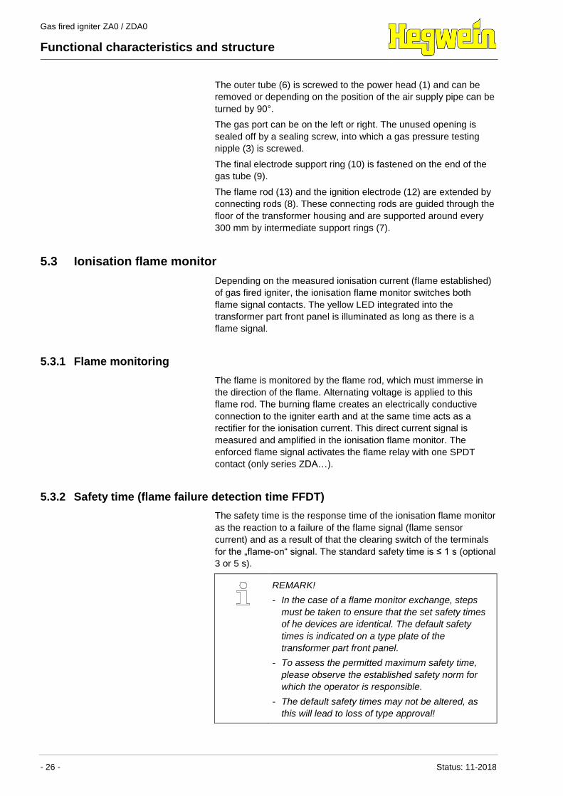
5.3.2 Safety time (flame failure detection time FFDT)
The safety time is the response time of the ionisation flame monitor
as the reaction to a failure of the flame signal (flame sensor
current) and as a result of that the clearing switch of the terminals
for the „flame-on“ signal. The standard safety time is ≤ 1 s (optional
3 or 5 s).
REMARK!
- In the case of a flame monitor exchange, steps
must be taken to ensure that the set safety times
of he devices are identical. The default safety
times is indicated on a type plate of the
transformer part front panel.
- To assess the permitted maximum safety time,
please observe the established safety norm for
which the operator is responsible.
- The default safety times may not be altered, as
this will lead to loss of type approval!
Gas fired igniter ZA0 / ZDA0
Functional characteristics and structure
Status: 11-2018 - 27 -
5.3.3 Test sockets
Thanks to the test sockets integrated into the transformer part front
panel, it is possible to measure the ionisation current without
interruptions. A customary amperemeter with a measurement
range from 0 - 50 μA DC shall be used for the measurement.
The test sockets are designed for short-time measurements for
flame signal optimisation only. A permanent connection of
measurement devices is not permissible.
Anschl üsse
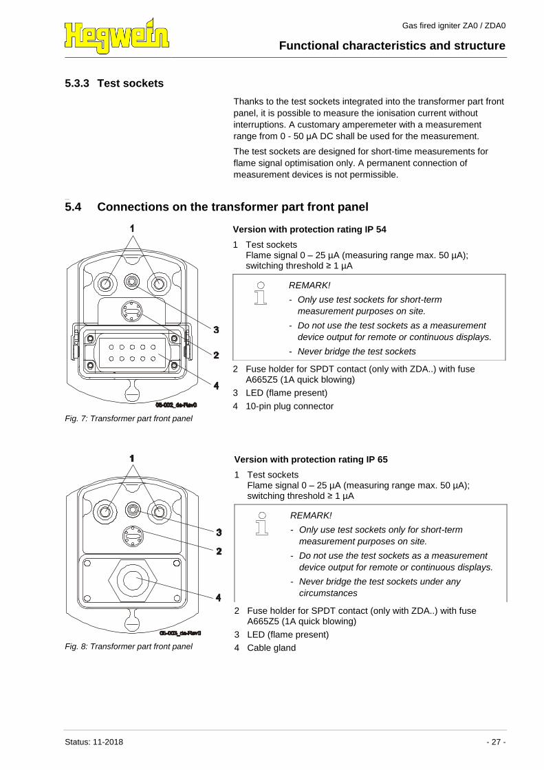
5.4 Connections on the transformer part front panel
Fig. 7: Transformer part front panel
Version with protection rating IP 54
1 Test sockets Flame signal 0 – 25 µA (measuring range max. 50 µA);
switching threshold ≥ 1 µA
2 Fuse holder for SPDT contact (only with ZDA..) with fuse A665Z5 (1A quick blowing)
3 LED (flame present)
4 10-pin plug connector
REMARK!
- Only use test sockets for short-term
measurement purposes on site.
- Do not use the test sockets as a measurement
device output for remote or continuous displays.
- Never bridge the test sockets
Fig. 8: Transformer part front panel
Version with protection rating IP 65
1 Test sockets Flame signal 0 – 25 µA (measuring range max. 50 µA);
switching threshold ≥ 1 µA
2 Fuse holder for SPDT contact (only with ZDA..) with fuse A665Z5 (1A quick blowing)
3 LED (flame present)
4 Cable gland
REMARK!
- Only use test sockets only for short-term
measurement purposes on site.
- Do not use the test sockets as a measurement
device output for remote or continuous displays.
- Never bridge the test sockets under any
circumstances
Gas fired igniter ZA0 / ZDA0
Functional characteristics and structure
- 28 - Status: 11-2018
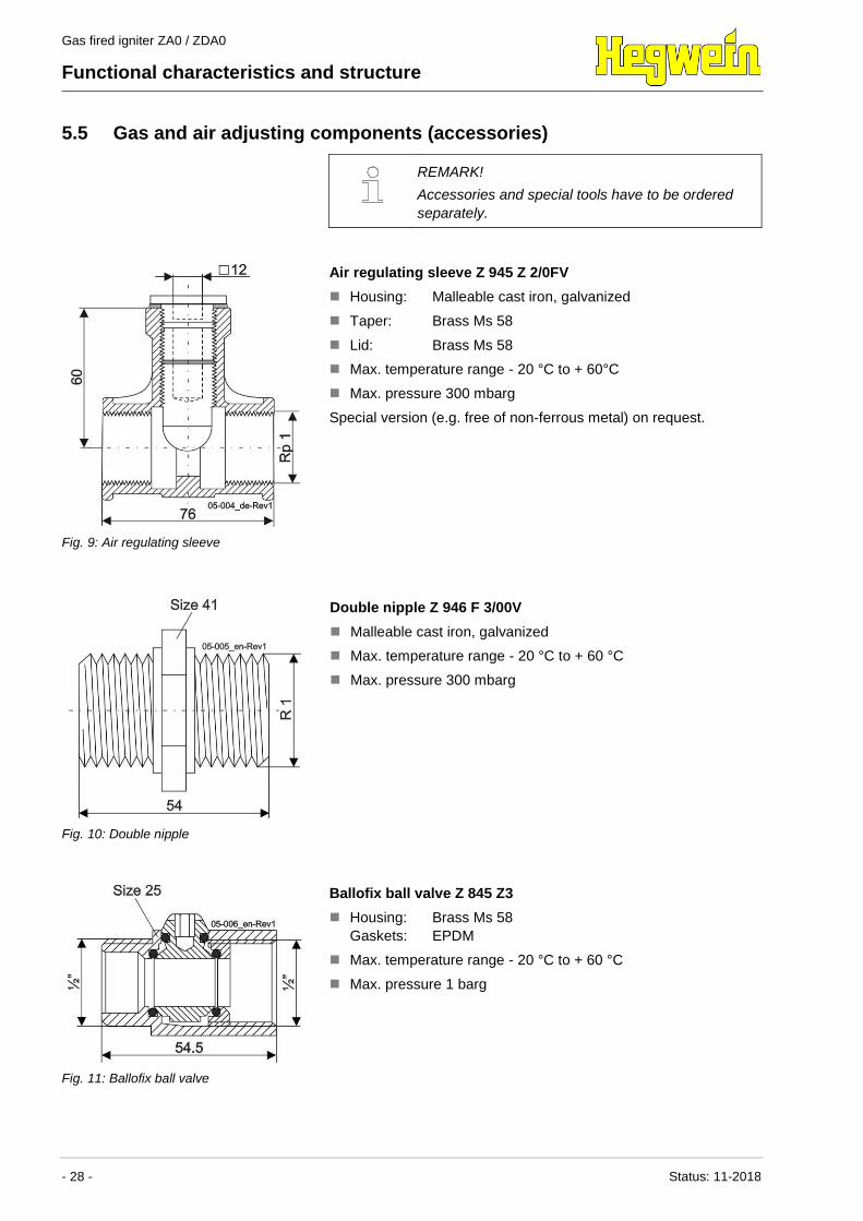
5.5 Gas and air adjusting components (accessories)
REMARK!
Accessories and special tools have to be ordered
separately.
Fig. 9: Air regulating sleeve
Air regulating sleeve Z 945 Z 2/0FV
Housing: Malleable cast iron, galvanized
Taper: Brass Ms 58
Lid: Brass Ms 58
Max. temperature range - 20 °C to + 60°C
Max. pressure 300 mbarg
Special version (e.g. free of non-ferrous metal) on request.
Fig. 10: Double nipple
Double nipple Z 946 F 3/00V
Malleable cast iron, galvanized
Max. temperature range - 20 °C to + 60 °C
Max. pressure 300 mbarg
Fig. 11: Ballofix ball valve
Ballofix ball valve Z 845 Z3
Housing: Brass Ms 58
Gaskets: EPDM
Max. temperature range - 20 °C to + 60 °C
Max. pressure 1 barg

Gas fired igniter ZA0 / ZDA0
Functional characteristics and structure
Status: 11-2018 - 29 -
5.6 Electrical wiring versions
The gas fired igniter can be interconnected with the following units:
Burner control ASD-75 P0…
for continuous operation or intermittent operation, top hat rail
mounting, 230 V AC, 50/60 Hz (special voltage possible),
see relevant HEGWEIN operating manual
Flame relay A 285 K2.3
with 2 SPDT contacts, top hat rail mounting, see relevant
HEGWEIN operating manual
Gas fired igniter ZA0 / ZDA0
Installation and initial commissioning
- 30 - Status: 11-2018
6 Installation and initial commissioning
6.1 Safety
Personnel Installation may only be performed by suitably qualified
specialist staff of the plant installer.
Initial commissioning may only be performed by employees of
the manufacturer or by trained personnel.
Basics
WARNING!
Danger of injury due to faulty installation and
initial commissioning!
Errors during installation and initial commissioning
can result in potentially fatal situations or entail
substantial material damage.
– Prior to any commissioning/maintenance work
that part of the plant where the gas fired igniter
is installed must be switched off and secured
against accidental restart. All feedlines to the
gas fired igniter must be blocked, emptied and
cleaned, if necessary.
– Before starting work, ensure that there is
sufficient freedom of movement for the
installation work.
– Take care when handling open, sharp-edged
components.
– Ensure that the installation site is clean and
tidy. Loose components and tools lying around
or piled on top of each other are a possible
cause of accidents.
– Assemble components professionally and
correctly, observing prescribed screw tightening
torque levels.
– Secure components so that they cannot drop
down or fall over.
Gas fired igniter ZA0 / ZDA0
Installation and initial commissioning
Status: 11-2018 - 31 -
DANGER!
Explosion risk due to leaking fuel or release of
additional units!
Downstream units (e.g. burner/igniter) can be
connected via incorrect operation of the gas fired
igniter.
– The gas fired igniter, and the flame monitor
signal of the gas fired igniter should be
incorporated into an overriding safety controller.
– Only use measurement sockets for short term
measurement purposes on site.
– Do not use measurement sockets for distance
or continuous display.
– Do not bridge measurement sockets, or bring
them into contact with mass under any
circumstances.
– On commissioning, it must be ensured that in
the case of a flame signal breakdown, the flame
signal contact opens within 1 s, and leads to
the safety and fault shutdown via the overriding
safety controller.
Definitions
REMARK!
Air inlet pressure/gas inlet pressure:
Air pressure, respectively gas pressure at the gas
fired igniter’s air or gas port.
Air operating pressure/gas operating pressure:
Permissible air pressure or gas pressure to
operate the gas fired igniter. Pressure to be picked
up at the air or gas pressure test nipple.
Gas fired igniter ZA0 / ZDA0
Installation and initial commissioning
- 32 - Status: 11-2018
6.2 Installation and electrical connection
Ensure that the following tasks are only performed by suitably
trained personnel.
DANGER!
Danger to life due to electrical current!
When touching with current conducting parts, there
is a danger to life.
– Only pull out or unplug the connecting plug or
connector, when the operating current of the
gas fired igniter is switched off.
NOTICE!
- Before connection, check whether the gas fired
igniter is suitable for the mains voltage provided.
- The installer/operator is responsible for the
installation of the gas fired igniter into a system,
which fulfils the stated system specific standards
and guidelines.
- The operator/installer is responsible for
adherence to the permitted environmental
conditions and/or ambient atmosphere, in
accordance with the technical data.
1. Prepare the installation location and installation opening.
From an outer tube length of 3 m observe the following:
– Use a guide tube to prevent sagging of the outer tube.
– The end of the outer tube must project 30 – 80 mm over
the guide tube.
– The annular gap between the outer tube and the guide
tube must be 5 – 15 mm.
Gas fired igniter ZA0 / ZDA0
Installation and initial commissioning
Status: 11-2018 - 33 -
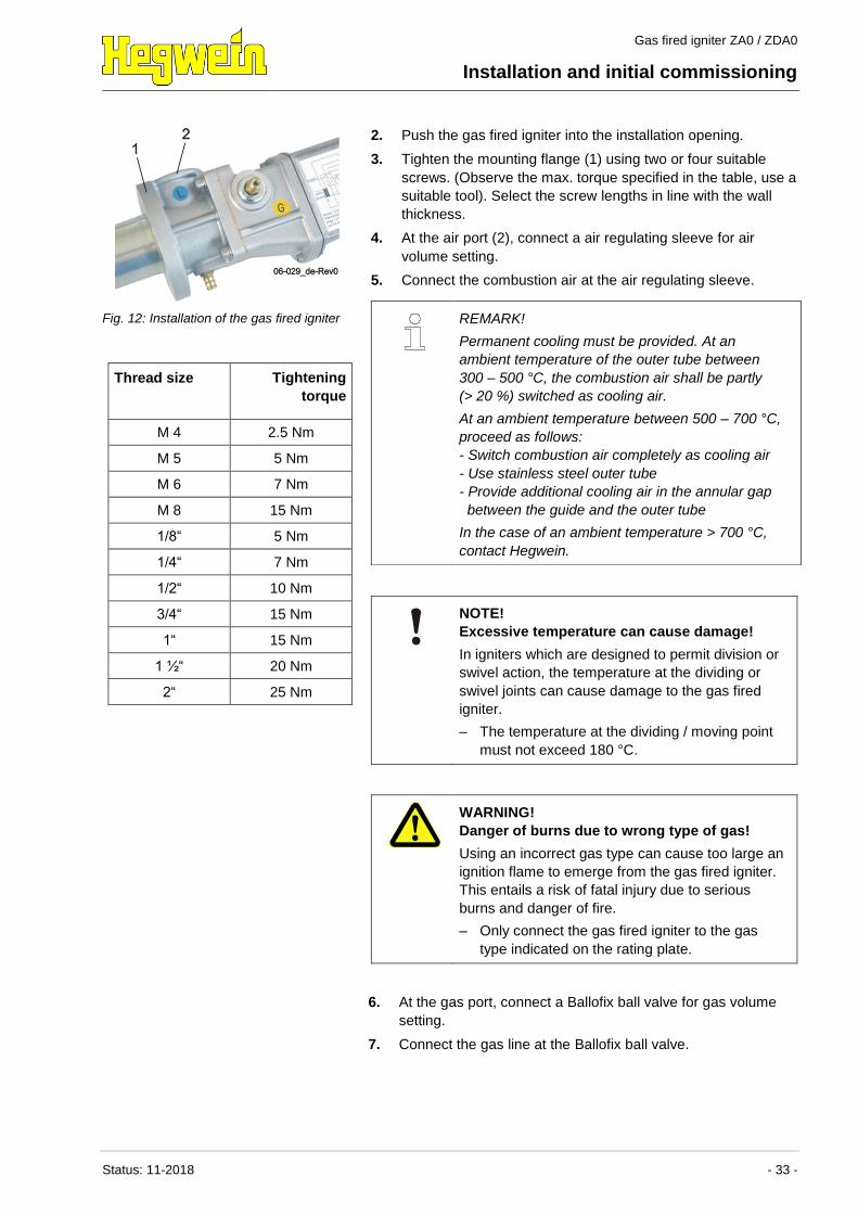
Fig. 12: Installation of the gas fired igniter
Thread size Tightening
torque
M 4 2.5 Nm
M 5 5 Nm
M 6 7 Nm
M 8 15 Nm
1/8“ 5 Nm
1/4“ 7 Nm
1/2“ 10 Nm
3/4“ 15 Nm
1“ 15 Nm
1 ½“ 20 Nm
2“ 25 Nm
2. Push the gas fired igniter into the installation opening.
3. Tighten the mounting flange (1) using two or four suitable
screws. (Observe the max. torque specified in the table, use a
suitable tool). Select the screw lengths in line with the wall
thickness.
4. At the air port (2), connect a air regulating sleeve for air
volume setting.
5. Connect the combustion air at the air regulating sleeve.
NOTE!
Excessive temperature can cause damage!
In igniters which are designed to permit division or
swivel action, the temperature at the dividing or
swivel joints can cause damage to the gas fired
igniter.
– The temperature at the dividing / moving point
must not exceed 180 °C.
REMARK!
Permanent cooling must be provided. At an
ambient temperature of the outer tube between
300 – 500 °C, the combustion air shall be partly
(> 20 %) switched as cooling air.
At an ambient temperature between 500 – 700 °C,
proceed as follows:
- Switch combustion air completely as cooling air
- Use stainless steel outer tube
- Provide additional cooling air in the annular gap
between the guide and the outer tube
In the case of an ambient temperature > 700 °C,
contact Hegwein.
WARNING!
Danger of burns due to wrong type of gas!
Using an incorrect gas type can cause too large an
ignition flame to emerge from the gas fired igniter.
This entails a risk of fatal injury due to serious
burns and danger of fire.
– Only connect the gas fired igniter to the gas
type indicated on the rating plate.
6. At the gas port, connect a Ballofix ball valve for gas volume
setting.
7. Connect the gas line at the Ballofix ball valve.
Gas fired igniter ZA0 / ZDA0
Installation and initial commissioning
- 34 - Status: 11-2018
REMARK!
The gas fired igniter must be connected by the
owner to the plant control system in accordance
with the terminal diagrams.
REMARK!
The high-voltage ignition spark can suppress the
ionization signal to such a degree that the flame
relay is not able to pick up. For this reason, the
plant control system must ensure that the ignition
voltage (“spark transformer” terminal) is switched
off before the end of the ignition safety period (see
EN standard 298). This ensures a short ignition-
free period (approx. 0.5 s).
8. Connect the gas fired igniter in accordance with the relevant
terminal diagram. Remove the plastic blind in the second
cable gland, if a cable is to be introduced there.
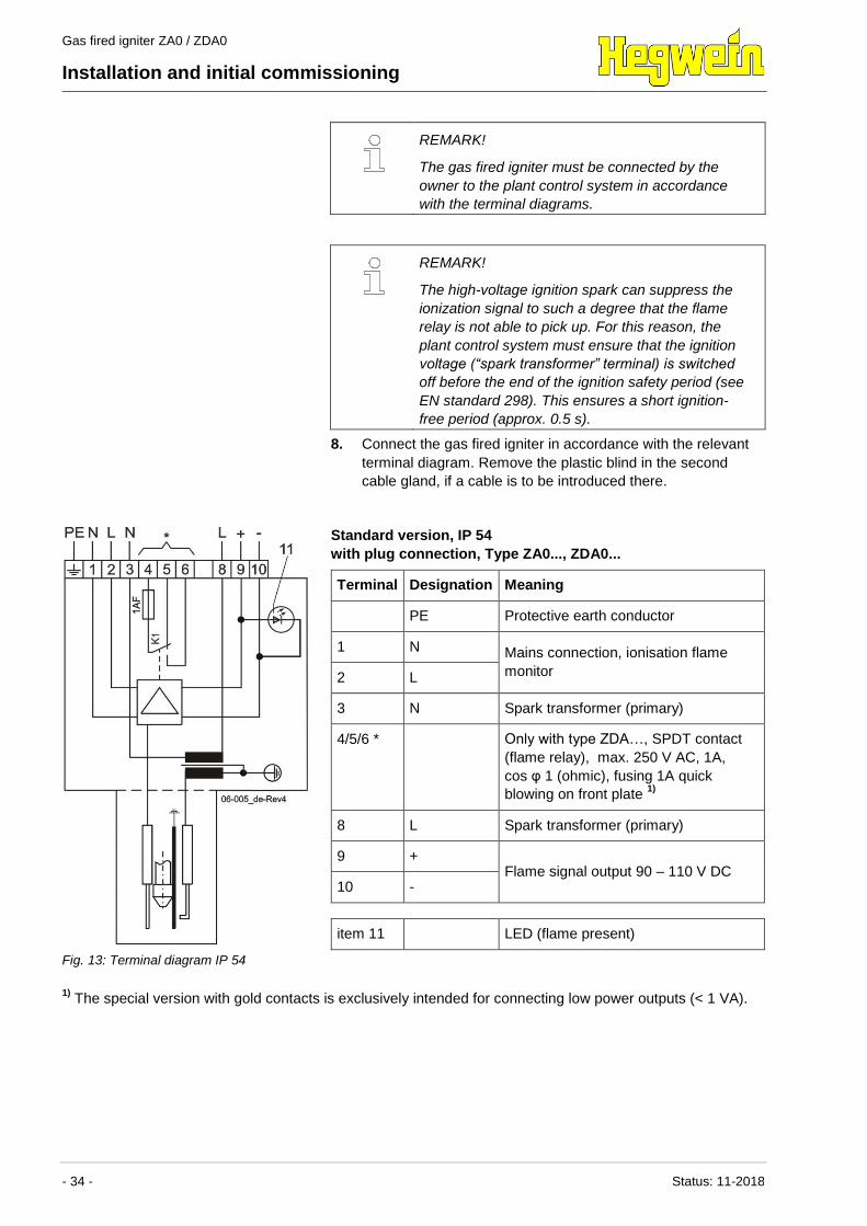
Fig. 13: Terminal diagram IP 54
Standard version, IP 54
with plug connection, Type ZA0..., ZDA0...
Terminal Designation Meaning
PE Protective earth conductor
1 N Mains connection, ionisation flame
monitor 2 L
3 N Spark transformer (primary)
4/5/6 * Only with type ZDA…, SPDT contact
(flame relay), max. 250 V AC, 1A,
cos φ 1 (ohmic), fusing 1A quick
blowing on front plate 1)
8 L Spark transformer (primary)
9 + Flame signal output 90 – 110 V DC
10 -
item 11 LED (flame present)
1) The special version with gold contacts is exclusively intended for connecting low power outputs (< 1 VA).
Gas fired igniter ZA0 / ZDA0
Installation and initial commissioning
Status: 11-2018 - 35 -
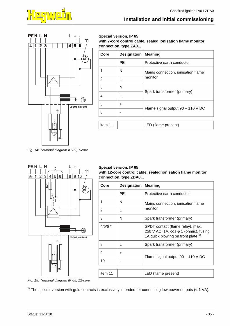
Fig. 14: Terminal diagram IP 65, 7-core
Special version, IP 65
with 7-core control cable, sealed ionisation flame monitor
connection, type ZA0...
Core Designation Meaning
PE Protective earth conductor
1 N Mains connection, ionisation flame
monitor 2 L
3 N Spark transformer (primary)
4 L
5 + Flame signal output 90 – 110 V DC
6 -
item 11 LED (flame present)
Fig. 15: Terminal diagram IP 65, 12-core
Special version, IP 65
with 12-core control cable, sealed ionisation flame monitor
connection, type ZDA0...
Core Designation Meaning
PE Protective earth conductor
1 N Mains connection, ionisation flame
monitor 2 L
3 N Spark transformer (primary)
4/5/6 * SPDT contact (flame relay), max.
250 V AC, 1A, cos φ 1 (ohmic), fusing
1A quick blowing on front plate 1)
8 L Spark transformer (primary)
9 + Flame signal output 90 – 110 V DC
10 -
item 11 LED (flame present)
1) The special version with gold contacts is exclusively intended for connecting low power outputs (< 1 VA).
Gas fired igniter ZA0 / ZDA0
Installation and initial commissioning
- 36 - Status: 11-2018
REMARK!
Close the terminal box/connecting plugs and check
whether all seals, cable strain relief devices etc.
are correctly connected.
6.3 Electrical function test
This test must only be carried out by a specialist trained in the
handling of the plant and its components.
Additionally required protective gear:
Face protection
Safety gloves
Required special tools:
Test diode A10Z2 (accessory part)
DANGER!
Fatal danger due to electrical voltage or high
voltage!
High voltage is present in the ignition electrode for
ignition purposes. Due to the supply voltage of the
ionisation flame monitor, electrical voltage is also
applied to the flame rod. Contact with the
electrodes could be fatal.
– Never come into contact with the ignition
electrode or the flame rod.
DANGER!
Escaping fuel or the release of other devices
may cause an explosion!
A release of the gas fired igniter can cause the
start of subsequent devices (burners).
– Any other devices such as burners and valves
shall therefore be blocked.
DANGER!
Risk of explosion due to leaking gas!
Accidental gas leaks can cause an explosion or
serious burns!
– Before testing, shut off the gas valve!
– Ensure that no residual gas remains, if
necessary inert the gas lines.
Gas fired igniter ZA0 / ZDA0
Installation and initial commissioning
Status: 11-2018 - 37 -
ATTENTION!
Defect due to improper handling!
Improper handling may cause a short circuit or
damages to the product.
– The mounted ionisation flame monitor is a
safety device. In case of damage, return the
ionisation flame monitor to the manufacturer.
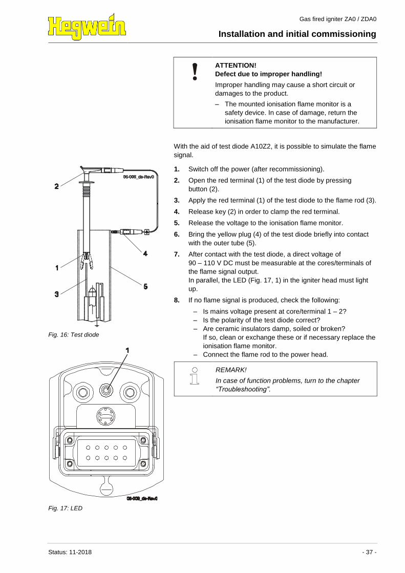
With the aid of test diode A10Z2, it is possible to simulate the flame
signal.
Fig. 16: Test diode
1. Switch off the power (after recommissioning).
2. Open the red terminal (1) of the test diode by pressing
button (2).
3. Apply the red terminal (1) of the test diode to the flame rod (3).
4. Release key (2) in order to clamp the red terminal.
5. Release the voltage to the ionisation flame monitor.
6. Bring the yellow plug (4) of the test diode briefly into contact
with the outer tube (5).
7. After contact with the test diode, a direct voltage of
90 – 110 V DC must be measurable at the cores/terminals of
the flame signal output.
In parallel, the LED (Fig. 17, 1) in the igniter head must light
up.
8. If no flame signal is produced, check the following:
– Is mains voltage present at core/terminal 1 – 2?
– Is the polarity of the test diode correct?
– Are ceramic insulators damp, soiled or broken?
If so, clean or exchange these or if necessary replace the
ionisation flame monitor.
– Connect the flame rod to the power head.
REMARK!
In case of function problems, turn to the chapter
“Troubleshooting”.
Fig. 17: LED
Gas fired igniter ZA0 / ZDA0
Installation and initial commissioning
- 38 - Status: 11-2018
6.4 Setting the required air volume
This may only be performed by trained personnel.
Required special tools:
Customarily available pressure gauge with a measurement
range of 0 – 200 mbar
REMARK!
The required air operating pressure depends -
among other things- on the desired gas operating
pressure.
The calculation formula outlined in step 1 refers to
a normal case, i.e. the gas operating pressure is
100 mbar above the combustion chamber back
pressure.
Any gas operating pressure deviating from this
standard case will require an adaptation of the air
operating pressure.
1. Define the air operating pressure:
A air inlet pressure of 10 mbar plus another 10 mbar for every
m of tube length is required. A gas fired igniter with a tube
length of 5 m should therefore be supplied with
10 mbar + (5 x 10 mbar), i.e. 60 mbar in total (any
backpressures need to be taken into account).
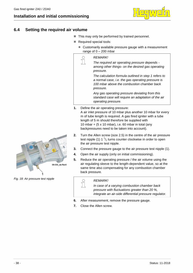
Fig. 18: Air pressure test nipple
2. Turn the Allen screw (size 2.5) in the centre of the air pressure
test nipple (1) 1 1/2 turns counter clockwise in order to open
the air pressure test nipple.
3. Connect the pressure gauge to the air pressure test nipple (1).
4. Open the air supply (only on initial commissioning).
5. Reduce the air operating pressure / the air volume using the
air regulating sleeve to the length-dependent value, so at the
same time also compensating for any combustion chamber
back pressure.
6. After measurement, remove the pressure gauge.
7. Close the Allen screw.
REMARK!
In case of a varying combustion chamber back
pressure with fluctuations greater than 20 %,
integrate an air-side differential pressure regulator.
Gas fired igniter ZA0 / ZDA0
Installation and initial commissioning
Status: 11-2018 - 39 -
6.5 Setting the required gas volume
This may only be performed by trained personnel.
Additionally required safety equipment:
Face protection
Protective gloves
Required special tools:
Customarily available pressure gauge with a measurement
range of 0 – 200 mbar
DANGER!
Risk of explosion due to gas leaks!
An accidental gas leak can cause an explosion or
serious burns!
– Only unscrew the Allen screw of the gas
pressure test nipple for the duration of the test.
– Never allow any naked flame or ignition source
to enter the danger area.
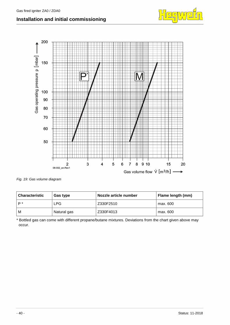
1. Define the required gas volume on the basis of the relevant
characteristic curve in the gas volume diagram.
As a rule, the gas operating pressure is 100 mbar above
combustion chamber back pressure.
REMARK!
If a higher gas inlet pressure was specified in the
order, then pressure reducing orifices have already
been screwed into the two gas inlet threads in the
factory. The igniter is consequently adapted for gas
inlet pressures above 150 mbar.
Precision setting is performed using the Ballofix
ball valve.
In case of gas inlet pressures above 500 mbar, this
setting is extremely difficult. In these cases, the
pressure reducing orifices must be retrofitted.
When ordering pressure reducing orifices, specify
the gas inlet pressure.
REMARK!
The illustrated diagram is based on average values
in respect of gas density, gas composition, calorific
value, igniter version, igniter tube length and
optimum ambient conditions, such as free burn-out
and pressureless combustion chamber. The gas
operating pressure values determined from the
diagram must consequently be viewed as guideline
values. Depending on the plant conditions, the
actually required values may deviate from this.
Gas fired igniter ZA0 / ZDA0
Installation and initial commissioning
- 40 - Status: 11-2018
Fig. 19: Gas volume diagram
Characteristic Gas type Nozzle article number Flame length (mm)
P * LPG Z330F2510 max. 600
M Natural gas Z330F4013 max. 600
* Bottled gas can come with different propane/butane mixtures. Deviations from the chart given above may
occur.
Gas fired igniter ZA0 / ZDA0
Installation and initial commissioning
Status: 11-2018 - 41 -
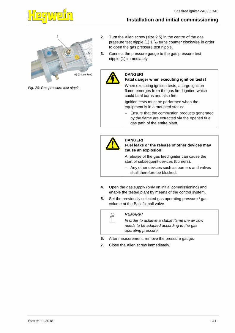
Fig. 20: Gas pressure test nipple
2. Turn the Allen screw (size 2.5) in the centre of the gas
pressure test nipple (1) 1 1/2 turns counter clockwise in order
to open the gas pressure test nipple.
3. Connect the pressure gauge to the gas pressure test
nipple (1) immediately.
DANGER!
Fatal danger when executing ignition tests!
When executing ignition tests, a large ignition
flame emerges from the gas fired igniter, which
could fatal burns and also fire.
Ignition tests must be performed when the
equipment is in a mounted status:
– Ensure that the combustion products generated
by the flame are extracted via the opened flue
gas path of the entire plant.
DANGER!
Fuel leaks or the release of other devices may
cause an explosion!
A release of the gas fired igniter can cause the
start of subsequent devices (burners).
– Any other devices such as burners and valves
shall therefore be blocked.
4. Open the gas supply (only on initial commissioning) and
enable the tested plant by means of the control system.
5. Set the previously selected gas operating pressure / gas
volume at the Ballofix ball valve.
6. After measurement, remove the pressure gauge.
7. Close the Allen screw immediately.
REMARK!
In order to achieve a stable flame the air flow
needs to be adapted according to the gas
operating pressure.
Gas fired igniter ZA0 / ZDA0
Installation and initial commissioning
- 42 - Status: 11-2018
6.6 Checking the setting result
If correctly set, the following setting results should be in place
following initial commissioning:
Immediate ignition
Optically good flame pattern / flame signal 90 – 110 V DC, or
optimized ionisation flow > 10 A (test sockets in the front
panel of the igniter head in the standard version)
Flame length max. 600 mm at max. output of 120 kW and free
burn-out
Gas fired igniter ZA0 / ZDA0
Operation
Status: 11-2018 - 43 -
7 Operation
7.1 Safety
Personal To be executed by suitably trained personnel only.
Basics
WARNING!
Danger of injury due to incorrect operation!
Incorrect operation can result in serious personal
injury or material damage.
– Before starting work, ensure that all covers and
safety devices are installed and in correct
working order.
– Never disable safety devices during operation.
– Only operate the gas fired igniter in installed
condition.
– Ensure order and cleanliness in the work area.
Loose components and tools lying around or
piled on top of each other are a possible cause
of accidents.
7.2 Operation
REMARK!
Operation of the gas fired igniters takes place at
the plant control system in which the device is
integrated. Manual operation at the gas fired igniter
itself is not required.
Gas fired igniter ZA0 / ZDA0
Maintenance
- 44 - Status: 11-2018
8 Maintenance
8.1 Safety
Personnel To be executed by suitably trained personnel only.
Basics
WARNING!
Danger of injury due to incorrectly executed
maintenance work!
Incorrectly done maintenance work can result in
serious personal injury or material damage.
– Before starting work, ensure that there is
sufficient freedom of movement for the
installation work.
– Ensure that the installation site is clean and
tidy. Loose components and tools lying around
or piled on top of each other are a possible
cause of accidents.
– When components are removed, ensure correct
reassembly. Remount all fastening components
and adhere to specified screw tightening torque
levels.
8.2 Maintenance, general
The gas fired igniter should be function tested at regular intervals
(e.g. every 3 months).
If the gas fired igniter is operated with air containing dust, checks
must be performed at shorter intervals, as electrically conductive
dirt deposits or moisture on the ceramic insulators of the igniter can
result in malfunctions.
The inner resistance of the ionization path is M. These high
resistance levels call for the ceramic insulators to be in perfect
working order.
Only a few parts are subject to wear in normal operation (see
chapter “Spare parts list”. These parts must be exchanged if
defects and malfunctions occur with increased frequency.
Gas fired igniter ZA0 / ZDA0
Maintenance
Status: 11-2018 - 45 -
8.3 Conditions for maintenance work
Take care of the following warnings before carrying out any
maintenance work (sections 8.3.1 to 8.3.5):
DANGER!
Fatal danger due to electrical voltage or high
voltage!
High voltage is present in the ignition electrode for
ignition purposes. Due to the supply voltage of the
ionisation flame monitor, electrical voltage is also
applied to the flame rod. Contact with the
electrodes could be fatal.
– Never come into contact with the ignition
electrode or the flame rod.
Performing work at the spark transformer entails a
risk of fatal injury due to electric shocks!
– Before starting work, switch off the power
supply and make sure it cannot be inadvertently
switched back on. Observe the 5 safety rules.
– Before touching parts carrying voltage, ensure
that no residual voltage remains.
DANGER!
Risk of explosion due to leaking gas!
Accidental gas leaks can cause an explosion or
serious burns!
When carrying out maintenance work, shut off the
gas valve!
– Ensure that no residual gas remains, if
necessary inert the gas lines.
– Completely separate the gas fired igniter from
the power supply and disconnect the gas / air
supply.
The maintenance work listed below can now be performed.
Gas fired igniter ZA0 / ZDA0
Maintenance
- 46 - Status: 11-2018
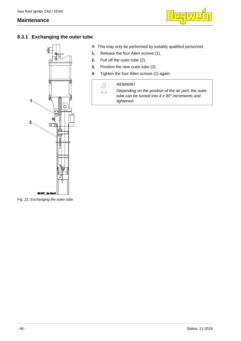
8.3.1 Exchanging the outer tube
Fig. 21: Exchanging the outer tube
This may only be performed by suitably qualified personnel.
1. Release the four Allen screws (1).
2. Pull off the outer tube (2).
3. Position the new outer tube (2).
4. Tighten the four Allen screws (1) again.
REMARK!
Depending on the position of the air port, the outer
tube can be turned into 4 x 90° increments and
tightened.
Gas fired igniter ZA0 / ZDA0
Maintenance
Status: 11-2018 - 47 -
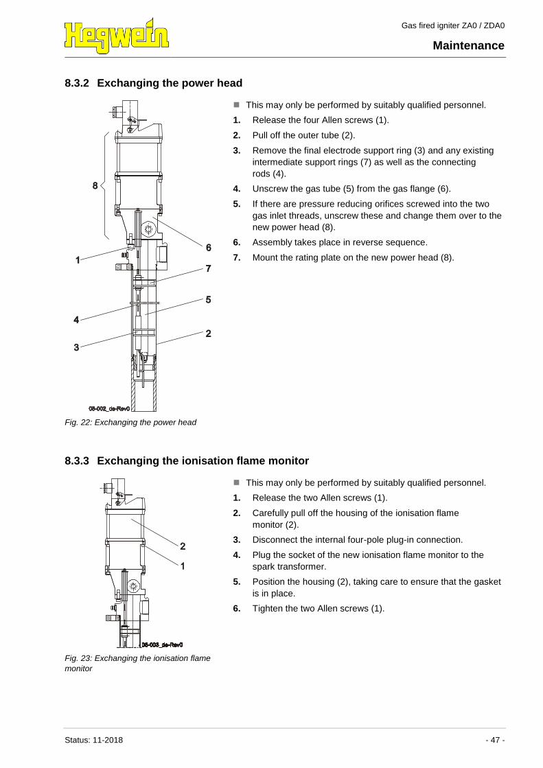
8.3.2 Exchanging the power head
Fig. 22: Exchanging the power head
This may only be performed by suitably qualified personnel.
1. Release the four Allen screws (1).
2. Pull off the outer tube (2).
3. Remove the final electrode support ring (3) and any existing
intermediate support rings (7) as well as the connecting
rods (4).
4. Unscrew the gas tube (5) from the gas flange (6).
5. If there are pressure reducing orifices screwed into the two
gas inlet threads, unscrew these and change them over to the
new power head (8).
6. Assembly takes place in reverse sequence.
7. Mount the rating plate on the new power head (8).
8.3.3 Exchanging the ionisation flame monitor
Fig. 23: Exchanging the ionisation flame
monitor
This may only be performed by suitably qualified personnel.
1. Release the two Allen screws (1).
2. Carefully pull off the housing of the ionisation flame
monitor (2).
3. Disconnect the internal four-pole plug-in connection.
4. Plug the socket of the new ionisation flame monitor to the
spark transformer.
5. Position the housing (2), taking care to ensure that the gasket
is in place.
6. Tighten the two Allen screws (1).
Gas fired igniter ZA0 / ZDA0
Maintenance
- 48 - Status: 11-2018
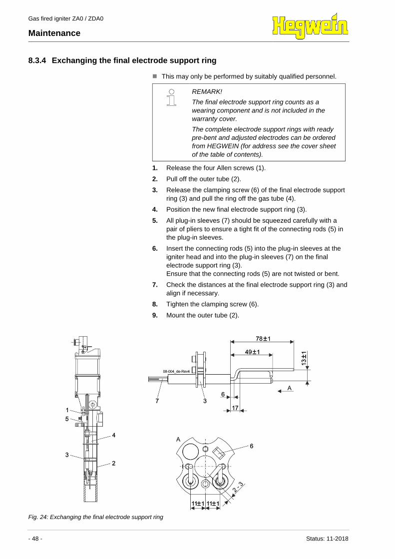
8.3.4 Exchanging the final electrode support ring
This may only be performed by suitably qualified personnel.
REMARK!
The final electrode support ring counts as a
wearing component and is not included in the
warranty cover.
The complete electrode support rings with ready
pre-bent and adjusted electrodes can be ordered
from HEGWEIN (for address see the cover sheet
of the table of contents).
1. Release the four Allen screws (1).
2. Pull off the outer tube (2).
3. Release the clamping screw (6) of the final electrode support
ring (3) and pull the ring off the gas tube (4).
4. Position the new final electrode support ring (3).
5. All plug-in sleeves (7) should be squeezed carefully with a
pair of pliers to ensure a tight fit of the connecting rods (5) in
the plug-in sleeves.
6. Insert the connecting rods (5) into the plug-in sleeves at the
igniter head and into the plug-in sleeves (7) on the final
electrode support ring (3).
Ensure that the connecting rods (5) are not twisted or bent.
7. Check the distances at the final electrode support ring (3) and
align if necessary.
8. Tighten the clamping screw (6).
9. Mount the outer tube (2).
Fig. 24: Exchanging the final electrode support ring
Gas fired igniter ZA0 / ZDA0
Maintenance
Status: 11-2018 - 49 -
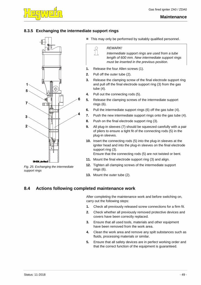
8.3.5 Exchanging the intermediate support rings
Fig. 25: Exchanging the intermediate
support rings
This may only be performed by suitably qualified personnel.
1. Release the four Allen screws (1).
2. Pull off the outer tube (2).
3. Release the clamping screw of the final electrode support ring
and pull off the final electrode support ring (3) from the gas
tube (4).
4. Pull out the connecting rods (5).
5. Release the clamping screws of the intermediate support
rings (6).
6. Pull the intermediate support rings (6) off the gas tube (4).
7. Push the new intermediate support rings onto the gas tube (4).
8. Push on the final electrode support ring (3).
9. All plug-in sleeves (7) should be squeezed carefully with a pair
of pliers to ensure a tight fit of the connecting rods (5) in the
plug-in sleeves.
10. Insert the connecting rods (5) into the plug-in sleeves at the
igniter head and into the plug-in sleeves on the final electrode
support ring (3).
Ensure that the connecting rods (5) are not twisted or bent.
11. Mount the final electrode support ring (3) and align.
12. Tighten all clamping screws of the intermediate support
rings (6).
13. Mount the outer tube (2).
REMARK!
Intermediate support rings are used from a tube
length of 600 mm. New intermediate support rings
must be inserted in the previous position.
8.4 Actions following completed maintenance work
After completing the maintenance work and before switching on,
carry out the following steps:
1. Check all previously released screw connections for a firm fit.
2. Check whether all previously removed protective devices and
covers have been correctly replaced.
3. Ensure that all used tools, materials and other equipment
have been removed from the work area.
4. Clean the work area and remove any spilt substances such as
fluids, processing materials or similar.
5. Ensure that all safety devices are in perfect working order and
that the correct function of the equipment is guaranteed.
Gas fired igniter ZA0 / ZDA0
Troubleshooting
- 50 - Status: 11-2018
9 Troubleshooting
The following chapter provides information on possible causes for
faults and describes the work required to remedy them.
If faults occur on a more frequent basis, reduce the maintenance
intervals in line with the actual degree of stress on the system.
In case of faults which cannot be remedied following these
instructions, contact HEGWEIN. For the servicing address, see the
cover sheet of the table of contents.
9.1 Safety
Personnel This may only be performed by trained personnel.
Basics
WARNING!
Danger of injury due to incorrectly performed
maintenance work!
Incorrectly executed maintenance work can result
in serious personal injury or material damage.
– Before starting work, ensure that there is
sufficient freedom of movement for the
installation work.
– Ensure that the installation site is clean and
tidy. Loose components and tools lying around
or piled on top of each other are a possible
cause of accidents.
– When components are removed, ensure correct
reassembly. Remount all fastening components
and adhere to specified screw tightening torque
levels.
Response in case of faults Basic rules of procedure:
1. Determine the cause of the fault.
2. Before starting work, switch off the power supply and make
sure it cannot be inadvertently switched back on. Observe the
5 safety rules.
3. Completely disconnect the gas fired igniter from the energy
supply and disconnect the gas/air supply.
4. Inform the person in charge at the site immediately about the
fault.
5. Depending on the type of fault, have it remedied by authorized
specialist personnel.
REMARK!
The troubleshooting table listed below provides
information on how to remedy faults.
Gas fired igniter ZA0 / ZDA0
Troubleshooting
Status: 11-2018 - 51 -
9.2 Troubleshooting table
Fault Possible cause Solution To be done by
Spark does not form
(Not: Carry out
optical check of
ignition spark with
gas valve closed in
darkened room)
Gas fired igniter is not receiving
any voltage
Check wiring
Check control system
Qualified
electrician
Ignition electrode is burned out Clean the inside of the gas fired
igniter and replace ignition
electrode, bend to original
position
Qualified
personnel
Electrode distance is too large
or electrode has short circuited
Clean inside of gas fired igniter
if necessary and bend ignition
electrode to distance of
2 - 3 mm
Qualified
personnel
Spark transformer defective Exchange spark transformer Manufacturer/
Qualified
electrician
Layer of scale on spark
electrode or earth rod/ bolt
Clean inside of gas fired igniter
and remove deposits using
emery paper
Qualified
personnel
Ceramic insulator broken Exchange ceramic insulator,
intermediate support ring or
final electrode support
Qualified
personnel
Flame fails to form No combustion air available due
to defective air flap or valve
Exchange air flap or valve Qualified
personnel
No combustion air available due
to closed throttle organs
Open throttle organs Operator
No combustion air available due
to blocked supply line
Unblock line Qualified
personnel
No gas available because
supply line is too long
Dimension supply line
accordingly, if necessary
change the position of the gas
fired igniter
Qualified
personnel
No gas available, as gas supply
line still inert with N2
Carry out several ignition
attempts until line has filled with
gas
Operator
No gas available, as gas valve
defective
Exchange gas valve Gas specialist /
owner
Gas to air ratio is incorrect Check settings of the gas and
air operating pressure. Check
values and correct on the basis
of the diagrams
Qualified
personnel
Wrong gas Only use gas specified on the
rating plate
Qualified
personnel
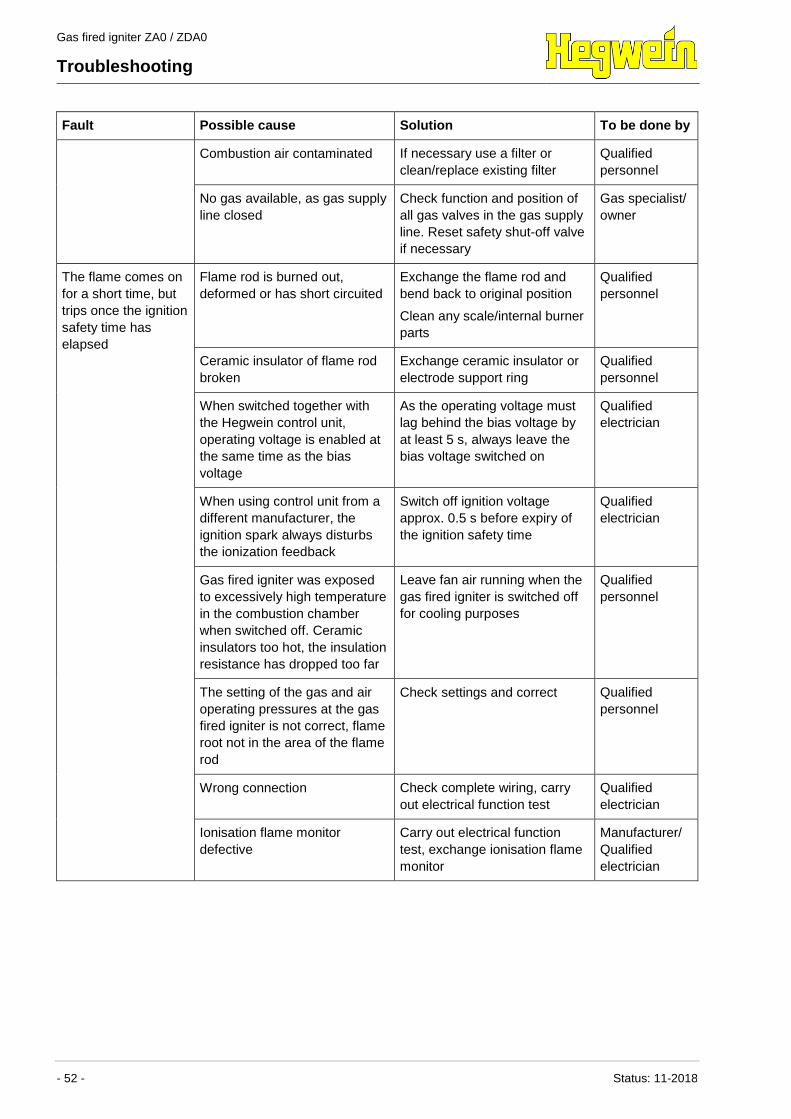
Gas fired igniter ZA0 / ZDA0
Troubleshooting
- 52 - Status: 11-2018
Fault Possible cause Solution To be done by
Combustion air contaminated If necessary use a filter or
clean/replace existing filter
Qualified
personnel
No gas available, as gas supply
line closed
Check function and position of
all gas valves in the gas supply
line. Reset safety shut-off valve
if necessary
Gas specialist/
owner
The flame comes on
for a short time, but
trips once the ignition
safety time has
elapsed
Flame rod is burned out,
deformed or has short circuited
Exchange the flame rod and
bend back to original position
Clean any scale/internal burner
parts
Qualified
personnel
Ceramic insulator of flame rod
broken
Exchange ceramic insulator or
electrode support ring
Qualified
personnel
When switched together with
the Hegwein control unit,
operating voltage is enabled at
the same time as the bias
voltage
As the operating voltage must
lag behind the bias voltage by
at least 5 s, always leave the
bias voltage switched on
Qualified
electrician
When using control unit from a
different manufacturer, the
ignition spark always disturbs
the ionization feedback
Switch off ignition voltage
approx. 0.5 s before expiry of
the ignition safety time
Qualified
electrician
Gas fired igniter was exposed
to excessively high temperature
in the combustion chamber
when switched off. Ceramic
insulators too hot, the insulation
resistance has dropped too far
Leave fan air running when the
gas fired igniter is switched off
for cooling purposes
Qualified
personnel
The setting of the gas and air
operating pressures at the gas
fired igniter is not correct, flame
root not in the area of the flame
rod
Check settings and correct Qualified
personnel
Wrong connection Check complete wiring, carry
out electrical function test
Qualified
electrician
Ionisation flame monitor
defective
Carry out electrical function
test, exchange ionisation flame
monitor
Manufacturer/
Qualified
electrician
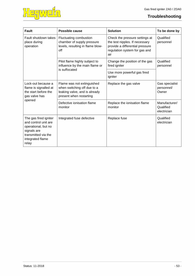
Gas fired igniter ZA0 / ZDA0
Troubleshooting
Status: 11-2018 - 53 -
Fault Possible cause Solution To be done by
Fault shutdown takes
place during
operation
Fluctuating combustion
chamber of supply pressure
levels, resulting in flame blow-
off
Check the pressure settings at
the test nipples. If necessary
provide a differential pressure
regulation system for gas and
air
Qualified
personnel
Pilot flame highly subject to
influence by the main flame or
is suffocated
Change the position of the gas
fired igniter
Qualified
personnel
Use more powerful gas fired
igniter
Lock-out because a
flame is signalled at
the start before the
gas valve has
opened
Flame was not extinguished
when switching off due to a
leaking valve, and is already
present when restarting
Replace the gas valve Gas specialist
personnel/
Owner
Defective ionisation flame
monitor
Replace the ionisation flame
monitor
Manufacturer/
Qualified
electrician
The gas fired igniter
and control unit are
operational, but no
signals are
transmitted via the
integrated flame
relay
Integrated fuse defective Replace fuse Qualified
electrician
Gas fired igniter ZA0 / ZDA0
Dismantling / Disposal
- 54 - Status: 11-2018
10 Dismantling / Disposal
Once it has reached the end of its service life, the gas fired igniter
has to be dismantled and sent for ecologically responsible
disposal.
10.1 Safety
Personnel This may only be performed by trained personnel.
Basics
WARNING!
Danger of injury due to incorrect dismantling!
Residual stored energy, sharp components,
pointed corners and edges on or in the gas fired
igniter or on the required tools can cause injury.
– Before starting work, ensure that there is
sufficient space available.
– Take particular care when dealing with sharp-
edged components.
– Ensure that the installation site is clean and
tidy. Loose components and tools lying around
or piled on top of each other are a possible
cause of accidents.
– If any points are unclear, consult the
manufacturer.
10.2 Dismantling
Before starting to dismantle it, carry out the following steps:
DANGER!
Potentially fatal injury due to electrical current!
Contact with live components can cause fatal
injury.
– Before starting dismantling work, switch off the
electrical supply and finally disconnect.
Gas fired igniter ZA0 / ZDA0
Dismantling / Disposal
Status: 11-2018 - 55 -
DANGER!
Risk of explosion due to leaking gas!
Accidental gas leaks can cause an explosion or
serious burns!
When dismantling, shut off the gas valve!
– Ensure that no residual gas remains, if
necessary inert the gas lines.
– If gas is unintentionally released into the
atmosphere, immediately shut off the gas flow.
Prevent gas entering drainage systems,
basements, work pits or other locations in which
collected gas could cause a hazard.
1. Switch off the gas fired igniter and secure it against being
switched back on.
2. Completely disconnect the gas fired igniter from the energy
supply and gas / air supply.
3. Remove operating and auxiliary materials as well as residual
processing materials and ensure their ecologically responsible
disposal.
The gas fired igniter can now be cleaned for separation and
dismantled in compliance with applicable occupational safety and
environmental protection legislation.
10.3 Disposal
Provided no return acceptance or disposal agreement has been
concluded, the components once dismantled can be sent for
recycling:
Send metals for recycling.
Send plastic elements for recycling.
Dispose of the remaining components separated according to
material properties.
NOTE!
Environmental damage due to incorrect
disposal!
Electric scrap, electronic components, lubricants
and other auxiliary materials are subject to special
waste treatment and may only be disposed of by
authorized specialist companies!
The local authorities or specialist disposal companies can provide
information on environmentally responsible disposal.
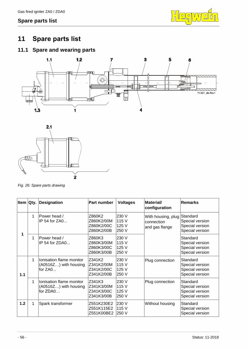
Gas fired igniter ZA0 / ZDA0
Spare parts list
- 56 - Status: 11-2018
11 Spare parts list
11.1 Spare and wearing parts
Fig. 26: Spare parts drawing
Item Qty. Designation Part number Voltages Material/
configuration
Remarks
1
1 Power head / IP 54 for ZA0...
Z860K2 Z860K2/00M Z860K2/00C Z860K2/00B
230 V 115 V 125 V 250 V
With housing, plug
connection
and gas flange
Standard Special version Special version Special version
1 Power head / IP 54 for ZDA0...
Z860K3 Z860K3/00M Z860K3/00C Z860K3/00B
230 V 115 V 125 V 250 V
Standard Special version Special version Special version
1.1
1 Ionisation flame monitor (A0516Z…) with housing for ZA0...
Z341K2 Z341K2/00M Z341K2/00C Z341K2/00B
230 V 115 V 125 V 250 V
Plug connection Standard Special version Special version Special version
1 Ionisation flame monitor (A0516Z…) with housing for ZDA0…
Z341K3 Z341K3/00M Z341K3/00C Z341K3/00B
230 V 115 V 125 V 250 V
Plug connection Standard Special version Special version Special version
1.2 1 Spark transformer Z551K230E2 Z551K115E2 Z551K00BE2
230 V 115 V 250 V
Without housing Standard Special version Special version
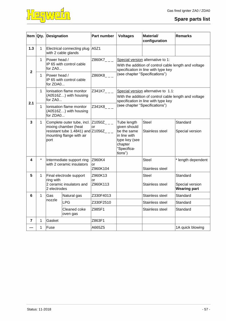
Gas fired igniter ZA0 / ZDA0
Spare parts list
Status: 11-2018 - 57 -
Item Qty. Designation Part number Voltages Material/
configuration
Remarks
1.3 1 Electrical connecting plug with 2 cable glands
A5Z1
2
1 Power head / IP 65 with control cable for ZA0...
Z860K7_ _ _ Special version alternative to 1:
With the addition of control cable length and voltage specification in line with type key (see chapter “Specifications”) 1 Power head /
IP 65 with control cable for ZDA0...
Z860K8_ _ _
2.1
1 Ionisation flame monitor (A0516Z…) with housing for ZA0...
Z341K7_ _ _ Special version alternative to 1.1:
With the addition of control cable length and voltage specification in line with type key (see chapter “Specifications”) 1 Ionisation flame monitor
(A0516Z…) with housing for ZDA0...
Z341K8_ _ _
3 1 Complete outer tube, incl. mixing chamber (heat resistant tube 1.4841) and mounting flange with air port
Z1050Z_ _ _ or Z1056Z_ _ _
Tube length given should be the same in line with type key (see chapter “Specifica-tions”)
Steel Stainless steel
Standard Special version
4 * Intermediate support ring with 2 ceramic insulators
Z960K4 or Z960K104
Steel Stainless steel
* length dependent
5 1 Final electrode support ring with 2 ceramic insulators and 2 electrodes
Z960K13 or Z960K113
Steel Stainless steel
Standard Special version Wearing part
6 1 Gas nozzle
Natural gas Z330F4013 Stainless steel Standard
LPG Z330F2510 Stainless steel Standard
Cleaned coke oven gas
Z985F1 Stainless steel Standard
7 1 Gasket Z863F1
--- 1 Fuse A665Z5 1A quick blowing
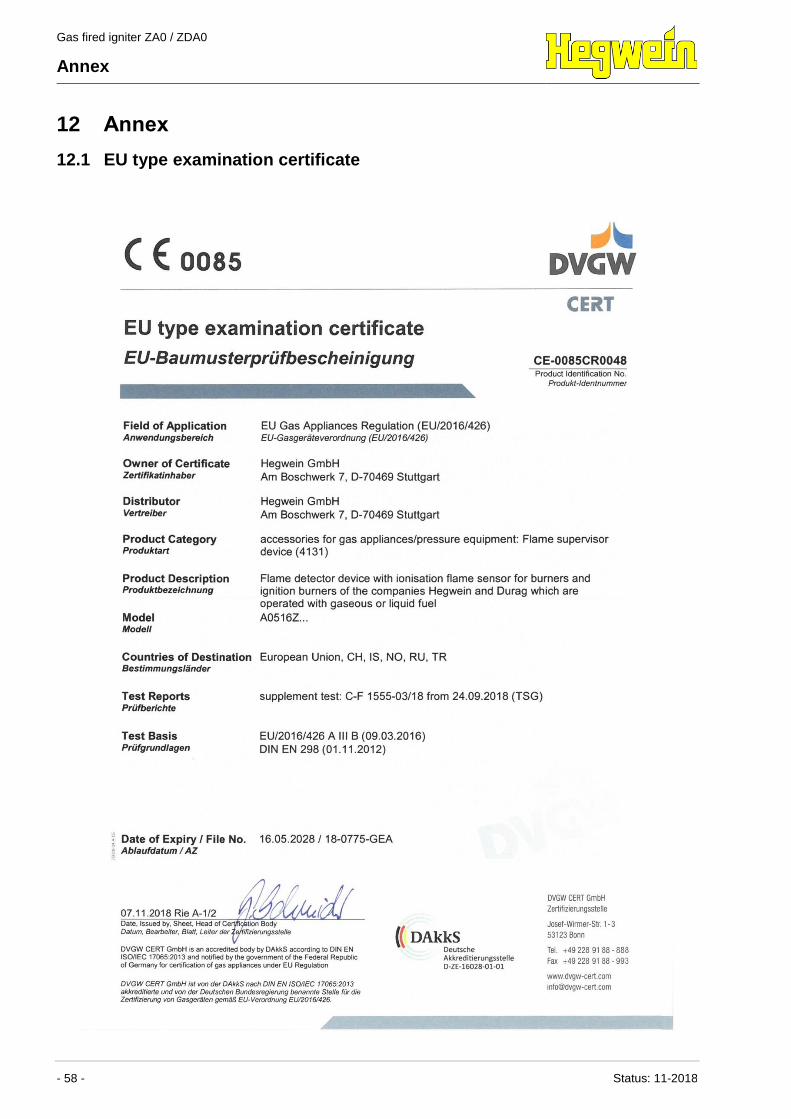
Gas fired igniter ZA0 / ZDA0
Annex
- 58 - Status: 11-2018
12 Annex
12.1 EU type examination certificate
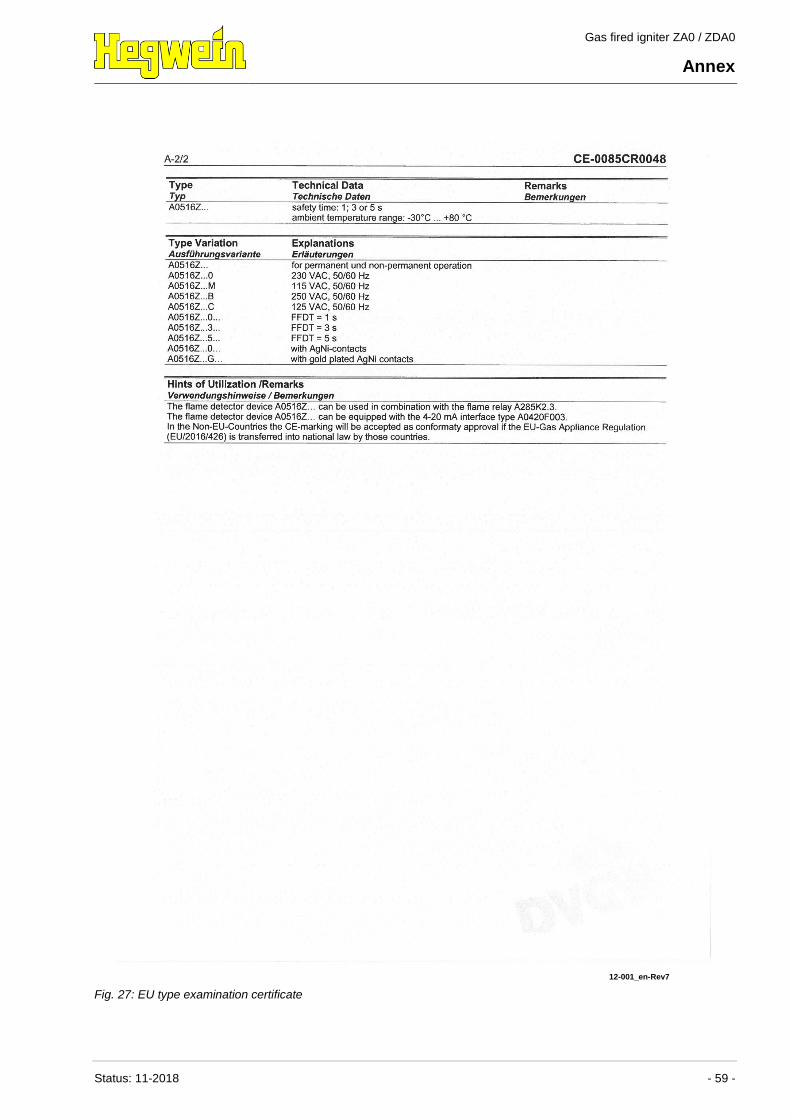
Gas fired igniter ZA0 / ZDA0
Annex
Status: 11-2018 - 59 -
12-001_en-Rev7
Fig. 27: EU type examination certificate
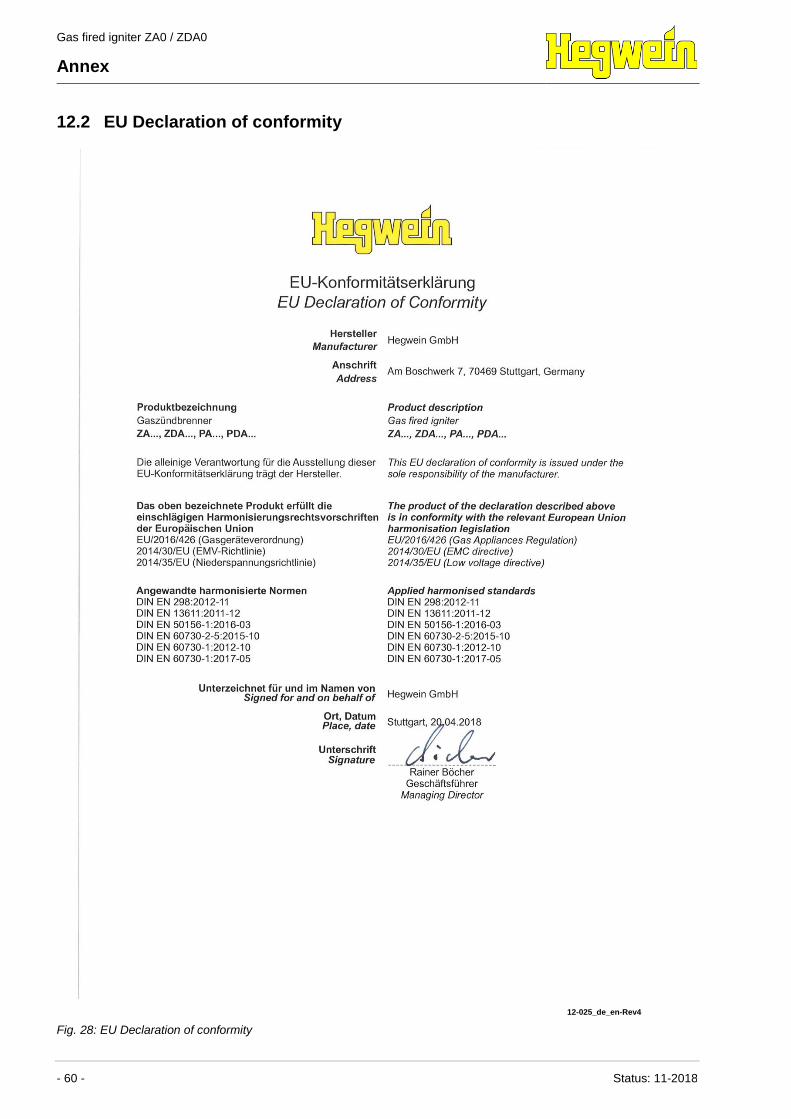
Gas fired igniter ZA0 / ZDA0
Annex
- 60 - Status: 11-2018
12.2 EU Declaration of conformity
12-025_de_en-Rev4
Fig. 28: EU Declaration of conformity
Recommended