http://fun3d.larc.nasa.gov
FUN3D v12.4 Training
Session 8: Parameterization Tools
Bill Jones
FUN3D Training Workshop March 24-‐25, 2014

http://fun3d.larc.nasa.gov
Setting
2 FUN3D Training Workshop March 24-‐25, 2014
• FUN3D shape design relies on a pre-defined relationship between a set of parameters, or design variables, and the discrete surface mesh coordinates
• Given DV, surface parameterization determines Xsurf - For example, given the current value of
wing thickness at a location, what are the corresponding xyz-coordinates of the mesh?
• This narrows down the number of design variables from hundreds of thousands (raw mesh points) to dozens or hundreds - Optimizers will perform more efficiently - Smoother design space
• An additional requirement of the parameterization package is that it provides the Jacobian of the relationship between the design variables and the surface mesh,
• While users may provide their own parameterization scheme, FUN3D is set up to handle three common packages: - MASSOUD: Aircraft-centric design variables (thickness, camber,
planform, twist, etc) - BandAids: General FFD based tool - Sculptor®: Commercial package from Optimal Solutions
€
∂Xsurf ∂DV

http://fun3d.larc.nasa.gov
Learning Goals
3
• Parameterize geometry with respect to DVs to control shape - MASSOUD - BandAids
• Generate perturbed surface mesh and SDs for FUN3D design - Visual validation
• What we will not cover - Body transformations - How to use the data in FUN3D
• That will be covered in the next session
FUN3D Training Workshop March 24-‐25, 2014

http://fun3d.larc.nasa.gov
MASSOUD
4
• Multidisciplinary Aerodynamic-Structural Shape Optimization Using Deformation - AIAA-2000-4911 (Jamshid Samareh)
• Used to generate consistent models for MDAO - Same shape changes communicated across all disciplines
• Highly tailored for aerodynamic shapes - Parameters familiar to engineer
• Mesh based parameterization
FUN3D Training Workshop March 24-‐25, 2014

http://fun3d.larc.nasa.gov
MASSOUD Key Ideas
5
1. Uses soft object animation algorithms for deforming meshes - Nonlinear global deformation (twist and dihedral) - NURBS surface (camber and thickness) - Free-form deformation (planform)
2. Parameterizes the discipline meshes - Avoids mesh regeneration
3. Parameterizes the changes in shape, not the shape itself - No need to reproduce shape
• Reduces the number of design variables
FUN3D Training Workshop March 24-‐25, 2014

http://fun3d.larc.nasa.gov
MASSOUD Twist and Shear
6
• Nonlinear Global Deformation - Wrapped in twist cylinder
• Twisted and sheared in planes along span normal to twist vector
FUN3D Training Workshop March 24-‐25, 2014
Twist parameterization of a generic wing
Twist parameterization of a generic transport
Extreme deformation of a generic transport

http://fun3d.larc.nasa.gov
MASSOUD Camber and Thickness
7
• Non-Uniform Rational B-Spline (NURBS) - Represents the shape changes not the shape
FUN3D Training Workshop March 24-‐25, 2014
NURBS Control Points for Camber and Thickness
Camber
Extreme Camber and Thickness deformation
Thickness

http://fun3d.larc.nasa.gov
MASSOUD Planform
8
• Free-form Deformation (FFD) - Surround shapes with quadrilaterals
FUN3D Training Workshop March 24-‐25, 2014
Baseline
Control Points for FFD
Deformed
FFD control polygon

http://fun3d.larc.nasa.gov
MASSOUD Installation
9
• Distributed as source code
- Single Makefile uses GNU C compiler (gcc) • Any localization must be done manually
- Creates two executables • `massoudDesignDriver` creates parameterization • `massoud` surface mesh perturbation with sensitivity data
FUN3D Training Workshop March 24-‐25, 2014

http://fun3d.larc.nasa.gov
MASSOUD Process
10 FUN3D Training Workshop March 24-‐25, 2014
Step 1: Determine # and
locations of design variables
Step 2: Create baseline
analysis mesh for discipline N
Step 3: Parameterize each
discipline massoudDesignDriver!
Step 4: Perturb and
compute sensitivity massoud!
Baseline Model
gpNFile
Design Variable
Templates
Plot file (Tecplot™)
Design Variable
SD Input
Design Group
New SDs
Mesh N
New Mesh N
Plot file (Tecplot™)
Pre
proc
essi
ng P
hase
P
roce
ssin
g P
hase
Design Locations Mesh N

http://fun3d.larc.nasa.gov
MASSOUD Step 1
11
• Parameterization requires input to define DV locations - Small ASCII file - Contains 7 groups of oriented curves
• X axis is positive downstream • Y is positive out the wing span
- Y should be positive with curves monotonically increasing
- GridTool can be used to create the file
FUN3D Training Workshop March 24-‐25, 2014

http://fun3d.larc.nasa.gov
Design location file Case Name Title (SECTION 1) np ne ntwist ncmax 4 1 2 100 0 1 2 Pt X Y Z (SECTION 2) 0 -0.0010000 -1.0010000e+00 0.0000000e+00 1 1.0010000 -1.0010000e+00 0.0000000e+00 2 1.0010000 0.0000000e+00 0.0000000e+00 3 -0.0010000 0.0000000e+00 0.0000000e+00 0 1 2 3 #Twist Vector (SECTION 3) # Ax Ay Az 0.0000000e+00 1.0000000e+00 0.0000000e+00 # x y z ir or 2.5000000e-01 -1.0000000e+00 0.0000000e+00 1000.0 10000.0 2.5000000e-01 0.0000000e+00 0.0000000e+00 1000.0 10000.0 # Le/Te definitions (SECTION 4) 2 0.0000000e+00 -1.0010000e+00 0.0000000e+00 0.0000000e+00 0.0000000e+00 0.0000000e+00 2 1.0000000e+00 -1.0010000e+00 0.0000000e+00 1.0000000e+00 0.0000000e+00 0.0000000e+00 5 2 0.000000e+00 -1.001000e+00 0.000000e+00 1.000000e+00 # Thickness (SECTION 5) 0.0 0.000000e+00 0.000000e+00 0.1 0.000000e+00 0.000000e+00 0.5 0.000000e+00 0.000000e+00 0.75 0.000000e+00 0.000000e+00 1.0 0.000000e+00 0.000000e+00 3 2 0.000000e+00 -1.001000e+00 0.000000e+00 0.000000e+00 -0.500000e+00 0.000000e+00 0.000000e+00 0.000000e+00 0.000000e+00 5 2 0.000000e+00 -1.001000e+00 0.000000e+00 1.000000e+00 # Camber (SECTION 6) 0.0 0.000000e+00 0.000000e+00 0.1 0.000000e+00 0.000000e+00 0.5 0.000000e+00 0.000000e+00 0.75 0.000000e+00 0.000000e+00 1.0 0.000000e+00 0.000000e+00 3 2 0.000000e+00 -1.001000e+00 0.000000e+00 0.000000e+00 -0.500000e+00 0.000000e+00 0.000000e+00 0.000000e+00 0.000000e+00
MASSOUD Design Locations File
12 FUN3D Training Workshop March 24-‐25, 2014
Planform
Twist
Leading and Trailing Edges
Thickness
Camber

http://fun3d.larc.nasa.gov
MASSOUD Design Locations
13
1. Planform - Cover planform with 5 point quadrilaterals
• Closed but orientation does not matter - 1 Curve per planform section - GridTool Family name “planform”
FUN3D Training Workshop March 24-‐25, 2014

http://fun3d.larc.nasa.gov
Le
Te
MASSOUD Design Locations
14
2. Leading Edge - Create an n point PWL curve defining the leading edge
• Must bound all mesh nodes • May extend beyond actual geometry
- GridTool Family name “le” 3. Trailing Edge
- Create an n point PWL curve defining the trailing edge • Must bound all mesh nodes • GridTool Family name “te”
FUN3D Training Workshop March 24-‐25, 2014

http://fun3d.larc.nasa.gov
Twist Shear
MASSOUD Design Locations
15
4. Twist Vector - Create a 2 point curve to represent the twist vector
• Twist sections defined normal to this vector - GridTool Family name “twistv”
5. Twist Location - Create an n point PWL curve to represent the n twist locations - Airfoil sections defined at these points normal to “twistv”
• First and last section must bound the Y coordinates of the target mesh
- GridTool family name “twist”
FUN3D Training Workshop March 24-‐25, 2014
Twist Vector
Twist Vector

http://fun3d.larc.nasa.gov
T1
T2
T3
T4
T7
T10
T13
T14
T6
T9
T12
T15
“tx”
“ty”
6. Thickness - Chordwise
• Create an n point PWL curve to represent the n chordwise thickness locations
• Start, length, and % • GridTool family name “tx”
- Spanwise • Create an m point PWL curve
to represent the m spanwise thickness locations
• Should bound Y values of all target mesh nodes • Beginning and ending Y coordinates must be bounded by
the Y coordinates of both the “le” and “te” curves • May be a duplicate of the “twist” curve • GridTool family name “ty”
- n x m set of DVs
MASSOUD Design Locations
16 FUN3D Training Workshop March 24-‐25, 2014

http://fun3d.larc.nasa.gov
MASSOUD Design Locations
17
7. Camber - Same as for Thickness but with GridTool family names “cx”
and “cy” respectively - May be duplicates of “tx” and “ty” - Two curves define n x m set of DVs
FUN3D Training Workshop March 24-‐25, 2014
C1
C2
C3
C4
C7
C10
C13
C14
C6
C9
C12
C15
“cx”
“cy”

http://fun3d.larc.nasa.gov
MASSOUD Step 2
18
• Dump out surface meshes of interest in a Tecplot™ format - Includes the surface node coordinates - Global ID of the surface nodes wrt the volume mesh - FUN3D flow solver CLO ‘--write_massoud_file’
• Produces “[project]_massoud_bndryN.dat” file for body N
- Default extracts all viscous boundary surfaces as separate bodies
• FUN3D Namelist controls !&massoud_output!
n_bodies = 2 !! Parameterize 2 bodies!nbndry(1) = 6 !! 1st body has 6 boundaries!boundary_list(1) = ‘3-8’ !! Boundaries in 1st body!nbndry(2) = 3 !! 2nd body has 3 boundaries!boundary_list(2) = ‘9,10,12’!! Boundaries in 2nd body!
!/!
- boundary_list() indices should reflect boundary lumping!
FUN3D Training Workshop March 24-‐25, 2014

http://fun3d.larc.nasa.gov
MASSOUD Step 3
19
• Generate geometry parameterization
% massoudDesignDriver –t input_massoud_bndry1.dat \ designLocations \ design.gp.1
• Geometry parameterization is output in “design.gp.1” - Used as input to `massoud`
• Additional output - “designVariableTemplate”
• Reference for “design.1” file with zero perturbations - “designTemplate.usd”
• Reference for “design.usd.1” user defined variable links - “designVariableTemplateNumber”
• Lists the DV indices by DV type (planform, twist, etc.) - “baselineShape.plt”
• Tecplot™ readable zero perturbation reference - Errors in “GP.log”
FUN3D Training Workshop March 24-‐25, 2014

http://fun3d.larc.nasa.gov
MASSOUD Step 4
20
• Mesh deformation % massoud massoud.N!- Where MASSOUD input is in “massoud.N” - FUN3D design will utilize “customDV.N” for perturbations
FUN3D Training Workshop March 24-‐25, 2014
#MASSOUD INPUT FILE!# Option (0 analysis), (> 0 sd using user dvs ) (-1, sd using massoud dvs)!-1!# core (0 incore solution) (1 out of core solution)!0!# input parameterized file!design.gp.1!# design variable input file!design.1!# input sensitivity file (used for Option > 0)!design.usd.1!# output file mesh file!new1.plt!# output tecplot file for viewing!model.tec.1!# file containing the design variables group!designVariableGroups.1!# user design variable file![customDV.1]!
http://fun3d.larc.nasa.gov
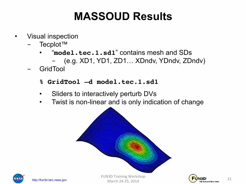
MASSOUD Results
21
• Visual inspection - Tecplot™
• “model.tec.1.sd1” contains mesh and SDs - (e.g. XD1, YD1, ZD1… XDndv, YDndv, ZDndv)
- GridTool
% GridTool –d model.tec.1.sd1!
• Sliders to interactively perturb DVs • Twist is non-linear and is only indication of change
FUN3D Training Workshop March 24-‐25, 2014

http://fun3d.larc.nasa.gov
Twist Vector
Twist Vector
What Could Go Wrong (1 of 2)
22
• Failure … check “GP.log” • Design locations must be defined to bound all target mesh nodes
FUN3D Training Workshop March 24-‐25, 2014

http://fun3d.larc.nasa.gov
What Could Go Wrong (2 of 2)
23
• Design locations must be defined to bound all target mesh nodes
FUN3D Training Workshop March 24-‐25, 2014
C1
C2
C3
C4
C7
C10
C13
C14
C6
C9
C12
C15
“cx”
“cy”
“cy” does not bound tip nodes with full precision

http://fun3d.larc.nasa.gov
MASSOUD User Defined Variables
24
• New variables as linear combination of MASSOUD variables
FUN3D Training Workshop March 24-‐25, 2014
VariablesDesign Defined- User
VariablesDesign MASSOUD
i
j
j
i
ij
PV
VP
PR
VR
∂
∂
∂
∂=
∂
∂
⎥⎥⎥⎥⎥⎥⎥⎥
⎦
⎤
⎢⎢⎢⎢⎢⎢⎢⎢
⎣
⎡
∂
∂
∂
∂
∂
∂
∂
∂
∂
∂
∂
∂∂
∂
∂
∂
∂
∂
max
max
max
2
max
1
2
max
2
2
2
1
1
max
1
2
1
1
j
i
jj
i
i
VP
VP
VP
VP
VP
VP
VP
VP
VP
!
""""
!
!
10005.0110005.01
Location) Chord-(Mid 2/)((Chord)
11
10
2
1
321
1123
1102
1101
VVVV
PPP
VVPVVPVVP
−
==
+=
−=
M6.usd
http://fun3d.larc.nasa.gov
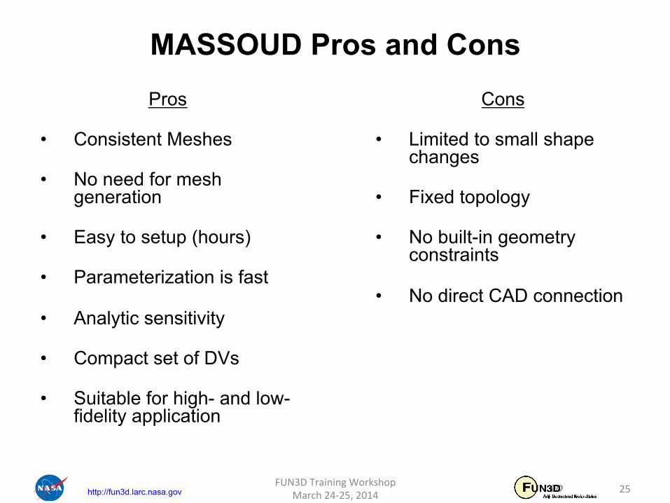
MASSOUD Pros and Cons
25
Pros
• Consistent Meshes
• No need for mesh generation
• Easy to setup (hours)
• Parameterization is fast
• Analytic sensitivity
• Compact set of DVs
• Suitable for high- and low- fidelity application
FUN3D Training Workshop March 24-‐25, 2014
Cons
• Limited to small shape changes
• Fixed topology
• No built-in geometry constraints
• No direct CAD connection

http://fun3d.larc.nasa.gov
BandAids
26
• Aerodynamic Shape Parameterization based on Free-Form Deformation
• General application based on free-form deformation - Handles complex shapes - DVs are not classic aerodynamic parameters
FUN3D Training Workshop March 24-‐25, 2014

http://fun3d.larc.nasa.gov
BandAids Key Ideas
27
1. Parameterize surface mesh - Avoids mesh regeneration
2. Use FFD to represent shape perturbations - Automates surface parameterization
3. Parameterize changes in shape perturbation, not the shape itself - Reduces the number of design variables
FUN3D Training Workshop March 24-‐25, 2014
http://fun3d.larc.nasa.gov
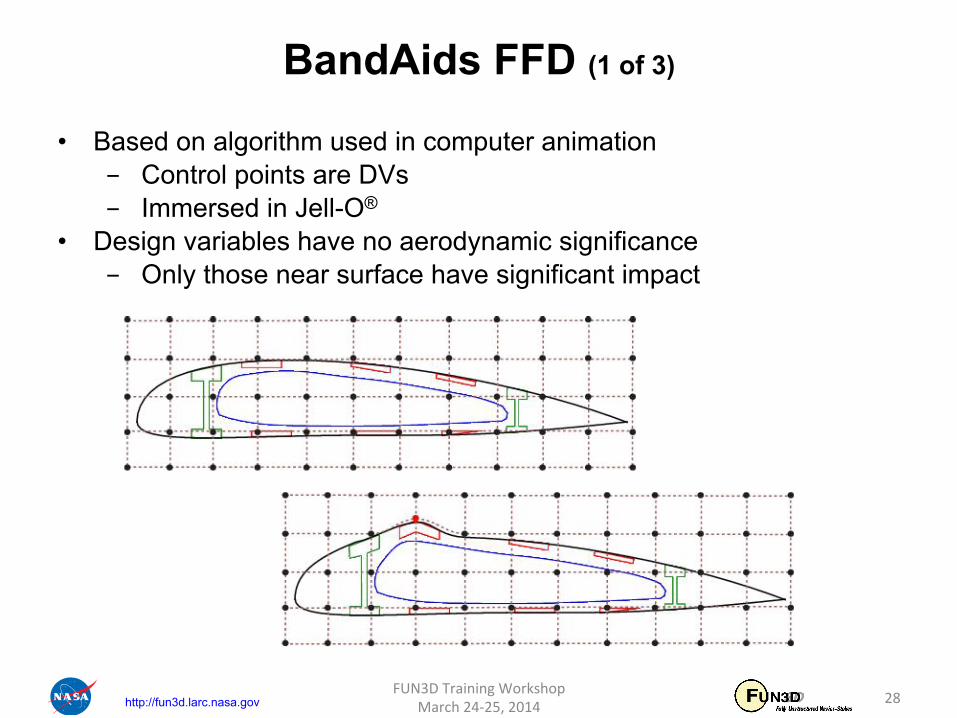
BandAids FFD (1 of 3)
28 FUN3D Training Workshop March 24-‐25, 2014
• Based on algorithm used in computer animation - Control points are DVs - Immersed in Jell-O®
• Design variables have no aerodynamic significance - Only those near surface have significant impact

http://fun3d.larc.nasa.gov
BandAids FFD (2 of 3)
• Many more control points in 3D - Only those near surface have impact on surface
FUN3D Training Workshop April 27-‐29, 2010 29

http://fun3d.larc.nasa.gov
• Equivalent 3D bi-variant form of tri-variant FFD - Collapse CPs onto surface
• Move CP moves surface underneath - Number of DVs reduced from N3 to N2
- 4 sided Bandaid marking surface over geometry • Moves only surface to which it is collapsed
- No MDO
BandAids FFD (3 of 3)
FUN3D Training Workshop April 27-‐29, 2010 30

http://fun3d.larc.nasa.gov
BandAids Parameterizes Changes
• Shape changes are small - Can be represented with fewer CPs than surface
• Maintains surface mesh character/quality
FUN3D Training Workshop April 27-‐29, 2010 31
NURBS control points for camber & thickness ( ) ( )b
n n nr v r r v= + ΔBaseline surface mesh
Design variable vector
Surface mesh point
Shape changes

http://fun3d.larc.nasa.gov
BandAids Installation
32
• Distributed as source code
- Single Makefile uses GNU C compiler (gcc) • Any localization must be done manually
- Creates a single executable • `bandAids` parameterization and deformation
FUN3D Training Workshop March 24-‐25, 2014

http://fun3d.larc.nasa.gov
• Create structured marking surface - Marks portion of geometry to parameterize - Can span multiple geometry surfaces
Marking Surface
(PLOT3D)
Surface Mesh (Tecplot™)
BandAids Marking Surfaces (1 of 2)
FUN3D Training Workshop April 27-‐29, 2010 33

http://fun3d.larc.nasa.gov
BandAids Marking Surfaces (1 of 2)
• Marking surface interpolated by reference with n x m CPs - n x m DVs
FUN3D Training Workshop April 27-‐29, 2010 34
U, i V, j
1 2
3 4
5
6
7 8
9 10
11
12 13
14 15
16 17
18 19
20

http://fun3d.larc.nasa.gov
BandAids Execution
% bandAids inMesh.plt \ inDesignSurf.p3d \ output \ numDesignInU \ numDesignInV \ [tol]!
• “inMesh.plt” target mesh in Tecplot™ format • “inDesignSurf.p3d” marking surface in PLOT3D format • “outfile” output file name prefix • “numDesignInU” number of design variables in U-direction • “numDesignInV” number of design variables in V-direction • “tol” optional, max gap between mesh and marking surface
FUN3D Training Workshop April 27-‐29, 2010 35

http://fun3d.larc.nasa.gov
BandAids Output
• Execution produces seven files: - “output.bandaid”
• All non-zero shape information!• Read directly by FUN3D
- “output.distance.plt” • Tecplot™ file with the surface mesh including the distance
between the surface mesh and marking surface!- “output.distanceSD.plt”
• Tecplot™ file containing surface mesh and sensitivity data!- “bandAidsSample.dvs”
• Template for input design variable file - “bandAidsAll.usd”, “bandAidsCol.usd”, and
“bandAidsRow.usd” • Used for linking design variables
FUN3D Training Workshop April 27-‐29, 2010 36

http://fun3d.larc.nasa.gov
BandAids Deformation
• Not necessary with FUN3D - Useful for validation
• Execute bandAids with –deformMesh!
% bandAids -deformMesh \ output.distanceSD.plt \ my.dvs \ new.plt!
• “output.distanceSD.plt” - Tecplot™ file containing surface mesh and sensitivity data
• “my.dvs” - Input DV perturbations
• “new.plt” - Deformed surface mesh
FUN3D Training Workshop April 27-‐29, 2010 37
http://fun3d.larc.nasa.gov
BandAids Results
FUN3D Training Workshop April 27-‐29, 2010 38
• Visual inspection - Tecplot™
• “output.distanceSD.plt” contains mesh and SDs - (e.g. XD1, YD1, ZD1… XDndv, YDndv, ZDndv)
- GridTool
% GridTool –d output.distanceSD.plt!
• Sliders to interactively perturb DVs • Twist is non-linear and is only indication of change

http://fun3d.larc.nasa.gov
BandAids Pros and Cons
39
Pros
• General Application
• Consistent Meshes
• No need for mesh generation
• Easy to setup (hours)
• Parameterization is fast
• Analytic sensitivity
• Compact set of DVs
• Suitable for high- and low- fidelity application
FUN3D Training Workshop March 24-‐25, 2014
Cons
• Non-intuitive DVs
• Limited to small shape changes
• No built-in geometry constraints
• No direct CAD connection

http://fun3d.larc.nasa.gov
What We Learned
• MASSOUD parameterizes with aerodynamic parameters - Best applied to aerodynamic shapes
• BandAids provides general application - Albeit w/o intuitive parameters
• Both mesh based parameterization • Both tools parameterize shape changes not shape
- Reduces number of DVs • Both provide mesh perturbation with SDs suitable for FUN3D
FUN3D Training Workshop April 27-‐29, 2010 40
Recommended