7/30/2019 Full 43511
http://slidepdf.com/reader/full/full-43511 1/14
U.P.B. Sci. Bull., Series D, Vol. 73, Iss. 2, 2011 ISSN 1454-2358
CAD DESIGN AND ANALYTICAL MODEL OF A TWELVE
BAR WALKING MECHANISM
Florina MOLDOVAN1, Valer DOLGA
2, Ovidiu CIONTOŞ
3, Cristian POP
4
Aceast ă lucrare prezint ă o abordare general ă privind proiectarea unui robot
mobil păşitor bazat ă pe aspecte specifice mediului mecatronic cum ar fi proiectarea
de tip CAD. Modelul analitic şi simularea mecanismului păşitor utilizat pentru
construc ţ ia unei structuri de robot păşitor sunt de asemenea descrise. Metoda
conturului vectorial şi metoda geometrică simpl ă sunt utilizate pentru studiul cinematic direct.
This paper presents a general approach to design of walking robot based
upon aspects regarding mechatronic environment such as CAD design. The analyticmodel and simulation of the walking mechanism that is used for building a walking
robot structure is also described. The vector loop and simple geometric method are
used for studying forward kinematics.
Keywords: Mechatronics, CAD design, Walking robot, Kinematics, Vector loop.
1. Introduction
The concept of mechatronic includes many types of research fields due to
the fact its goal is to study and develop different useful applications including
modern machines such as walking robots. Mechatronics is a complex area that
combines with success mechanical field with electronics, control systems and
embedded software fields. A general overview regarding the main components of
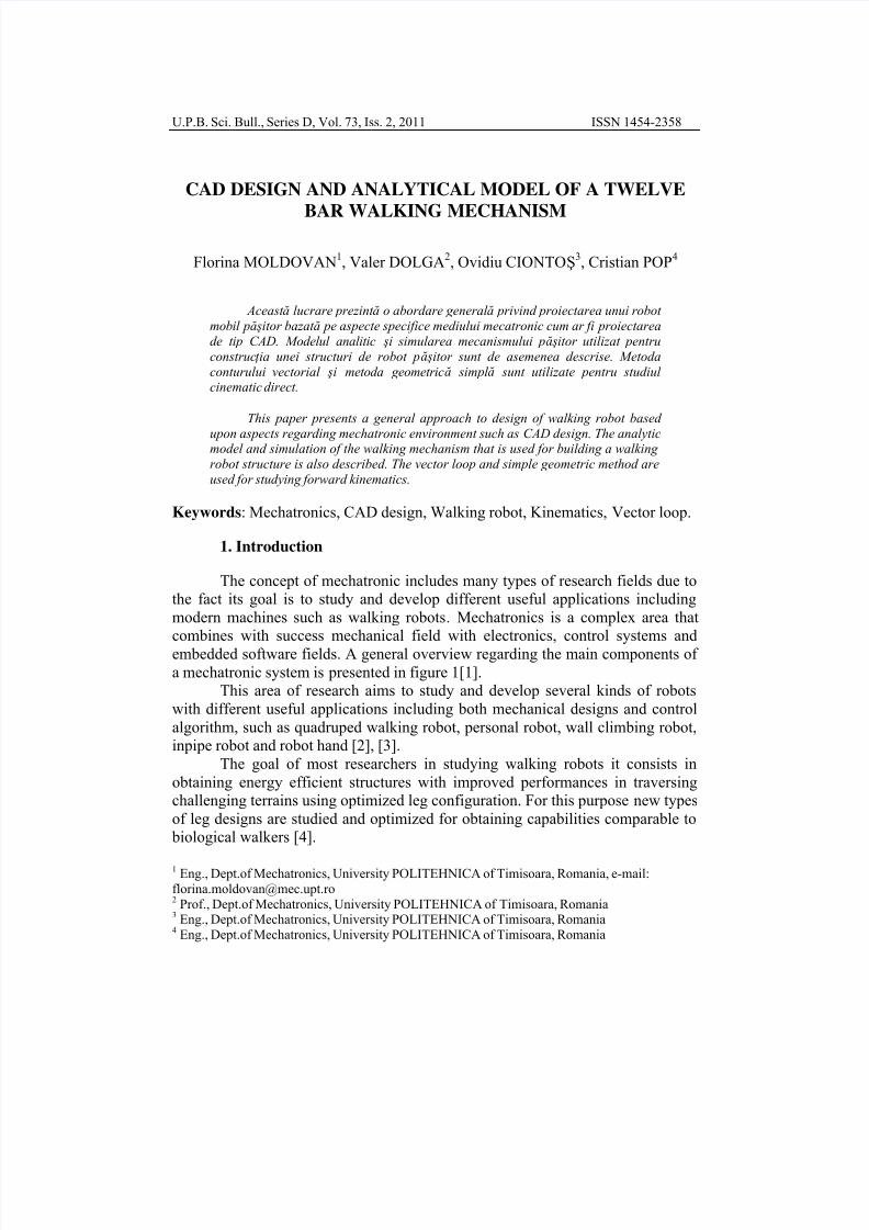
a mechatronic system is presented in figure 1[1].
This area of research aims to study and develop several kinds of robots
with different useful applications including both mechanical designs and control
algorithm, such as quadruped walking robot, personal robot, wall climbing robot,
inpipe robot and robot hand [2], [3].
The goal of most researchers in studying walking robots it consists in
obtaining energy efficient structures with improved performances in traversing
challenging terrains using optimized leg configuration. For this purpose new types
of leg designs are studied and optimized for obtaining capabilities comparable to
biological walkers [4].
1Eng., Dept.of Mechatronics, University POLITEHNICA of Timisoara, Romania, e-mail:
Prof., Dept.of Mechatronics, University POLITEHNICA of Timisoara, Romania3
Eng., Dept.of Mechatronics, University POLITEHNICA of Timisoara, Romania4
Eng., Dept.of Mechatronics, University POLITEHNICA of Timisoara, Romania
7/30/2019 Full 43511
http://slidepdf.com/reader/full/full-43511 2/14
Florina Moldovan, Valer Dolga, Ovidiu Ciontos , Cristian Pop36
A new type of walking mechanism design introduced by Dutch physicist
and kinetic sculptor Theo Jansen it consists of a twelve bar linkage powered by
the wind that walks similar to a crab and it appears in studies of few researchers
[5], [6] and [7].
The present paper is structured around four parts. The first part consists in
a short introduction; the second part describes how a walking robot can be a part
of a mechatronic system and presents the main characteristics of a mechatronic
system. The third part deals with the methods used for studying a new type of
walking mechanism and highlight the design of the leg structure based upon the
CAD design and forward kinematics and finally the fourth part consists in
conclusions.
Fig. 1. The main components of a mechatronic system
2. Walking robot as part of mechatronic system
2.1 Classification
Walking robots developed in the field of robotics research that are using
legs for traveling have few advantages instead wheel locomotion: less energy
consumption, no need for roads, capable to cross obstacles, the contact with soil is
minimized at a discrete point, don’t destroy surfaces of the ground, climbing
abilities and maintaining the body at a specific height during walking. A short
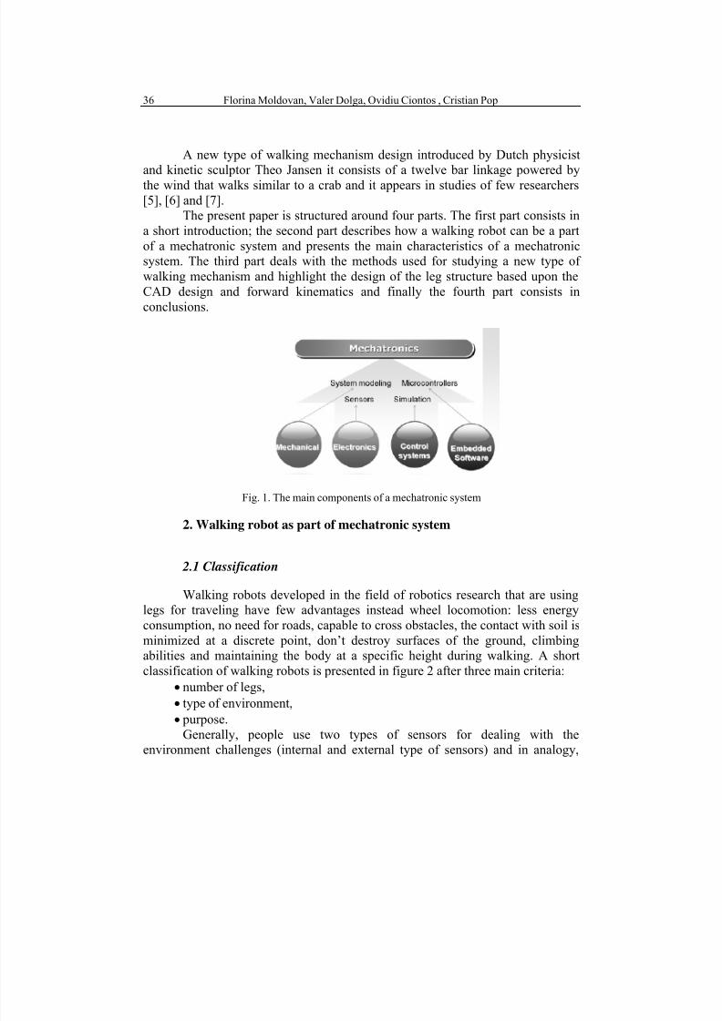
classification of walking robots is presented in figure 2 after three main criteria:
• number of legs,
• type of environment,
• purpose.Generally, people use two types of sensors for dealing with the
environment challenges (internal and external type of sensors) and in analogy,
7/30/2019 Full 43511
http://slidepdf.com/reader/full/full-43511 3/14
CAD design and analytical model of a twelve bar walking mechanism 37
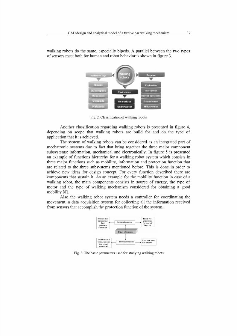
walking robots do the same, especially bipeds. A parallel between the two types
of sensors meet both for human and robot behavior is shown in figure 3.
Fig. 2. Classification of walking robots
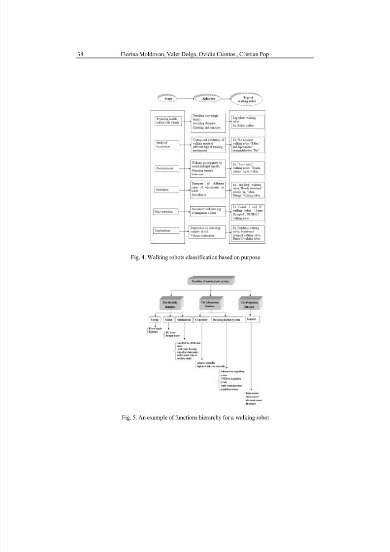
Another classification regarding walking robots is presented in figure 4,
depending on scope that walking robots are build for and on the type of
application that it is achieved.
The system of walking robots can be considered as an integrated part of
mechatronic systems due to fact that bring together the three major component
subsystems: information, mechanical and electronically. In figure 5 is presented
an example of functions hierarchy for a walking robot system which consists in
three major functions such as mobility, information and protection function that
are related to the three subsystems mentioned before. This is done in order to
achieve new ideas for design concept. For every function described there are
components that sustain it. As an example for the mobility function in case of awalking robot, the main components consists in source of energy, the type of
motor and the type of walking mechanism considered for obtaining a good
mobility [8].
Also the walking robot system needs a controller for coordinating the
movement, a data acquisition system for collecting all the information received
from sensors that accomplish the protection function of the system.
Fig. 3. The basic parameters used for studying walking robots
7/30/2019 Full 43511
http://slidepdf.com/reader/full/full-43511 4/14
Florina Moldovan, Valer Dolga, Ovidiu Ciontos , Cristian Pop38
Fig. 4. Walking robots classification based on purpose
Fig. 5. An example of functions hierarchy for a walking robot

7/30/2019 Full 43511
http://slidepdf.com/reader/full/full-43511 5/14
CAD design and analytical model of a twelve bar walking mechanism 39
2.2 The basic parameters in the study of walking robots
In a similar way it can be obtained the other values for the position anglesand the coordinates for each point that belongs to the corresponding element.
Among the basic parameters in the study of walking robots the most
important is the type of walking which determine other parameters such as:
stability, number of legs, leg configuration and method of control. In figure 6 is
presented a chart that illustrates the main parameters for studying walking robot.
This chart emphasizes the most important parameter without showing the link
between it and the rest of parameters.
The investigated mechanism presents:
• a bio inspired leg configuration;
• at least six legs which offer a great stability during walking;
•
optimized leg proportions achieved and tested by the inventor;• a low value of the moment of inertia and torque due to the slow
motion;
• articulated legs that help overcome obstacles of certain size.
The walking mechanisms used as reliance for obtaining a specific mobility
of the robots are the primary aims of the optimum constructive analysis and offer
different advantages regarding manoeuvrability, stability and dynamics. For this
reason, researchers are seeking for solution in real world and study the locomotion
and behaviour process, the control methods and leg configuration of living
creatures which achieved great performances during the evolution [9], [10].
Fig. 6. Walking robots classification based on purpose
7/30/2019 Full 43511
http://slidepdf.com/reader/full/full-43511 6/14
Florina Moldovan, Valer Dolga, Ovidiu Ciontos , Cristian Pop40
3. Study of the walking robot proposed
The present investigated mechanism studied here in order to design and build a new type of walking robot was introduced around 90’s by Dutch physicist
and kinetic sculptor Theo Jansen similar to the one presented in figure 7, which is
designed for analyzing the possibility of using this type of leg configuration in
building a walking robot. The proportions of the leg were established with help of
evolutionary algorithms which perform well approximating solutions based upon
an evolution process similar to natural one. It is necessary to initially identify the
objective functions of the investigated system and then to apply an optimization
method for obtaining the best solution before building a real model [11], [12].
There are few major steps that should be accomplish during the research
stage for building a new model of walking robot based on Theo Jansen walking
mechanism:
• kinematic analysis of the mechanism;
• kinetostatic and dynamic analysis;
• optimal synthesis;
• structural analysis;
• simulation of the new optimal structure obtained;
• the design of the prototype.
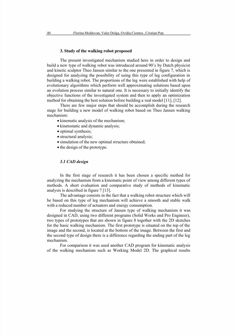
3.1 CAD design
In the first stage of research it has been chosen a specific method for analyzing the mechanism from a kinematic point of view among different types of
methods. A short evaluation and comparative study of methods of kinematic
analysis is described in figure 7 [13].
The advantage consists in the fact that a walking robot structure which will
be based on this type of leg mechanism will achieve a smooth and stable walk
with a reduced number of actuators and energy consumption.
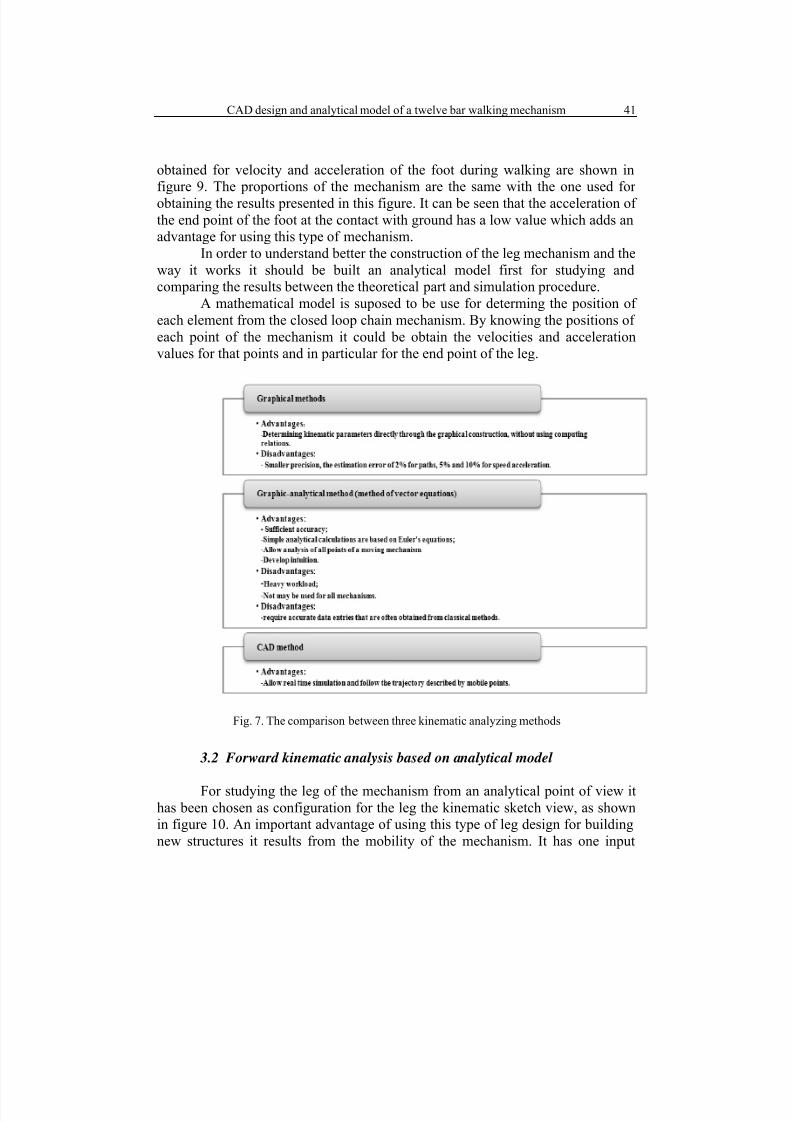
For studying the structure of Jansen type of walking mechanism it was
designed in CAD, using two different programs (Solid Works and Pro Engineer),
two types of prototypes that are shown in figure 8 together with the 2D sketches
for the basic walking mechanism. The first prototype is situated on the top of the
image and the second, is located at the bottom of the image. Between the first and
the second type of design there is a difference regarding the ending part of the legmechanism.
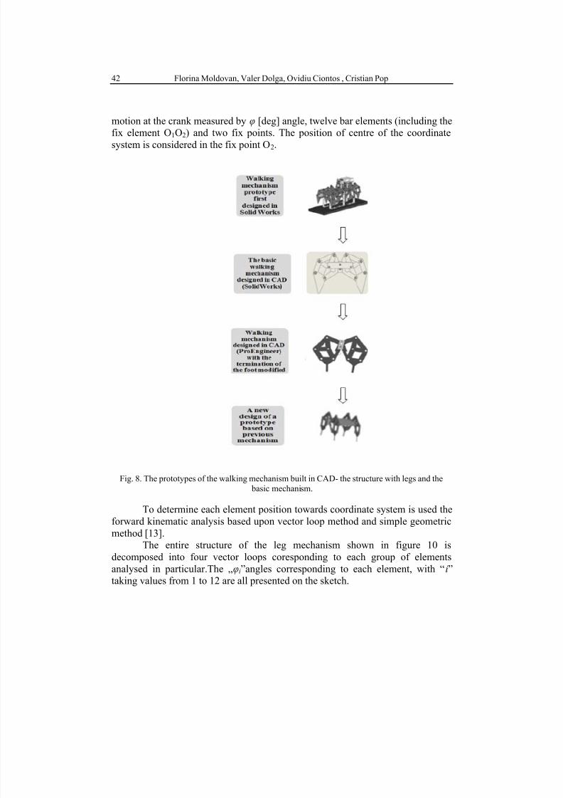
For comparison it was used another CAD program for kinematic analysis
of the walking mechanism such as Working Model 2D. The graphical results
7/30/2019 Full 43511
http://slidepdf.com/reader/full/full-43511 7/14
CAD design and analytical model of a twelve bar walking mechanism 41
obtained for velocity and acceleration of the foot during walking are shown in
figure 9. The proportions of the mechanism are the same with the one used for
obtaining the results presented in this figure. It can be seen that the acceleration of
the end point of the foot at the contact with ground has a low value which adds an
advantage for using this type of mechanism.
In order to understand better the construction of the leg mechanism and the
way it works it should be built an analytical model first for studying and
comparing the results between the theoretical part and simulation procedure.
A mathematical model is suposed to be use for determing the position of
each element from the closed loop chain mechanism. By knowing the positions of
each point of the mechanism it could be obtain the velocities and acceleration
values for that points and in particular for the end point of the leg.
Fig. 7. The comparison between three kinematic analyzing methods
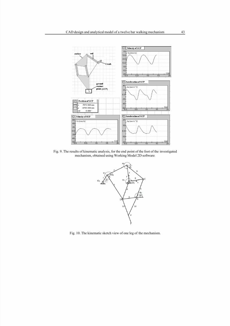
3.2 Forward kinematic analysis based on analytical model
For studying the leg of the mechanism from an analytical point of view ithas been chosen as configuration for the leg the kinematic sketch view, as shown
in figure 10. An important advantage of using this type of leg design for building
new structures it results from the mobility of the mechanism. It has one input
7/30/2019 Full 43511
http://slidepdf.com/reader/full/full-43511 8/14
Florina Moldovan, Valer Dolga, Ovidiu Ciontos , Cristian Pop42
motion at the crank measured by φ [deg] angle, twelve bar elements (including the
fix element O1O2) and two fix points. The position of centre of the coordinate
system is considered in the fix point O2.
Fig. 8. The prototypes of the walking mechanism built in CAD- the structure with legs and the
basic mechanism.
To determine each element position towards coordinate system is used the
forward kinematic analysis based upon vector loop method and simple geometric
method [13].
The entire structure of the leg mechanism shown in figure 10 is
decomposed into four vector loops coresponding to each group of elementsanalysed in particular.The „φi”angles corresponding to each element, with “i”
taking values from 1 to 12 are all presented on the sketch.
7/30/2019 Full 43511
http://slidepdf.com/reader/full/full-43511 9/14
CAD design and analytical model of a twelve bar walking mechanism 43
Fig. 9. The results of kinematic analysis, for the end point of the foot of the investigated
mechanism, obtained using Working Model 2D software.
Fig. 10. The kinematic sketch view of one leg of the mechanism.
7/30/2019 Full 43511
http://slidepdf.com/reader/full/full-43511 10/14
Florina Moldovan, Valer Dolga, Ovidiu Ciontos , Cristian Pop44
The entire mechanism structure consists in only one DOF and revolute
joints.
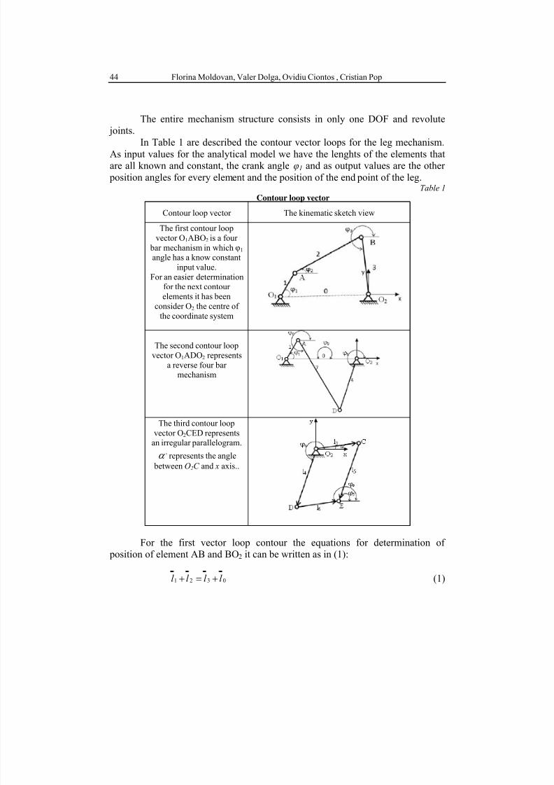
In Table 1 are described the contour vector loops for the leg mechanism.
As input values for the analytical model we have the lenghts of the elements that
are all known and constant, the crank angle φ1 and as output values are the other
position angles for every element and the position of the end point of the leg.Table 1
Contour loop vector
Contour loop vector The kinematic sketch view
The first contour loop
vector O1ABO2 is a four
bar mechanism in which φ1 angle has a know constant
input value.
For an easier determinationfor the next contour
elements it has been
consider O2 the centre of
the coordinate system
The second contour loop
vector O1ADO2 represents
a reverse four bar mechanism
The third contour loop
vector O2CED representsan irregular parallelogram.
,α represents the angle
between O2C and x axis..
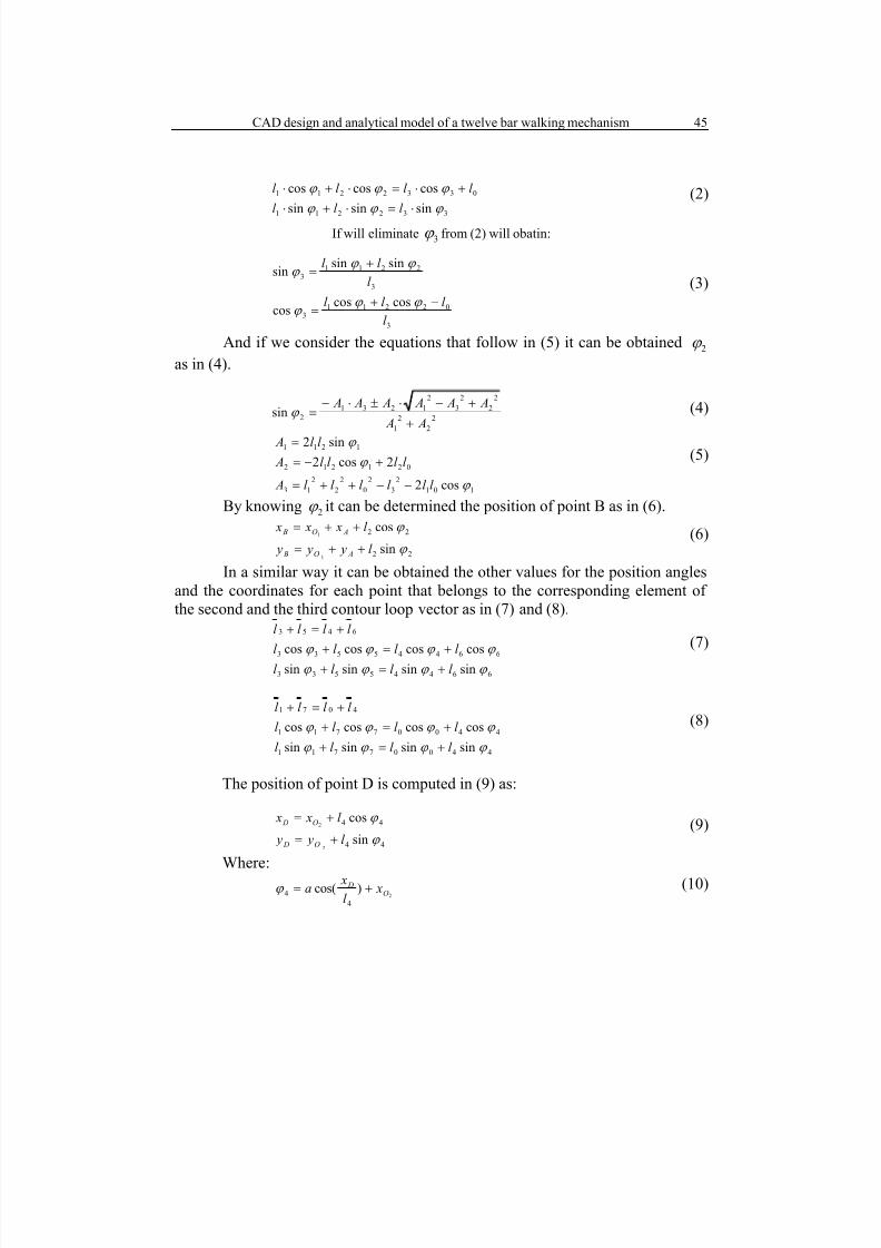
For the first vector loop contour the equations for determination of
position of element AB and BO2 it can be written as in (1):
0321 l l l l +=+ (1)
7/30/2019 Full 43511
http://slidepdf.com/reader/full/full-43511 11/14
CAD design and analytical model of a twelve bar walking mechanism 45
332211
0332211
sinsinsin
coscoscos
ϕ ϕ ϕ
ϕ ϕ ϕ
⋅=⋅+⋅
+⋅=⋅+⋅
l l l
l l l l (2)
If will eliminate 3ϕ from (2) will obatin:
3
022113
3
22113
coscoscos
sinsinsin
l
l l l
l
l l
−+=
+=
ϕ ϕ ϕ
ϕ ϕ ϕ
(3)
And if we consider the equations that follow in (5) it can be obtained 2ϕ
as in (4).
2
2
2
1
2
2
2
3
2
1231
2sin A A
A A A A A A
+
+−⋅±⋅−=ϕ (4)
101
2
3
2
0
2
2
2
13
021212
1211
cos2
2cos2
sin2
ϕ
ϕ
ϕ
l l l l l l A
l l l l A
l l A
−−++=
+−=
=(5)
By knowing 2ϕ it can be determined the position of point B as in (6).
22
22
sin
cos
1
1
ϕ
ϕ
l y y y
l x x x
AO B
AO B
++=
++=(6)
In a similar way it can be obtained the other values for the position angles
and the coordinates for each point that belongs to the corresponding element of
the second and the third contour loop vector as in (7) and (8).
66445533
66445533
6453
sinsinsinsin
coscoscoscos
ϕ ϕ ϕ ϕ
ϕ ϕ ϕ ϕ
l l l l
l l l l
l l l l
+=+
+=+
+=+(7)
44007711
44007711
4071
sinsinsinsin
coscoscoscos
ϕ ϕ ϕ ϕ
ϕ ϕ ϕ ϕ
l l l l
l l l l
l l l l
+=+
+=+
+=+(8)
The position of point D is computed in (9) as:
44
44
sin
cos
2
2
ϕ
ϕ
l y y
l x x
O D
O D
+=
+=(9)
Where:
2)cos(
4
4 O D xl
xa +=ϕ (10)

7/30/2019 Full 43511
http://slidepdf.com/reader/full/full-43511 12/14
Florina Moldovan, Valer Dolga, Ovidiu Ciontos , Cristian Pop46
In a similar manner can be computed the coordinates for point C. Knowing
the positions of the C and D points it can be determine the position of point E as
in (11):
DE y y x x
CE y y x x
D E D E
C E C E
=−+−
=−+−
22
22
)()(
)()( (11)
Similar, if we know the position of point D and E it can be computed the
position for points p and F as in (12):
DF y y x x
EF y y x x
D F D F
E F E F
=−+−
=−+−
22
22
)()(
)()( (12)
The position analysis ends when the coordinates for the end point of the
leg F are known.Locomotion systems such as walking robots are capable to maintain their
own energy systems during the equilibrium phase and can be considered as a
conservative system defined by a constant total mechanical energy [14].
Considering the twelve bar walking mechanism analyzed in this paper as a
conservative mechanical system and characterized by conservative forces, the law
of conservation of energy is:
1,12il
E F
m F l
i
p
i
iii
=∂
∂−=
=
,
/
(13)
Where il represents the vector of lengths for each element, i F the forces
that act on each element, im the masses and p E the potential energy of the
system.
The Lagrangian function, L, for a system consists in the difference
between the kinetic ( c E ) and potential energies expressed as a function of
positions and velocities described in (14). An important property of the
Lagrangian formulation is that it can be used to obtain the equations of motion of
a system in any set of coordinates, not just the standard Cartesian coordinates,
through the Euler-Lagrange equation as in (15) [14]:
)(2
1),(
,...,
.2
1
.
.
12
.
1
.
i pii
i
j
pcii
i
l E l m E E l l L
l l l
−=−=
=
∑=
(14)
7/30/2019 Full 43511
http://slidepdf.com/reader/full/full-43511 13/14
CAD design and analytical model of a twelve bar walking mechanism 47
0)( =−=
∂
∂−
∂
∂iii
ii
F l m
l
L
l
L
dt
d (15)
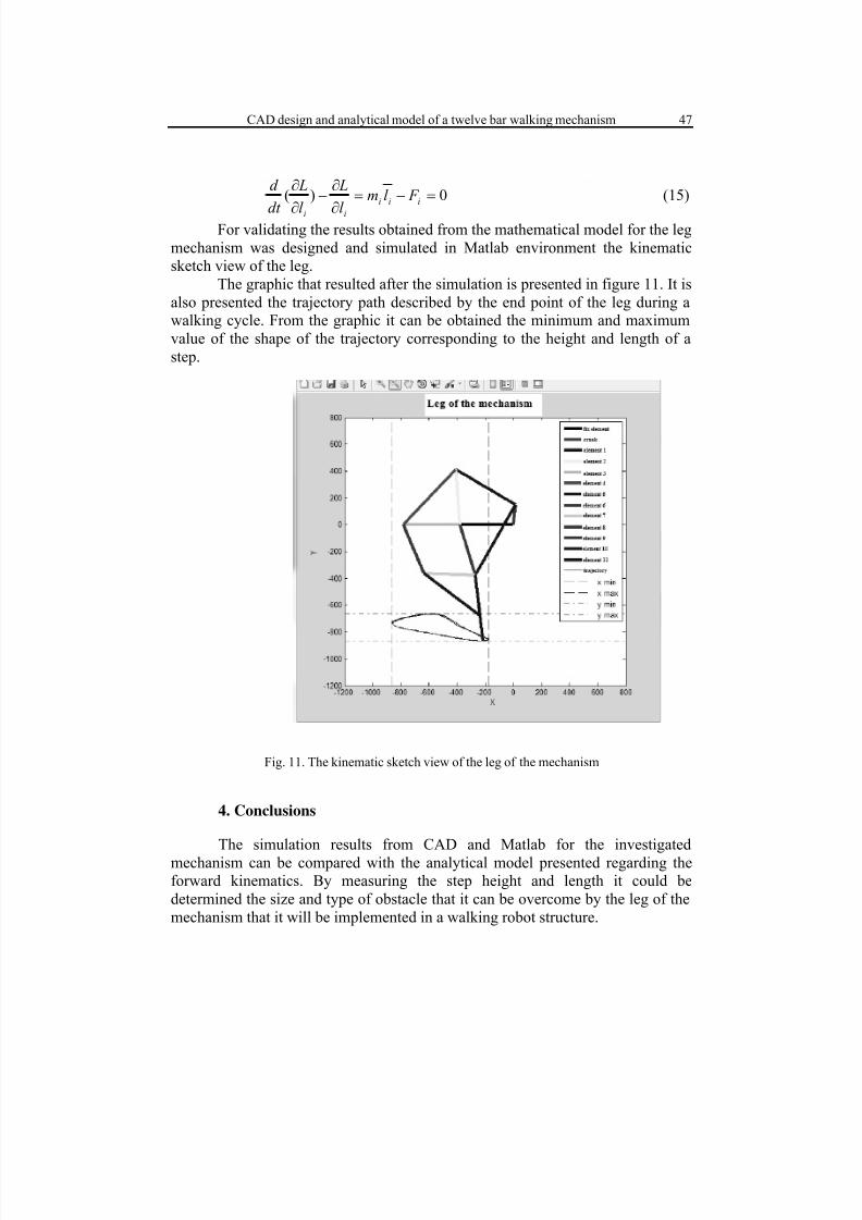
For validating the results obtained from the mathematical model for the leg
mechanism was designed and simulated in Matlab environment the kinematic
sketch view of the leg.
The graphic that resulted after the simulation is presented in figure 11. It is
also presented the trajectory path described by the end point of the leg during a
walking cycle. From the graphic it can be obtained the minimum and maximum
value of the shape of the trajectory corresponding to the height and length of a
step.
Fig. 11. The kinematic sketch view of the leg of the mechanism
4. Conclusions
The simulation results from CAD and Matlab for the investigated
mechanism can be compared with the analytical model presented regarding the
forward kinematics. By measuring the step height and length it could be
determined the size and type of obstacle that it can be overcome by the leg of the
mechanism that it will be implemented in a walking robot structure.

7/30/2019 Full 43511
http://slidepdf.com/reader/full/full-43511 14/14
Florina Moldovan, Valer Dolga, Ovidiu Ciontos , Cristian Pop48
Inverse kinematics and dynamics of the mechanism it will be analyzed
further. Also, it is necessary, as a future research, to optimise the structure of the
leg in order to achieve a reduced level of energy consumption during walking and
of the impact at the contact with the ground.
Acknowledgement
This work was partially supported by the strategic grant
POSDRU/88/1.5/S/50783, Project ID50783 (2009), co-financed by the European
Social Fund – Investing in People, within the Sectoral Operational Programme
Human Resources Development 2007 – 2013.
R E F E R E N C E S
[1]. Valer Dolga, Proiectarea sistemelor mecatronice (Mechatronic systems design) 244-
263.Politehnica, Timisoara, 2007.
[2]. I.Maniu, C. Rădulescu, I. Bogdanov, Ş .Varga,V. Dolga, V.Ciupe, Robotică. Aplicaţii
robotizate ( Robotics. Robotical applications),Editura Politehnica, Timişoara, 2009.[3]. I. Popescu, Mecanisme-Noi algoritmi şi programe (Mechanisms-New algorithms and
programs) , 317- 338, Editura Sitech, Craiova, 1997.
[4]. M.Buehler , A. Cocosco and Other , Stable Open Loop Walking in Quadruped Robots withStick Legs , IEEE Int. Conf. Robotics and Automation , 2348-2353, 1999.
[5]. D.Giesbrecht, C. Qiong Wu, Dynamics of Legged Walking Mechanism “Wind Beast”,
Department of Mechanical and Manufacturing Engineering, University of Manitoba,
California, 2010.
[6]. A.J. Ingram, A new type of walking machine. thesis , University of Johannesburg, 2006.Available at: http://152.106.6.200:8080dspace/handle/10210/598. Accessed 2010-03-10.
[7]. F. Moldovan, V. Dolga, Analysis of Jansen walking mechanism using CAD. Solid StatePhenomena (Volumes), Robotics and Automation Systems (166 - 167), 297-302,2010.
[8]. D.Shetty, , R. Kolk, Mechatronics System Design,2nd
Edition,. Cenage Learning, Stamford
USA, 2011.
[9]. J.C. Spagna, D.I. Goldman, P.C. Lin, Koditschek and R. J. Full , Distributed mechanicalfeedback in arthropods and robots simplifies control of rapid running on challenging terrain.
Institute of Physics Publishing, Bioinsp. Biomim., (2), 9–18, 2007.
[10]. S. Vat ău, Optimizarea constructiv-functionala a robotilor mobili patrupezi (Functionalconstructive optimization of quadruped mobile robots) ,thesis, Editura Politehnica, Timişoara,
2008
[11]. T.Jansen , http://www.strandbeest.com/. Accessed:2011- 03-01.[12]. L.Tudose, D. Pop, Proiectarea optimala cu algoritmi genetici (Optimal design using genetic
algorithms), 19-25. Mediamira, Cluj-Napoca, 2002.[13]. C. Duca, F. Buium, G. Paraoaru, Mecanisme (Mechanisms), 106. Gh. Asachi, Iasi, 2003.
[14] L.N. Hand, J.D. Finch, Analytical Mechanics, Cambridge University Press, Cambridge, UK,1998.
Recommended