'RES
RESARCH AND DEVELOPMENT CN TER
'eedo: a b Maryland10084
FCTIONALCHR !TRSTIC FTL-~
by AR
"A
T
A''bW
r
A 'T
A'A
-A 'AR -
PPAACHANDA> gr.
A A

.. AJR TNSDCO~ANZATIA COPONET
C6MMANbER 0
. TECINICALCQlRtCTO
,-0 ,
71 FFCWNCAROlCRJNCAG 7
tAAPRO) ANNAPOLS* 05
DEVELQIMEKT i
DEPARTNIENT , '-- -
SHiP PERFRMANCIE ~SRA~FETs
I LGIAbC DEARTENDEPARTMEN , . - M TiHEMATIQ~
'CT,
.. ~~~A [T 1RPLSO AO6nMPAR7MT OITqI ~DEPRTMN'T .
D8 E DEPRTEN
AN PT IjPARI~gN2-,
, ?9 OT4ONErTNvD 36/4bLRVC O
...............................

73 WE-' A~ '-
,A-
1. DTNRDC14E'GRSA OOMA ERESCON NANp M
M T - PERANENTJEPHNIC ~ ~ ~ ~ ~ ~ ~ ~ ~ ~ '' L AUIHYCRYXCNEUIF-NN.RCLIETFPTO-i"AL
'TH R LAS 1 AIONOR- lH-,~k,'IATNG.EPRTMNTJ/
'2. DPTNRDC.REPRS ORM~ASEFRA ESOTIN IN9MtIONO MANE NT TAPELI
NICAL Vi-AE. T ARY TA 'l OfNECUTIV L NUMENIC IVENIIAINGRLS ~
X. PTECNAL EPORTSDA AWSE INFRMALSR!gSeCPN.TAIN INFQRMiA3W!DOAPRLM. .Tk
* 9FLIMIT.D -USEAND, INTEREST., 'TI 1EVARE FRMABILY ,WORKING PAFERS' INTENDED, FOR-IN-TERNAL LiE., THE -C4 Y ANADENTIFYING 'NUMBER- WHICH 'INDIGCATEST TEIJI -TYPE -AND THENUMERICA, CO DE, OF TH ORIG N ATING'ARTM ENT;- A NY" DISTR I BUT' 16N,6U67i!pE; DT N SRDP,-pST BqE APPROVED B6Y THE HEAD O-F ThE RIGINATING, DEPARTMEN~T -ON. A CASE!.BY-CASE
BASIS"

jECUt1ITY CLASSIFICATION OF THIS PAGE (When Data Entered)~
REPORT DOCUMENTATION PAGE BEFORE COMPLETING FORM
IREPORT NUMBER 2,GOVT ACCESSION NO. 3. R ENT'S CATALOG NUMBER
DTNSRDC- 11iA M-l17 T ITL E (and Subt tieOR ERO
U. -. TI,i FITIONAL,.CHARACTERISTICS OF ILT-YAD Research and evelopment t' Tu
~ ~- AND S9TNG-PAD THRUST BEARINGS6. - PERFORMING 0G. REPORT NUMBER Z
7.A I OTATO RN UBR* V
Nathan T.1 ides
C) Thomas L.fpaugherty
9:--PER;ORMING ORGANIZATION NAME AND ADDREft -~.----- - 10 PRaGRAM EMECT PROJECT, TASKI ARE A & WORK UNIT NUMBERS
David W. Taylor Naval Ship R&D Center
Bethesda, MD 20084 See reverse side.
It. CONTROLLING OFFICE NAME AND ADDRESS
Naval Sea Systems Command /1 SepboN8(NAVSEA 05DC3) ( -13 '._NUM9ER OF PA rES_
Wahngo 9 l 0362 44P4. MNIT OGA ECY NAME & ADDRESS(11 different from Controlling Office) 15. SECURITY CLASS. (of this report)
UNCLASSIFIEDTQQ 15a. DECL ASSI FI CATION/ DOWNGRADING
SCHEDULE
16. DISTRIBUTION STATEMENT (of this Report)1
APPROVED FOR PUBLIC RELEASE; DISTRIBUTION UNLIMITED
17. DISTRIBUTION STATEMENT (of the abstract ontared in Block 20, If different from Report)
V IS. SUPPLEMENTARY NOTES
19. KEY WORDS (Continue on roverse side if necooeazy and Identify by block numb,')
Thrust BearingFrictionHydrodynamic Lubrication
'MA TRACT (Continue on reverse side if nececeery and Identify by block number)
bearings of conventional. tilt-pad and swing-pad designs. Results from the con-
ventional titpdbajtgaeused as a baseline. All tests were conducted ata fixed speed and temper~ture, while load was varied. All bearings were testedwith the pad surfaces in the centered and off-centered positions. Friction ..
(Continued on reverse side)
DD I J1AN 73 1473 EDITION OF I NOV 65 IS OBSOLETES/N 0102-LF-014-6601 UNCLASSIFIED A;
SECURITY CL ASSIFI INO IPGL ti Data g$K el)

. .. .: II L i ..~ ~ ~~.. .... ....,, ,, , , l l i i l i I I i I I ] I II _ i lT L ' . .
UNCLASSIFIEDSECURITY CLASSIFICATION OF THIS PAGE (When Date Entered)
Block 10Program Element 63561NTask Area SO 923 001Task 21257Work Unit 1102-016
k20 continued%Vresults in the hydrodynamic region compared favorably with conventional
hydrodynamic theory. The hydrodynamic load capacities of the centered
swing-pad bearing designs were 25 to 80 percent higher than that of thecentered tilt-pad bearing. Improvements in performance were observed inthe regions of hydrodynamic and mixed lubrication by off-setting thepad surfaces for both the tilt-pad and the elastomeric swing-pad designs.Breakaway friction of the laminated elastomeric swing-pad design wasabout 50 percent higher than that measured for either the conventionaltilt-pad or hybrid-pad bearing designs.
Dist r "r"t"' ,
.44)
:1]
' 1 '
UNCLASSIFIED
SICURIY CLASSIFICATION OF'THIS PAGE(hiem Dill Entered)

TABLE OF CONTENTS
Page
LIST OF FIGURES......................... .. ...... . .. . .. .. .. . . .....
LIST OF TABLES............................ ........ iv
LIST OF ABBREVIATIONS .. .............. ................ v
PLIST OF SYMBOLS. .. ................................ vi
A13STRACT................................ .. .. .... . . .. .. .. ......
ADMINISTRATIVE INFORMATION................... .. ..... . . .. .. .. .. ......
INTRODUCTION .. ...................................
ILAPPROACH .. ....................................2THEORETICAL BASIS. .. ............................... 2
TILT-PAD BEARING .. ................................ 4
SWING-PAD BEARING. .. ............................... 5
EQUIPMENT, MATERIALS, AND PROCEDURES .. ...................... 6
BEARINGS TESTED.......................... . 6. .... . .. .. .. ......
RESULTS.............................. .. ........... . .. .. .. .. .. ......
DISCUSSION. .. ................................. 13
CONCLUSIONS .. .. ..... .......................... 14
FUTURE PLANS. .. .................... ............ 15
7REFERENCES. .. ................................. 37
LIST OF FIGURES
1 -Hydrodynamic Converging Tapered Wedge .. .. ................. 16
2 -Shoe Dimensions .. .. ........ ................... 17
31 3Typical Tilt-Pad Thrust Bearing Assembly........ ............. 18
4 -Pressure Distribution on Tilt-Pad Bearing .. .. ............... 19
77,i

}
Page
5 - Swing-Pad Bearing, Centered ....... ...................... ...... 20
6 - Pressure Distribution of Swing-Pad Bearing .... .............. .... 21
7 -Hybrid-Pad Bearing 22
8 - Centered and Offset Swing-Pad Bearing ........ ................. 23
9 - Test Machine ......... . ............................. .... 24
10 - Test Bearing in Oil Tank ..... .. ....................... .... 25
11 - Test Machine Schematic ........ ........................ .... 26
12 - Tilt-Pad Assembly, Centered (After test) .... ............... .... 27
13 - Swing-Pad Assembly, Centered ...... ..................... ..... 28
14 - Hybrid-Pad Assembly, Centered .... ........................ 29
15 - Results, Tilt-Pad, Centered ........... o.......... 30
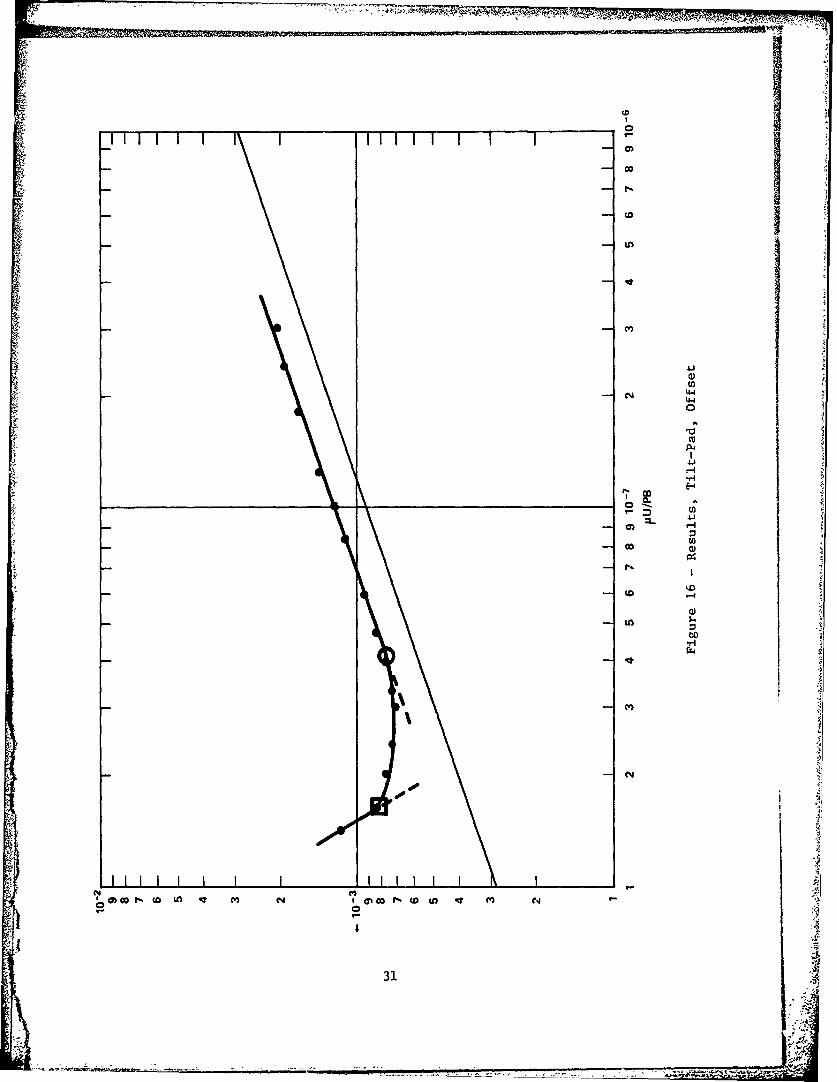
16 - Results, Tilt-Pad, Offset .......... ....................... 31
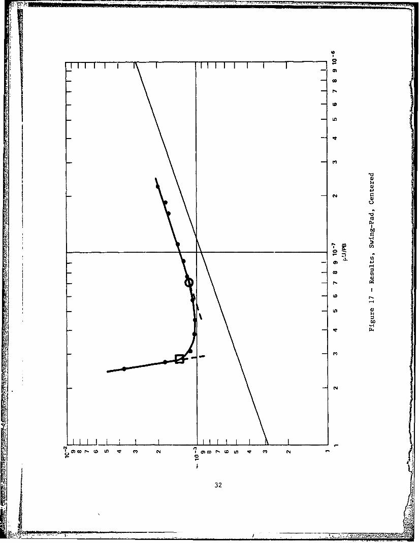
17 - Results, Swing-Pad, Centered ...... ..................... ..... 32
18 - Results, Swing-Pad, Offset ..... ..................... 33
19 - Results, Hybrid-Pad, Centered ...... ..................... .... 34
20 - Results, Hybrid-Pad, Offset. ...... ...................... .... 35
21 - Superimposed Plots ..... ...... ...... ...... 36
LIST OF TABLES
1 - Last Hydrodynamic Values .i......... .... ...... ... 10
2 - Last Transition Zone Values From Hydrodynamic
to Mixed Lubrication ...... . .......................... ii.
3 - Breakaway Coefficient of Friction ..... .. .................. . 12
iv

LIST OF ABBREVIATIONS
-C Degrees Celsius
0 oF Degrees Fahrenheit
cm Centimeter
ft Foot
in. Inch
in./s Inches per second
kPa Kilopascal
; , , lb Pound
lb-ft Pound-foot
lb-in. Pound-inch
ji m Meter
min Minute
mm Millimeter
m/s Meter pcr second
N Newton
1 i~' Nm Newton-meter
I ~psi Pounds per square inch
rpm Revolutions per minute
rms Root mean square
s Second
p1in. Microinch
pim Micrometer
v
.. ..p,

j LIST OF SYMBOLS
a (hi/h)
B Bearing pad circumferential length, cm (in.)
b Bearing pad radial length, cm (in.)
d Moment arm from P to pad centerline, cm (in.)r
F Friction force, N (ib)
Ff Force due to friction, N (lb)
f Coefficient of friction
hi Lubricant film thickness at leading edge, mm (in.)
h Lubricant minimum film thickness at trailing edge, mm (in.)0
K Function of n
K Function of flp
Mf Moment due to friction force, Nm (lb-in.)
M Moment due to pressure forces, Nm (lb-in.)P
P Average load on bearing surface, kPa (psi)avg
P Resultant pressure vector, N (ib)r
R Radius of swing, cm (in.)
U Surface speed, m/s (in./s)
W Total bearing applied load, N (lb)
x Distance from pad leading edge to pivot point, cm (in.)
n Modifying factor
P1 Absolute viscosity, poise (reyns)
vi

ABSTRACT
This report presents frictional performance ofoil-lubricated thrust bearings of conventional tilt-padand swing-pad designs. Results from the conventionaltilt-pad bearing are used as a baseline. All testswere conducted at a fixed speed and temperature, whileload was ,arieu. All bearings were tested with thepad surfaces in the centered and off-centered posi-tions. Friction results in the hydrodynamic regioncompared favorably with conventional hydrodynamic theory.The hydrodynamic load capacities of the centered swing-pad bearing designs were 25 to 80 percent higher thanthat of the centered tilt-pad bearing. Improvements inperformance were observed in the regions of hydrodynamicand mixed lubrication by off-setting the pad surfacesfor both the tilt-pad and, the elastomeric swing-paddesigns. Breakaway friction of the laminated elasto-meric swing-pad design was about 50 percent higher thanthat measured for either the conventional tilt-pad orhybrid-pad bearing designs.
ADMINISTRATIVE INFORMATION
This report covers work conducted for the Naval Sea Systems Command (NAVSEA
05DC3; formerly NAVSEA 6113) under Research, Development, Test and Evaluation Funds,
Work Request 9G002, Work Unit 1102-016.
INTRODUCTION
A primary goal of the U.S. Navy's Improved Performance Machinery Program is to
reduce the size and weight of the steam propulsion plant and associated equipment in
submarines. Such reductions are explored herein for an oil-lubricated main thrust
bearing. A basic requirement for an improved bearing is increased load capacity.The potential for increased load capacity was demonstrated in exploratory tests*
conducted on a bearing design called the "swing-pad bearing," which was invented at
David W. Taylor Naval Ship Research and Development Center (DTNSRDC), patent number
3,930,691 of 6 Jan 1976. This report includes comparison of the frictional char-
acteristics and load carrying capacity between two variations of the swing-padA4
bearing and the conventional tilt-pad bearing.
References are listed on page 37.
:

APPROACH
Friction in hydrodynamic sliding surface bearings is a function of the
viscosity of the lubricant, surface speed of the bearing, applied load, and the size
of the bearing pad. The friction of thrust bearings of tilt-pad and swing-pad
designs was measured on the same test machine and compared over a range of applied
bearing loads. The tilt-pad bearing, purchased commercially, was used as a
reference. Two swing-pad bearing designs were evaluated. All bearings were tested
with the center of tilt or swing centered and offset to one side. Comparison of
frictional results was also made with that predicted by existing theoreticalanalysis.2 The load capacities in the hydrodynamic region and in the mixed
lubrication. region of each design were compared. Breakaway experiments were con-
ducted for each design and the results compared in this report.
THEORETICAL BASIS
Theoretical analysis of hydrodynamic bearings is based upon existence of a
converging wedge such as that shown in Figure 1. Hydrodynamic theory applied to a
tapered wedge gives the following equations, according to Fuller2
h= (6iUB)) 1/2\avg/
F - bBKf -- (2)
f (3)
For the purposes of this investigation, the following values apply (see Figure 2)
B = 3.18 cm (1.25 in.)
b 2.97 cm (1.17 in.)
2

qb
b 1 1, therefore, n = 0.44I
Assuming the leading edge film thickness to be twice the trailing edge film thick-
ness, a 2, K 0.0265, and Kf - 0.773p
from (3) /
f - - (4)
PbB
combining Equations (1), (2), and (4)
.bBK Uf = PbB (5)
4 \avg
Simplifying and applying numerical values,
1 u \1/2
f -2.9 PB (6)
When plotted on log-log graph paper, the above expression yields a straight line.
Simplifying Equation (1), the following expression is obtained for the minimum film
thickness
o 06QUB)h= (7)i¢ h ° 0.264 -P (7).
3tf

I,
Hydrodynamic lubrication is said to exist as long as the bearing behaves
according to the above expressions. Full fluid separation exists between the bear-
ing and the mating runner surface and the only frictional losses are due to fluid
shear. Under these conditions. virtually no wear occurs and bearing life is
theoretically infinite. The coefficient of friction decreases in proportion to the
parameter (pU/Pb)I /2. Load is supported entirely by pressurized lubricant.
In practice, however, a limit to hydrodynamic lubrication exists. As the
parameter VIU/PR is decreased through increased load, decreased speed or viscosity
of the lubricant, the minimum film thickness of the lubricant is also reduced.
A point is reached when the height of the asperities on the bearLng a-ld runner sur-
faces exceeds the thickness of the fluid film and intermittent contact occurs. The
coefficient of friction will continue to decrease to a minimum value. The slope
will depar. from the straight line observed in the hydrodynamic region. Continued
decreases in JiU/PB will produce a sudden increase in the coefficient of friction.
This transitional region of operation, characterized by load being shared by both
asperity contacts and pressurized lubricant, is referred to as "mixed lubrication."
Further reduction in pU/PB leads to further deterioration to the point that
load is completely sup)orted by surface--to-surface contact where the lubricant no
longer separates the bearing and runner. The coefficient of friction will then be
large and reflect the frictional properties of the mating materials. This condition
is known as "boundary lubrication."
TILT-PAD BEARING
The conventional tilt-pad thrust bearing consists of individual pads usually
ranging in number from two to twelve and spaced annularly as shown in Figure 3. lt
consists of a flat sliding surface, or runner, sliding over the pads which are free
to pivot or tilt independently. The pads are usually completely immersed in the
lubricant. The tilt-pad thrust bearing was invented by Albert Kingsbury and
A.G.M. Michell in the early 1900s.
The basic theory behind the tilt-pad design is that the pivot shoe is free to
adjust itself to the optimum angle for any operating condition. Its basic loadc apacity is d44rive. ty creation of a converging wedge of lubricant in the direct-ion
of motion. Behavior Is similar to that discussed in the theoretical basis section
of this report. The pivot location may be moved to various positions across the
4
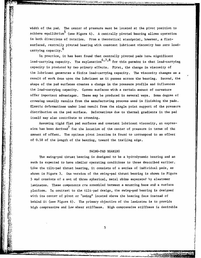
width of the pad. The center of pressure must be located at the pivot position to
achieve equilibrium5 (see Figure 4). A centrally pivoted bearing allows operation
in both directions of rotation. From a theoretical standpoint, however, a flat-
surfaced, centrally pivoted bearing with constant lubricant viscosity has zero load-~6
carrying capacity.
In practice, it has been found that centrally pivoted pads hav significant
load-carrying capacity. The explanation6 '7'8 for this paradox is that load-carrying
capacity is produced by two primary effects. First, the change in viscosity of
the lubricant generates a finite load-carrying capacity. The viscosity changes as a
result of work done upon the lubricant as it passes across the bearing. Second, the
shape of the pad surfaces creates a change in the pressure profile and influences
the load-carrying capacity. Convex surfaces with a certain amount of curvature
offer important advantages. These may be produced in several ways. Some degree of
crowning usually results from the manufacturing process used in finishing the pads.
Elastic deformations under load result from the single point support of the pressure
distribution on the pad surface. Deformations due to thermal gradients in the pad
itself may also contribute to crowning.
Assuming rigid flat pad surfaces and constant lubricant viscosity, an expres-
sion has been derived7 for the location of the center of pressure in terms of the
amount of offset. The optimum pivot location is found to correspond to an offset
of 0.58 of the length of the bearing, toward the trailing edge.
SWING-PAD BEARING
The swing-pad thrust bearing is designed to be a hydrodynamic bearing and as
such is expected to have similar operating conditions to those described earlier.
Like the tilt-pad thrust bearing, it consists of a series of individual pads, as
shown in Figure 3. One version of the swing-pad thrust bearing is shown in Figure
5 and consists of a set of three spherical, metal shims separated by elastomer
laminates. These components cre assembled between a mounting base and a surface
platform. In contrast to the tilt.-pad design, the swing-pad bearing is designed
with its center of pivot or "swing" located above the bearing face instead of
behind it (see Figure 6). The primary objective of the laminates is to provide
high compressive and low shear stiffness. High compressive stiffness is desirable
5

in practical applications to control and maintain shaft position. Low shear stiff-
ness allows the bearing surface to displace along its swing arc for formation of the
desired converging wedge.
An idealized version of the swing-pad bearing can be approximated by minimizing
the shear stiffness, while providing very high compressive stiffness. This design
is referred to as the "hybrid-pad bearing." It consists of replacing the elastomer
and metal, spherical laminates with steel balls which ride between hardened
spherical surfaces (see Figure 7).
Note that the center of pressure on the pad surface is not required to pass
through the center of swing as was required in the tilt-pad bearing analysis. For
example, if the pad surface were offset toward the leading edge (see Figure 8), a
significant moment is created by this offset which encourages a converging wedge.
The conventional theory of hydrodynamic sliding surface bearings considers onlyt
the pressure loading and location of the center of pressure on the surface of the
pads. Drag or friction forces are usually ignored. This is an acceptable procedure
when operation is clearly in the hydrodynamic region. However, as operation moves
into the transition between hydrodynamic and mixed lubrication, it becomes apparent
that the frictional forces play a more significant role. For the tilt-pad bearing
with its center of pivot located behind the pad surface, a friction force on the
surface produces a moment in a direction opposing desirable converging wedge forma-
tion (see Figure 4). For the swing-pad design with its center of swing located
above the pad surface, the friction force on the surface produces a moment in the
direction of desirable converging wedge formation (see Figure 6). Operation in the
hydrodynamic region with the same wedge angle should provide the same performance
for both the tilt-pad and swing-pad designs. The range of hydrodynamic lubrication
and mixed lubrication would be expected to be extended with proper swing-pad design
due to the location of the swing center.
EQUIPMENT, MATERIALS, AND PROCEDURES
The test machine (see Figures 9, 10, and 11) uses a hydraulic drive system
coupled to a gearbox capable of bidirectional rotation. Two disk runners are
splined on the shaft and are free to move axially in the vertical direction. Two
sets of bearing pads, each consisting of three pads located 120 degrees apart, are
loaded against the disk runners. The arrangement is very similar to an automobile
6

wE 7.
disk brake system. Loading is accomplished with hydraulic cylinders. The bearing
pads and runner assembly is submerged in a lubricant reservoir. The reservoir is
made of plexiglass to allow viewing. A heat exchanger is also incorporated to
regulate the bulk lubricant temperature.
Measured parameters are shaft speed, torque (via an in-line torquemeter),
load (via load cells and pressure gauges), and bulk lubricant temperature (via a
thermocouple).
The runner surfaces used in all tests were mild steel ground and polished cir-
cumferentially to a surface finish of 0.10 to 0.20 pm (4 to 8 pin. rms as measured] ~ in the direction of rotation. Bearing shoes were made of babbitt of the following
composition:
Tin 89.60 percent
t Lead 0.14 percent
Antimony 7.99 percent
Copper 2.16 percent
This composition is very similar to ASTM babbitt grade 2 and Navy grade 2.
The babbitt shoes (0.64 cm (0.25 in.) thick) were cemented to the bearing pads.
Two steel pins were also used to carry the shear load and maintain the relative
position of the shoe to the pad. Two sets of three pads each were mounted on load-
ing rings. The shoes were then manually polished by placing the assembly against a
rotating polishing disk. Emery paper of successively finer grades (down to 600 grit'
was used on the polishing disk and kept constantly wet to prevent clogging. Rota-
tion of the polishing wheel was always in the same direction as that of the runner
disk in the test machine. Surface finishes of 0.1 to 0.15 pm (4 to 6 pin.) rms
were achieved on the babbitt surfaces in this manner.
The two bearing sets were mounted in the test machine and the shaft rotated
at zero load and 35 rpm. Temperature of the lubricant was regulated at 500C
(1220 F). The lubricant used was 2190 TEP oil (MIL-L-17331) with a viscosity
roughly equivalent to an SAE 20 oil. Load was applied to a prescribed value and
maintained for 15 min. Torque, temperature, load, and shaft speed were recorded at
that time and load increased to the next value. The coefficient of friction was
computed.
The coefficient of friction decreases in value with increased load as long as
the bearing remains in the hydrodynamic mode. When the coefficient of friction
7

3
started increasing in value with increased load, signifying breakdown of the
hydrodynamic film and entry into mixed lubrication region, the test was stopped.
The bearings were removed for inspection and photographs were taken. The bearings
were replaced in the machine and breakaway tests were then conducted.
For breakaway tests, the drive motor and torquemeter were disconnected because
the expected static frictional torque exceeded their capacity. A torquewrench
with a follower needle was used to manually conduct this test. Load was applied
for time periods of 1 min, 5 min, 15 min, and 1 hour. The bulk oil temperature was
maintained at 500C (1220 F). At the prescribed time, the shaft was rotated using
the torquewrench. The needle follower on the scale indicated the highest torque
reached to initiate rotation. This value was recorded. Load and time under load
were increased until the limit of the torquewrench of 339 Nm (250 lb-ft) was
reached.
An offset ratio of x/B = 0.7 was tested. Some preliminary testing with the
swing-pad bearing showed that an offset of x/B = 0.7 produced the best results.
The hybrid-pad bearing was expected to have similar performance to the swing-pad
bearing; and, as such, x/B = 0.7 was adopted for it also. The coefficieht of fric-
tion and the power losses for the tilt-pad bearing are relatively constant for
x/B values ranging from 0.57 to 0.75. The minimum film thickness is reduced4 by
17 percent at x/B = 0.7. x/B = 0.7 was therefore used on this bearing as well as /
for uniformity.
BEARINGS TESTED
The swing-pad bearing was fabricated at DTNSRDC using a manufacturing technique
developed and perfected with the assistance of the Center's rubber laboratory.
The metallic components were fabricated in the machine shop.
The laminates consist of calendered sheets of Buna-N rubber v:ilcanized to the
metal parts using a specially designed mold. The hardness of the cured rubber is
55 ± 5 on the Shore A scale. The mean radius of the laminates is 5.08 cm (2.00 in.).
The bearing has four laminates. The pads were mounted 120 degrees apart on a
7.144 cm (2.813 in.) radius to center of pad. The surface area of the three padsc2 i.2
is 26.5 cm (4.1 in.
The tilt-pad bearing was purchased from Kingsbury Machine Works, Inc. It is a
three-shoe, self-aligning, equalizing bearing with a radius to 6.668 cm (2.625 in.)
8
.. ,

2 2to the pivot point. The surface area of the three pads is 79.4 cm2 (12.3 in.2
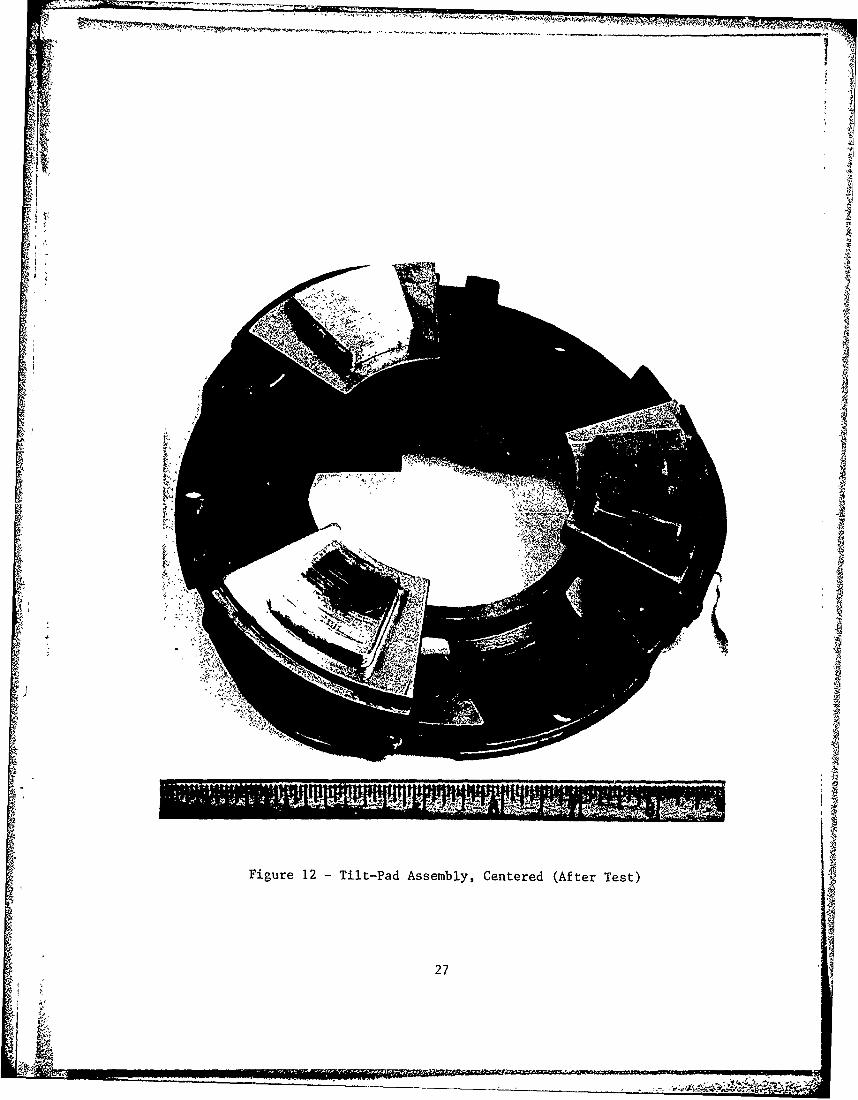
The tilt-pad was first tested as received with the larger pad surface. Babbitt
shoes identical to those used in the swing-pad were then bonded to the larger tilt-
pad shoe (Figure 12) and tests were conducted as described. Frictional results of
both arrangements were compared to data obtained in a shipboard application. The
results agreed well in all cases. Therefore, it was concluded that no experimental
error was being introduced by bonding smaller pad surfaces to the tilt-pad bearing
assembly. The swing-pad and hybrid-pad bearing assemblies are shown in Figures 13
and 14, respectively. The spherical mating surfaces of the hybrid design were
hardened to a value of 60 on the Rockwell C scale. The overall dimensions and
the "swing" radius were identical to those of the swing-pad.
I RESULTS
Test results are presented in Figures 15 through 21 and Tables I through 3.
Figures 15 through 20 present the friction data of the dynamic tests for each bear-
ing design. Figure 21 combines the curves of each of these tests for easier
comparison. The coefficient of friction calculated from the torque measurements
was plotted against the parameter ]iU/PB. These figures also include the theoretical
curve which represents hydrodynamic conditions according to Equation (6).
The friction curves appear to have three distinct regions. The first is the
region in which the experimental data are parallel to the predicted hydrodynamic
behavior. The second region is characterized by departure from parallelism with the
hydrodynamic curve, but undergoing minor changes in friction as bearing load
increases. The third region is represented by abrupt changes in the friction coeff-
icient with increased load. Each curve in Figures 15 through 20 are marked with the
following symbols: o, representing the last condition indicative of hydrodynamic
behavior; and , representing the last transition point before the onset of a
sudden increase in the coefficient of friction as load is increased. Data under
these conditions are used as a basis of comparison for each of the bearing designs
and are used in Tables 1 and 2. The load at the point marked with symbol o is
referred to as the "hydrodynamic load capacity," because it represents the highest
load obtained under hydrodynamic conditions. Breakaway friction coefficients under
2,950 kPa (428 psi) are presented in Table 3.
9
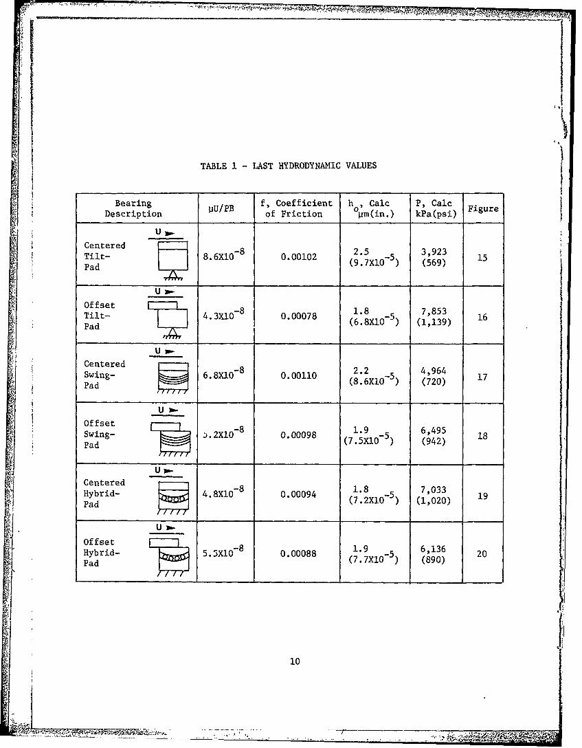
TABLE I - LAST HYDRODYNAMIC VALUES
Bearing pU/PB f, Coefficient h , Calc P, Calc FigureDescription of Friction pm(in.) kPa(psi)
Centered -8 2.5 3,923Tilt- 8.6X10(9.7X0) (569) 15~~Pad
Tilt- 4.3X-8 0.00078. 7,853Pad L (6.8XO - ) (1,139) 16
U .Centered -8-
Swing- 6.8XI0 0.00110 2.2 4, 964Pa ,(8"6XI0-5)1Pad (861) (720) 1
Offset -. 6,495Swing- .2XlO -8 0.00098 5 18Pad(7.5XI0 - (942)Pad
U-
CenteredHybrid- 4.8XI0-8 0.00094 1.8 7,033Pad (7.2X10 5) (1,020) 19! u~Offset - 1.9 6,136Hybrid- 5.5XIO - 8 0. 00088 1. 5 616 20
Pad (7.7XIO 5) (890)
10

i0
I
TABLE 2 - LAST TRANSITION ZONE VALUES FROMHYDRODYNAMIC TO MIXED LUBRICATION
Bearing pu/PB f, Coefficient P, Calc FigureDebcription of Friction kPa(psi)
U -
Centered 11,638Tilt- 2.9X10 8 0.00096 (1,6815Pad (1,688)
Pad
Offset [8 21,098Tilt- 1.6X10 8 0.00086 (3,060) 16Pad
Up,
Centered -8 12,059Swing- 2.8X0 - 0.00145 17Pad Q (1,749)
Offset 8 0028,131 18Swing- 1.2X1 - 0.00093 18Pad I~
Centered r8 19,857
Hybrid- 1.7X10 8 0.00120 (2,880) 19Pad
Offset [-20 -821,098Hybrid- 1.6X10 8 0.00090 20Pad _(3,060)
Padi
11

TABLE 3 -BREAKAWAY COEFFICIENT OF FRICTION "'tI
Bearing Average Breakaway Coefficient of
Description Friction under 2,950 kPa (428 psi)
U .
Centeredm
Tilt- 0.20Pad
UOf fset
Tilt- 0.15
Pad
UCentered
Swing- 0.30
Pad
U-
Offset
Swing- ' -- 0.29 .I Pad
Centered
Hybrid- 0.19Pad
Offset UHybrid- m0.18Pad
12
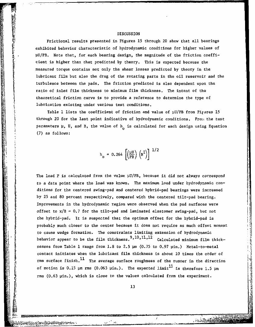
DISCUSSION
Frictional results presented in Figures 15 through 20 show that all bearings
exhibited behavior characteristic of hydrodynamic conditions for higher values of
PU/PB. Note that, for each bearing design, the magnitude of the friction coeffi-
cient is higher than that predicted by theory. This is expected because the
measured torque contains not only the shear losses predicted by theory in the
lubricant film but also the drag of the rotating parts in the oil reservoir and the
turbulence between the pads. The friction predicted is also dependent upon the
ratio of inlet film thickness to minimum film thickness. The intent of the
theoretical friction curve is to provide a reference to determine the type of
lubrication existing under various test conditions.
Table 1 lists the coefficient of friction and value of VU/PB from Figures 15
through 20 for the last point indicative of hydrodynamic conditions. Froi the test
parameters p, U, and B, the value of h is calculated for each design using Equation0
(7) as follows:
h 0.264 (B2)] 1/2
The load P is calculated from the value pU/PB, because it did not always correspond
to a data point where the load was known. The maximum load under hydrodynamic con-ditions for the centered swing-pad and centered hybrid-pad bearings were increased
by 25 and 80 percent respectively, compared with the centered tilt-pad bearing.
Improvements in the hydrodynamic region were observed when the pad surfaces wereoffset to x/B = 0.7 for the tilt-pad and laminated elastomer swing-pad, but not
the hybrid-pad. It is suspected that the optimum offset for the hybrid-pad is
probably much closer to the center because it does not require as much offset moment
to cause wedge formation. The constraints limiting extension of hydrodynamic
behavior appear to be the film thickness. Calculated minimum film thick-
nesses from Table 1 range from 1.8 to 2.5 pm (0.75 to 0.97 pin.) Metal-to-metal
contact initiates when the lubricant film thickness is about 10 times the order of
rms surface finish.11 The average surface roughness of the runner in the direction
of motion is 0.15 pm rms (0.063 pin.). The expected limit is therefore 1.5 pm
rms (0.63 pin.), which is close to the values calculated from the experiment. 4
13

The transition region from hydrodynamic behavior to the point at .' r e
coefficient increases abruptly with increased load is extended in all designs by
offsetting the pad surfaces (see Figure 21).
The coefficient of friction for the breakaway tests were unaffected by the time Iunder load. The values in Table 3 were obtained by averaging results of the four
tests; I min, 5 min, 15 min, and 1 hour under load. The friction coefficients cf
the tilt-pad and hybrid-pad are about the same. The coefficient of friction of the
swing-pad bearing is about 50 percent higher. Offsetting of the surface did not
affect the breakaway friction of any design.
Frictional results of this report did not agree with expectations based on a
1previous report for either the dynamic or breakaway experiments even though the
same basic size and design swing-pad bearing was used. It is suspected that the
type of conventional bearing used for comparison in the previous report did notrepresent its characteristic behavior.
CONCLUSIONS
Based upon a single series of tests on each of the six bearing designs, the
following conclusions are made:
(1) Below bearing unit loads of 3,900 kPa (569 psi), all bearing designst
exhibited behavior characteristic of hydrodynamic conditions.
(2) The limit for hydrodynamic behavior appears to be more dependent upon the
surface finish of the runner surface than upon bearing design.
~(3) The maximum load under hydrodynamic conditions for the centered swing-pad
and centered hybrid-pad were increased by 25 and 80 percent respectively, compared
to the tilt-pad bearing.
(4) Improvements in hydrodynamic performance of both the tilt-pad and laminatedelastomeric swing-pad bearing were observed by offsetting the pad surfaces.
(5) The transition region from hydrodynamic behavior to the point at which the
coefficient of friction increases abruptly with increased load is extended in all
designs by offsetting the pad surfaces.
(6) Variation in time of 1 to 60 min under a load of 2,950 kPa (428 psi) did
not affect the breakaway friction of any design.
(7) The breakaway coefficient of friction of the laminated elastomeric swing-
pad bearing was about 50 percent higher than that measured for either the conven-
tional tilt-pad or hybrid-pad bearing.
'ii 14

. -IF
(8) Offsetting the pad surfaces did not affect the breakaway friction of
any design.
FUTURE PLANS
No further experimental evaluation of the swing-pad bearing designs is planned.
Efforts have been focused upon development of a model for the swing-pad bearing so
that the design can be optimized. The tests described in this report were based
primarily upon previous test results. There are several parameters which appear to
11fect the performance of the swing-pad, such as the amount of offsetting of the
center of swing compared with the center of the pad, the radius of curvature of the
laminates, and the compressive and shear stiffness. An in-house effort is underway
in FY 80 to develop such a mathematical model. If successful and if optimization
looks promising, additional experiments will be needed to verify such expectations.
15

hI
i i ho
I I
Figure 1 - Hydrodynamic Converging Tapered Wedge
16

13.18 cm(1.25 in.)'
2.97cmn(1.17 in.)
7.144cm.4 (2.813 in.)
Figure 2 -Shoe Dimensions
17

w
SLIDING SURFACEOR RUNNER
ROTATION
PIVOT PADS
Figure 3 -Typical Tilt-Pad Thrust Bearing Assembly
1s

" Pr'i PRESSURE
PROFILE
i I
Ff
PIVOT POINT
Figure 4 - Pressure Distribution on Tilt-Pad Bearing
19

1 CENTER OF SWING2 SWING RADIUS3 BABBITT SURFACE4 SURFACE PLATFORMII5 ELASTOMER LAMINATES6 MOUNTING BASE7 METAL SHIMS
In . 4
Figure 5 -Swing-Pad Bearing, Centered
20

AF
* PIVOT
POINT
PRESSUREPROFILE
U
SURFACEPLATFORM
ElLASTOMER
MOUNTINGBASE
Figure 6 -Pressure Distribution of Swing-Pad Bearing
21

PIVOT
POINTI
RADIUS OFSWING
BALL SURFACERETAINERPLATFORM
LIPS
BASE
Figure 7 -Hybrid-Pad Blearing
22

w 0~
CLu
41J
0.0.
P--
(41
U..Ic 0.
0. m
Q)
> -JCLo
0
Q)
023
LuImu
I-
23

1 HYDRAULIC MOTOR2 REDUCTION GEAR3 TORQUE SENSOR4 OIL TANK5 LOAD PISTON BLOCKS6 HEATER
AV
242
7,70
244
........ A 7

1 HEATING COIL2 RUNNER PLATES3 TEST BEARING4 THERMOCOUPLE
Fiue14etBarn nOlTn
4.5

HYDRAULIC
MOTOR
GEARBOX3
I TORQUEfSENSOR
t SUPPORT
BEARIRIGS
~ OILRUNNER TANKPLATES
TEST HYDRAULICBEARINGS LOAD PISTONS
WITH LOAD
CELLS
BALLSPLINE
Figure 11 -Test Machine Schematic
26
I5 f -n
7", .
vV
ftue1 itPdAsmly etrd(fe et2

NN V
~~P4
SSa 28 ~i

,-~,,- --
I_ i~.
,~ -~
V
~I
A
C)
C)
0)~ C.)
~9A~~"~1-
.f.4
~- ~"
-~ 4-4
*t-4
4
-: ~'4'' -
C A~, ~7. I
~VCCC - ~
4
29
A
i "4
~'K' -

((a
4J
NNCf)
F4
cvC)
NA I
30
4.4
co
'-H44
000
00w
6,m o Ln v m Y ( co - CDLo V4 4
31-
CV)
Uj
ca
"_4
C14J
'm c 'o n r I mco L m
32i

V
Co
4-4
N 4
00
-r4
00
CVC
..........

11I1 i I I I I I
Lfl
00
P4
LOO
44
cnH
344

co
4.4
co
co
LO 4
(D co I-W L or O I
'a~cr-Co Lfl~1 C '0~o~O L~ ~ N5
S

11 1 cc I. IU -
w u C.) CA0
P. 0 zo w( w w
N L
0Coi
0
0-.H0)p
U)
LnL
-e ~ -
toIm cor, c Ln N 4 00 l. w Ln - m,
$36
11 77N

REFERENCES
1. Greene, J., "The Swing-Pad Bearing - A New Concept in Sliding-Surface
Bearings," DTNSRDC Report 76-0055 (Dec 1976).
2. Fuller, Dudley D., "Theory & Practice of Lubrication for Engineers,"
John Wiley & Sons, Inc. (1955).
3. Cameron, Alastair, "Basic Lubrication Theory," 2nd Ed., Ellis Horwood Ltd.
(1976).
4. Raimondi, A.A. and John Boyd, "Applying Bearing Theory to the Analysis and
Design of Pad-Type Bearings," Transactions of the ASME (Apr 1955).
5. Pinkus, 0. and B. Sternlicht, "Theory of Hydrodynamic Lubrication,"
McGraw-Hill, N.Y. (1961).
6. Raimondi, A.A. and John Boyd, "The Influence of Surface Profile on the Load
Capacity of Thrust Bearings with Centrally Pivoted Pads," Transactions of the
ASME (Apr 1955).
7. Hersey, Mayo Dyer, "Theory and Research in Lubrication," J. Wiley Sons,
Inc., New York (1966).
8. "Standard Handbook of Lubrication Engineering," J.J. O'Connor and J. Boyd,
Editors, McGraw-Hill Co. (1968) p. 5-23 ff.
9. Kreisle, L.F., "Predominant-Peak Surface Roughness, a Criterion of Minimum
Hydrodynamic Oil-Film Thickness of Short Journal Bearings," Transactions of the
ASME (Aug 1957).
10. Ledocq, H.M., "The Transition from Hydrodynamic to Boundary Regime of
Tilting-Thrust Pads," Tribology (Feb 1974).
11. Elwell, R.C. and E.R. Booser, "Low Speed Limit of Lubrication," Machine
Design (15 Jun 1972).
12. Gardner, W.W., "Journal Bearing Operation at Low Sommerfeld Numbers,"
ASLE Transactions, Vol. 19, 3, pp 187-194.
37
IA
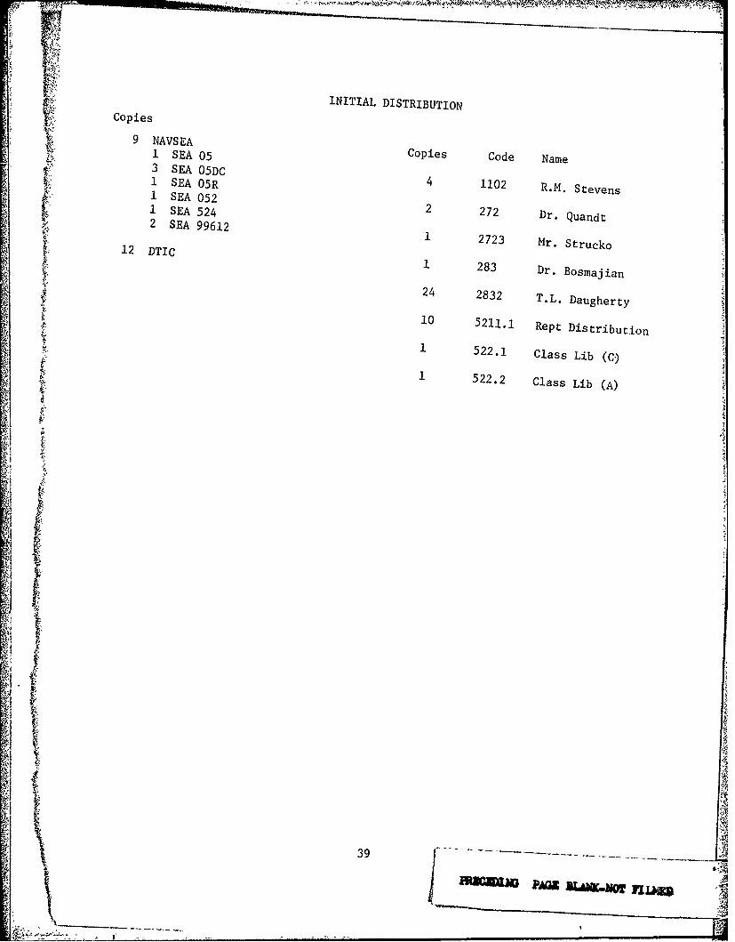
r INITIAL DISTRIBUTION
Copies
9 NAVSEA Copies Coe Nm1 SEA05 Cd
3 SEA 05RC 4 1102 R.M. Stevens1 SEAO052
1 SEA 524 2 272 Dr. Quandt1 SEA592
2VE 91 1 2723 Mr. Strucko12 DTIC 1283 Dr- Bosmajian
24 2832 T.L. Daugherty
10 511,1 Rept Distribution
10 5221 l as ix1 522.2 Class Lib (CA)
132.9CasLi A
JPG
............. ....................
I!A

DISCLAIMER NOTICE
THIS DOCUMENT IS BEST QUALITYPRACTICABLE. THE COPY FURNISHEDTO DTIC CONTAINED A SIGNIFICANTNUMBER OF PAGES WHICH DO NOTREPRODUCE LEGIBLY.
Recommended


![Thrust Bearing Using PVDF Sensors - Semantic Scholar tilted pad thrust bearing, developed by Michell and Kingsbury [1] more than 100 years ago, in its simplest form is comprised of](https://img.pdfslide.us/doc/110x75/5b02d1fe7f8b9a2e228b75b5/thrust-bearing-using-pvdf-sensors-semantic-scholar-tilted-pad-thrust-bearing.jpg)