FORMLABS APPLICATION GUIDE:
3D Printing Splints with the Form 2
October 2017 | formlabs.com
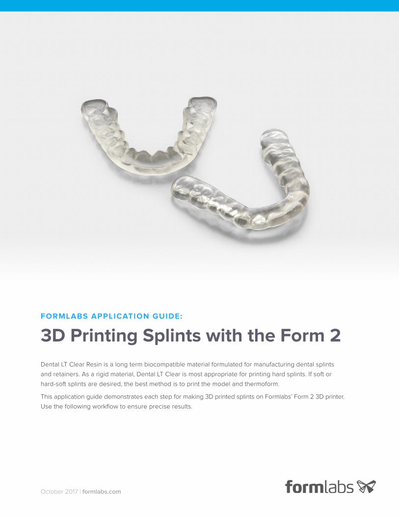
Dental LT Clear Resin is a long term biocompatible material formulated for manufacturing dental splints
and retainers. As a rigid material, Dental LT Clear is most appropriate for printing hard splints. If soft or
hard-soft splints are desired, the best method is to print the model and thermoform.
This application guide demonstrates each step for making 3D printed splints on Formlabs’ Form 2 3D printer.
Use the following workflow to ensure precise results.
FORMLABS APPLICATION GUIDE: 3D Printing Splints with the Form 2 2
Table of Contents
Scan . . . . . . . . . . . . . . . . . . . . . . . . . . . . 3
Design . . . . . . . . . . . . . . . . . . . . . . . . . . . 3
Print. . . . . . . . . . . . . . . . . . . . . . . . . . . . . 6
Prepare . . . . . . . . . . . . . . . . . . . . . . . . . . 7
Resin Tank Maintenance . . . . . . . . . . . . . . . . . 9
Made by Formlabs
Form 2 (SLA) 3D Printer
Dental LT Clear Resin
PreForm Software (free)
Finish Kit or Form Wash
Form Cure
Made by 3rd Parties
Dental Design Software (CAD)
Intraoral or Desktop Optical Scanner
Alternative Post-Cure Chamber
Ultrasonic Bath
Essentials
FORMLABS APPLICATION GUIDE: 3D Printing Splints with the Form 2 3
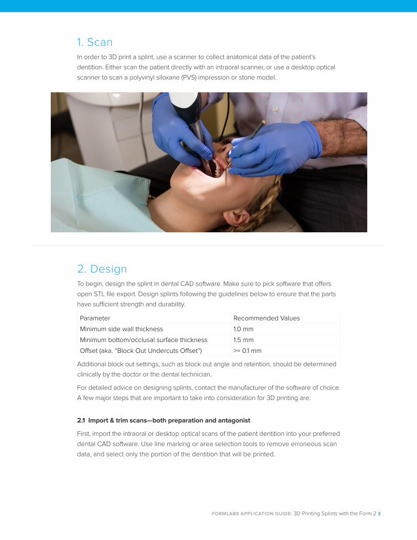
1. ScanIn order to 3D print a splint, use a scanner to collect anatomical data of the patient’s
dentition. Either scan the patient directly with an intraoral scanner, or use a desktop optical
scanner to scan a polyvinyl siloxane (PVS) impression or stone model.
2. Design To begin, design the splint in dental CAD software. Make sure to pick software that offers
open STL file export. Design splints following the guidelines below to ensure that the parts
have sufficient strength and durability.
Parameter Recommended Values
Minimum side wall thickness 1.0 mm
Minimum bottom/occlusal surface thickness 1.5 mm
Offset (aka. “Block Out Undercuts Offset”) >= 0.1 mm
Additional block out settings, such as block out angle and retention, should be determined
clinically by the doctor or the dental technician.
For detailed advice on designing splints, contact the manufacturer of the software of choice.
A few major steps that are important to take into consideration for 3D printing are:
2.1 Import & trim scans—both preparation and antagonist
First, import the intraoral or desktop optical scans of the patient dentition into your preferred
dental CAD software. Use line marking or area selection tools to remove erroneous scan
data, and select only the portion of the dentition that will be printed.
FORMLABS APPLICATION GUIDE: 3D Printing Splints with the Form 2 4
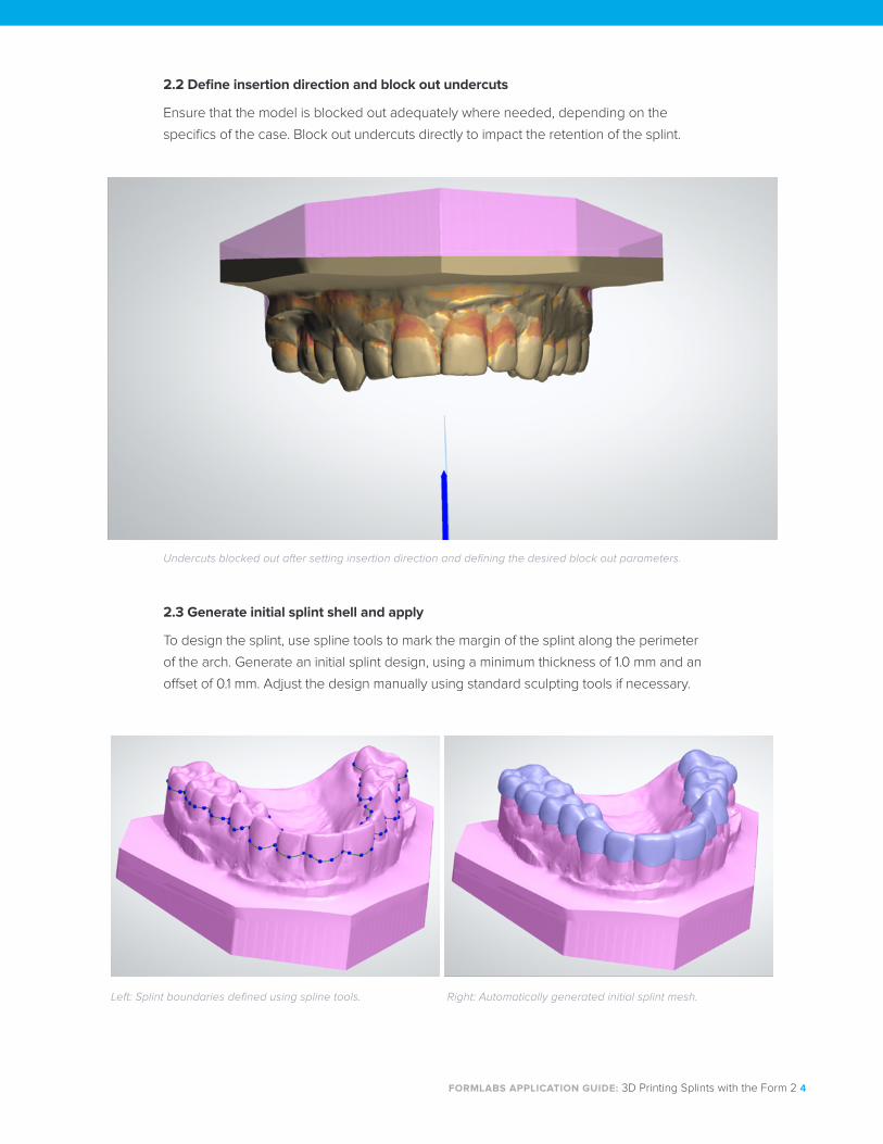
2.2 Define insertion direction and block out undercuts
Ensure that the model is blocked out adequately where needed, depending on the
specifics of the case. Block out undercuts directly to impact the retention of the splint.
2.3 Generate initial splint shell and apply
To design the splint, use spline tools to mark the margin of the splint along the perimeter
of the arch. Generate an initial splint design, using a minimum thickness of 1.0 mm and an
offset of 0.1 mm. Adjust the design manually using standard sculpting tools if necessary.
Undercuts blocked out after setting insertion direction and defining the desired block out parameters.
Left: Splint boundaries defined using spline tools. Right: Automatically generated initial splint mesh.
FORMLABS APPLICATION GUIDE: 3D Printing Splints with the Form 2 5
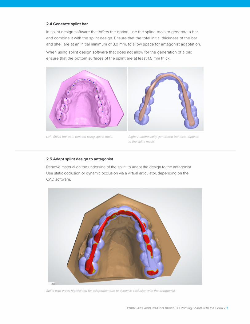
2.4 Generate splint bar
In splint design software that offers the option, use the spline tools to generate a bar
and combine it with the splint design. Ensure that the total initial thickness of the bar
and shell are at an initial minimum of 3.0 mm, to allow space for antagonist adaptation.
When using splint design software that does not allow for the generation of a bar,
ensure that the bottom surfaces of the splint are at least 1.5 mm thick.
2.5 Adapt splint design to antagonist
Remove material on the underside of the splint to adapt the design to the antagonist.
Use static occlusion or dynamic occlusion via a virtual articulator, depending on the
CAD software.
Left: Splint bar path defined using spline tools. Right: Automatically generated bar mesh applied
to the splint mesh.
Splint with areas highlighted for adaptation due to dynamic occlusion with the antagonist.
FORMLABS APPLICATION GUIDE: 3D Printing Splints with the Form 2 6
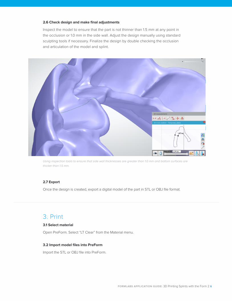
2.6 Check design and make final adjustments
Inspect the model to ensure that the part is not thinner than 1.5 mm at any point in
the occlusion or 1.0 mm in the side wall. Adjust the design manually using standard
sculpting tools if necessary. Finalize the design by double checking the occlusion
and articulation of the model and splint.
2.7 Export
Once the design is created, export a digital model of the part in STL or OBJ file format.
Using inspection tools to ensure that side wall thicknesses are greater than 1.0 mm and bottom surfaces are
thicker than 1.5 mm.
3. Print 3.1 Select material
Open PreForm. Select “LT Clear” from the Material menu.
3.2 Import model files into PreForm
Import the STL or OBJ file into PreForm.
FORMLABS APPLICATION GUIDE: 3D Printing Splints with the Form 2 7
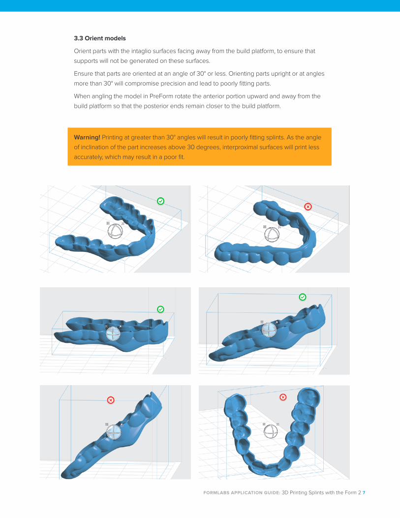
Warning! Printing at greater than 30° angles will result in poorly fitting splints. As the angle
of inclination of the part increases above 30 degrees, interproximal surfaces will print less
accurately, which may result in a poor fit.
3.3 Orient models
Orient parts with the intaglio surfaces facing away from the build platform, to ensure that
supports will not be generated on these surfaces.
Ensure that parts are oriented at an angle of 30° or less. Orienting parts upright or at angles
more than 30° will compromise precision and lead to poorly fitting parts.
When angling the model in PreForm rotate the anterior portion upward and away from the
build platform so that the posterior ends remain closer to the build platform.
FORMLABS APPLICATION GUIDE: 3D Printing Splints with the Form 2 8
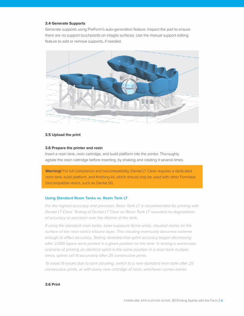
3.4 Generate Supports
Generate supports using PreForm’s auto-generation feature. Inspect the part to ensure
there are no support touchpoints on intaglio surfaces. Use the manual support editing
feature to add or remove supports, if needed.
3.5 Upload the print
3.6 Prepare the printer and resin
Insert a resin tank, resin cartridge, and build platform into the printer. Thoroughly
agitate the resin cartridge before inserting, by shaking and rotating it several times.
Warning! For full compliance and biocompatibility, Dental LT Clear requires a dedicated
resin tank, build platform, and finishing kit, which should only be used with other Formlabs
biocompatible resins, such as Dental SG.
Using Standard Resin Tanks vs. Resin Tank LT
For the highest accuracy and precision, Resin Tank LT is recommended for printing with
Dental LT Clear. Testing of Dental LT Clear on Resin Tank LT revealed no degradation
of accuracy or precision over the lifetime of the tank.
If using the standard resin tanks, laser exposure forms white, clouded marks on the
surface of the resin tank’s silicone layer. This clouding eventually becomes extreme
enough to affect accuracy. Testing revealed that splint accuracy began decreasing
after 2,000 layers were printed in a given position on the tank. In testing a worst-case
scenario of printing an identical splint in the same position in a resin tank multiple
times, splints still fit accurately after 25 consecutive prints.
To avoid fit issues due to tank clouding, switch to a new standard resin tank after 25
consecutive prints, or with every new cartridge of resin, whichever comes earlier.
3.6 Print
FORMLABS APPLICATION GUIDE: 3D Printing Splints with the Form 2 9
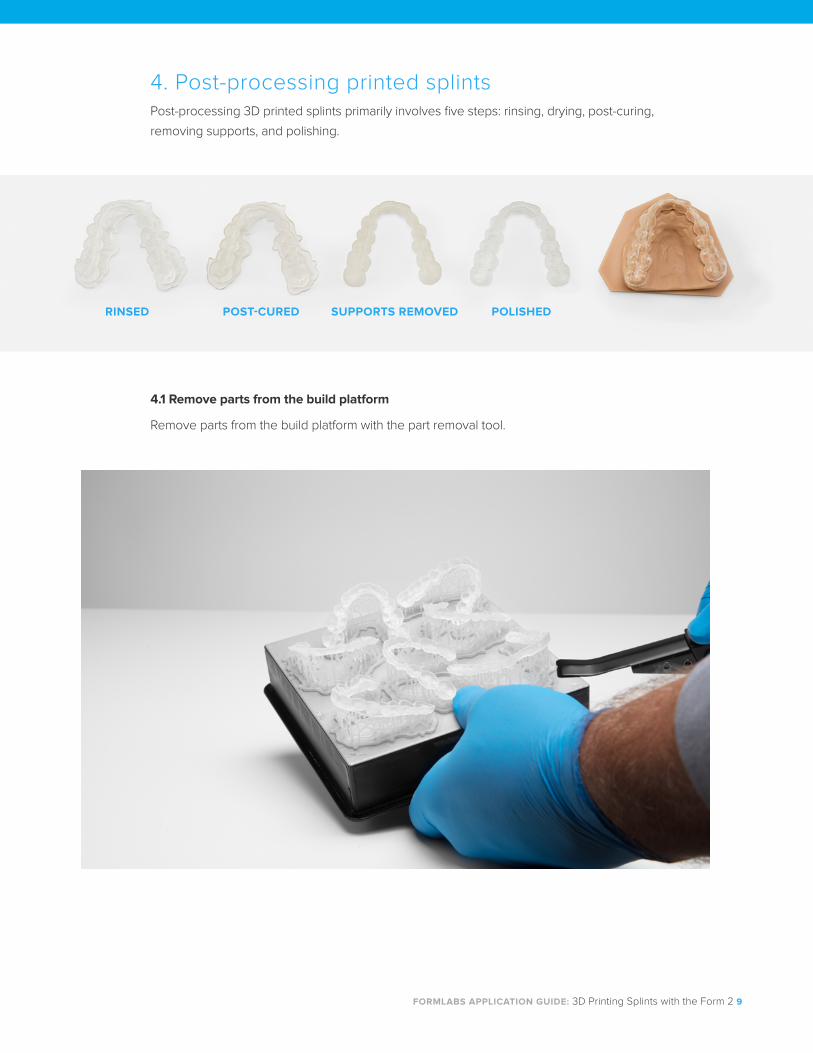
4. Post-processing printed splints Post-processing 3D printed splints primarily involves five steps: rinsing, drying, post-curing,
removing supports, and polishing.
4.1 Remove parts from the build platform
Remove parts from the build platform with the part removal tool.
RINSED POST-CURED SUPPORTS REMOVED POLISHED
FORMLABS APPLICATION GUIDE: 3D Printing Splints with the Form 2 10
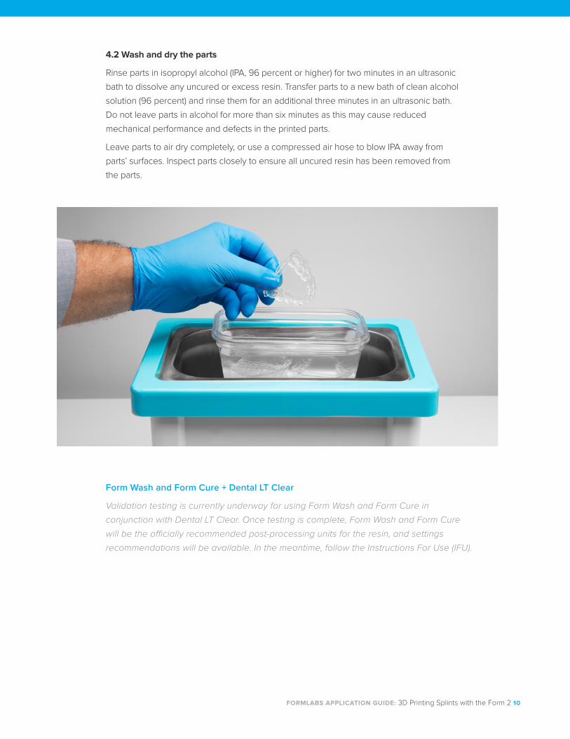
4.2 Wash and dry the parts
Rinse parts in isopropyl alcohol (IPA, 96 percent or higher) for two minutes in an ultrasonic
bath to dissolve any uncured or excess resin. Transfer parts to a new bath of clean alcohol
solution (96 percent) and rinse them for an additional three minutes in an ultrasonic bath.
Do not leave parts in alcohol for more than six minutes as this may cause reduced
mechanical performance and defects in the printed parts.
Leave parts to air dry completely, or use a compressed air hose to blow IPA away from
parts’ surfaces. Inspect parts closely to ensure all uncured resin has been removed from
the parts.
Form Wash and Form Cure + Dental LT Clear
Validation testing is currently underway for using Form Wash and Form Cure in
conjunction with Dental LT Clear. Once testing is complete, Form Wash and Form Cure
will be the officially recommended post-processing units for the resin, and settings
recommendations will be available. In the meantime, follow the Instructions For Use (IFU).
FORMLABS APPLICATION GUIDE: 3D Printing Splints with the Form 2 11
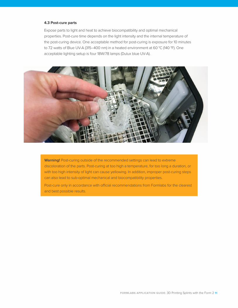
4.3 Post-cure parts
Expose parts to light and heat to achieve biocompatibility and optimal mechanical
properties. Post-cure time depends on the light intensity and the internal temperature of
the post-curing device. One acceptable method for post-curing is exposure for 10 minutes
to 72 watts of Blue UV-A (315–400 nm) in a heated environment at 60 °C (140 °F). One
acceptable lighting setup is four 18W/78 lamps (Dulux blue UV-A).
Warning! Post-curing outside of the recommended settings can lead to extreme
discoloration of the parts. Post-curing at too high a temperature, for too long a duration, or
with too high intensity of light can cause yellowing. In addition, improper post-curing steps
can also lead to sub-optimal mechanical and biocompatibility properties.
Post-cure only in accordance with official recommendations from Formlabs for the clearest
and best possible results.
FORMLABS APPLICATION GUIDE: 3D Printing Splints with the Form 2 12
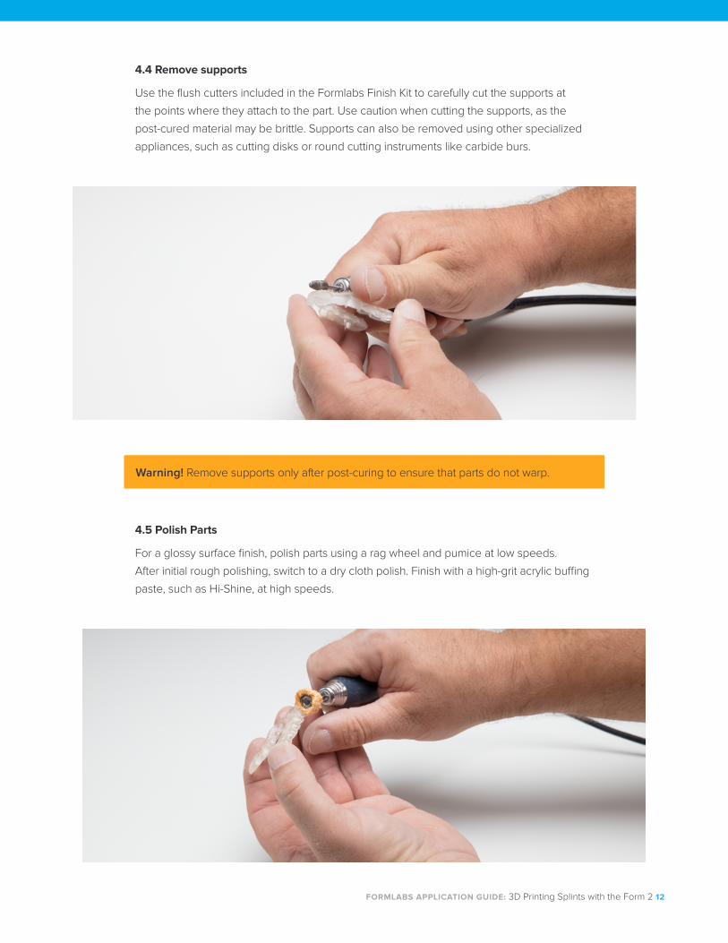
4.4 Remove supports
Use the flush cutters included in the Formlabs Finish Kit to carefully cut the supports at
the points where they attach to the part. Use caution when cutting the supports, as the
post-cured material may be brittle. Supports can also be removed using other specialized
appliances, such as cutting disks or round cutting instruments like carbide burs.
4.5 Polish Parts
For a glossy surface finish, polish parts using a rag wheel and pumice at low speeds.
After initial rough polishing, switch to a dry cloth polish. Finish with a high-grit acrylic buffing
paste, such as Hi-Shine, at high speeds.
Warning! Remove supports only after post-curing to ensure that parts do not warp.
FORMLABS APPLICATION GUIDE: 3D Printing Splints with the Form 2 13
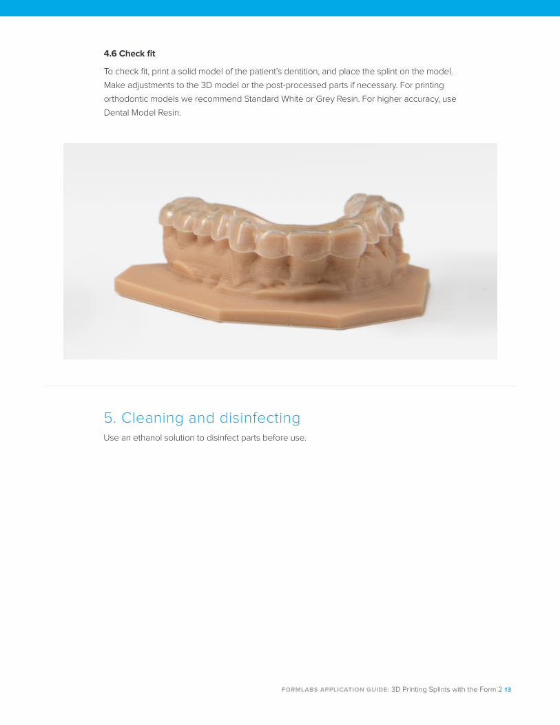
4.6 Check fit
To check fit, print a solid model of the patient’s dentition, and place the splint on the model.
Make adjustments to the 3D model or the post-processed parts if necessary. For printing
orthodontic models we recommend Standard White or Grey Resin. For higher accuracy, use
Dental Model Resin.
5. Cleaning and disinfectingUse an ethanol solution to disinfect parts before use.
FORMLABS APPLICATION GUIDE: 3D Printing Splints with the Form 2 14
BiocompatibilityDental LT Clear is a Class IIa biocompatible resin that is in conformity with the essential
requirements and provisions of the Council Directive 93/42/EEC concerning medical devices
as amended by Directive 2007/47/EC, and is in conformity with the following standards:
EN ISO 1641:2009 EN-ISO 10993-1:2009/AC:2010
EN-ISO 10993-3:2009 EN-ISO 10993-5:2009
EN 908:2008 EC Declaration of Conformity
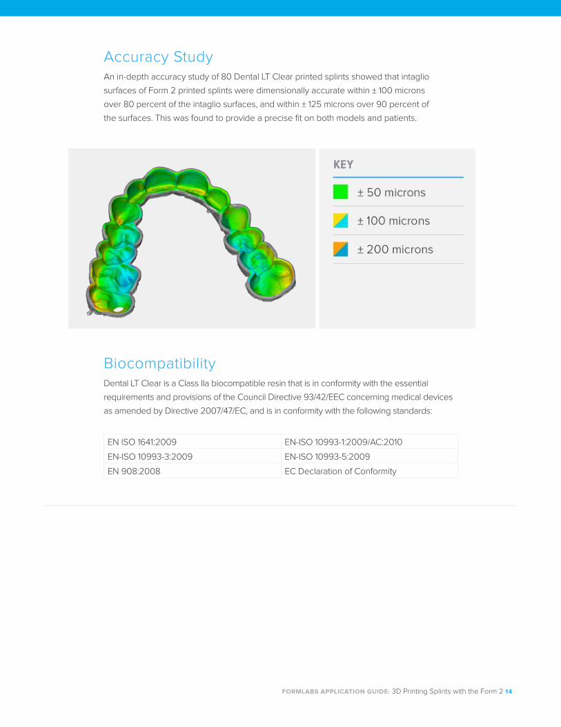
Accuracy StudyAn in-depth accuracy study of 80 Dental LT Clear printed splints showed that intaglio
surfaces of Form 2 printed splints were dimensionally accurate within ± 100 microns
over 80 percent of the intaglio surfaces, and within ± 125 microns over 90 percent of
the surfaces. This was found to provide a precise fit on both models and patients.
Recommended