FORCE MAIN EXTENSION
DIVISION 9
FINISHES
IWSD 01/2011 09900-1 Painting and Coating
AECOM REBID
SECTION 09900
PAINTING AND COATING
PART 1 – GENERAL
1.01 DESCRIPTION
A. This section includes materials and application of painting and coating systems for the
following surfaces:
1. Submerged metal.
2. Exposed metal.
3. Buried metal.
4. Concrete and masonry.
5. Metal in contact with concrete.
6. Wood and masonry.
B. It does not include coating steel water tanks and reservoirs.
1.02 SUBMITTALS
A. Submit shop drawings in accordance with the General Conditions, Section 01300 and the
following.
B. Submit manufacturer’s data sheets showing the following information:
1. Percent solids by volume.
2. Minimum and maximum recommended dry-film thickness per coat for prime,
intermediate, and finish coats.
3. Recommended surface preparation.
4. Recommended thinners.
5. Statement verifying that the specified prime coat is recommended by the
manufacturer for use with the specified intermediate and finish coats.
6. Application instructions including recommended equipment and temperature
limitations.
7. Curing requirements and instructions.
C. Submit color swatches.
IWSD 01/2011 09900-2 Painting and Coating
AECOM REBID
D. Submit certificate identifying the type and gradation of abrasives used for surface
preparation.
E. Submit material safety data sheets for each coating.
PART 2 – MATERIALS
2.01 PAINTING AND COATING SYSTEMS
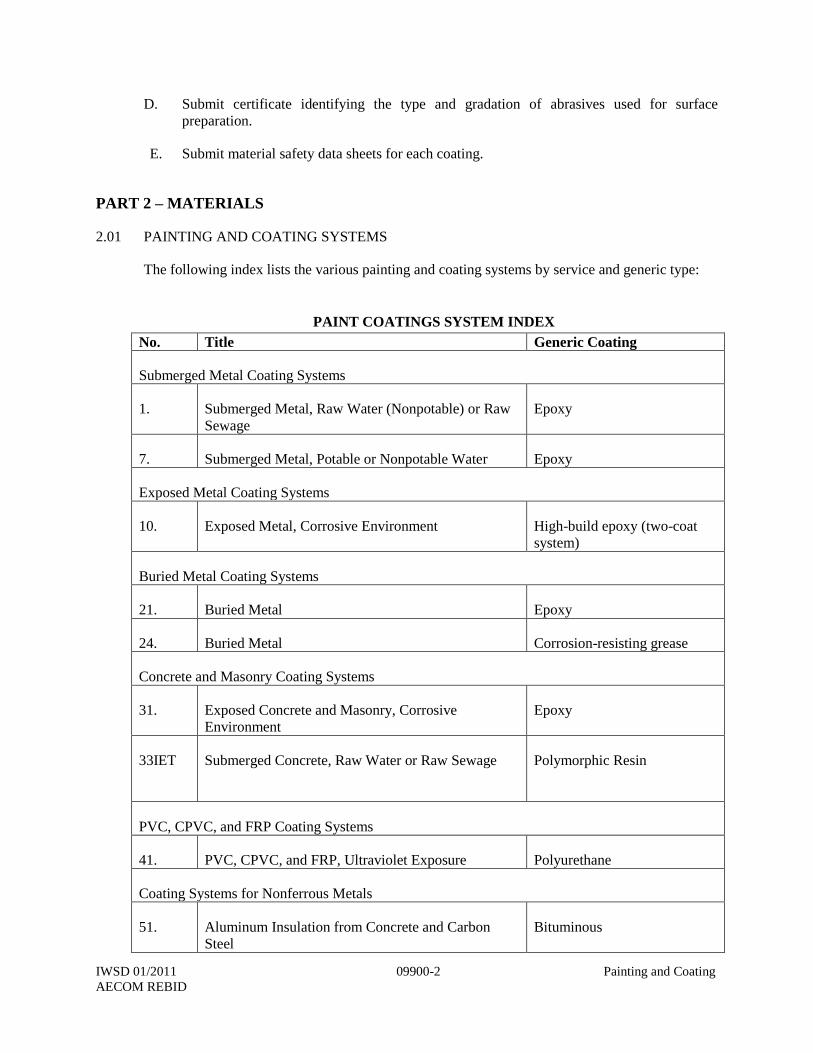
The following index lists the various painting and coating systems by service and generic type:
PAINT COATINGS SYSTEM INDEX
No. Title Generic Coating
Submerged Metal Coating Systems
1. Submerged Metal, Raw Water (Nonpotable) or Raw
Sewage
Epoxy
7. Submerged Metal, Potable or Nonpotable Water Epoxy
Exposed Metal Coating Systems
10. Exposed Metal, Corrosive Environment High-build epoxy (two-coat
system)
Buried Metal Coating Systems
21. Buried Metal Epoxy
24. Buried Metal Corrosion-resisting grease
Concrete and Masonry Coating Systems
31. Exposed Concrete and Masonry, Corrosive
Environment
Epoxy
33IET Submerged Concrete, Raw Water or Raw Sewage
Polymorphic Resin
PVC, CPVC, and FRP Coating Systems
41. PVC, CPVC, and FRP, Ultraviolet Exposure Polyurethane
Coating Systems for Nonferrous Metals
51. Aluminum Insulation from Concrete and Carbon
Steel
Bituminous
IWSD 01/2011 09900-3 Painting and Coating
AECOM REBID
These systems are specified in detail in the following paragraphs. For each coating, the
required surface preparation, prime coat, intermediate coat (if required), topcoat, and
coating thicknesses are described. Mil thicknesses shown are minimum dry-film
thicknesses.
2.02 SUBMERGED METAL COATING SYSTEMS
A. System No. 1--Submerged Metal—Raw Water (Nonpotable) or Raw Sewage:
Type: Epoxy having a minimum volume solids of 80%.
Service Conditions: For use with metal pipes or structures (such as scum troughs, sluice
gates, or piping) alternately submerged in raw sewage or raw water (nonpotable) and
exposed to a moist saturated hydrogen sulfide atmosphere, as in raw sewage wet wells.
Minimum temperature resistance of the coating shall be 140°F for moist heat conditions.
Surface Preparation: SSPC SP-10.
Prime Coat: ICI Devoe Bar-Rust 233H, 8 mils; Tnemec 104-1211, 8 mils; or equal.
Finish Coat: ICI Devoe Bar-Rust 233H, 8 mils; Tnemec 104-ABO5, 8 mils; or equal.
B. System No. 7--Submerged Metal, Potable or Nonpotable Water:
Type: Epoxy.
Service Conditions: For use with structures, valves, piping, or equipment immersed in
potable or nonpotable water.
Surface Preparation: SSPC SP-10.
Coating System: Apply the manufacturer’s recommended number of coats to attain the
specified minimum coating thickness. Products: Devoe Bar-Rust 233H OR Tnemec 100
C. Exposed Metal Coating Systems
System No. 10--Exposed Metal, Corrosive Environment:
Type: High-build epoxy intermediate coat having a minimum volume solids of 60%, with
an inorganic zinc prime coat and a pigmented polyurethane finish coat having a minimum
volume solids of 52%.
Service Conditions: For use with metal structures or pipes subjected to water
condensation; chemical fumes, such as hydrogen sulfide; salt spray; and chemical
contact.
Surface Preparation: SSPC SP-10.
Prime Coat: Self-curing, two-component inorganic zinc-rich coating recommended by the
manufacturer for overcoating with a high-build epoxy finish coat. Minimum zinc content
shall be 12 pounds per gallon. Apply to a thickness of 3 mils. Products: Tnemec 90-96,
IWSD 01/2011 09900-4 Painting and Coating
AECOM REBID
Devoe Catha-Coat 304 or 304V, International Interzinc 180HS, Ameron Dimetcote 9 or
21-9, Engard 519, Carboline 11 HS, or equal.
Intermediate Coat: Tnemec 104, ICI Devoe Devran 224 HS, International Interguard
760HS, Ameron 385, Engard 460 HS, Carboline 888 or 890, or equal; 5 mils.
Finish Coat: Two-component pigmented acrylic or aliphatic polyurethane recommended
by the manufacturer for overcoating a high-build epoxy coating. Apply to a thickness of
at least 2 mils. Products: Tnemec Series 1074, ICI Devoe Devthane 379, International
Interline 990HS, Ameron 450 HS, Engard 428 HS, Carboline 134 HG, or equal.
D. Buried Metal Coating Systems
System No. 21--Buried Metal:
Type: High solids epoxy or phenolic epoxy having a minimum volume solids of 80%
(ASTM D 2697).
Service Conditions: Buried metal, such as valves, flanges, bolts, nuts, structural steel, and
fittings.
Surface Preparation: SSPC SP-10.
Coating System: Apply three or more coats of Ameron 400, Tnemec 104 HS, Engard 480
HS, ICI Devoe Bar-Rust 233H, Carboline 890LT, or equal; 30 mils total. Maximum
thickness of an individual coating shall not exceed the manufacturer’s recommendation.
System No. 24--Buried Metal:
Type: Corrosion-resisting grease.
Service Conditions: Buried metal, such as bolts, bolt threads, tie rods, and nuts.
Surface Preparation: SSPC SP-3 or SP-6.
Coating: NO-OX-ID GG-2 as manufactured by Sanchem, Inc. Apply to a minimum
thickness of 1/4 inch.
E. Concrete and Masonry Coating Systems
System No. 31--Exposed Concrete and Masonry, Corrosive Environment:
Type: Polyamide cured epoxy having a minimum volume solids of 53%.
Service Conditions: Concrete and masonry exposed to corrosive atmospheres, such as
hydrogen sulfide gas, chlorine gas, or chlorinated effluent sprays in wastewater treatment
plants.
Surface Preparation: In accordance with Part 3.D.
Prime Coat: Epoxy filler compound or epoxy masonry filler having a minimum solids
volume of 60%. Apply one coat to fill voids, pores, and cracks. Products: Tnemec 54-
IWSD 01/2011 09900-5 Painting and Coating
AECOM REBID
660, International Intercryl 320WB, Amerlock 400 BF, ICI Devoe Devran 265 BHF,
Sentry 610, or equal.
Intermediate Coat: One coat of Carboline Bitumastic 300M, Tnemec N69-1211,
International Interguard 760HS, Amerlock 400, ICI Devoe Bar-Rust 233 H, Carboline
890, or equal. Apply to a minimum dry-film thickness of 6 mils (10 mils for Bitumastic
300M).
Finish Coat: Two coats of Carboline Bitumastic 300M, Tnemec N69, International
Interguard 760HS, Amerlock 400, ICI Devoe Bar-Rust 233 H, Carboline 890, or equal.
Apply to a minimum dry-film thickness of 6 mils per coat (10 mils for Bitumastic 300M).
System No. 33IET--Submerged Concrete, Raw Sewage or Raw Water:
Type: Rapid curing, non-shrinking, 100% solids, two components, modified Isophthalic
Polyester Resin.
Service Conditions: Concrete submerged in raw water or raw sewage and structures
containing moist hydrogen sulfide such as manholes and sewage pumping station wet
wells.
Surface Preparation: In accordance with Part 3.D. and the manufacturer’s instruction on
surface preparation.
Prime Coat: DS-101, manufactured by IET Systems, shall be applied at the rate of 5 to 10
mils per square foot and properly catalyzed. All cracks, spalls, holes, etc., shall be filled
by applying DS-201 Crack & Spall Repair Grout.
Intermediate Coat: DS-301, manufactured by IET Systems, shall be applied over the
gelled DS-101 and DS-201. Thoroughly mix 1 weight IET SYSTEMS Polymorphic
Resin with 2 weights 30 or 60 mesh silica sand, 1 weight silica flour, with thixotropy as
needed. Intermediate Coat shall be applied in successive 30 mils passes to a thickness
that if combined with the thickness of prime coat and finish coat will be equal or greater
than the minimum specified coating thickness. Each successive pass shall be tinted whiter
than the preceding pass to assured complete coverage.
Finish Coats: DS-401, manufactured by IET Systems, shall be applied over the gelled
DS-301. The DS-401 shall consist a minimum thickness of 5 to 10 mils of IET Systems
Polymorphic Resin.
Total minimum applied coating thickness will be 125 mils for new structures and 250
mils for rehabilitated structures.
F. PVC, CPVC, and FRP Coating System
System No. 41--PVC, CPVC, and FRP, Ultraviolet Exposure or Color Coding:
Type: Epoxy primer with a minimum volume solids of 54% and a pigmented
polyurethane enamel having a minimum volume solids of 52%.
Service Conditions: Color coding of PVC or CPVC or FRP exposed to sunlight.
IWSD 01/2011 09900-6 Painting and Coating
AECOM REBID
Surface Preparation: SSPC SP-1. Then lightly abrade the surface with medium-grain
sandpaper.
Prime Coat: One coat of Tnemec Series N69 Epoxoline, International 7510, Ameron 385,
ICI Devoe Devran 224 HS, Sherwin-Williams Macropoxy 646 B58 series, Carboline 888
or 890, PPG PITT-GUARD® Direct-to-Rust Epoxy Mastic Coating 97-145 Series, or
equal. Apply to a minimum dry-film thickness of 4 mils.
Finish Coat: One coat of Tnemec Series 1075, International Interthane 990HS, Ameron
450 HS, ICI Devoe Devran 379, Carboline 134 HG, Sherwin-Williams Hi-Solids
Polyurethane B65-300 series, PPG PITTHANE® Ultra Gloss Urethane Enamel 95-812
Series, or equal. Apply to a minimum dry-film thickness of 3 mils.
G. Coating Systems for Nonferrous Metals
System No. 51--Aluminum Insulation from Concrete and Carbon Steel:
Type: Bituminous paint having a minimum volume solids of 68% coal-tar pitch based.
Service Conditions: Coat areas of aluminum grating, stairs, structural members or
aluminum fabrications, in contact with concrete or carbon steel with this system.
Surface Preparation: Solvent or steam cleaning per SSPC SP-1; do not use alkali
cleaning. Then dust blast.
Prime Coat: Apply synthetic resin or epoxy primer to metal surface before finish coats.
Products: International Intervinux VTA528/529, or equal. No primer required for
Carboline or Tnemec.
Finish Coat: Carboline Super Service Black, Tnemec 46-465, International Intertuf 100,
or equal. Apply two coats to a minimum dry-film thickness of 12 mils each.
H. Abrasives for Surface Preparation
1. Abrasives used for preparation of ferrous (excluding stainless steel) surfaces shall
be one of the following:
a. 16 to 30 or 16 to 40 mesh silica sand or mineral grit.
b. 20 to 40 mesh garnet.
c. Crushed iron slag, 100% retained on No. 80 mesh.
d. SAE Grade G-40 or G-50 iron or steel grit.
2. Abrasives used for preparation of concrete and masonry surfaces shall be 16 to 30
or 16 to 40 mesh silica sand.
3. In the above gradations, 100% of the material shall pass through the first stated
sieve size and 100% shall be retained on the second stated sieve size.
IWSD 01/2011 09900-7 Painting and Coating
AECOM REBID
PART 3 – EXECUTION
3.01 WEATHER CONDITIONS
A. Do not paint in the rain, wind, snow, mist, and fog or when steel or metal surface
temperatures are less than 5°F above the dew point.
B. Do not apply paint when the relative humidity is above 85%. For Systems Nos. 3 and 14,
the relative humidity shall not exceed 95%.
C. Do not paint when temperature of metal to be painted is above 120°F.
D. Do not apply alkyd, inorganic zinc, silicone aluminum, or silicone acrylic paints if air or
surface temperature is below 40°F or expected to be below 40°F within 24 hours.
E. Do not apply epoxy, acrylic latex, and polyurethane paints on an exterior or interior
surface if air or surface temperature is below 60°F or expected to drop below 60°F in 24
hours.
3.02 SURFACE PREPARATION PROCEDURES
A. Remove oil and grease from metal surfaces in accordance with SSPC SP-1. Use clean
cloths and cleaning solvents and wipe dry with clean cloths. Do not leave a film or greasy
residue on the cleaned surfaces before abrasive blasting.
B. Remove weld spatter and weld slag from metal surfaces and grind smoothly rough welds,
beads, peaked corners, and sharp edges including erection lugs in accordance with SSPC
SP-2 and SSPC SP-3. Grind 0.020 inch (minimum) off the weld caps on pipe weld seams.
Grind outside sharp corners, such as the outside edges of flanges, to a minimum radius of
1/4 inch.
C. Do not abrasive blast or prepare more surface area in one day than can be coated in one
day; prepare surfaces and apply coatings the same day. Remove sharp edges, burrs, and
weld spatter.
D. Do not abrasive blast epoxy- or enamel-coated pipe that has already been factory coated,
except to repair scratched or damaged coatings.
E. For carbon steel, do not touch the surface between the time of abrasive blasting and the
time the coating is applied. Apply coatings within two hours of blasting or before any rust
bloom forms.
F. Surface preparation shall conform with the SSPC specifications as follows:
IWSD 01/2011 09900-8 Painting and Coating
AECOM REBID
Solvent Cleaning SP-1
Hand Tool Cleaning SP-2
Power Tool Cleaning SP-3
White Metal Blast Cleaning SP-5
Commercial Blast Cleaning SP-6
Brush-Off Blast Cleaning SP-7
Pickling SP-8
Near-White Blast Cleaning SP-10
Power Tool Cleaning to Bare Metal SP-11
Surface Preparation and Cleaning of Steel and Other Hard
Materials by High- and Ultrahigh-Pressure Water Jetting
Prior to Recoating
SP-12
Surface Preparation of Concrete SP-13
G. Wherever the words “solvent cleaning,” “hand tool cleaning,” “wire brushing,” or “blast
cleaning” or similar words are used in these specifications or in paint manufacturer’s
specifications, they shall be understood to refer to the applicable SSPC (Steel Structure
Painting Council), surface preparation specifications listed above.
H. Brush-off blasting of concrete and masonry surfaces is defined as opening subsurface
holes and voids and etching the surface for a coating to bond.
I. For carbon steel surfaces, after abrasive blast cleaning, the height of the surface profile
shall be 2 to 3 mils. If this cannot be achieved with the surface preparation named in the
painting system, SSPC SP-5 may be required. Verify the surface profile by measuring
with an impresser tape acceptable to the Owner’s Representative. Perform a minimum of
one test per 100 square feet of surface area. Testing shall be witnessed by the Owner’s
Representative. The impresser tape used in the test shall be permanently marked with
the date, time, and locations where the test was made. Test results shall be promptly
presented to the Owner’s Representative.
J. Do not apply any part of a coating system before the Owner’s Representative has
reviewed the surface preparation. If coating has been applied without this review, if
directed by the Owner’s Representative, remove the applied coating by abrasive blasting
and reapply the coat in accordance with this specification.
3.03 ABRASIVE BLAST CLEANING
A. Use dry abrasive blast cleaning for metal surfaces. Do not use abrasives in automatic
equipment that have become contaminated. When shop or field blast cleaning with
handheld nozzles, do not recycle or reuse blast particles.
B. After blast cleaning and prior to application of coating, dry clean surfaces to be coated by
dusting, sweeping, and vacuuming to remove residue from blasting. Apply the specified
primer or touch-up coating within the period of an eight-hour working day. Do not apply
IWSD 01/2011 09900-9 Painting and Coating
AECOM REBID
coating over damp or moist surfaces. Reclean prior to application of primer or touch-up
coating any blast cleaned surface not coated within said eight-hour period.
C. Keep the area of the work in a clean condition and do not permit blasting particles to
accumulate and constitute a nuisance or hazard.
D. During sandblast cleaning, prevent damage to adjacent coatings. Schedule blast cleaning
and coating such that dust, dirt, blast particles, old coatings, rust, mill scale, etc., will not
damage or fall upon wet or newly coated surfaces.
3.04 PREPARATION OF CONCRETE AND MASONRY SURFACES TO BE COATED
A. Surface preparation of concrete and masonry surfaces shall be in accordance with SSPC
SP-13 and the following.
B. Do not apply coating until concrete has cured at least 30 days. Finish concrete surfaces
per Section 030500. Do not use curing compound on surfaces that are to be coated.
C. Concrete and masonry surfaces on which coatings are to be applied shall be of even
color, gray or gray-white. The surface shall have no pits, pockets, holes, or sharp changes
of surface elevation. Scrubbing with a stiff-bristle fiber brush shall produce no dusting or
dislodging of cement or sand. Sprinkling water on the surface shall produce no water
beads or standing droplets. Concrete and masonry shall be free of laitance and slick
surfaces.
D. Detergent clean the concrete or masonry surface with trisodium phosphate per ASTM D
4258. Then sandblast surfaces (brush-off blast). Floor slabs may be acid etched per
ASTM D 4260 in lieu of sandblasting. After sandblasting, wash surfaces with water to
remove dust and salts, per ASTM D 4258 or D 4261. The grain of the concrete surface to
touch shall not be rougher than that of No. 10 mesh sand.
E. Prior to coating concrete, plaster, and masonry with System No. 31, 33, or 34, determine
the presence of capillary moisture per ASTM D 4263, except as modified below. Tape a
4-foot by 4-foot sheet of polyethylene plastic to the concrete surface to be coated. Allow
the plastic sheet to remain in place at least 24 hours. After the specified time has elapsed,
remove the plastic sheet and visually examine both the underside of the plastic sheet and
the concrete surface beneath it. There shall be no indication of moisture on either surface.
If moisture is indicated, allow additional curing time for the concrete and then retest.
Provide one test sheet for every 500 square feet of concrete surface to be coated. For
walls, provide one test sheet for each 10 feet (or fraction thereof) of vertical rise in all
elevations starting within 12 inches of the floor or base slab.
F. Acceptance criteria for concrete surfaces shall be in accordance with SSPC SP-13, Table
1, “Severe Service.”
G. Do not apply coatings to concrete when the concrete is outgassing. Apply coatings only
when the concrete surface temperature is stable, not rising.
IWSD 01/2011 09900-10 Painting and
Coating
AECOM REBID
3.05 PROCEDURES FOR ITEMS HAVING SHOP-APPLIED PRIME COATS
A. After application of primer to surfaces, allow coating to cure for a minimum of two hours
before handling to minimize damage.
B. When loading for shipment to the project site, use spacers and other protective devices to
separate items to prevent damaging the shop-primed surfaces during transit and
unloading. If wood spacers are used, remove wood splinters and particles from the shop-
primed surfaces after separation. Use padded chains or ribbon binders to secure the
loaded items and minimize damage to the shop-primed surfaces.
1. Cover shop-primed items 100% with protective coverings or tarpaulins to prevent
deposition of road salts, fuel residue, and other contaminants in transit.
2. Handle shop-primed items with care during unloading, installation, and erection
operations to minimize damage. Do not place or store shop-primed items on the
ground or on top of other work unless ground or work is covered with a protective
covering or tarpaulin. Place shop-primed items above the ground upon platforms,
skids, or other supports.
C. Field Touch-Up of Shop-Applied Prime Coats
1. Remove oil and grease surface contaminants on metal surfaces in accordance with
SSPC SP-1. Use clean rags wetted with a degreasing solution, rinse with clean water,
and wipe dry.
2. Remove dust, dirt, salts, moisture, chalking primers, or other surface contaminants
that will affect the adhesion or durability of the coating system. Use a high-pressure
water blaster or scrub surfaces with a broom or brush wetted with a solution of
trisodium phosphate, detergent, and water. Before applying intermediate or finish
coats to inorganic zinc primers, remove any soluble zinc salts that have formed by
means of scrubbing with a stiff bristle brush. Rinse scrubbed surfaces with clean
water.
3. Remove loose or peeling primer and other surface contaminants not easily removed
by the previous cleaning methods in accordance with SSPC SP-7. Take care that
remaining primers are not damaged by the blast cleaning operation. Remaining
primers shall be firmly bonded to the steel surfaces with blast cleaned edges
feathered.
4. Remove rust, scaling, or primer damaged by welding or during shipment, storage,
and erection in accordance with SSPC SP-10. Take care that remaining primers are
not damaged by the blast cleaning operation. Areas smaller than 1 square inch may
be prepared per SSPC SP-11. Remaining primers shall be firmly bonded to the steel
surfaces with cleaned edges feathered.
5. Use repair procedures on damaged primer that protects adjacent primer. Blast
cleaning may require the use of lower air pressure, smaller nozzles, and abrasive
particle sizes, short blast nozzle distance from surface, shielding, and/or masking.
IWSD 01/2011 09900-11 Painting and
Coating
AECOM REBID
6. After abrasive blast cleaning of damaged and defective areas, remove dust, blast
particles, and other debris by dusting, sweeping, and vacuuming; then apply the
specified touch-up coating.
7. Surfaces that are shop primed with inorganic zinc primers shall receive a field touch-
up of organic zinc primer per System No. 18 to cover scratches or abraded areas.
8. Surfaces that are shop primed shall receive a field touch-up of the same primer used
in the original prime coat.
D. Painting Systems
1. Materials of a specified painting system, including primer, intermediate, and finish
coats, shall be produced by the same manufacturer. Thinners, cleaners, driers, and
other additives shall be as recommended by the paint manufacturer for the particular
coating system.
2. Deliver paints to the jobsite in the original, unopened containers.
E. Paint Storage and Mixing
1. Store and mix materials only in areas designated for that purpose by the Owner’s
Representative. The area shall be well-ventilated, with precautionary measures taken
to prevent fire hazards. Post “No Smoking” signs. Storage and mixing areas shall be
clean and free of rags, waste, and scrapings. Tightly close containers after each use.
Store paint at an ambient temperature from 50°F to 100°F.
2. Prepare multiple-component coatings using all of the contents of the container for
each component as packaged by the paint manufacturer. Do not use partial batches.
Do not use multiple-component coatings that have been mixed beyond their pot life.
Provide small quantity kits for touch-up painting and for painting other small areas.
Mix only the components specified and furnished by the paint manufacturer. Do not
intermix additional components for reasons of color or otherwise, even within the
same generic type of coating.
F. Procedures for the Application of Coatings
1. Conform to the requirements of SSPC PA-1. Follow the recommendations of the
coating manufacturer including the selection of spray equipment, brushes, rollers,
cleaners, thinners, mixing, drying time, temperature and humidity of application, and
safety precautions.
2. Stir, strain, and keep coating materials at a uniform consistency during application.
Power mix components. For multiple component materials, premix each component
before combining. Apply each coating evenly, free of brush marks, sags, runs, and
other evidence of poor workmanship. Use a different shade or tint on succeeding
coating applications to indicate coverage where possible. Finished surfaces shall be
free from defects or blemishes.
3. Do not use thinners unless recommended by the coating manufacturer. If thinning is
allowed, do not exceed the maximum allowable amount of thinner per gallon of
IWSD 01/2011 09900-12 Painting and
Coating
AECOM REBID
coating material. Stir coating materials at all times when adding thinner. Do not flood
the coating material surface with thinner prior to mixing. Do not reduce coating
materials more than is absolutely necessary to obtain the proper application
characteristics and to obtain the specified dry-film thicknesses.
4. Remove dust, blast particles, and other debris from blast cleaned surfaces by dusting,
sweeping, and vacuuming. Allow ventilator fans to clean airborne dust to provide
good visibility of working area prior to coating applications. Remove dust from
coated surfaces by dusting, sweeping, and vacuuming prior to applying succeeding
coats.
5. Apply coating systems to the specified minimum dry-film thicknesses as measured
from above the peaks of the surface profile.
6. Apply primer immediately after blast cleaning and before any surface rusting occurs,
or any dust, dirt, or any foreign matter has accumulated. Reclean surfaces by blast
cleaning that have surface colored or become moist prior to coating application.
7. Apply a brush coat of primer on welds, sharp edges, nuts, bolts, and irregular
surfaces prior to the application of the primer and finish coat. Apply the brush coat
prior to and in conjunction with the spray coat application. Apply the spray coat over
the brush coat.
8. Before applying subsequent coats, allow the primer and intermediate coats to dry for
the minimum curing time recommended by the manufacturer. In no case shall the
time between coats exceed the manufacturer’s recommendation.
9. Application procedures for System No.33EIT shall follow manufacturer’s
instructions.
10. Each coat shall cover the surface of the preceding coat completely, and there shall be
a visually perceptible difference in applied shade or tint of colors.
11. Applied coating systems shall be cured at 75°F or higher for 48 hours. If temperature
is lower than 75°F, curing time shall be in accordance with printed recommendations
of the manufacturer, unless otherwise allowed by the Owner’s Representative.
12. Assembled parts shall be disassembled sufficiently before painting or coating to
ensure complete coverage by the required coating.
3.06 SURFACES NOT TO BE COATED
A. Do not paint the following surfaces unless otherwise noted in the drawings or in other
specification sections. Protect during the painting of adjacent areas:
Concrete walkways.
Mortar-coated pipe and fittings.
Metal letters.
IWSD 01/2011 09900-13 Painting and
Coating
AECOM REBID
Glass.
Roofings.
Fencing.
Electrical fixtures except for factory coatings.
Nameplates.
Grease fittings.
Brass and copper, submerged.
Buried pipe, unless specifically required in the piping specifications.
Fiberglass items, unless specifically required in the FRP specifications.
Aluminum handrail, stairs, and grating.
Insulated pipe.
B. Protection of Surfaces Not To Be Painted
Remove, mask, or otherwise protect hardware, lighting fixtures, switchplates, aluminum
surfaces, machined surfaces, couplings, shafts, bearings, nameplates on machinery, and
other surfaces not intended to be painted. Provide drop cloths to prevent paint materials
from falling on or marring adjacent surfaces. Protect working parts of mechanical and
electrical equipment from damage during surface preparation and painting process. Mask
openings in motors to prevent paint and other materials from entering the motors.
C. Surfaces To Be Coated
The exact coating to be applied in any location is not designated by the descriptive phrases
in the coating system titles such as “corrosive environment,” “buried metal,” or
“submerged metal.” Coat surfaces with the specific coating systems as described below:
Coat mechanical equipment, such as pumps, as described in the various mechanical
equipment specifications. Color of finish coat shall match the color of the connecting
piping.
Coat aboveground and exposed piping or piping in vaults and structures as described
on the drawings and in the various piping specifications.
Coat submerged steel and ductile iron piping in wet wells per System No.1.
Coat valves as described in the various valve specifications the same as the adjacent
piping. Aboveground valves, or valves in vaults and structures, shall match the color
of the connecting piping.
IWSD 01/2011 09900-14 Painting and
Coating
AECOM REBID
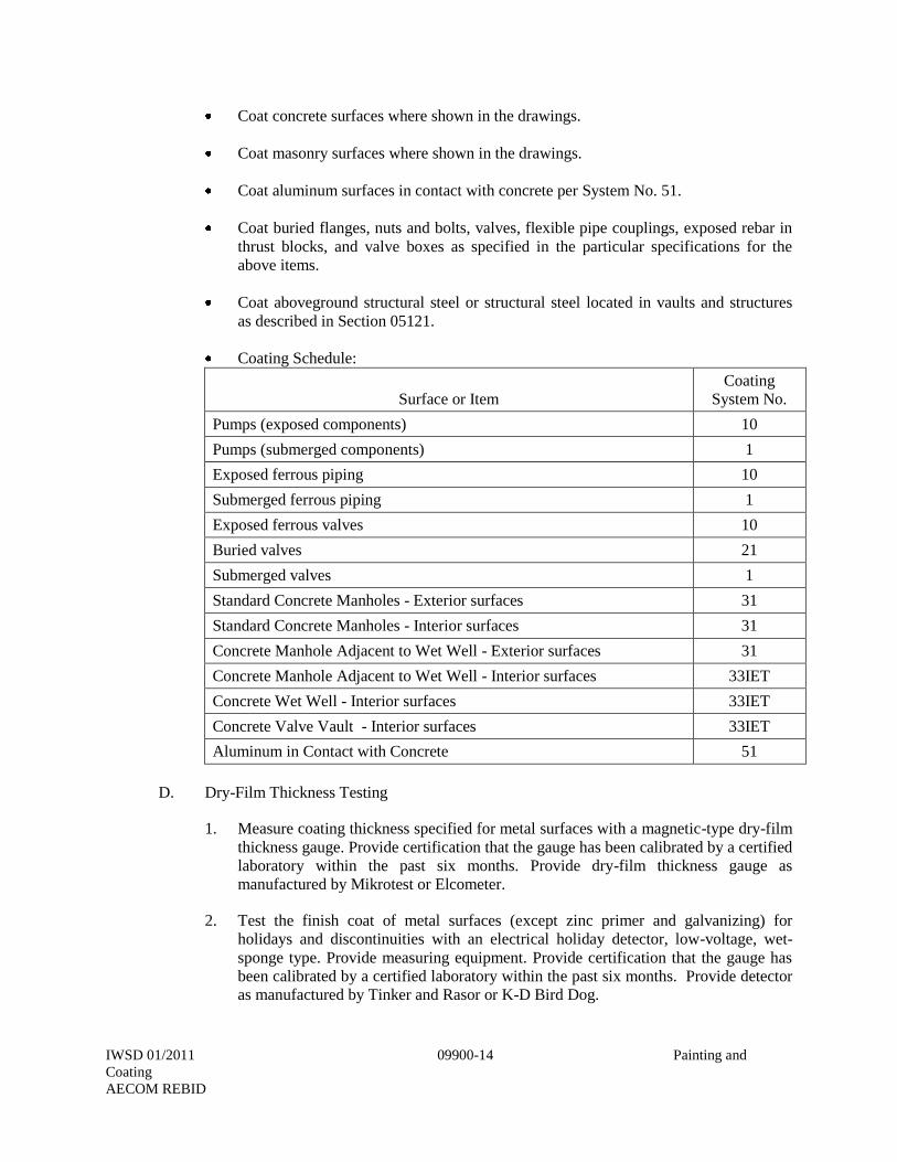
Coat concrete surfaces where shown in the drawings.
Coat masonry surfaces where shown in the drawings.
Coat aluminum surfaces in contact with concrete per System No. 51.
Coat buried flanges, nuts and bolts, valves, flexible pipe couplings, exposed rebar in
thrust blocks, and valve boxes as specified in the particular specifications for the
above items.
Coat aboveground structural steel or structural steel located in vaults and structures
as described in Section 05121.
Coating Schedule:
Surface or Item
Coating
System No.
Pumps (exposed components) 10
Pumps (submerged components) 1
Exposed ferrous piping 10
Submerged ferrous piping 1
Exposed ferrous valves 10
Buried valves 21
Submerged valves 1
Standard Concrete Manholes - Exterior surfaces 31
Standard Concrete Manholes - Interior surfaces 31
Concrete Manhole Adjacent to Wet Well - Exterior surfaces 31
Concrete Manhole Adjacent to Wet Well - Interior surfaces 33IET
Concrete Wet Well - Interior surfaces 33IET
Concrete Valve Vault - Interior surfaces 33IET
Aluminum in Contact with Concrete 51
D. Dry-Film Thickness Testing
1. Measure coating thickness specified for metal surfaces with a magnetic-type dry-film
thickness gauge. Provide certification that the gauge has been calibrated by a certified
laboratory within the past six months. Provide dry-film thickness gauge as
manufactured by Mikrotest or Elcometer.
2. Test the finish coat of metal surfaces (except zinc primer and galvanizing) for
holidays and discontinuities with an electrical holiday detector, low-voltage, wet-
sponge type. Provide measuring equipment. Provide certification that the gauge has
been calibrated by a certified laboratory within the past six months. Provide detector
as manufactured by Tinker and Rasor or K-D Bird Dog.
IWSD 01/2011 09900-15 Painting and
Coating
AECOM REBID
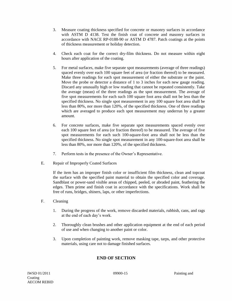
3. Measure coating thickness specified for concrete or masonry surfaces in accordance
with ASTM D 4138. Test the finish coat of concrete and masonry surfaces in
accordance with NACE RP-0188-90 or ASTM D 4787. Patch coatings at the points
of thickness measurement or holiday detection.
4. Check each coat for the correct dry-film thickness. Do not measure within eight
hours after application of the coating.
5. For metal surfaces, make five separate spot measurements (average of three readings)
spaced evenly over each 100 square feet of area (or fraction thereof) to be measured.
Make three readings for each spot measurement of either the substrate or the paint.
Move the probe or detector a distance of 1 to 3 inches for each new gauge reading.
Discard any unusually high or low reading that cannot be repeated consistently. Take
the average (mean) of the three readings as the spot measurement. The average of
five spot measurements for each such 100 square foot area shall not be less than the
specified thickness. No single spot measurement in any 100 square foot area shall be
less than 80%, nor more than 120%, of the specified thickness. One of three readings
which are averaged to produce each spot measurement may underrun by a greater
amount.
6. For concrete surfaces, make five separate spot measurements spaced evenly over
each 100 square feet of area (or fraction thereof) to be measured. The average of five
spot measurements for each such 100-square-foot area shall not be less than the
specified thickness. No single spot measurement in any 100-square-foot area shall be
less than 80%, nor more than 120%, of the specified thickness.
7. Perform tests in the presence of the Owner’s Representative.
E. Repair of Improperly Coated Surfaces
If the item has an improper finish color or insufficient film thickness, clean and topcoat
the surface with the specified paint material to obtain the specified color and coverage.
Sandblast or power-sand visible areas of chipped, peeled, or abraded paint, feathering the
edges. Then prime and finish coat in accordance with the specifications. Work shall be
free of runs, bridges, shiners, laps, or other imperfections.
F. Cleaning
1. During the progress of the work, remove discarded materials, rubbish, cans, and rags
at the end of each day’s work.
2. Thoroughly clean brushes and other application equipment at the end of each period
of use and when changing to another paint or color.
3. Upon completion of painting work, remove masking tape, tarps, and other protective
materials, using care not to damage finished surfaces.
END OF SECTION
IWSD 01/2011 09910-1 Manhole Lining System
AECOM REBID
SECTION 09910
MANHOLE LINING SYSTEM
PART 1 GENERAL
1.01 Summary
A. This specification covers labor, materials, equipment and services to install a manhole
lining system on existing concrete manholes and wetwells and new precast concrete
manholes and wetwells as indicated on the plans.
B. Related sections:
1. Section 01300 – Submittals
1.02 References
A. SSPC SP-13/Nace No. 6 – Surface Preparation of Concrete
B. ASTM – The published standards of the American Society for Testing and Materials, West
Conshohocken, PA.
C. NACE – The published standards of National Association of Corrosion Engineers (NACE
International) Houston, TX.
D. SSPC – The published standards of the Society of Protective Coatings, Pittsburgh, PA.
1.03 Submittals
A. Product Data
1. Technical data sheet on each product used.
2. Material Safety Data Sheet (MSDS) for each product used.
3. Copies of independent testing performed on the coating product indicating the product
meets the requirements as specified herein.
4. Technical data sheet and project specific data for repair materials to be topcoated with
the coating product(s) including application, cure time and surface preparation
procedures.
B. Contractor Data:
IWSD 01/2011 09910-2 Manhole Lining System
AECOM REBID
1. Current documentation from coating product manufacturer certifying contractor’s
training and equipment complies with the Quality assurance requirements specified
herein.
2. Five (5) recent references of coating contractor indicating successful application of
coating product(s) of the same material type as specified herein, applied by spray
application within the municipal wastewater environment.
1.04 Quality Assurance
A. Coating product(s) shall be capable of being installed and curing properly within a manhole
environment. Coating product(s) shall be resistant to all forms of chemical or
bacteriological attack found in municipal sanitary sewer systems; capable of adhering to the
manhole structure substrates.
B. Repair product(s) shall be compatible with coating product(s) including ability to bond to
form a composite system.
C. Utilize equipment for the spray application of the coating product(s) which has been
approved by the coating product manufacturer; and the equipment operator has received
training on the operation and maintenance of said equipment from the coating product
manufacturer.
D. Application Contractor shall be certified by the coating product manufacturer for the
handling, mixing, application and inspection of the coating product(s) to be used as
specified herein.
E. Inspectors shall be trained in the use of testing or inspection instrumentation and
knowledgeable of the proper use, preparation and installation of coating product(s) to be
used as specified herein.
F. Provide and enforce quality control procedures consistent with the coating product(s)
manufacturer recommendations and applicable NACE or SSPC standards as referenced
herein.
1.05 Delivery, Storage, And Handling
A. Materials are to be kept dry, protected from weather and stored under cover.
B. Protective coating materials are to be stored between 50° F and 90° F. Do not store near
flame, heat or strong oxidants.
C. Protective coating materials are to be handled according to their material safety data sheets.
1.06 Site Conditions
A. Conform to local, state and federal regulations including those set forth by OSHA, RCRA,
and the EPA and other applicable authorities.
B. Provide plans to Engineer for review for confined space entry, flow diversion and/or bypass
plans prior to performing the Work.
IWSD 01/2011 09910-3 Manhole Lining System
AECOM REBID
1.07 Special Warranty
A. Warrant work against defects in materials and workmanship for a period of ten (10) years,
unless otherwise noted, from the date of final acceptance of the project. Repair or replace,
within a reasonable time after receipt of written notice, defects in materials or workmanship
which may develop during said ten (10) year period and any damage to other work caused
by such defects or the repairing of same, at no expense to the OWNER.
PART 2 PRODUCTS
2.01 Existing Products
A. Standard Portland cement or new concrete (not quick setting high strength cement) must be
cured a minimum of 28 days prior to application of the coating product(s).
B. Remove existing coatings prior to application of the coating product(s) which may affect
the performance and adhesion of the coating product(s).
C. Thoroughly clean and prepare existing products to effect a seal with the coating product(s).
2.02 Repair And Resurfacing Products
A. Repair products shall be used to fill voids, bugholes, and/or smooth transitions between
components prior to the installation of the coating product(s). Repair materials must be
compatible with the specified coating product(s) and shall be used and applied in
accordance with the manufacturer’s recommendations.
B. Resurfacing products shall be used to fill large voids, lost mortar in masonry structures,
smooth deteriorated surfaces and rebuild severely deteriorated structures.
C. The following products may be accepted and approved as compatible repair and resurfacing
products for use within the specifications:
1. 100% solids, solvent-free epoxy grout specifically formulated for polyester resin
topcoating compatibility.
2. Factory blended, repair setting, high early strength, fiber reinforced, non-shrink repair
mortar that can be toweled or pneumatically spray applied may be acceptable if
specifically formulated to be suitable for topcoating with the specified coating
product(s).
2.03 Coating Products
A. Manufacturers: Integrated Environmental Technologies, Santa Barbara, California (805)
969-2292 or Raven Lining System, Tulsa, Oklahoma (800) 324-2810.
B. Product: IET – 100% solids, two component, highly modified polyester resin system or
Raven 405 System, a 100% solid ultra high build epoxy coating, meeting the following
minimum characteristics:
IWSD 01/2011 09910-4 Manhole Lining System
AECOM REBID
1. No adhesion-interfering shrinkage upon curing.
2. Compressive Strength, psi (ASTM D695): 15,000 (minimum)
3. Tensile Strength, psi (ASTM D638): 4,900 (minimum)
4. Flexural Modulus, psi (ASTM D790): 8,600 (minimum)
5. Impact Resistance (Specimen with Knotch): 10.0 Inch-Pounds
6. Impact Resistance (Specimen without Knotch): 4.5 Inch-Pounds
7. Barcol Hardness (Impressor #L25): 72 (minimum)
8. Adhesive Strength, psi: 1582
9. Chemical Resistance all types of service for:
a. Municipal sanitary sewer environment
b. Sulfuric acid, 25%
c. Hydrogen Sulfide Gas, All concentrations
d. Sodium hydroxide, 5%
2.04 Coating Application Equipment
A. Spray equipment shall be specifically designed to accurately ratio and apply the coating
products and shall be in good working order to create a monolithic seamless lining.
B. Hard to reach areas, primer application and touch-up may be performed using hand tools.
PART 3 EXECUTION
3.01 Examination
A. Comply with local, state and federal regulatory and other applicable agencies with regard to
environment, health and safety during work.
B. Structures to be coated shall be readily accessible.
C. New Portland cement concrete structures shall have cured a minimum of 28 days since
manufacture prior to commencing coating installation.
D. Any active flows shall be dammed, plugged or diverted as required to ensure all liquids are
maintained below or away from the surfaces to be coated.
E. Temperature of the surface to be coated should be maintained between 40° F and 120° F.
IWSD 01/2011 09910-5 Manhole Lining System
AECOM REBID
F. Shield surfaces to be coated to avoid exposure of direct sunlight or other intense heat
source. Where varying surface temperature does exist, schedule coating installation when
the temperature is falling versus rising.
G. Prior to commencing surface preparation, inspect surfaces to receive the coating and notify
Owner, in writing, of any noticeable disparity in the site, structure or surfaces which may
interfere with the work, use of materials or procedures as specified.
3.02 Surface Preparation
A. Oils, grease, incompatible existing coatings, waxes, form release, curing compounds,
efflorescence, sealers, salts, or other contaminants which may affect the performance and
adhesion of the coating to the substrate shall be removed.
B. Concrete and/or mortar damaged by corrosion, chemical attack or other means of
degradation shall be removed so that the only sound substrate remains.
C. Choice of surface preparation method(s) shall be based upon the condition of the structure
and concrete or masonry surface, potential contaminants present, access to perform work,
and required cleanliness and profile of the prepared surface to receive the coating
product(s).
D. Surface preparation method or combination of methods to be used include high pressure
water cleaning, high pressure water jetting, abrasive blasting, shotblasting, grinding,
scarifying, detergent water cleaning, hot water blasting and others described in NACE no.
6/SSPC SP-13. Whichever method(s) are used, they shall be performed in a manner that
provides a uniform, sound clean neutralized surface suitable for topcoating with the coating
product(s).
E. Infiltration shall be stopped by using a material which is compatible with the repair
products and is suitable for topcoating with the coating product(s).
F. Termination points of the coating product(s) shall be made at the bottom of the manhole
frame, and a minimum of 1” interfacing with each pipe penetration. The manhole frame
and casting shall not be coated.
3.03 Application Of Repair And Resurfacing Products
A. Areas where rebar has been exposed and is corroded shall be first prepared in accordance
with Section 3.02. The exposed rebar shall then be abrasive blasted and coated with coating
product specified.
B. Repair products shall be used to fill voids, bugholes, and other surface defects which may
affect the performance or adhesion of the coating product(s).
C. Resurfacing products shall be used to repair, smooth or rebuild surfaces with rough profiles
to provide a concrete or masonry substrate suitable for the coating product(s) to be applied.
These products shall be installed to minimum thickness as recommended within
manufacturers published guidelines.
IWSD 01/2011 09910-6 Manhole Lining System
AECOM REBID
D. Repair and resurfacing products shall be handled, mixed, installed and cured in accordance
with manufacturer guidelines.
E. Repaired or resurfaces shall be inspected for cleanliness and suitability to receive the
coating product(s). Additional surface preparation may be required prior to coating
application.
3.04 Application Of Coating Product(S)
A. Application procedures shall conform to the recommendations of the coating product(s)
manufacturer, including environmental controls, product handling, mixing, application
equipment and methods.
B. Spray equipment shall be specifically designed to accurately ratio and apply the coating
product(s) and shall be in proper working order.
C. Contractors qualified in accordance with Section 1.04 of these specifications shall perform
all aspects of coating product(s) installation.
D. Prepared surfaces shall be coated by spray application of the coating product(s) described
herein to a minimum wet film thickness of 200 mils.
E. Subsequent topcoating or additional coats of the coating product(s) shall occur within the
products recoat window. Additional surface preparation procedures will be required if this
recoat window is exceeded.
F. Coating product(s) shall interface with adjoining construction materials throughout the
manhole structure to effectively seal and protect concrete or masonry substrates from
infiltration and attack by corrosive elements. Procedures and materials to effect this
interface shall be as recommended by the coating product(s) manufacturer.
G. Termination points of the coating product(s) shall be made at the bottom of the manhole
frame, and a minimum of 1” interfacing with each pipe penetration. The manhole frame
and casting shall not be coated.
H. Manhole inverts shall be coated.
I. Sewage flow shall be stopped, bypassed or diverted for application of the coating product(s)
to the invert and interface with pipe material.
3.05 Testing And Inspection
A. During application a wet film thickness gauge, meeting ASTM D4414-Standard Practice
for Measurement of Wet Film Thickness of Organic Coatings by Notched Gages, shall be
used. Take measurements, document and attest to results and submit to Engineer.
B. After the coating product(s) have set in accordance with manufacturer instructions, surfaces
shall be inspected for holidays with high voltage holiday detection equipment. Reference
NACE RPO 188-99 for performing holiday detection. Detected holidays shall be marked
IWSD 01/2011 09910-7 Manhole Lining System
AECOM REBID
and repaired by abrading the coating surface with grit disk paper or other hand tooling
method. After abrading and cleaning, additional coating shall be hand applied to the repair
area. Touch-up/repair procedures shall follow the coating manufacturer’s recommendations.
Documentation on areas tested, results and repairs made shall be provided to the Engineer.
C. Visual inspection shall be made by the Engineer and/or Inspector. Deficiencies in the
finished coating shall be marked and repaired according to the specified procedures.
D. Return the sewer system to full operation after final inspection and acceptance of the Work.
END OF SECTION
IWSD 01/2011 09961-1 Fusion-Bonded Epoxy Linings And Coatings
AECOM REBID
SECTION 09961
FUSION-BONDED EPOXY LININGS AND COATINGS
PART 1 - GENERAL
1.01 Description
This section includes materials, application, and testing of one-part, fusion-bonded, heat-cured,
thermosetting, 100% solids epoxy linings and coatings on steel, cast-iron, and ductile-iron
equipment, such as valves, flexible pipe couplings, and structural steel.
1.02 Submittals
A. Submit shop drawings in accordance with the General Conditions, Section 01300, and the
following.
B. Submit manufacturer's catalog literature and product data sheets, describing the physical
and chemical properties of the epoxy coating. Describe application and curing procedure.
C. Submit coating application test records for measuring coating thickness and holiday
detection for each item or pipe section and fitting. Describe repair procedures used.
PART 2 - MATERIALS
2.01 Piping and Equipment Surfaces
A. Require equipment suppliers to provide equipment that is free of salts, oil, and grease to
the coating applicator.
B. Require pipe suppliers to provide bare pipe that is free of salts, oil, and grease to the
coating applicator.
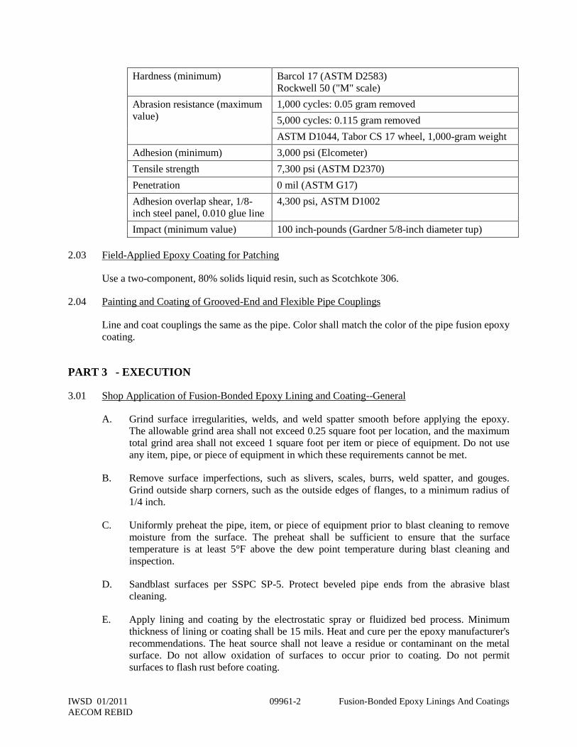
2.02 Shop-Applied Epoxy Lining and Coating
Lining and coating shall be a 100% solids, thermosetting, fusion-bonded, dry powder epoxy
resin: Scotchkote 134 or 206N, Lilly Powder Coatings "Pipeclad 1500 Red," H. B. Fuller 1F-
3003, or equivalent. Epoxy lining and coating shall meet or exceed the following requirements:
IWSD 01/2011 09961-2 Fusion-Bonded Epoxy Linings And Coatings
AECOM REBID
Hardness (minimum) Barcol 17 (ASTM D2583)
Rockwell 50 ("M" scale)
Abrasion resistance (maximum
value)
1,000 cycles: 0.05 gram removed
5,000 cycles: 0.115 gram removed
ASTM D1044, Tabor CS 17 wheel, 1,000-gram weight
Adhesion (minimum) 3,000 psi (Elcometer)
Tensile strength 7,300 psi (ASTM D2370)
Penetration 0 mil (ASTM G17)
Adhesion overlap shear, 1/8-
inch steel panel, 0.010 glue line
4,300 psi, ASTM D1002
Impact (minimum value) 100 inch-pounds (Gardner 5/8-inch diameter tup)
2.03 Field-Applied Epoxy Coating for Patching
Use a two-component, 80% solids liquid resin, such as Scotchkote 306.
2.04 Painting and Coating of Grooved-End and Flexible Pipe Couplings
Line and coat couplings the same as the pipe. Color shall match the color of the pipe fusion epoxy
coating.
PART 3 - EXECUTION
3.01 Shop Application of Fusion-Bonded Epoxy Lining and Coating--General
A. Grind surface irregularities, welds, and weld spatter smooth before applying the epoxy.
The allowable grind area shall not exceed 0.25 square foot per location, and the maximum
total grind area shall not exceed 1 square foot per item or piece of equipment. Do not use
any item, pipe, or piece of equipment in which these requirements cannot be met.
B. Remove surface imperfections, such as slivers, scales, burrs, weld spatter, and gouges.
Grind outside sharp corners, such as the outside edges of flanges, to a minimum radius of
1/4 inch.
C. Uniformly preheat the pipe, item, or piece of equipment prior to blast cleaning to remove
moisture from the surface. The preheat shall be sufficient to ensure that the surface
temperature is at least 5°F above the dew point temperature during blast cleaning and
inspection.
D. Sandblast surfaces per SSPC SP-5. Protect beveled pipe ends from the abrasive blast
cleaning.
E. Apply lining and coating by the electrostatic spray or fluidized bed process. Minimum
thickness of lining or coating shall be 15 mils. Heat and cure per the epoxy manufacturer's
recommendations. The heat source shall not leave a residue or contaminant on the metal
surface. Do not allow oxidation of surfaces to occur prior to coating. Do not permit
surfaces to flash rust before coating.
IWSD 01/2011 09961-3 Fusion-Bonded Epoxy Linings And Coatings
AECOM REBID
3.02 Shop Application of Fusion-Bonded Epoxy Lining and Coating to Pipe--Additional Requirements
A. Apply lining and coating per AWWA C213 except as modified herein.
B. Grind 0.020 inch (minimum) off the weld caps on the pipe weld seams before beginning
the surface preparation and heating of the pipe.
3.03 Shop Application of Fusion-Bonded Epoxy Lining and Coating to Joint Areas of Ductile-Iron and
Cast-Iron Fittings--Additional Requirements
Limit the protective coating thickness in the joints of ductile-iron and cast-iron fittings to
maintain a leak-proof joint. However, the coating thickness in the joint area shall not be less than
4 mils.
3.04 Quality of Lining and Coating Applications
The cured lining or coating shall be smooth and glossy, with no graininess or roughness. The
lining or coating shall have no blisters, cracks, bubbles, underfilm voids, mechanical damage,
discontinuities, or holidays.
3.05 Factory Testing of Coating--General
A. Test linings and coatings with a low-voltage wet sponge holiday detector. Test pipe linings
and coatings per AWWA C213, Section 5.3.3. If the number of holidays or pinholes is
fewer than one per 20 square feet of coating surface, repair the holidays and pinholes by
applying the coating manufacturer's recommended patching compound to each holiday or
pinhole and retest. If the number of pinholes and holidays exceeds one per 20 square feet
of coating surface, remove the entire lining or coating and recoat the item or pipe.
B. Measure the coating thickness at three locations on each item or piece of equipment or pipe
section using a coating thickness gauge calibrated at least once per eight-hour shift. Record
each measured thickness value. Where individual measured thickness values are less than
the specified minimum thickness, measure the coating thickness at three additional points
around the defective area. The average of these measurements shall exceed the specified
minimum thickness value, and no individual thickness value shall be more than 2 mils
below or 3 mils above the specified minimum value. If a section of the pipe, item, or piece
of equipment does not meet these criteria, remove the entire lining or coating and recoat
the entire item or piece of equipment.
3.06 Factory Testing of Lining and Coating of Pipe--Additional Requirements
Check for coating defects on the weld seam centerlines. There shall be no porous blisters, craters,
or pimples lying along the peak of the weld crown.
3.07 Field Repairs
Patch scratches and damaged areas incurred while installing fusion-bonded epoxy coated items
with a two-component, 80% solids (minimum), liquid epoxy resin. Wire brush or sandblast the
damaged areas per SSPC SP-10. Lightly abrade or sandblast the coating or lining on the sides of
the damaged area before applying the liquid epoxy coating. Apply a two-part epoxy coating to
defective linings and coatings to areas smaller than 20 square inches. Patched areas shall overlap
IWSD 01/2011 09961-4 Fusion-Bonded Epoxy Linings And Coatings
AECOM REBID
the parent or base coating a minimum of 0.5 inch. If a defective area exceeds 20 square inches,
remove the entire lining and coating and recoat the entire item or piece of equipment. Apply the
liquid epoxy coating to a minimum dry-film thickness of 15 mils.
END OF SECTION
IWSD 01/2011 09971-1 Ceramic Epoxy Lining For Ductile-Iron Pipe
AECOM REBID
SECTION 09971
CERAMIC EPOXY LINING FOR DUCTILE-IRON PIPE
PART 1 - GENERAL
1.01 Description
This section includes materials, application, and testing of an amine-cured ceramic epoxy,
formulated for use as an internal lining for ductile-iron pipe and fittings.
1.02 Related Work Specified Elsewhere
A. Section 02674 – Underground Piping Systems.
1.03 Submittals
A. Submit shop drawings in accordance with the General Conditions, Section 01300 and the
following:
B. Submit manufacturer's data sheets showing the following information:
1. Percent solids by volume.
2. Recommended surface preparation.
3. Recommended thinners.
4. Application instructions including recommended equipment and temperature
limitations.
5. Curing requirements and instructions.
C. Provide submittal identifying the type and gradation of abrasives used for surface
preparation.
PART 2 - MATERIALS
2.01 Ceramic Epoxy Lining
A. The lining shall be high-solids, solvent-free, fast-curing two-component ceramic epoxy
formulated especially to line the interior of ductile-iron pipe. Product: Protecto 401
ceramic epoxy.
B. The material shall be an amine-cured novalac epoxy containing at least 20% by volume of
ceramic quartz pigment.
C. The lining material shall have the following characteristics:
IWSD 01/2011 09971-2 Ceramic Epoxy Lining For Ductile-Iron Pipe
AECOM REBID
1. A permeability rating of 0.00 when tested according to Method A of ASTM E96,
Procedure A with a test duration of 30 days.
2. ASTM B117, Salt Spray (Scribed Panel): Results to equal 0.0 undercutting after two
years.
3. ASTM G95, Cathodic Disbondment: 1.5 volts at 77°F. Results to equal no more
than 0.5 mm undercutting after 30 days.
4. Immersion Testing Rated Using ASTM D714:
a. 20% Sulfuric Acid: No effect after two years.
b. 140°F 25% Sodium Hydroxide: No effect after two years.
c. 160°F Distilled Water: No effect after two years.
d. 120°F Tap Water (Scribed Panel): 0.0 undercutting after two years with no
effect.
5. An abrasion resistance of no more than 3 mils (0.075 mm) loss after one million
cycles using European Standard EN 598, Section 7.8.
2.02 Ceramic Epoxy Joint Compound
Use a brushable novalac epoxy designed for sealing cut ends and repairs when pipes are lined
with ceramic epoxy. Use this material on spigots and in bell sockets only after the pipe or fitting
is lined with ceramic epoxy. Protecto joint compound can be used over Protecto 401 or on bare
substrate. Do not apply Protecto 401 over Protecto joint compound.
2.03 Abrasives for Surface Preparation
Abrasives used for preparation of iron surfaces shall comply with NAPF 500-03-04 and shall be
one of the following:
A. 16 to 30 or 16 to 40 mesh silica sand or mineral grit.
B. 20 to 40 mesh garnet.
C. Crushed iron slag, 100% retained on No. 80 mesh.
D. SAE Grade G-40 or G-50 iron or steel grit.
PART 3 - EXECUTION
3.01 Surface Preparation for Ceramic Epoxy Lining
A. Deliver pipe to the lining applicator bare. Because removal of old linings may not be
possible, the intent of this specification is that the entire interior of the ductile-iron pipe or
fitting shall not have been lined with any substance prior to the application of the specified
lining material.
IWSD 01/2011 09971-3 Ceramic Epoxy Lining For Ductile-Iron Pipe
AECOM REBID
B. Abrasive blast the entire pipe surface to be lined per NAPF 500-03-04 (special internal
linings). Abrasive blast the interiors of fittings per NAPF 500-03-05, Blast Clean No. 1.
3.02 Surface Preparation for Ceramic Epoxy Joint Compound
The surface preparation shall be equal to the specifications for the project or as outlined in the
touch-up procedure. Do not apply Protecto joint compound over wet or frozen surfaces.
3.03 Lining Pipe with Ceramic Epoxy
A. After surface preparation and within eight hours, line the entire interior surface up to the
gasket groove, with the exception of the spigot end, with an average of 40 mils, 35 mils
minimum, of ceramic epoxy. If any rusting is apparent prior to lining the surface, reblast
the entire area.
B. Within eight hours of surface preparation, the interior of the pipe shall receive the specified
dry-film thickness of the ceramic epoxy. No lining shall take place when the substrate or
ambient temperature is below 40°F. The surface shall be dry and dust free. If flanged pipe
or fittings are included in the project, do not apply the lining on the faces of the flanges.
3.04 Coating of the Pipe Ends with Ceramic Epoxy – Gasketed Joints
Due to the tolerances involved, coat the spigot end from the gasket area to the end of the spigot
with 6 mils average, 10 mils maximum of Protecto joint compound ceramic epoxy. The ceramic
epoxy coating shall be smooth without excess buildup on the spigot end. Apply the joint
compound by brush to ensure coverage. Coat the gasket seat and spigot ends after the application
of the lining.
3.05 Factory Testing of Lining
A. Check the film thickness of the ceramic epoxy lining using a magnetic film thickness
gauge. Take measurements per SSPC PA2 Section 5.1.
B. Test the coated areas of the pipe from the socket edge area of the spigot back to the bell
face for pinholes using a 2,500-volt pinhole detection test. Repair any pinholes found prior
to shipment.
3.06 Thickness Measurement at Place of Manufacture
A. Test linings per NACE SP0188-2006 with a high-voltage holiday detector set at the voltage
per NACE SP0188-2006, Table 1. If the number of holidays or pinholes is fewer than one
per 25 square feet of coating surface for internal coatings and one per 10 square feet for
external coatings, repair the holidays and pinholes by applying the coating manufacturer's
recommended patching compound to each holiday or pinhole and retest. If the number of
pinholes and holidays exceeds the above criteria, remove the entire lining and recoat the
item or pipe at the place of manufacture. Recoating will be permitted if the material has
cured less than the manufacturer's recommended cure time.
B. Measure the coating thickness on each pipe section using a coating thickness gauge
calibrated at least once per eight-hour shift. Make five separate spot measurements
(average of three readings) spaced evenly over each 100 square feet of area (or fraction
IWSD 01/2011 09971-4 Ceramic Epoxy Lining For Ductile-Iron Pipe
AECOM REBID
thereof) to be measured. Make three gauge readings for each spot measurement of either
the substrate or the paint. Move the probe a distance of 1 to 3 inches for each new gauge
reading. Discard any unusually high or low gauge reading that cannot be repeated
consistently. Take the average (mean) of the three gauge readings as the spot measurement.
The average of five spot measurements for each such 100-square-foot area shall not be less
than the specified thickness. No single spot measurement in any 100-square-foot area shall
be less than the specified minimum thickness. One of three readings averaged to produce
each spot measurement may under run by a greater amount. If a section of the pipe, item,
or piece of equipment does not meet these criteria, remove the entire coating and recoat the
entire item or piece of equipment.
C. Thickness determinations shall meet the following requirements:
1. No individual reading shall be below the specified minimum.
2. Individual spot readings (consisting of three-point measurements within 3 inches of
each other) shall have an average not less than the specified average thickness.
3. The average of all spot readings shall be equal to or greater than the minimum
thickness specified.
D. Thickness determinations shall be conducted using a Type 1 or 2 thickness gauge as
described in SSPC PA2 specification.
3.07 Repair of Improperly Coated Surfaces at Place of Manufacture
If the item has an insufficient film thickness and the coating material curing time has not been
exceeded, clean and topcoat the surface with the specified repair coating to obtain the specified
coverage. Sandblast or power-sand visible areas of chipped, peeled, or abraded coating,
feathering the edges. Then recoat in accordance with the specifications. Work shall be free of
runs, bridges, shiners, laps, or other imperfections.
3.08 In-Plant Inspection and Testing by Owner's Representative
A. An Owner's Representative may inspect pipe, fittings, and lining and other material during
fabrication at the mill, production plant, or shop. The Owner's Representative shall be
allowed complete and unlimited access to all parts of the work and shall be furnished with
such information and assistance as is required to make a complete and detailed inspection.
Notify the Owner at least seven days prior to beginning of material production and
application.
B. The Owner may conduct tests to determine the integrity of the lining. Pipe and fittings
shall be available onsite and accessible at least three days before installation to allow time
for the Owner's tests. If the test results indicate any manufacturing defect, the material shall
be repaired or replaced at no extra cost to the Owner. The Owner's Representative will
make a determination on whether to repair or reject defective or damaged pipe or fitting.
3.09 Manufacturer Testing and Certification
Deliver every section of pipe and fitting with certified test results of that individual pipe
section or fitting. If a pipe or fitting is not accompanied by such certifications or does not
IWSD 01/2011 09971-5 Ceramic Epoxy Lining For Ductile-Iron Pipe
AECOM REBID
meet the Owner-conducted tests as described above, the pipe or fitting will be rejected.
3.10 Field Repair and Touch Up
A. Repair any areas where damage has occurred due to handling using the same ceramic
epoxy prior to installation as the original lining. Apply at a film thickness of 40 mils dry.
B. Apply product only if the substrate temperature and ambient air temperature is above 45°F
and is expected not to drop below 45°F for at least two hours after application. The
substrate temperature shall be 5°F above the dew point for a period of at least two hours
after application to avoid condensation occurring on wet paint. Do not apply ceramic
epoxy over wet or frozen surfaces. Overcoat with the same material as specified above.
3.11 On-Site Storage
A. Handle pipe with belt slings and padded forks to avoid damage. Pad shipping timbers and
straps when shipping pipe and fittings.
B. The maximum delivery, storage, and installation time allowed for pipe and fitting is 120
days from the date they were lined to the date they are installed. Any pipe not meeting this
requirement will be rejected.
3.12 Handling
Handle lined pipe and fittings only from the outside of the pipe and fittings. Do not place forks,
chains, straps, hooks, etc., inside the pipe and fittings for lifting, positioning, or laying. Do not
drop the pipe or unload by rolling. Do not let the pipe strike sharp objects while swinging or
being off loaded. Do not place pipe on grade by use of hydraulic pressure from an excavator
bucket or by banging with heavy hammers.
3.13 Procedures for Sealing Cut Ends and Repairing Field-Damaged Areas of Lined Pipe and Fittings
A. Remove burrs caused by field cutting of ends or handling damage and smooth out the edge
of the lining if rough. Remove traces of oil, grease, asphalt, dust, dirt, etc.
B. Remove any damaged lining caused by field cutting operations or handling and clean any
exposed metal by sanding or scraping. Sandblasting or power tool cleaning roughening is
also acceptable. Remove any loose lining by chiseling, cutting, or scraping into well-
adhered lined area before patching. Overlap at least 1 inch of lining in the area to be
repaired.
C. With the area to be sealed or repaired clean and roughened, apply a coat of Protecto joint
compound.
D. Coat the entire freshly cut exposed metal surface of the cut pipe end. To ensure proper
sealing, overlap at least 1 inch of the lining with this repair material.
IWSD 01/2011 09971-6 Ceramic Epoxy Lining For Ductile-Iron Pipe
AECOM REBID
3.14 Joint Installation
A. Push ductile-iron pipe lined with ceramic epoxy only when using a restrained joint system
that does not allow the spigot to contact the bell shoulder. The pipe may be pulled using
restrained joint pipe or restraining gaskets as restraints. Do not push the restraining gaskets.
Do not home pipe all the way to the bell shoulder with restraining gaskets. Do not push or
pull ductile-iron pipe lined with ceramic epoxy using any technique that may damage the
lining.
B. Do not pull metal mandrels through ceramic-epoxy lined ductile-iron pipe.
3.15 Pipe Cleaning
Do not use pressure washing techniques to clean pipe lined with ceramic epoxy.
END OF SECTION
Recommended