W MULTI-SENSOR SYSTEM (MUSS)
FOR AIRBORNE SURVEILLANCE
OF INSHORE WATERS
G. D. Hickman
1,97
Technical report prepared under Contract N000!4-76-C-l042sponsored by the Office of Naval Research, Code 462.
Reproduction in whole or in part is permitted for anypurpose of the, United States Government. This documenthas been approved for public release and sale; itsdistribution is unlimited.
November 1977
Applied Science Technology,. Inc.1011 Arlington BoulevardArlington, Virginia 22209
S r.".,.-.. .. . .

ACKNOWLEDGMENTS
The author would like to acknowiedge Dr. James Bailey,
Office of Naval Research (Code 462), for supplying the
necessary funds and guidance to complete this project. The
author would also like to express his 3incere appreciation to
the many people who contributed their time in supplying the
information on the various remote sensors described in this
report.
•Crr -"-
•L,$ !
1;2--
TABLE OF CONTENTS
Pages
I. Introduction 1
II. Sensors 5
A. Microwave hadinineters (passive; non-imaging) 7
B. Radars (active; imaging) 8
C. Optical Multispectral Spectrometers 16(pasmive, imaging)
D. In.zdred Scanners (passive; imaging) 16
E. Infrared Radiometers/Spectrometers 20(passive; non-imaging)
F. C&meras
1. Mapping Frame Camera 22
2. Frame Reconnaissance Camera 23
3. Panoramic Camera 24
4. Strip Camera 25
5. Hybrid Cameras 28
a. Multiband Cameras 28b. Day/Night Laser Camera 29c. Solid State Camera System 30
G, Active Laser Systems 31
Ili. Summary 34
I, Conclusions/Recommendations 36
- -~-~ "

ABSTRACT
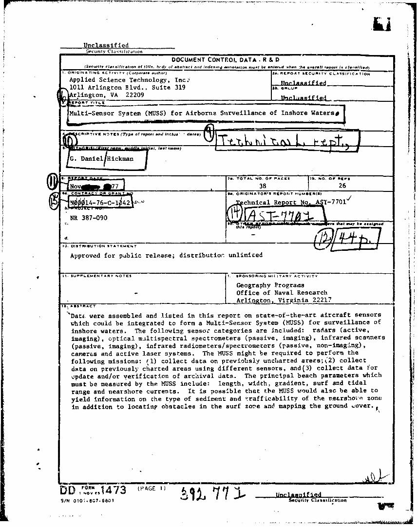
Data were assembled and listed in this report on state-of-
the-*rt aircraft sensors which could be integrated to form a
Multi-Sensor System (MUSS) for surveillance of inshore waters.
The following sensor categories are included: radars (active,
imaging), optical multispectral spectrometers (passive, imaging),
infrared scanners (passive, imaging), infrared radiometers/
upectrometers (passive, non-imaging), cameras and active laser
systems. The MUSS might be required to perform the following
missions: 1) collect data on previously uncharted areas; 2)
collect data on previously charted areas using different sensors,
and 3) collect dati for update and/or verification of archival
data. The principal beach parameters which must be measured by
the MUSS include: length, width, gradient, surf and tidal range
and nearshore currents. It is possible that the MUSS would
also be able to yield information on the type of sediment and
trafficability of the nearshore zone in addition to locating
obstacles in the surf zone and mapping the ground cover.
MULTI-SENSOR SYSTEM (MUSS) FOR
AIRBORNE SURVEILLANCE nF INSHORE WATERS
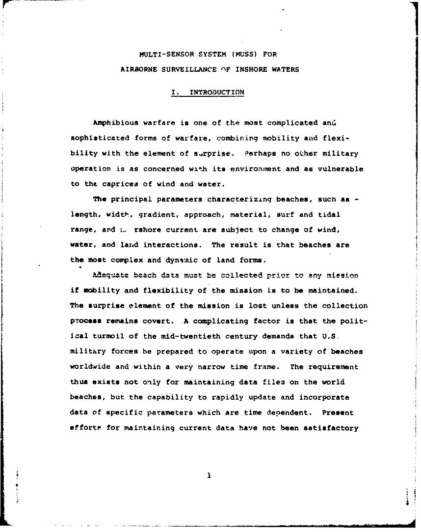
I. INTRODUCTION
Amphibious warfare is one of the most complicated ant
sophisticated forms of warfare, combining mobility anid flexi-
bility with the element of ssrprise. Perhaps no other military
operation is as concerned with its environment and as vulnerable
to the caprices of wind and water.
The principal parameters characterizing beaches, such as -
length, widtih, gradient, approach, material, surf and tidal
range, and L. rshore current are subject to change of wind,
water, and land interactions. The result is that beaches are
the most complex and dyn'inic of land forms.
aRAc-qugae bDea Ch. A-a tuavii* -m^*^ A nv 11,.- nr, 4-n ^nvP ra i a ann
if mobility and flexibility of the mission is to be maintained.
The surprise element of the mission is lost unless the collection
pTocess remains covert. A complicating factor is that the polit-
ical turmoil of the mid-twentieth century demands that U.S,
military forces be prepared to operate upon a variety of beaches
worldwide and within a very narrow time frame. The requirement
thus exists not only for maintaining data file3 on the world
beaches, but the capability to rapidly update and incorporate
data of specific parameters which are time dependent. Present
effortr for maintaining current data have not been satisfactory
1
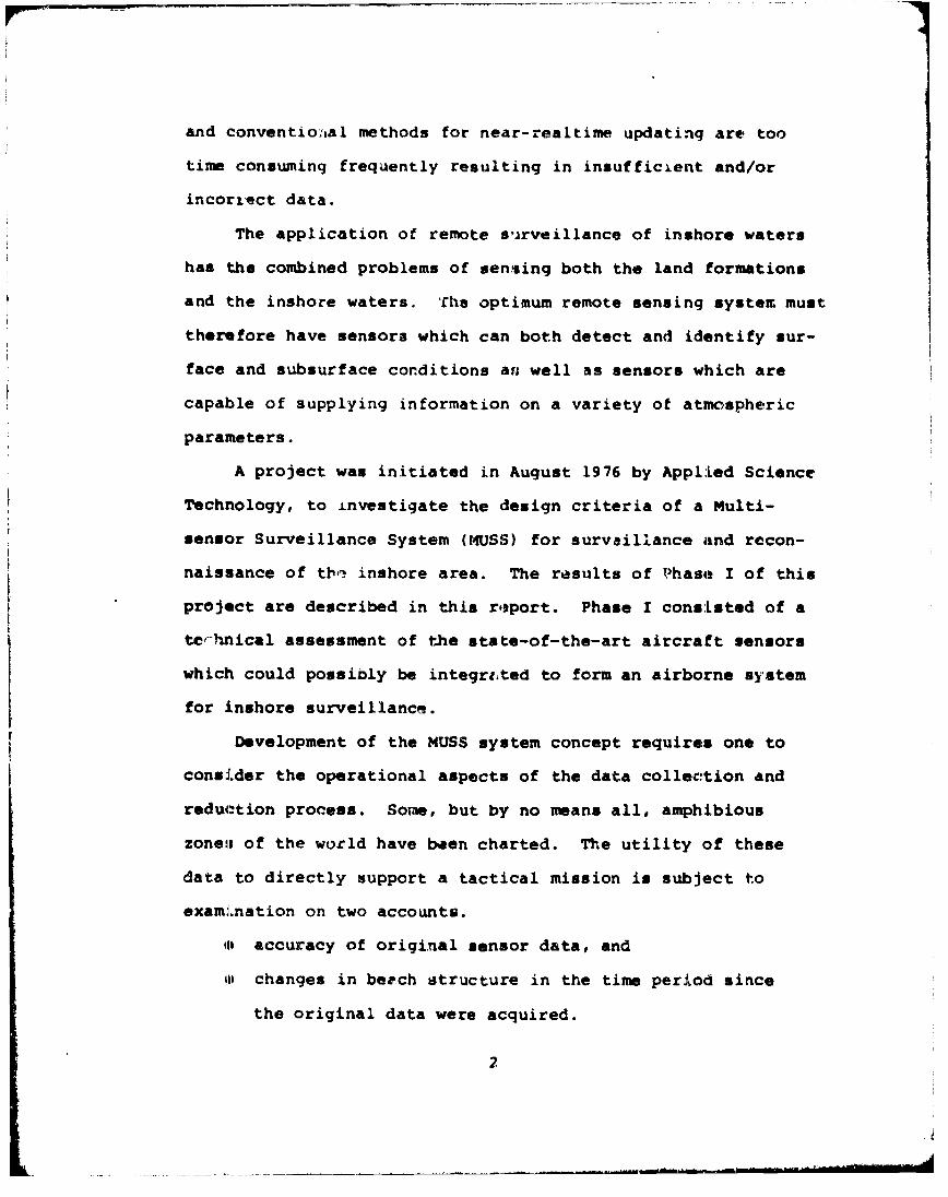
and conventio:aal methods for near-realtime updating are too
time consuming frequently resulting in insufficient and/or
incorrzect data.
The application of remote s',rveillance of inshore waters
has the combined problems of sensing both the land formations
and the inshore waters. The optimum remote sensing system must
therefore have sensors which can both detect and identify sur-
face and subsurface conditions ans well as sensors which are
capable of supplying information on a variety of atmospheric
parameters.
A project was initiated in August 1976 by Applied Science
Technology, to investigate the design criteria of a Multi-
sensor Surveillance System (MUSS) for survaillance and recon-
naissance of tb,, inshore area. The results of Phas4e I of this
project are described in this report. Phase I consisted of a
terhnical assessment of the state-of-the-art aircraft sensors
which could possibly be integreted to form an airborne system
for inshore surveillance.
Development of the MUSS system concept requires one to
consider the operational aspects of the data collection and
reduction process. Some, but by no means all, amphibious
zoneas of the world have been charted. The utility of these
data to directly support a tactical mission is subject to
examiLnation on two accounts.
"Il accuracy of original sensor data, and
"•ii changes in beech structure in the time period since
the original data were acquired.
2
Such archival data can be useful in developing predictive
models of beaches, particularly if measurements are repeated
over a period of time. It is possible, therefore, to derive a
set of viable beach parameters. The use of either the archival
or derived data in a tactical mission requires that such data
be verified and updat- 1 just prior to the mission.
To sumnmarize; the MUSS will be required to perform the
"aollowing types of missions:
e collect new data, area previouslv uncharted,
0 collect new data, area previously charted using
different sensors, and
e collect data for update and/or verification of
archival data.
Three levels of priority for inshore surveillance have
been stated by the Office of Naval Research. These priority £LU,&ins aa aubnown in Tabla i. The application of the various
se sors considered in this study have been included in this
table. Final sensor seloction must correlate the state-of-
the-art sensors with these requirements.
3
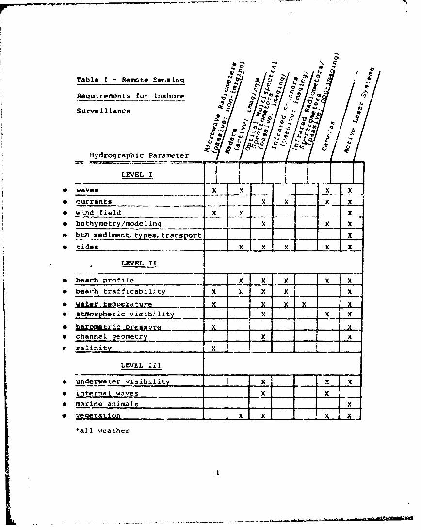
Table I - Remote Sersirq C 4 C
Requirements for Inshore cj
Surveillance A
CJ V
tlydrograpb ic Parameter
LEVEL I
e waves
* currents X - -x
e wLnd field Y " X
e bathymetry/modeling X _ X
* btn sediment, types, transport X
* tides _ x_.
LEVEL II
o beach profile - _x A x x
e beach trafficabil-.ty x X X X X* ~ .L~I L~llf... II. - ........ ~..L .L -
*water teM u Z - A - x* atnwospheric visib4,1ity ! Ix -
* barometric xr~ssvre - - -
e channel geometry I x
e salini~ty___ x_________
LEVEL I1iI
& underwater visibility X . x
a internal waves ____,,Ix x
e marine animals -
e ve•etition - x x - -
*all weather
i4
II. SENSC!.S
A number of devices, both imaqinq arid non-imaqinq, known
collectively as "remote sensors", have been and are currently
being developed to measure electromaqnetic radiation emitted
or reflected from the earth at various frequencies, angles,
polarizations, etc. These instruments are also currently
being used aboard many satellites and spacecraft.
The -nultispectral concept qenerlly states that the
level ')f energy reflected or emitted from objects normally
v,4rie with wavelength throughout the elmct,:omagnetic spectrum.
A unique signature of a•; object can therefore often be identi-
fied if the energy that 'b being reflected and/or emitte*( from
it is separated into carefully chosen wavelength bands. Many
cofiventional systems with a wide ranqe of sensitivity tend to
inhibit object.-tc-backgqround discrimination, however, discrim-
ination capability can generally be improved by selectively
recr'zding energy from within different wavelength bands.
While this irultispectral imaging technique may appear to
be relatively simple, complications arise owing to qncertainties
or variations related to the following factors:
o spectral characteristics of the source emitter,
* the a igle of incidence of the emitter with respect
to the surface,
e selective transmission, reflf-tion, absorption,
emission, and scattering effects of the atmosphere,
5
o reflectance and emittance characteristics of the
surface,
o altitude of the sensor platform,
# data collection, processinq, and presentation
techniques, and
o data Interpretation techniques.
An understanding of these factors and the uncertainties asqo-
ciated with their distribution, measurement, and relative
importance is -.ecessary in order to enhance the ob)ect-to-
background contra3g: ratio in any rernote sensinq oper&•icin.
Voiumnous data have beor, obtained duriing #he past decad in
a wide variety of di -iplines with numerous types of sentors.
The majority o! the sensors used are those that produce imwqgezy
or photography in the wavelength bands betwen n.3 micrometers
in'the near ultraviolet to apprcxinate~y 1.3 ma..ers in i-h.
microwave portion of the spectrum. Wit.hin this relatively broad
band, sensing Pystems may include the use of cameras; optical,
infrared and microwavve scanners, spectrometers and radiometers;
as well as active laser systems. With the exception of radars
and lasers, which are active systems providinq their own source
of i.lumination, the systems operating in the bands mentioned
above are qenerally passive; that is, they record the natural
level of radiation frzm a given scene.
The following is a list of the senpor categories for
which data were assembled during this contract.
- microwave radiometers (passive; non-imaging)
6
e radars (active; imaginq)
* optical multispectral spectrometers (passive, imaging)
* infrared scanners (passive; imaging)
* infrared! radiometers/spectrometers (passive; non-imaging)
* camoLas
* a=tive laser systems
A brief description of each sensor category is given, along
with the salient parameters for the specific sensor systems in
that category. Information for this study was assembled from
a variety of sources: personal contact with key scientists
and marketing managers, NASA centers, Marine Corps and Navy
peroonnel, private companies, conferences, specification
sheeta, and technical reports and handbooks.
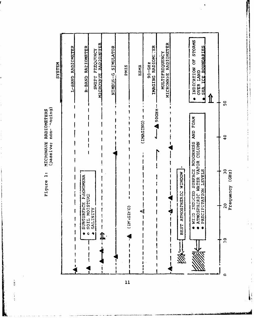
A., Microwave Radiometers (passive; non-imaging)rw-- •a diometry holds promise as a passive all-wcather
technique; it may have improved capabilities over shorter wave-
length sensing in detection of: ground moisture, ocean-wave
heights, and near s rface temperatures. Generally, the wave-
lengths longer than 10cm are surface penetrating and provide
good masurements of subsurface phenomena, soil moisture and
salinity. Wavelengths between 4 and 6cm provide the best
window through the atmosphere to the surface. Wavelengths
between 0.7) and 6crn are utilized to distinguish between temp-
eZature and emittance effects in the energy source such as
wind induced surface roughness and foam, the atmospheric
7
water vapor column, and precipitation levels. Wavelengths
below about 0.6 cm (750GHz) are most useful in providing indi-
cation of storms over land and of sea ice boundaries because
of their finer resolutions for a given antenna size or in
providing temperature, humidity and pressure soundinq due to
differential effects on specific absorption lines.
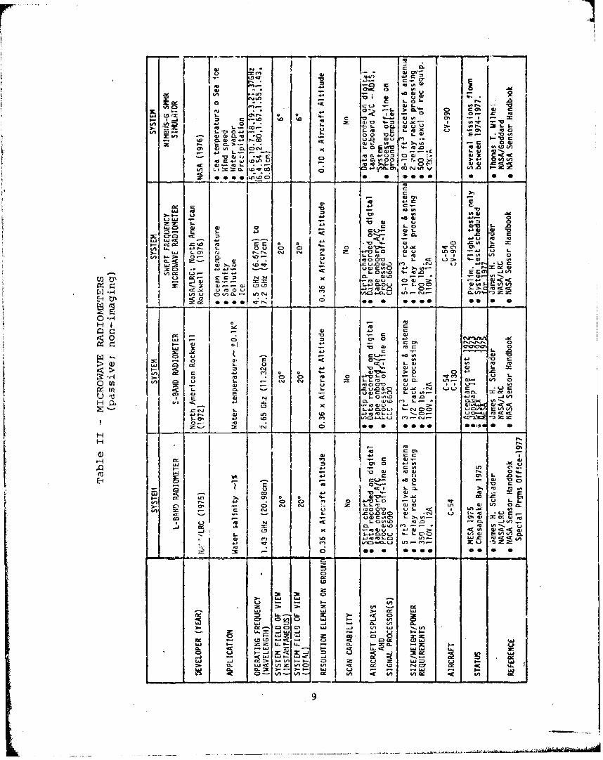
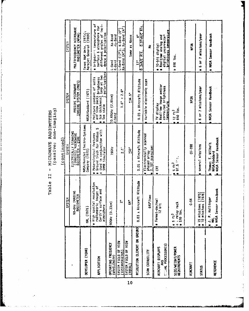
Table II lists the various microwave radiometers that were
identified by this study while figure 1 shows these same systems
superimposed on the various atmospheric bands. The majority ot
the passive microwave systems are large and weigh in access of
400 lbs. The only exceptions to this are 1) the S-Band radio-
meter of North American Rockwell, 2) the swept frequency micro-
wave radiometer of North American Rockwell, and 3) the elec-
trically scanning (imaging) microwave radiometer of Aerojet
General.
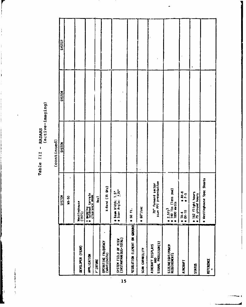
B. Radars (active; imaging)
Radars exist in many different confiqurations, each
designed to perform specific measurements on an illuminated
scene. The type of radar which appears to offer the most
potential for airborne remote sensing applications is desig-
nated as the Side Looking Airborne Radar (SLAR) systems. SLAR
systems can be divided into two basic classes; a) real-aperature
or non-coherent radar and b) Syrthetic Aperture Radar (SAR) or
coherent radar.
Radar provides a specular reflection from smooth objects.
8
c Is
O JL w u x
EU d Ul In 0 0 0 la 0
V ~ L.'w I-E U Q) m% r - 0 0:
CDO4. 04 00 vm 4-G -V *.0 L V
- _ 4.E L..- > C
-c 4 I-U *.I- C) , 1UU~L 0~ 0)8
a a 000 0~sC 0 a
-1 G)1
f.lC- 0 Cl4
LU 4U 1- Eui %")-- 4, Q1 in *4 L .
£J1i 2 F 1- (D0 0,) 4
Lii =0 : 0-.r > = .CL~4 4- C).) O'A.1) 4)
41 .i.I S- ug-E z:> 0 EU)- u
in Li. 4-iI L 0 0 0 JE- Un>- &i) 5-O fS '1- c'J cli A2; L. CJ0 cu ~ --0 i S. .V) ~0.- C. 10- mL' L. m U L/) 0
CL- F mo0. Lr - u)~ 4I-a) r, LC * u. U.4J.~) Q cm C) 4, .IJC
ccJ C- $- CVý0 4- if.-4,4 c N N . M ,a) %0 L-U~ *
-M -- a-O in-2.L..= ajcmQ) P; C tD L(-. m
U to 1 3 C
NC u C) 8)>, I4i 010 C4VL C -LU n0 )4 ý
4, -~ 0C 'JJ.-Li. a o .00 00UC 0
-z C C..~f )
2p 0'- 41 4,'kf' W0a). t! cu to . S U
_ C 4 C'SGJ.0.- >004,
1 1 0U 0 4 -. 1 -W y .0 C ') 41 .
fa M 0 4 % 0 .
0) tv ).ov,. * n CJ.Ci LA10410 ,0.0 - -1 t.0 4
(n 0 8)004-cl.) CD ')ub C\J. 2; u2;f)
04 L(3 0 ** u L** 4c.) 0Ho. -- C4 ___ -) - ___ _
AI 1.- 4)E UAcS. 41 ~C0,:I ~
0)02r-
c) do) r-
-0 @00
*-00
V)) I-:C3 C4;LiL-m C n j V
0.L O-.. u -- n-
"",i "I "; -;'M V -.0V 2; 5.) 2; in
-~ --- 1-C Sa
I.0 L. -Li 00u
Ap 0- c 0 .1
Ix . - Iý4-
w5 I-- 4
C, W _11% - Vczq.. u- L. 4A.c'ws ou' 4i4 -0N ?x W 11
- x L. .0 A0- -010..a
6" 41 -ý W C
I 0
-L !ý cn-'--' 01 4jcmvi 'a -VL
3- - '0 4n 0 m ) C zC t IU3L. m% 0 "a14
E ~ 4' 10 .0 ast2 G "D M- or Am- tx 0 40.U C) 0* &M0 ~ .0
0~ ~~~~ 80u- - -' 0V Lo .. '- t. 4- ' CA:1~C.C -5* OC 0 *0-j p.0 ~ Sf
0-
*4'*' -1 4~
cn 41 ~ n0~ ~ ~*
co M
03. SC.. o C.*4- C!*.gci -01 ICm Jr0 C 0LC.x (D.. -) LnCC NL C .n~, 0% 0 C '
~Soo -H 0 00 0 aaC- s . 5
u j* l'a w 4J1f apU~us I~ -c u W. m- IV
4 D 0
00
4o -
L, 0.-0 ..0
01'a01 J- Si 0*0 Vv C~~93. Dc.~ I.- I-- -W- 01Q cca - ' S0
~I -~1 U - ~ 'a C -0
>4
E4 E-4 E-Uý
0 '0 0H OtH
UH C) H >- aO >A-z " < ý E--4
1%lU. U~ H z >
z~ H 0 f
-r4
z 114
Hence, it proves to be an especially good sensor not cnly for
identifying calm water bodies (arid therefore their shorelines),.
but also for identifying rough water a-eas. Applications in-
clude the identification of oil slicks on water and estimation
of the strength of winds near the sea's surface. Additionally,
radar has been used to measure soil moisture and in identifying
both sea and lak_ ice.
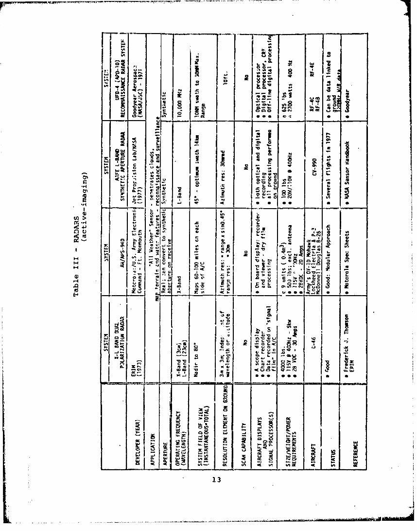
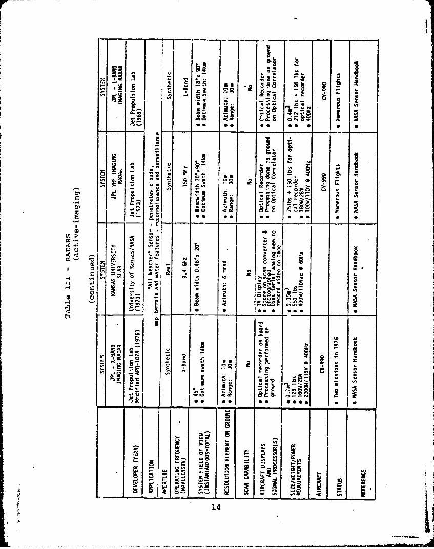
The most important characteristic of radar is its ability
to penetrate clouds (i.e., to be an "all-weather" sensor) and
map terrain and water features over a broad area of coverage.
The active microwave sensors are displayed in Table Ill. The
majority of these systems fall into the category of develop-
mental systems which have been built mainly to demonstrate
feasibility of a particular design. These systems have been
flown in support of numerous research programs and, in general,
have yi elded good to excellent results. The three production
systems available are 1) the AN/APS-94D (Motorola), 2) the
UPD-4 (APD-10) reconnaissance system (Goodyear), and 3) the
WX-50 (Westinghouse). These vary in weight from 140 lbs. for
the WX-50 system to 650 lbs. for the Goodyear system. The
highest resolution system is the APD-10, which is currently
installed in the Navy Marine Corps RF-4B reconnaissance air-
craft. This system is, however, fairly large and relatively
expensive. One must ascertain that the missions demanded
of MUSS require the use of the APD-10. Perhaps, a less
sophisticated ,:ystem wouild suffice.
12
la a
ocPd Z.
1. n z~ = .0 u
C9 a It %c. 00%-
41A j LAj .
-x 0. A-
C.41 Via 'a. w CD4n 0j
0 in fN
0
10 0 .
41 0 ~b-LiA LW L, : G
It 14. 4.L U9
in 1. 0 - 0 0. -C
iILL L' o o..
ix' v CL-~ WW .1 ; CI -0sA1 0cf)1z Vh
1i L.'a
3,c-
vi 4K 410, 4na4
~ z.-..,~ -xW 13
LU - 0. G
W= c
CL~ ~ ~ a02Cj0-
L. CcG3 c aC .
%A 0
2- un Cr C6 .aJn
CL. W 1 4 uCLg -0 41. 0c.o
0 0 00 00 0 @0 0
A IA _ _ _
Z~ 0 . lD.
0i %0 V
3. - ) 4 -' , o '0 '
.4.so as V
C...~~~ 8 _ ___
to W.19 . 1.0
0%- C: mE
CD 0 o 20vi 4-0' c, T( U - U
I-In6 4- 0n 41A 0 0 %n.u
- 510 NO L. --00 00 0 0e
cc - -j &A
I. La C,
cc-
-" -.mi of=
14
r!
- - 4) & --- 1- - - -
- --- -C- - 4-b
t,-
II
C I
""
In _,
*to
I- I S £In ~ 511 ~ *J
*1 I~ 4k; I
3b 4
L6 %J y
0* 0 000 0 OS
* a = = 15
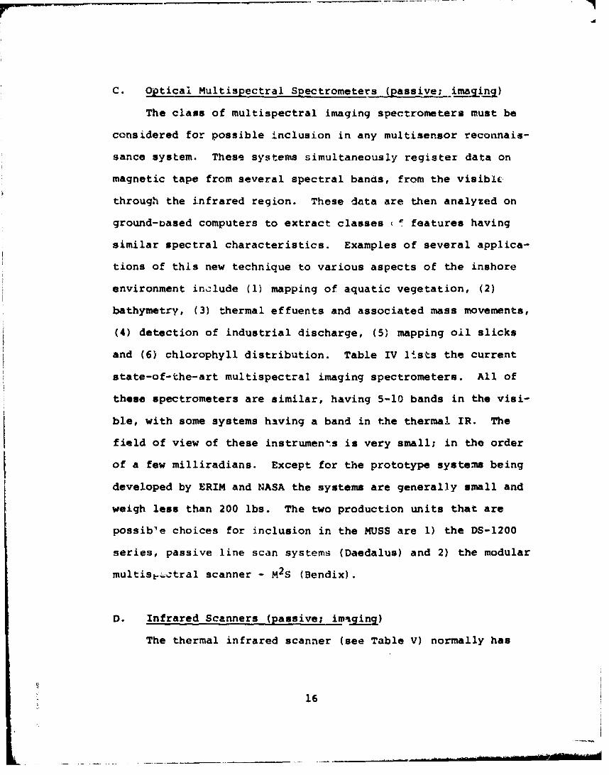
C. Optical Multispectral Spectrometers (passive; iMjiMf)
The class of multispectral imaging spectrometers must be
considered for possible inclusion in any multisensor reconnais-
sance system. These systems simultaneously register data on
magnetic tape from several spectral bands, from the visibic
through the infrared region. These data are then analyzed on
ground-oased computers to extract classes (I features having
similar spectral characteristics. Examples of several applica-
tions of this new technique to various aspects of the inshore
environment include (1) mapping of aquatic vegetation, (2)
bathymetry, (3) thermal effuents and associated mass movements,
(4) detection of industrial discharge, (5) mapping oil slicks
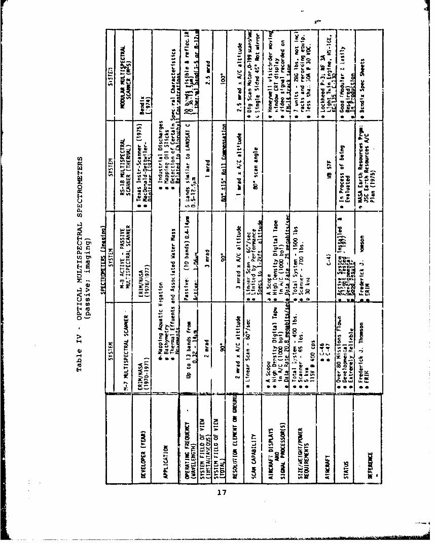
and (6) chlorophyll distribution. Table IV lists the current
state-of-the-art multispectral imaging spectrometers. All of
these spectrometers are similar, having 5-10 bands in the visi-
ble, with some systems having a band in the thermal IR. The
field of view of these instruments is very small; in the order
of a few milliradians. Except for the prototype systems being
developed by ERIM and NASA the systems are generally small and
weigh less than 200 lbs. The two production units that are
possible choices for inclusion in the MUSS are 1) the DS-1200
series, passive line scan systems (Daedalus) and 2) the modular
multisb.ctral scanner - M2 S (Bendix).
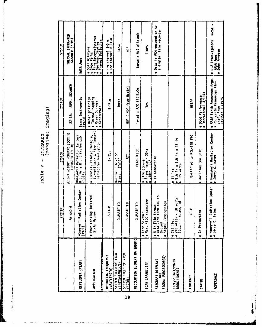
D. Infrared Scanners (passive; im4iq )
The thermal infrared scanner (see Table V) normally has
16
L)LW 0
10 ..0-0fl
f. a.ý
I.-.
On - r ? 0-2 2
*= dL ~ ~ ' I A W%
-w J- I. E
E-4 cc L #A
600 r-- 2'A k e C s
A S CIO "aim r)7.0 - L
E-4 19~
E-4 a5 *-*
-m
L9
L) a- u 0 IAi
z WJ gS fn C E
E-4 too ua 4jme z i C
~ '.SO C V U .0 co I ~ I ~ ~
CL il 4b em K . A I j
'aa
ID 55, 4.D 05 0U S
- L61 U - 6a C C
... ~). C, C
-Li 4iS nb
s'-. -. @17
%Aw..' '.r. 'r."k~-r''.
. . . . . .
0A0
.5 c
** 4- 8 Co.U
i& 4- 0
-OA $40 - .A 4 4
3t Qa:J - 6m .. CP
0 0 0 so @0
65 u-
75L -
*.9 i 0 'A
b. I o~0 ,;, 4 A a #U0 %
W , 4I c C 4 1 4
E4 4)1 K _ _- or_00
HL1 F0M. a-C
1, -. . m . " i,
.0 c 06
CL N .L t
E'c
-I.- m .. _
-- - -V =-ý - -D. 102 e uA, I. 8i - o- 18
r lo
'%A
6n ad. c
ata
* L
vi km -Z -
92 U *.Z a OX. wo
US CO% - S..
cI--~ q-1 coW
.2 -_
0)7
lz I- c
7- t.L. Oh k )-.F
r-.- %a % atoC -r 03 40 1 -
CL.. CS)
un~ %-- *-U-0. n,
cm 05. C3 ) fn.LJ L" -K
a~ L.)La""C Li
- 11 ) 6--: V~ ISL
A? 0i s0a 0. ~ s o.
oc- C, &a *j &A-%.. r3 atD.
-1 7. 3C
one channel in the infrared, located some place between 7-14,'m.
The NASA TIRS system has an additional channel to detect the
3-5um radiation. The systems are so designed that the forward
motion of the aircraft is 'used to generate an imaqe of the
tad.ation pattern. The I! sca.pners Are -seful in detecting and
mapping thermal anomalies in both the water and on land. The
most advanced prodtiction system appears to be the .AN AAD',
(Honeywell). The AN-AAD5 has been inst.alled in the Navy/Marine
Corps RF-4B reconnaissance aircraft. This system is relatively
light (283 lbs.) and should be considered as a candidate for
the MUSS.
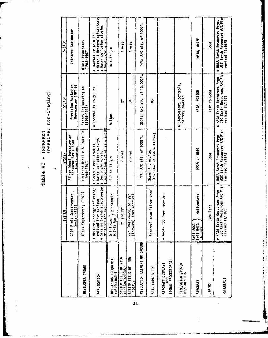
E. Infrared Radiometers/Spectro.mters (passive; non-imaging)
This category (shown in Table VIV is reserved for non-
Imaging radiometers that are used to detect thermal radiation
in the Epecti 1 region ranging betweer 6 and l4om. One system,
the S191 Field Spectrometer System (FSS) has a second channel
to detect radiation between 0.4-2.4um. In some cases, spectral
filter wheels are used to obtain radiation values for various
spectral bands. InfrareG ra4liometers have been used for various
ocean and meterological studies to detect.temperatures to +O.1*C.
These systems are generally small and could easily be used as
part of the MUSS. All systazms listed are possible candidates
for the MUSS.
F. Cameras
Four basic types of aeiial cameras are currently being
deployed. These cameras are listed under the following cateqories:
20
- a i0
*0~d on- 0~
*~~" M. 00)4 Aad %c S..
.4 4.5c U W 4ý 4-
,~~7 sool-~£
9..; 6141
4 0 tj4 0 4
+. =1#
C9 X. v - C%
-1 4. 4
0 C)9.
I- LM 4409
0 T1 a ) 01 0 :3 . 1aL*F r. 4.u141
411. T L 0 arl ; 1100 Lo CK .
A- %a L E .C: L. cc" 1U0
I,)n S.C 2.. .
diC in: . 4 iI m0u V0LL ' . % S"I r.. U
SC , . 4 S.0S. C. 4) 1-L0 .
4.~~~~. ImS 1 . 't)VS
..-. 3 CA 414 00@141 --- 141 =. I-
'-., ~ w ~ COOO S
C ~- U ICUU CD
- S.L~- 'aICE,.jb~I P.-V ~ 1.0f~* j. .~
('1 - w 4. w %
-~~_ w 0)1. 0 .
0 6 -1 X: 4I1 0
wn~ -, U- kA =A -c
21 L~
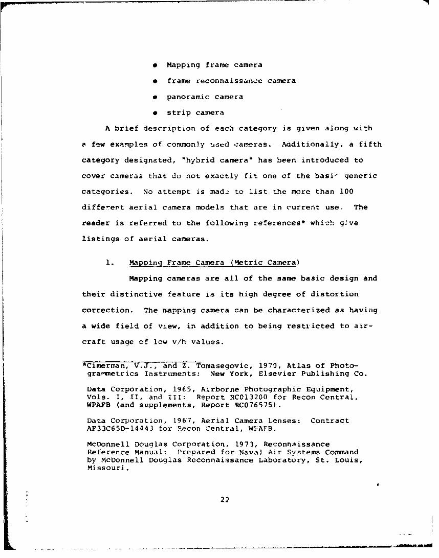
"* Mapping frame camera
"* frame reconnaissance camera
"* panoramic camera
"* strip camera
A brief description of each category is given along with
a few examples of commonly used cameras. Aaditionally, a fifth
category designated, "hybrid camera" has been introduced to
cover cameras that do not exactly fit one of the basi- generic
categories. No attempt is made to list the more than 100
different aerial camera models that are in current use. The
reader is referred to the following references* which give
listings of aerial cameras.
1. Mapping Frame Camera (Metric Camera)
Mapping cameras are all of the same basic design and
their distinctive feature is its high degree of distortion
correction. The niapping camera can be characterized as having
a wide field of view, in addition to being restricted to air-
craft usage of low v/h values.
;Cimerman, V.J., and Z. Tomasegovic, 1970, Atlas of Photo-gra-rnetrics Instruments: New York, Elsevier Publishing Co.
Data Corporation, 1965, Airborne Photographic Equipment,Vols. I, I1, and III: Report RC013200 for Recon Central,WPAFB (and supplements, Report RC076575).
Data Corporation, 1967, Aerial Camera Lenses: ContractAF33C65D-14443 for Recon Central, W'-AFB.
McDonnell Douglas Corporation, 1973, ReconnaissanceReference Manual: Prepared for Naval Air Systems Commandby McDonnell Douglas Reconnaissance Laboratory, St. Louis,Missouri.
22
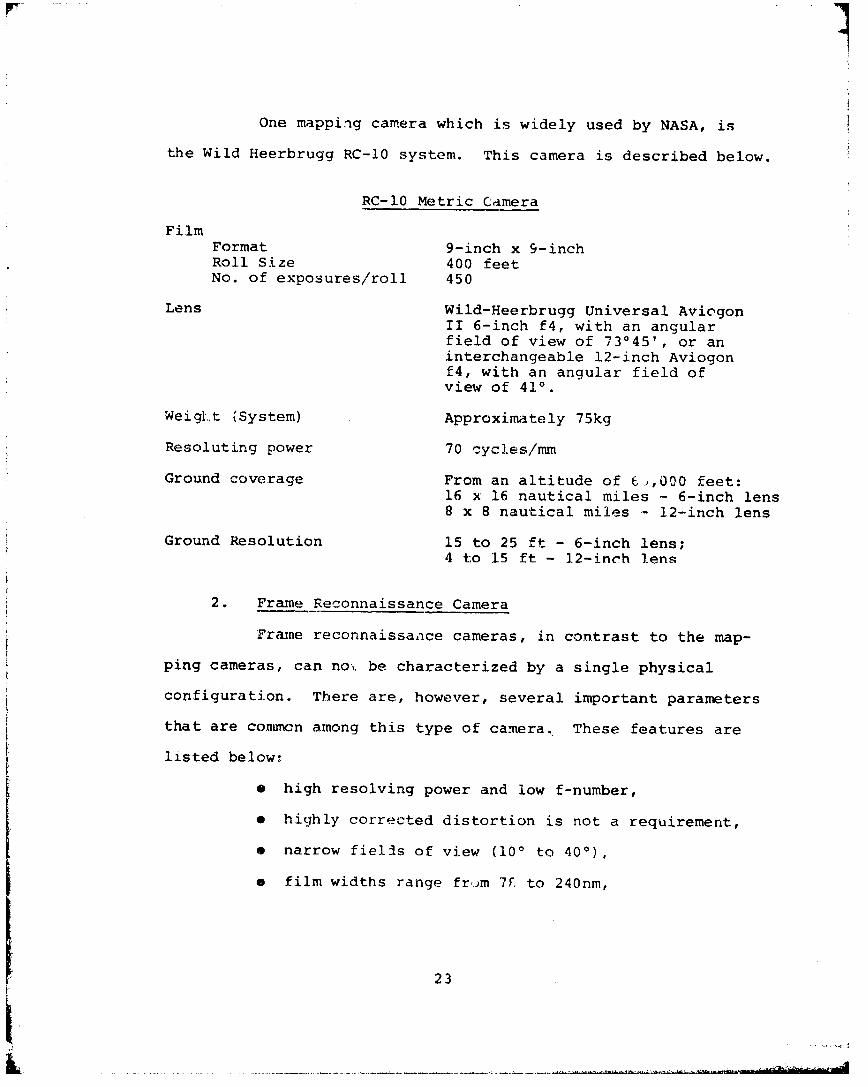
One mapping camera which is widely used by NASA, is
the Wild Heerbrugg RC-10 system. This camera is described below.
RC-10 Metric Camera
FilmFormat 9-inch x 9-inchRoll Size 400 feetNo. of exposures/roll 450
Lens Wild-Heerbrugg Universal AviogonII 6-inch f4, with an angularfield of view of 730451, or aninterchangeable 12-inch Aviogonf4, with an angular field ofview of 410.
Weiglt (System) Approximately 75kg
Resoluting power 70 cycles/mm
Ground coverage From an altitude of 6.,,000 feet:1.6 x 16 nautical miles - 6-inch lens8 x 8 nautical miles - 12-inch lens
Ground Resolution 15 to 25 ft - 6-inch lens;4 to 15 ft - 12-inch lens
2. Frame Reconnaissance Camera
Frame reconnaissance cameras, in contrast to the map-
ping cameras, can no,. be characterized by a single physical
configuration. There are, however, several important parameters
that are conmwcn among this type of camera. These features are
listed below:
* high resolving power and low f-number,
e highly corrected distortion is not a requirement,
• narrow fields of view (10' to 40*),
* film widths range frijm 7F to 240nm,
23
IL

* focal lengths range from a few cm to more than
a meter - common focal lengths are 6-inch.
12-inch and 18-inch,
* fccal plane shutters, and
* used in high-performance aircraft and high
v/h ratios.
One commonly used frame reconnaissance camera by the military
is the KS-87 built by Chicago-Aerial Industries. The KS-87
camera is currently installed in the Marine Corp's Marine
Tactical Reconnaissance Squadron Three (VMFP-3) RF-4B. Speci-
fications for the KS-87 camera are given below.
KS-87 Camera
FilmFojimat 4 1 ' /2 innh v A 1 inchRoll Size 500 feetNo. of exposures/roll 1300
Lens Dayphoto3,6,12or 18-inch focal lengthNhthoto
or 6 inch focal length
Weight Approximately 30-40kg
Ground coverage (lateral)Focal Length Lens Coverage3-inch 1.5 x A/C altitude6-inch 0.75 x A/C altitude12-inch 0.375 x A/C altitude18-inch 0.25 x A/C altitude
3. Panoramic Camera
The panoramic camera is characterized by its small
24
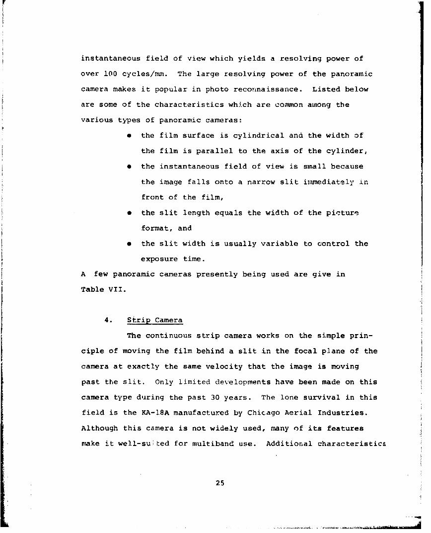
instantaneous field of view which yields a resolving power of
over 100 cycles/mm. The large resolving power of the panoramic
camera makes it popular in photo reconnaissance. Listed below
are some of the characteristics which are common among the
various types of panoramic cameras:
* the film surface is cylindrical and the width of
the film is parallel to the axis of the cylinder,
e the instantaneous field of view is small because
the image falls onto a narrow slit irimediately in
front of the film,
* the slit length equals the width of the picture
format, and
e the slit width is usually variable to control the
exposure time.
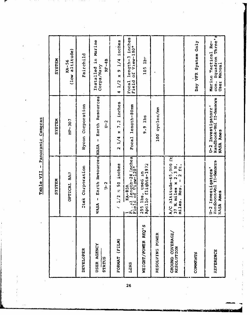
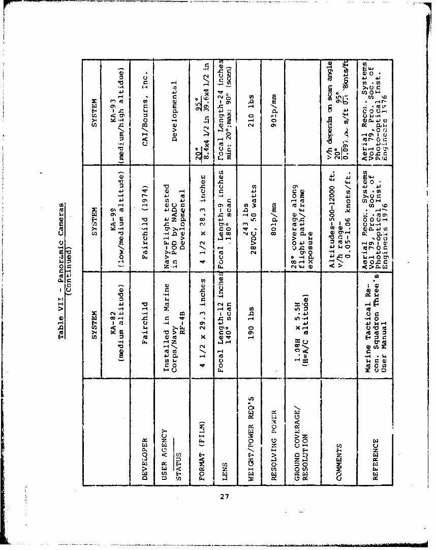
A few panoramic cameras presently being used are give in
Table VII.
4. Strip Camera
The continuous strip camera works on the simple prin-
ciple of moving the film behind a slit in the focal plane of the
camera at exactly the same velocity that the image is moving
past the slit. Only limited developments have been made on this
camera type during the past 30 years. The lone survival in this
field is the KA-18A manufactured by Chicago Aerial Industries.
Although this camera is not widely used, many of its features
make it well-su ted for multiband use. Additional characteristics
25
Pr r
02 (3)4J ., .41 0
-n $41 C 40 0 1
E -4 4. 4)-4 >1 3
>4 to ~ -4 ( ON r.~ -4 E- :4- 4 r-0- -
41 r 0 4N N '-40r-4 4J4 mJ H.4' *ý 4 :4
-4 0 A )kv t 0 00
0 0
$4 r-)
0 -40 to
>4 x 0
u C) > 0
r -4 0 rU '-' u>4 0 1c
4: (z4 L
OoI1-4r 0 ~ .,.4 0 4-t- C4J r-4 P
H -" 4J- P-1 '4 tA Nc~ 0-> -'4 N'41 4j
04 41 Ln ~41r4 tO~ *r..%4 t4 n) ty., :J 4 mU202
V -00 w I -
41 1 )4 .4 r4 ZE-4 0.~ Y( ) 4AO) 0- %~I
f-4 r:4 L04 mZ. Z 1
>4 4r
uJ H
Ci. IL 00
E- E- > ~ U
26
-4-n
41t 0 Hn
~~0 w -
ON Nr
54 0 P0 .i r4 C 3 10
> l 0i0
W' U 0 ;0 C) 00 r
00 > C4 a >20 N ..
::s - 4.) 0) N, 41 4)041 .0241 -'V a) '1'U 4J9 0 to n
-r4 r- 021 m 41 ~ 0 a'4-4
4J.i a% a) 1 -40 N ONNm C,, '-4 Q) U c ~ '-4 '-4 1 0 Un 0
CN ,4.- z.- =O w 4CD N 4 0 ý'.4' 0 0 mVz £o 41Z ie 4 l a0) X. 0n %0 W0 0)" u -
tr -W0 a Qj a) -4 -W Lo'4 .(A -. 0 0W x O 4 0 Q)04 0 0 4 W 61
N- >r O r-4 > 4 t 4 l. 14 -0 Uo
N,0 0 U a u C 4j~ t.s'o 0r0- rA >0 0 44 4F-4 0 t. l
09: H~~I4 i
'0 -H U *d
H jJ :3 w r
01 C 41 V -4 r4*'H E4 *qna I ou .04 1 4 -
0 a W~' H ) r4f'U 0u - - E '
c H W ~ C. tl04 -4r
W toN (D tox )qUr4'U,4 N4 '4Z-4 04a r4 Co'U.1
4.) tj -4 (a4r. I& 0 WW 000U
>4C U'- L
CDN -4 E-4 E-4 z
E- E-4 >a ~ In .
E-4 0.E =) 0 W
27
of the strip camera are:
* it has few moving parts, and these are continuous
rather than intermittant ar in other camera types,
"* very reliable,
"* an array of cameras can be readily synchronized by
driving them from a single shaft. The film rates
in each camera are therefore identical, and photo-
graphy of an area (with perfect boresighting) i3
simultaneous, and
"* the photography is continuous, so that no film is
wasted as in other forms of photography where a
safety margin of overlap is introduced.
5. Hvbr-id Cameras
a. Multiband Cameras
A number of different types of multiband cameras
have been built, however, they all operate on the same principal
- that of recording images of a scene simultaneously through a
variety of spectral filters. Excellent reviews of multiband
cameras are given in the following references* and will not be
repeated here. A list of some of the more widely used multiband
cameras is given below.
*Slater, P.N., 1972, Multiband Cameras; Photogram. Eng., vol38, p. 543-555.
*Manual of Remote Sensing, 1975, Robert G. Reeves (Editor),American Society of Photogrammetry, Falls Church, VA, vol I,p. 286-323.
28
* Nine lens (Itek)
* Model 10 (Spectral Data)
* Mark I (1 2 S)
* Aero I (Dot Products, Inc.)
e MPF (Itek)
These cameras all weigh in the order of 100 lbs. or less and
have shown to have good operational characteristics. Spectral
Data reports that U.S. Army tests comparing the Model 10 with
the KA-76 Frame Camera showed superior performance for target
detection using the multispectral camera.
b. Day/Night Laser Camera System
KA-98 Realtime reconnaissance system(Perkin-Elmer Corporation) *
Mu c. - mera A .e. Io__ped A a .. gallium
arsenide laser. The system was designed to be compatible with
the RF-4 and the RPV environment and mission profiles. The KA-98
system has been flight tested and imagery collected. The salient
characteristics of using gallium arsenide as the illuminator are:
"* spectral covertness (850nm:,
"* compactness,
"* efficiency, and
"* inherent contrast environment
"Toles, Marvin, KA-98 Realtime Reconnaissance System, Proceedings:SPIE, vol 101, Airborne Reconnaissance (1977), p. 6-9.
29
PrP
The KA-98 system consists of the gallium arsenide laser line
scanner, video tape recorder, a TV display console and a laser
diode film recording console. The TV display console consists
of two 2000 line TV monitors, one for the moving map display
and one for freeze frame viewing and enlargement, three scan
converter tubes, and associated electronics. The total weight
of the system is under 90 lbs. A similar type of system could
be built for mini-RPV's having a size of less than 0.2ft 3 and
weigh less than 10 lbs.
The KA-98 system has been flight tested in the
RF-4 aircraft and the BGM-34B RPV. During the RPV flight test,
the KA-98 was used in a realtime reconnaissance mode. Imagery
taken by the sensor was data linked to a ground TV display
console for realtime readout of the data.
c. ESSWACS - Solid State Camera System
(P.A Automated Systems/Air force)
A new type lightweight ( 64 lbs.) camera system
has been designed and constructed for realtime wide angle
reconnaissance from low flying, high performance aircraft*.
This system is composed of a multiple lens-linear CCD array
airborne sensor head, an air to ground data link; and a ground
based, dry silver film, laser beam recording system that pro-
duces hard copy imagery on the ground within 30 seconfts of
*Barton, G.T., Electronic Solid State Wide Agle Camera System -
ESSWACS, SPIE vol. 101 Airborne Reconnaissaace (1977), p.10-19.
30
r7
data acquisition. Flight tests of the ESSWACS system is sched-
uled for early 1978. The current silicon CCD sensors limit the
system to daytime, fair weather reconnaissance. Substitution
of an YR sensor or active illumination could extend the sensi-
tivity range, permitting nighttime and all weather cperatl.on.
The salient characteristics of the ESSWACS system are given in
Table VIII.
Table VIII - ESSWACS System Characteristics
Number of lenses 5Focal lengths 18mmt1), 53mm(2), 0llmm(2)Scanning mode Link_. Scen/Push BroomFOV 1400PhotoSensor
number-type 5-Fairchild CCD-121Helements/sersor 1724 (active)data rate 10.5 megasamples/sec
Video processing AGC, band limiting. ABLCVideo bandwidth
array sample rate 10.5 megasamples/secRecorder laser beam film recorderFilm width 4.55 inches activeFilm Dry silver (3M type 7869)Ground coverage 5210ft (from A/C altitude of 1000ft)Resolution l.Sft/lp central 80% @ 100,0001m mz
2.Oft/lp central 80% @ 3,0001m/m'
G. Active Laser Systems
The airborne laser sensor is the newest of the remote
sensors described in this report. La3er systems have been
built to measure various parameters of both the atmosphere,
the hydrosphere, including the following:
"* water depth
"* water temperature
31
e water salinity
* pollutants (water and atmosphere)
e wave heights
* atmospheric pressure and temperature
In spite of the research that has taken place in this field
during the past few years, such systems have not advanced to
the point where they can be considered off-the-shelf items. As
such they Frobably should not be considered as prime sensors for
inclusion into the MISS. The laser profilometer is the most
advanced type of laser system that has been built and tested
over the past few years. Wavelengths in the order of a few
centimeters have been measured with such laser systems.
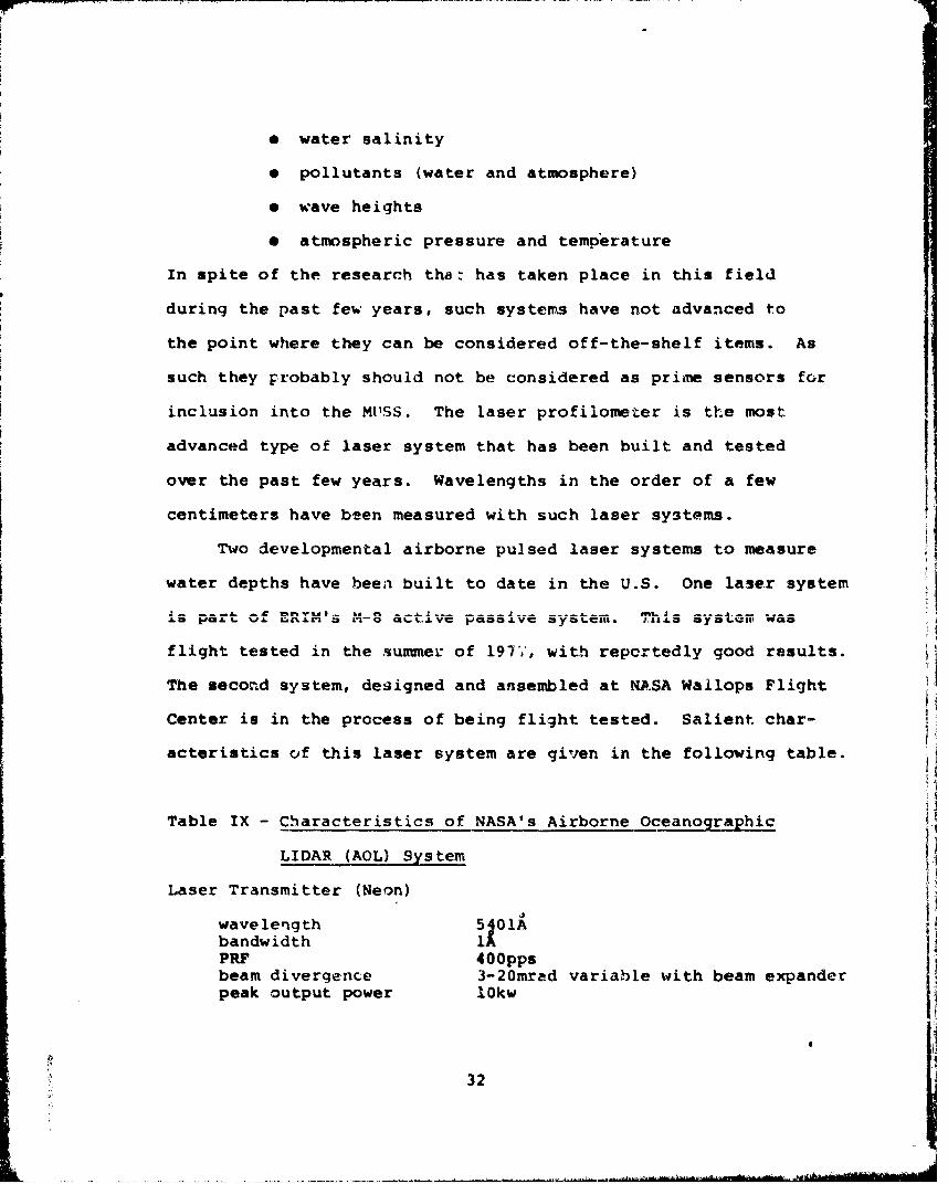
Two developmental airborne pulsed laser systems to measure
water depths have been built to date in the U.S. One laser system
L4 U& J partLr Uf nIM' acti.;.ve Passi.ve sys~tem. ThiSJ. asY*Dttii was
flight tested in the summer of 1977, with reportedly good results.
The second system, designed and ansembled at NASA Wallops Flight
Center is in the process of being flight tested. Salient char-
acteristics of this laser system are given in the following table.
Table IX - Characteristics of NASA's Airborne Oceanographic
LIDAR (AOL) System
Laser Transmitter (Neon)
wave length 5101Abandwidth 1PRF 400ppsbeam divergence 3-20mrad variable with beam expanderpeak output power lOkw
•,' 32iI
Si~ .
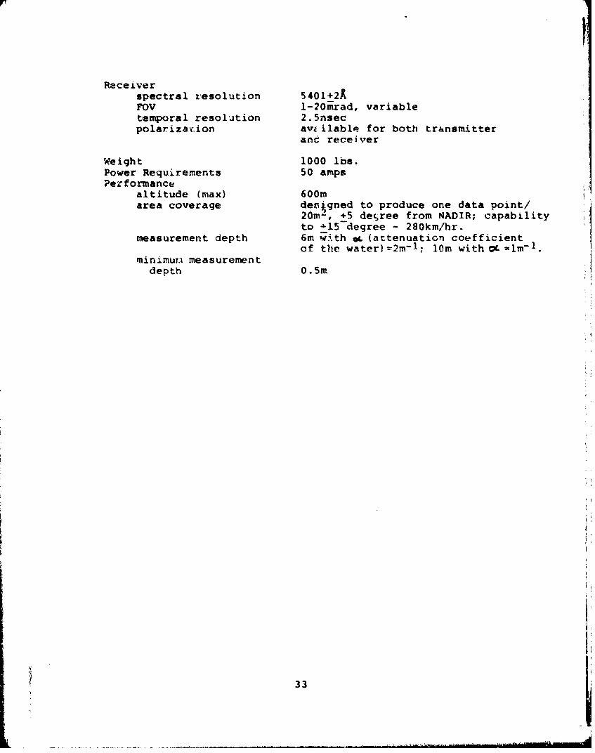
Receiverspectral resolution 5401+2AFOV -?20mrad, variabletemporal resolution 2.5nsecpolarizat ion av ilable for both transmitter
and receiver
Weight 1000 lbs.Power Requirements 50 ampsPerformance
altitude (max) 600marea coverage derigned to produce one data point/
20ml, +5 decree from NADIR; capabilityto '15 degree - 280km/hr.
measurement depth 6m w4ith oL (attenuation coefficientof the water)=2m- 1 ; 10m with OL'ls-1.
minimumi measurementdepth 0.5m.
33 h
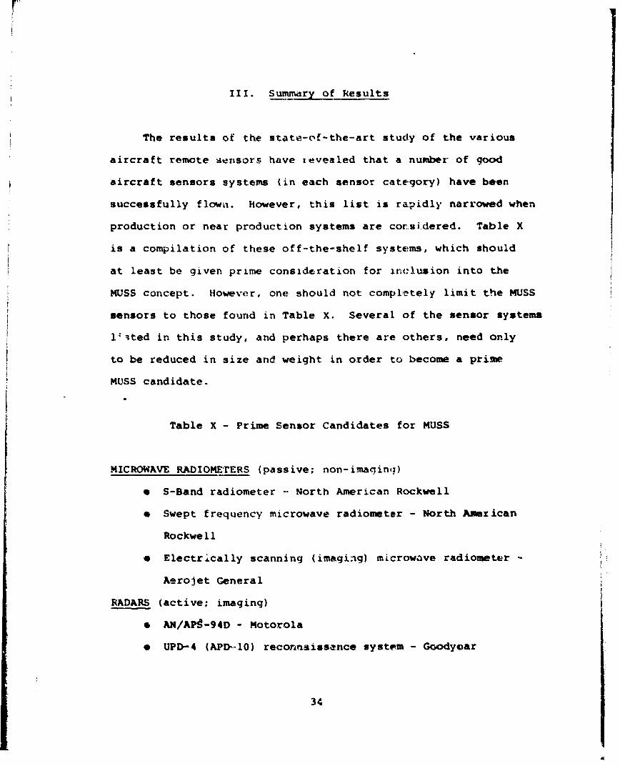
III. Summary of Results
The results of the state-of-the-art study of the various
aircraft remote sensors have revealed that a number of good
aircraft sensors systems (in each sensor category) have been
successfully flown. However, this list is rapidly narrowed when
production or near production systems are corsidered. Table X
is a compilation of these off-the-shelf systems, which should
at least be given prime consideration for inclusion into the
MUSS concept. However, one should not completely limit the MUSS
sensors to those found in Table X. Several of the sensor systems
1'ited in this study, and perhaps there are others, need only
to be reduced in size and weight in order to become a prime
MUSS candidate.
Table X - Prime Sensor Candidates for MUSS
MICROWAVE RADIOMETERS (passive; non-imaginq)
"* S-Band radiometer -- North American Rockwell
"* Swept frequency microwave radiometer - North American
Rockwell
"* Electrically scanning (imaging) microwave radiometer -
Aerojet General
RADARS (active; imaging)
"* AN/AP9-94D - Motorola
"* UPD-4 (APD-l0) reconnaissance system- Goodyear
34
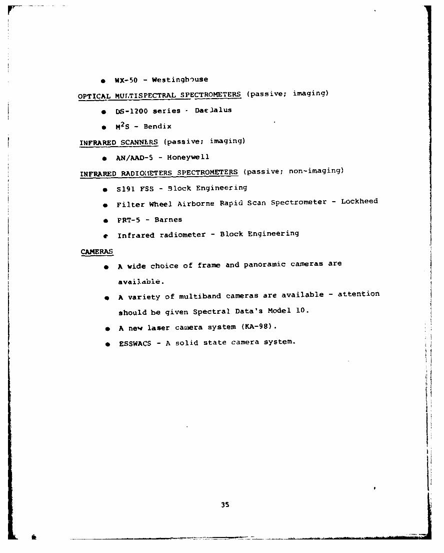
* WX-50 - Westinghouse
OPTICAL MULTISPECTRAL SPECTROMETERS (passive; imaging)
o DS-1200 series - Daelalus
0 M2 S - Bendix
INFRARED SCANNLRS (passive; imaging)
e AN/AAD-5 - Honeywell
INFRARED RADIOM1ETERS SPECTROMETERS (passive; non-imaging)
* S191 FSS - Block Engineering
* Filter Wheel Airborne Rapid Scan Spectrometer - Lockheed
e PRT-5 - Barnes
e Infrared radiometer - Block Engineering
CAMERAS
* A wide choice of frame and panoramic cameras are
availabDle.
e A variety of multiband cameras are available - attention
should be given Spectral Data's Model 10.
* A ne'i laser camera system (KA-98).
* ESSWACS - A solid state camera system.
35

IV. CONCLUSIONS/RECOMMENDATIONS
A number of various types of sensors were listed in section
III as prime sensors to be considered for inclusion into the
MUSS. A number of reasons went into this final selection, but
in general these systems are the most advanced, relatively small,
both in size and weight, and require minimum power to operate.
These systems have been operated with good success and the
majority are in production.
Substantial information must be supplied by the user
agency (Navy/Marine Corps) prior to arriving at a final set of
reccmmendations for the MUSS sensors. Some of the information
which must be supplied includes.
adeti •pecifications of the various missions
required for MUSS,
o ascertain the environmental parameters that are
deemed requirements - along with associated measure-
ments such as frequency, tolerance, and coverage.
This detailed assessment is required to determine the altitude
and type of aircraft. For instance, it tuay be determined that
a single MUSS configuration will not sufffice. If such is
the case, it may be possible to consider a modular approach,
in which specific sensors for a certain type of mission will
be chosen - while one or more of the sensors are replaced
for another type mission.
The type of aircraft to be deployed is the driving force
36
iL
in designing the MUSS since the aircraft determines the avail-
able sensor weight, the altitude and the area coverage of the
system. Some of the sensors identified in this report have
either been flown successfully on RPV's or could be fairly
easily adaptable to the RPV environment. The RPV's should
therefore be considered as a possible MUSS platform.
Two othc-- considerations that play an important role in
arriving at a final set of reccmmendations for the MUSS are
1) onboard realtime displays and operator interaction, and
2) telemetry and data link requirements.
Data link requirements evolve from either of two needs.
The first need is that of the tactical commander for near
realtime update of highly perishable information relayed from
the airborne reconnaissance capability to his ground command
post. The commander may also wish to re-direct the mission
flight plan or re-target an objective based on needs for
relevant data or complementary information.
The second need deriives when a beneficial trade-off can
be made for tactical aircraft configurations between large
onboard processors and minimal preprocessors with RF link
to ground processing and display equipment.
The output data rate for the sensor systems which have
been described varies ( ;er a considerable range depending
on the information density and the required readout rate.
"..•e unique imaging sensor may output data at millions
:,i bits per second. The transmittal of such high data rates
37
in realtime would require substantial bandwidth in the data
link channel whereas selected data or frames could be relayed
ever a longer period in a narrower bandwidth channel and complete
data could be recorded for detailed analysis upon landing.
Other types of sensors, e.g., laser depth finders, provide
relatively few data points with simple information.
The multiplicity of these sensors, their type, the scanning
or acquisition data rate, the internally processed output data
forrat and rate, and the required update rate required by ie
ground terminal are all basic factors which are to be coordin-
ated into a compatible data link.
The following recommendations (tasks) are, therefore,
made with regard to completing the concept phase of MUSS.
1. Ascertain the exact reccnnaissance mission(s) for a
MUSS system, including the parameters to be measured,
their tolerance and coverage (temporal and spatial),
II. determine the A/C platforms that will be deployed
in a MUSS system,
III. determine the exact remote sensors to be assembled
to form a MUSS - determine alternative systems if
more than one type of mission and/or one type plat-
form are deemed practical,
IV. the final MUSS sensors will be based on the results
of both phase I (this report) and the above mentioned
task4 (I-III),
V'. detail investigations of the A/C displays and telemetry
requiremerts of the MUSS.
38
Unclassified
DOCUMENT CONTROL DATA. R & D(Securtytp classification of fillce. brdy of abstract oand indexing annotation niujtt bte nto,~d whon he overall report ise el.r'811fjd)
I. ORIGINATING ACTIVITY (Corporate autIhor) Za. REPOAT SECURITY CLASSIF~ICATION
Applied Science Technology, Inc.ýloll Arlington Blvd... Suite 319 a.atu
rl~ington, VA 22209
Multi-Sensor System (MUSS) for Airborne Surveillance of Inshore Waters#
4,0111ISCRIPTIVIC WNTES (Type of report and inclus date&)
$a. ORIGINATOR'S REP014r NUMSERIS)
~i 4-6Cl d2 chnical Report N&,A T-7701
NR 387-090 Rd.
10~. DISTRINUTION STATEMENT
Approved for public release; distributioyr unlimited
11. SUPPLEMENTARY NOTES I, SPONSORING MILITARY ACTIVITY
Geography ProgramusOffice of Naval Research
_______________________________ Arlington, Virgni 221IS, ASISFAACT
Dana. were assembled and listed in this report on state-of-the-~art air-craft sensorswhich could be integrated to form a Multi-Sensor System (MUSS) for surveillance ofinshore waters. The fol~lowing sensor categories are included: radars (active,
camr~sandactve ase sytem. Te MSS igh bereqire toperformtefolowig mssins:rl)colec daa o prvioisl unharedarers;k&2) collect
mustbe easredby he MSS nclde:lenth, idt, gadintsurf and tidal
yi ed iforatin o th tye o seimet ad taffcablit ofthe rearshovo zonein addition to locatinp obstacles in the surf zon'e and mapping the ground ..over. F
DD VJM 473 (PAGE 1) ~_ _ _ _ _ _ _ _
S/N 10ý-507-801Secutrity Clessification

Security Cla3sificatlon
14 LINK A LINK C LINK C
Ko WO[R5wTOLC WT MOLC WY NOLE WT
Remote SensingAircraft SensorsInshore SurveillanceBeach Reconnaissance
4Q
--DD TPoEM147/3 JI'ACk) _ _ _ _ _ _ _ _
U'nclassified(PAGE 2) Security Clessflcation
Recommended


![Indian Navy’s Inshore Patrol Vessels · Indian Navy’s Inshore Patrol Vessels 1 Indian Navy’s Inshore Patrol Vessels [v1.0][16.Jun.2012][© Aditya Gupta] In the naval scheme](https://img.pdfslide.us/doc/110x75/5e89d0576f98607fc62794b1/indian-navyas-inshore-patrol-vessels-indian-navyas-inshore-patrol-vessels-1.jpg)