JOURNAL OF RESOURCE
MANAGEMENT AND TECHNOLOGY
ISSN NO: 0745-6999
Vol12, Issue3, 2021
Page No:223
FOPID Based Coordinated Control Strategies for DG units in an Unbalanced Micro-grid
1B Janardhana Reddy, UG Student, Department of EEE, Pragati Engineering college, Surampalem
2K Satyanandham, UG Student, Department of EEE, Pragati Engineering college, Surampalem
3Bakki Chandra Vamsi, UG Student, Department of EEE, Pragati Engineering college, Surampalem
4Chitikina Gowrinath, UG Student, Department of EEE, Pragati Engineering college, Surampalem
5Katta Manoj Kumar, UG Student, Department of EEE, Pragati Engineering college, Surampalem
Abstract— This paper presents the positive
sequence, negative sequence and zero
sequence voltage and current control
schemes in dq-frame for the Voltage Source
Converter (VSC) based Distributed
Generation (DG) units in order to
compensate for voltage unbalance in a
microgrid. The objective of these schemes is
to control the positive, negative and zero
sequence components (separately and
independently) of the voltage at the Point of
Common Coupling (PCC) and the VSC
currents to their respective reference
commands. Dynamically varying limits have
been proposed for the positive and negative
sequence references for the current control
schemes in order to protect the VSC from
overloading (under unbalanced conditions)
and unsymmetrical faults. The active power
control, frequency control and the reactive
power–voltage droop control schemes
decide the references of the positive
sequence voltage control scheme in order to
fulfill the objective of using the same
control schemes for the grid connected and
the islanded modes of operation of the
microgrid, thereby eliminating the need for
islanding detection. The performance of the
various control schemes employed for
controlling the VSC based DG unit have
been tested on two identical VSC based DG
units feeding power to the IEEE 34 node
distribution network implemented in
PSCAD/EMTDC.
I. INTRODUCTION
MOST of the renewable energy sources (like
PV, FC, etc) generate DC power, and most
of the storage systems (like Battery, Super-
capacitor, etc) handle energy in the form of
DC. These energy sources and storage
systems need to be interfaced with the AC
Microgrid through Voltage Source
Converters (VSC). AC Microgrids are
usually low voltage distribution networks
with Distributed Generation (DG) units
supplying power to the local loads [1]
(which are inherently unbalanced). Thus the
VSCs will be supplying unbalanced currents
for most of the time and therefore a proper
control scheme needs to be chosen for the
VSC so that the performance of the VSC
doesn’t get drastically affected. Another
challenge involving the control of VSCs is
in the control schemes for the Grid
Connected and the Islanded modes of
operation. When the microgrid is in the Grid
connected mode of operation, the voltage
and frequency of the microgrid will be
imposed by the Main Grid, but when the
microgrid is in the Standalone or Islanded
mode of operation, the VSCs need to set the
voltage and frequency of the microgrid.
Therefore researchers initially proposed the
idea of separate control schemes for VSCs
operating in the Grid connected and the

JOURNAL OF RESOURCE
MANAGEMENT AND TECHNOLOGY
ISSN NO: 0745-6999
Vol12, Issue3, 2021
Page No:224
islanded modes of operation [2]. The same
concept was extended in [3] in order to deal
with unbalanced loads. However, a
transition from the grid connected mode to
the islanded mode of operation and vice
versa will result in forced switching between
two sets of controllers, which will clearly
indicate the need for a fast and a reliable
islanding detection. Islanding detection
continues to be an area of research as there
is no method that is absolutely conclusive.
Therefore researchers began to propose the
idea of a unified control scheme which will
be valid for both the Grid connected
structure proposed in [4] aims to control the
VSC as a synchronous machine with an
assumed virtual inertia constant (H) and a
virtual damping constant (KD). However
grid faults will cause damage to the VSC
switches due to over currents. Reference [5]
expanded upon the ideas presented in [6]
and [7] and proposed a control scheme that
is valid for both the grid connected and the
islanded modes of operation thereby
eliminating the need for islanding detection.
However the Grid connected and the
Islanded modes of operation have been
considered separately and the positive and
negative sequence components of the
voltages and currents in the results have not
been explicitly presented. The control
schemes proposed in [6], [7] and [11] are
robust as long as the system is balanced, but
under unbalanced loading conditions, the
voltage at the Point of Common Coupling
(PCC) becomes severely unbalanced and
distorted; thereby the performance of the
VSC gets deteriorated. In order to overcome
this problem, in references [12] – [14]
suitable modifications have been proposed
to the control schemes presented in [6], [7]
and [11] so that the voltage at the PCC is
balanced irrespective of the unbalance in the
load. However the presence of Zero
Sequence Components have not been
considered due to the fact that delta
connected transformer windings were
considered in [12] and delta connected loads
were considered in [13]. While in [14], the
researchers have used separate control
schemes for the grid connected and the
islanded modes of operation. In references
[15], [16], [17], [18], [25], [26], [27] and
[29] voltage unbalance has been
compensated in __-frame (zero sequence
components have been neglected, except in
[25], [26] and have been controlled as
sinusoidal signals), but deciding the limits
for the references of the current control
loops will be a major problem due to the fact
that the signals fed to the controllers are
sinusoidal. The use of a saturation block will
make the reference currents non-sinusoidal
(if the VSC is overloaded) especially during
fault conditions. Therefore the aim of this
paper is to fulfill the following objectives:
To maintain the Line to Ground
Voltages at the PCC of the VSCs
balanced, irrespective of the
unbalance in the load in the
microgrid.
To limit fault currents (especially
unsymmetrical faults) in order to
protect the VSC switches from
getting damaged.
The control scheme should be the
same for both the grid connected as
well as the islanded modes of
operation
There by eliminating the need for
knowing the prevailing mode of
operation of the microgrid.
Zero sequence VSC current and PCC
Voltage control schemes have been
proposed in this paper and have been
implemented along with the improved
versions of the positive and negative
sequence VSC current and PCC Voltage
control schemes (with respect to the control
structures presented in [13]). The
improvements those have been made in the
JOURNAL OF RESOURCE
MANAGEMENT AND TECHNOLOGY
ISSN NO: 0745-6999
Vol12, Issue3, 2021
Page No:225
positive and the negative sequence VSC
current and PCC Voltage control schemes
are, that the variation in frequency has been
considered in the feed forward terms and
dynamically varying limits have been
considered in both the PCC voltage and the
VSC current control structures thereby
resulting in an improved transient
performance. Therefore the positive,
negative and zero sequence components of
the VSC current and the PCC Voltage will
be controlled separately and independently.
Dynamically varying limits have been
proposed for the positive and negative
sequence references of the VSC current
control schemes in order to protect the VSC
from overloading under unbalanced
conditions and unsymmetrical faults. The
Active Power Control, Frequency Control
and the Reactive Power–Voltage droop
control schemes presented in [5] will decide
the references for the positive sequence
voltage control scheme, while the references
of the Negative and Zero Sequence PCC
Voltage control schemes have been set at ‘0’
in order to fulfill the objective of
maintaining the voltage at the PCC balanced
at all times. The effectiveness of the control
schemes have been tested on two VSC based
DG units (shown in Fig. 1(a)) feeding power
to the modified IEEE 34 node distribution
network (shown in Fig. 1(b)). The rest of the
paper is organized as follows. In Section II,
a description of a VSC based DG unit with
PV array and the Battery Energy Storage
System (BESS) has been presented. In
Section III, the various control schemes for
controlling the VSC and the Buck-Boost
converters have been presented. In Section
IV, the simulation results have been
presented in order to demonstrate the
effectiveness of the control schemes
presented in this paper. Section V concludes
the paper.
II. SYSTEM DESCRIPTION
Fig. 1(a) shows the schematic diagram of a
VSC based DG unit. A three phase three
level Neutral Point Clamped (NPC)
converter acts as a VSC and is connected to
the microgrid through a three phase LC filter
and a three phase coupling transformer
(Both the primary and secondary windings
of the coupling transformer are Y-connected
and the neutral point is grounded). Two
BESS banks (represented by the Thevenin’s
equivalent model which is slightly different
from the model presented in [19]) are
connected in parallel to the DC link
capacitors (C1 and C2). Two identical PV
arrays (represented by the Norton’s
equivalent model [20], [21]) are connected
to the DC link capacitors (C1 and C2)
through two Buck boost converters. The
Buck-boost converters operate in such a
manner that the PV arrays always deliver
power at the Maximum Power Point (MPP).
The VSC supplies power to the microgrid
according to the reference command (when
the microgrid is in the grid connected mode
of operation) or according to the load
demand (when the microgrid is in the
islanded mode of operation). The BESS
banks take care of
the mismatch between the power generated
by the PV array and the power supplied by
the VSC (The BESS banks will either get
charged or discharged depending on the
direction of flow of current through the
BESS banks). Two identical VSC based DG
units are connected at nodes ‘850’ and ‘832’
of the modified IEEE 34 node distribution
network shown in Fig. 1(b). Fig. 1(c) shows
the representation of the improved version
of the SRF–PLL [9], [10] and the objective
of this PLL is to synchronize the dq-frame
with the positive sequence component of the
voltage at the PCC (that is the converter side
of the coupling transformer as shown in Fig.
1(a)).

JOURNAL OF RESOURCE
MANAGEMENT AND TECHNOLOGY
ISSN NO: 0745-6999
Vol12, Issue3, 2021
Page No:226
III. CONTROL STRATEGY
This paper mainly focuses on improvement
of non-linear power damping controller to
integrate VSC’s to weak grids. Fig.1 shows
the grid connected VSC supplying a local
load. It has linear power-damping/
synchronizing controller and non-linear
power damping controller. Fig.3 shows the
linear control structure. Fig.4 shows non-
linear control structure.
Also, it has a voltage amplitude controller
which provides specific control depending
on type of bus. It provides different control
strategy for output voltage to PV and PQ
bus. It is shown in Fig.6. The angle and
frequency loops provide synchronizing and
damping power components for the VSC to
track frequency and angle deviations of the
grid and automatically synchronizes with
grid.
Depending on the frequency error only the
reference of the load angle is found and the
real power reference is obtained as the
function of load angle error. The reference
frequency (ωset) in the frequency loop is set
equal to the grid frequency and the VSC
gives the reference power (Pset) in steady
state conditions. The transferred real power
is given by
𝑃 =𝐸
𝑅2+𝑋2(𝑋𝑉𝐿𝑠𝑖𝑛𝛿 + 𝑅(𝐸 − 𝑉𝐿𝑐𝑜𝑠𝛿)).
(1)
SCR defines the strength of the connecting
line as
SCR = 𝑠ℎ𝑜𝑟𝑡 𝑐𝑖𝑟𝑐𝑢𝑖𝑡 𝑐𝑎𝑝𝑎𝑐𝑖𝑡𝑦
𝑟𝑎𝑡𝑒𝑑 𝑐𝑎𝑝𝑎𝑐𝑖𝑡𝑦 (2)
Where short circuit capacity(Ssc) is given by
𝑆𝑆𝐶 =𝐸0
2
𝑍 (3)
Where, Z is the circuit equivalent Thevenin
impedance. This implies that the weaker the
grid, the lower the power transfer capacity
of the line. In aweak grid with, the
theoretical maximum power transfer
capacity is 1.0 p.u.
The power-damping control law for a VSC
is proposed as
𝑑𝛥𝜔
𝑑𝑡 =-KpKf Kd (ω-ωset) - KpKf δ - Kp (P-
Pset). (4)
The damping and synchronization power
components are
Damping power = 𝛥 Pdamp = - Kf Kd 𝛥𝛚. (5)
Synchronizing power = 𝛥 Psynch = - Kd 𝛥δ.
(6)
It is important to take into account that the
VSC’s frequency and angle are internally
available; therefore, there is no need for a
PLL in steady-state operation and several
transient conditions.
Fig.3. Linear control scheme.

JOURNAL OF RESOURCE
MANAGEMENT AND TECHNOLOGY
ISSN NO: 0745-6999
Vol12, Issue3, 2021
Page No:227
Fig.4. Non-linear supplementary
control structure.
IV. SYSTEM MODELING
To evaluate system dynamic performance in
a weak grid, a small-signal stability analysis
of a grid-connected VSC is presented in this
section. The three-phase power system
involves a converter and its controller, RL
filter, connecting line and infinite grid.
Assuming an ideal VSC, the VSC local
voltage is equal to the controller command,
thus it is possible to model the VSC and
PWM block by an average voltage
approach. The system parameters are given
in Table I. The augmented model of the
VSC and its controller can be developed as
follows. First, the load angle dynamic
equation is given by
𝛥�̇� = 𝛥𝑤 (7)
The frequency dynamic equation is
expressed by (4) where is given by
𝛥𝑃 =𝜕𝑃
𝜕𝛿𝛥𝛿 +
𝜕𝑃
𝜕𝐸𝐹𝛥𝐸𝐹 (8)
Fig.5. Control topologies for output voltage
control. (a) P-V bus control. (b) P-Q bus
control strategy.
The voltage loop dynamic equation is given
by
𝛥�̇� = −𝑤𝑣̇ 𝛥𝐸 + 𝑤𝑣𝛥𝑣 − 𝑤𝑣𝐾𝑣 𝛥𝐸𝐹 (9)
𝛥�̇� = −𝐾𝑣𝑖𝛥𝐸𝐹 (10)
Where 𝑣 is the output of the integrator 𝐾𝑣𝑖 ,
and 𝐸𝐹 is the filter voltage amplitude
expressed by
𝛥𝐸𝐹 =𝐸𝐹𝑑0𝛥𝐸𝐹𝑑+𝐸𝐹𝑞0𝛥𝐸𝐹𝑞
𝐸𝐹0𝜋𝑟2 (11)
𝛥𝐸𝐹𝑑 = 𝐿𝑐𝑑𝛥𝑖𝑑
𝑑𝑡+ 𝑅𝑐𝛥𝑖𝑑 − 𝑤0𝐿𝑐𝛥𝑖𝑞 (12)
JOURNAL OF RESOURCE
MANAGEMENT AND TECHNOLOGY
ISSN NO: 0745-6999
Vol12, Issue3, 2021
Page No:228
𝛥𝐸𝐹𝑞 = 𝐿𝑐𝑑𝛥𝑖𝑞
𝑑𝑡+ 𝑅𝑐𝛥𝑖𝑑 + 𝑤0𝐿𝑐𝛥𝑖𝑑 (13)
The currents dynamics in the dq reference-
frame are given by
𝑑𝛥𝑖𝑑
𝑑𝑡=
1
𝐿(−𝐸0𝑠𝑖𝑛𝛿0𝛥𝛿 + 𝛥𝐸 𝑐𝑜𝑠𝛿0
− 𝑅 𝛥𝑖𝑑 + 𝑤0𝐿𝑐𝛥𝑖𝑞) (14)
𝑑𝛥𝑖𝑞
𝑑𝑡=
1
𝐿(−𝐸0𝑐𝑜𝑠𝛿0𝛥𝛿 + 𝛥𝐸 𝑠𝑖𝑛𝛿0
− 𝑅 𝛥𝑖𝑞 − 𝑤0𝐿𝑐𝛥𝑖𝑑) (15)
The overall system model is
𝑥1̇ = 𝑥2 (16)
𝑥2̇ = 𝑎1𝑥1 + 𝑎2𝑥2 + 𝑎3𝑥3 (17)
𝑥3̇ = 𝑢𝑓 + 𝐸𝑉𝐿
𝑋𝑥2 𝑐𝑜𝑠𝑥1 − 𝑤𝑣𝑥3 (18)
Where 𝑎1= -Kp Kd , 𝑎2 = -KpKf Kd and 𝑎3 = -
Kp , and
[𝑥1, 𝑥2 , 𝑥3] = [𝛥δ , 𝛥𝛚 , 𝛥P] . 𝑢𝑓 is defined
as
𝑢𝑓 = (u𝛚c VL sin 𝑥1 )/X , where u is the
control input.
The control objective is to ensure the
convergence of the error ei = xi - xiref to zero.
The first step is to stabilize δ, thus the
Lyapunov function
𝑉1 =1
2𝑥1
2 (19)
is defined and the reference of frequency
deviation value and 𝑉1̇ are given by
𝑥2𝑟𝑒𝑓 = −𝐾1𝑥1 𝐾1 > 0 (20)
𝑉1̇ = −𝐾1𝑥12 + 𝑥1𝑒2. (21)
In the next step, the Lyapunov function is
defined as V2 = V1 + 1/2𝑒22 and 𝑥3𝑟𝑒𝑓 is
chosen to stabilize V1 and V2
𝑥3𝑟𝑒𝑓 = 𝑐1𝑥1 + 𝑐2𝑒2 (22)
Where 𝐶1 =(1−𝑘1(−𝑎2+𝑘1)+𝑎1)
𝑎3 (23)
𝐶2 = −(𝑘1+𝑘2+𝑎2)
𝑎3, 𝑘2 > 0 (24)
Finally, by defining
𝑉3 = 𝑉2 +1
2𝑒3
2 (25)
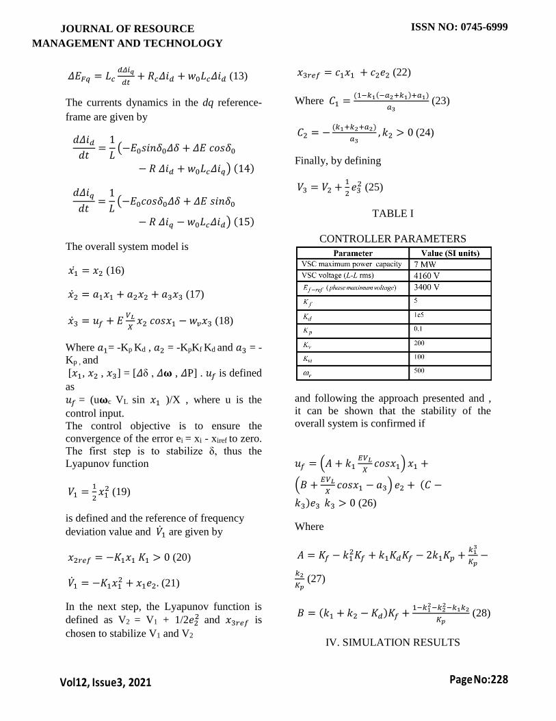
TABLE I
CONTROLLER PARAMETERS
and following the approach presented and ,
it can be shown that the stability of the
overall system is confirmed if
𝑢𝑓 = (𝐴 + 𝑘1𝐸𝑉𝐿
𝑋𝑐𝑜𝑠𝑥1) 𝑥1 +
(𝐵 +𝐸𝑉𝐿
𝑋𝑐𝑜𝑠𝑥1 − 𝑎3) 𝑒2 + (𝐶 −
𝑘3)𝑒3 𝑘3 > 0 (26)
Where
𝐴 = 𝐾𝑓 − 𝑘12𝐾𝑓 + 𝑘1𝐾𝑑𝐾𝑓 − 2𝑘1𝐾𝑝 +
𝑘13
𝐾𝑝−
𝑘2
𝐾𝑝 (27)
𝐵 = (𝑘1 + 𝑘2 − 𝐾𝑑)𝐾𝑓 +1−𝑘1
2−𝑘22−𝑘1𝑘2
𝐾𝑝 (28)
IV. SIMULATION RESULTS

JOURNAL OF RESOURCE
MANAGEMENT AND TECHNOLOGY
ISSN NO: 0745-6999
Vol12, Issue3, 2021
Page No:229
The modified IEEE 34 node distribution
network (which is acting as a microgrid)
shown in Fig. 1(b) with two identical VSC
based DG units feeding power to the
network has been implemented in
MATLAB/SIMULINK. The modification
that has been done is that the voltage
regulators originally present in the network
[8] have been removed for the purpose of
studying the capability of the VSCs in
improving the voltage profile of the feeder
in the absence of voltage regulators. The
data of the IEEE 34 node distribution
network is available in [8] and the
parameters of the DG units and the
compensators have been mentioned in
Tables I and II respectively. The rated
capacity of the PV array in each DG unit is
2300 kW at STC, and the reference
command for the Active Power Control loop
of both the VSCs is 1150 kW. A. Transition
from the Grid Connected mode of Operation
to the Islanded mode of Operation: The
microgrid was operating in the Grid
Connected mode of operation. The PV
arrays of both the DG units were operating
at the Maximum Power Point (MPP) at STC
and were generating 2300 kW each. Both
the VSCs were supplying 1150 kW to the
microgrid (VSC-1 was supplying around
200 kVAR and VSC-2 was supplying
around 320 kVAR to the microgrid). The
microgrid was supplying around 450 kW
and 150 kVAR to the main grid as shown in
Fig. 5b (due to the fact that the power
supplied by the VSCs to the microgrid is
more than the power consumed by the load
in the microgrid). Suddenly at t=0.75s, the
circuit breaker ‘BRK’ has been opened.
Based on the results presented in Fig. 5a, 5b
and 5c, it is clear that the microgrid is no
longer synchronized with
(a) Mode Selection from Grid to
Islanding Condition
(a) Mode Selection from Grid to
Islanding Condition
JOURNAL OF RESOURCE
MANAGEMENT AND TECHNOLOGY
ISSN NO: 0745-6999
Vol12, Issue3, 2021
Page No:230
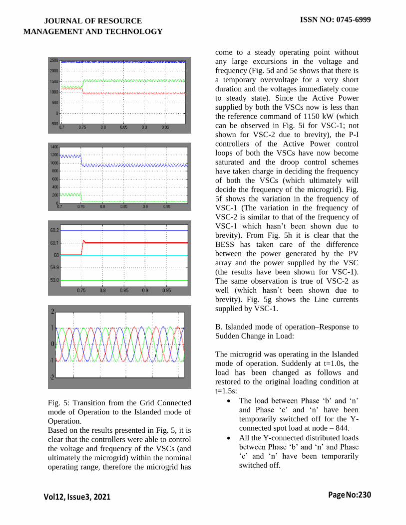
Fig. 5: Transition from the Grid Connected
mode of Operation to the Islanded mode of
Operation.
Based on the results presented in Fig. 5, it is
clear that the controllers were able to control
the voltage and frequency of the VSCs (and
ultimately the microgrid) within the nominal
operating range, therefore the microgrid has
come to a steady operating point without
any large excursions in the voltage and
frequency (Fig. 5d and 5e shows that there is
a temporary overvoltage for a very short
duration and the voltages immediately come
to steady state). Since the Active Power
supplied by both the VSCs now is less than
the reference command of 1150 kW (which
can be observed in Fig. 5i for VSC-1; not
shown for VSC-2 due to brevity), the P-I
controllers of the Active Power control
loops of both the VSCs have now become
saturated and the droop control schemes
have taken charge in deciding the frequency
of both the VSCs (which ultimately will
decide the frequency of the microgrid). Fig.
5f shows the variation in the frequency of
VSC-1 (The variation in the frequency of
VSC-2 is similar to that of the frequency of
VSC-1 which hasn’t been shown due to
brevity). From Fig. 5h it is clear that the
BESS has taken care of the difference
between the power generated by the PV
array and the power supplied by the VSC
(the results have been shown for VSC-1).
The same observation is true of VSC-2 as
well (which hasn’t been shown due to
brevity). Fig. 5g shows the Line currents
supplied by VSC-1.
B. Islanded mode of operation–Response to
Sudden Change in Load:
The microgrid was operating in the Islanded
mode of operation. Suddenly at t=1.0s, the
load has been changed as follows and
restored to the original loading condition at
t=1.5s:
The load between Phase ‘b’ and ‘n’
and Phase ‘c’ and ‘n’ have been
temporarily switched off for the Y-
connected spot load at node – 844.
All the Y-connected distributed loads
between Phase ‘b’ and ‘n’ and Phase
‘c’ and ‘n’ have been temporarily
switched off.

JOURNAL OF RESOURCE
MANAGEMENT AND TECHNOLOGY
ISSN NO: 0745-6999
Vol12, Issue3, 2021
Page No:231
The Y-connected distributed load
between nodes – 820 and 822,
connected between Phase ‘a’ and ‘n’
has been temporarily doubled.
All the delta-connected distributed
loads between Phases ‘b’ and ‘c’
have been temporarily switched off.
1) Zero Sequence VSC Current Control
and PCC Voltage Control are
disabled [13]: From Fig. 6d it can be
clearly understood that the Line to
Neutral voltages at the PCC are
severely unbalanced, while the Line
to Line Voltages (shown in Fig. 6e)
are balanced which clearly indicates
that the Negative sequence
components are absent and the Zero
Sequence Components are present.
Therefore, the Y-connected loads
will experience severe voltage
unbalance; clearly indicating the
need for zero sequence voltage
compensation. Since the Line to
Neutral voltages at the PCC is
unbalanced, the Line to Neutral
voltages at node – 862 (one of the far
ends of the feeder) that are shown in
Fig. 6a will be much more severely
unbalanced due to the fact that the
voltage drops across the feeders are
unbalanced due to unbalanced
currents flowing in the feeders.
Fig. 7: Islanded mode of operation–
Response to Sudden Change in Load (Zero
Sequence VSC Current Control and PCC
Voltage Control is Enabled).

JOURNAL OF RESOURCE
MANAGEMENT AND TECHNOLOGY
ISSN NO: 0745-6999
Vol12, Issue3, 2021
Page No:232
However, the severity of unbalance in the
Line to Line voltage is much lesser (shown
in Fig. 6b) due to the fact that the Zero
Sequence components will be absent in the
Line to Line Voltages. Fig. 6f show the
variations in the Active and Reactive Power
supplied by VSC-1 to the microgrid. Fig. 6c
shows the variation in the currents supplied
by VSC-1. Results have been presented only
for the reduction in load (and have not been
shown for the restoration of the load) due to
brevity. 2) Zero Sequence VSC Current
Control and PCC Voltage Control are
enabled: Fig. 7c clearly indicates that the
phase voltages at the PCC is balanced,
which clearly indicates the absence of both
negative and zero sequence components.
The Voltage at node – 862 (one of the far
ends of the feeder) that are shown in Fig. 7a
and 7b will be slightly unbalanced due to the
fact that the voltage drops across the feeders
are unbalanced due to unbalanced currents
flowing in the feeders. It can be observed
that the severity of the unbalance in the
phase voltages has been reduced
significantly. Fig. 7d shows the variation in
the currents supplied by VSC-1. Fig. 7e and
7f respectively show the variations in the
Frequency of VSC-1 and the Active and
Reactive Power supplied by VSC-1 to the
microgrid.
C. Islanded mode of operation–Response to
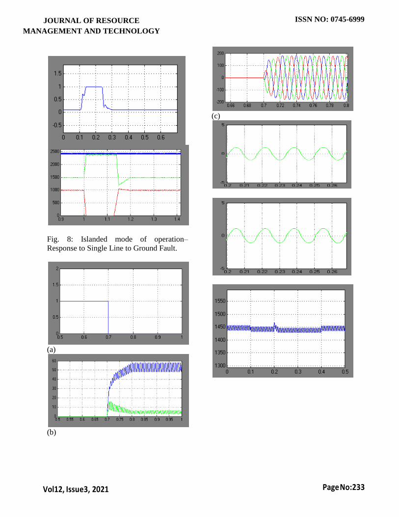
Single Line to Ground Fault:
The microgrid was operating in the Islanded
mode of operation. Suddenly at t=1.0s, a
temporary single line to ground fault has
occurred at node – 830 for a duration of
0.12s (shown in Fig. 8a).
JOURNAL OF RESOURCE
MANAGEMENT AND TECHNOLOGY
ISSN NO: 0745-6999
Vol12, Issue3, 2021
Page No:233
Fig. 8: Islanded mode of operation–
Response to Single Line to Ground Fault.
(a)
(b)
(c)
JOURNAL OF RESOURCE
MANAGEMENT AND TECHNOLOGY
ISSN NO: 0745-6999
Vol12, Issue3, 2021
Page No:234
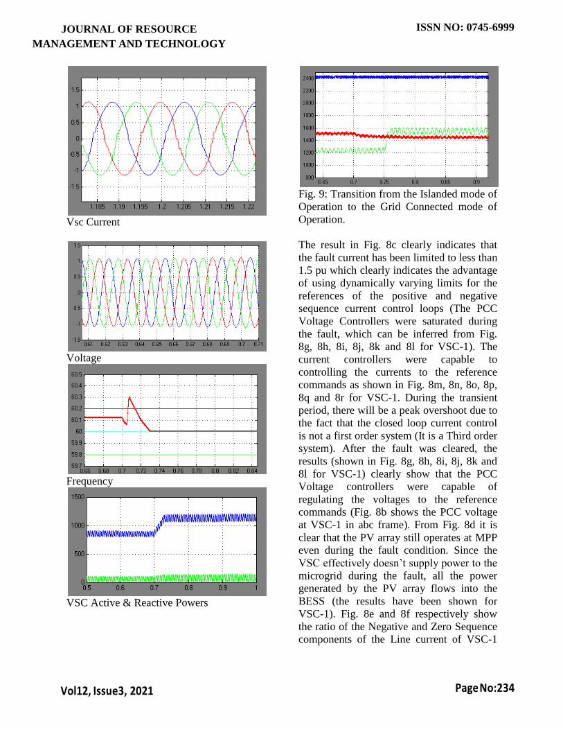
Vsc Current
Voltage
Frequency
VSC Active & Reactive Powers
Fig. 9: Transition from the Islanded mode of
Operation to the Grid Connected mode of
Operation.
The result in Fig. 8c clearly indicates that
the fault current has been limited to less than
1.5 pu which clearly indicates the advantage
of using dynamically varying limits for the
references of the positive and negative
sequence current control loops (The PCC
Voltage Controllers were saturated during
the fault, which can be inferred from Fig.
8g, 8h, 8i, 8j, 8k and 8l for VSC-1). The
current controllers were capable to
controlling the currents to the reference
commands as shown in Fig. 8m, 8n, 8o, 8p,
8q and 8r for VSC-1. During the transient
period, there will be a peak overshoot due to
the fact that the closed loop current control
is not a first order system (It is a Third order
system). After the fault was cleared, the
results (shown in Fig. 8g, 8h, 8i, 8j, 8k and
8l for VSC-1) clearly show that the PCC
Voltage controllers were capable of
regulating the voltages to the reference
commands (Fig. 8b shows the PCC voltage
at VSC-1 in abc frame). From Fig. 8d it is
clear that the PV array still operates at MPP
even during the fault condition. Since the
VSC effectively doesn’t supply power to the
microgrid during the fault, all the power
generated by the PV array flows into the
BESS (the results have been shown for
VSC-1). Fig. 8e and 8f respectively show
the ratio of the Negative and Zero Sequence
components of the Line current of VSC-1
JOURNAL OF RESOURCE
MANAGEMENT AND TECHNOLOGY
ISSN NO: 0745-6999
Vol12, Issue3, 2021
Page No:235
with respect to the Positive Sequence
component.
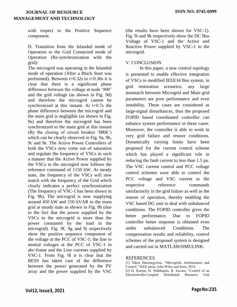
D. Transition from the Islanded mode of
Operation to the Grid Connected mode of
Operation (Re-synchronization with the
grid):
The microgrid was operating in the Islanded
mode of operation (After a Black Start was
performed). Between t=0.32s to t=0.36s it is
clear that there is a significant phase
difference between the voltage at node ‘800’
and the grid voltage (as shown in Fig. 9d)
and therefore the microgrid cannot be
synchronized at this instant. At t=0.7s the
phase difference between the microgrid and
the main grid is negligible (as shown in Fig.
9e) and therefore the microgrid has been
synchronized to the main grid at this instant
(By the closing of circuit breaker ‘BRK’)
which can be clearly observed in Fig. 9a, 9b,
9c and 9e. The Active Power Controllers of
both the VSCs now come out of saturation
and regulate the frequency of VSCs in such
a manner that the Active Power supplied by
the VSCs to the microgrid now follows the
reference command of 1150 kW. At steady
state, the frequency of the VSCs will now
match with the frequency of the Grid which
clearly indicates a perfect synchronization
(The frequency of VSC-1 has been shown in
Fig. 9h). The microgrid is now supplying
around 450 kW and 150 kVAR to the main
grid at steady state as shown in Fig. 9b (due
to the fact that the power supplied by the
VSCs to the microgrid is more than the
power consumed by the load in the
microgrid). Fig. 9f, 9g and 9j respectively
show the positive sequence component of
the voltage at the PCC of VSC-1; the line to
neutral voltages at the PCC of VSC-1 in
abc-frame and the Line currents supplied by
VSC-1. From Fig. 9l it is clear that the
BESS has taken care of the difference
between the power generated by the PV
array and the power supplied by the VSC
(the results have been shown for VSC-1).
Fig. 9i and 9k respectively show the DC Bus
Voltage of VSC-1 and the Active and
Reactive Power supplied by VSC-1 to the
microgrid.
V. CONCLUSION
In this paper, a new control topology
is presented to enable effective integration
of VSCs to modified IEEE34 Bus system. in
grid restoration scenarios, any large
mismatch between Microgrid and Main grid
parameters are poor performance and even
instability. These cases are considered as
large-signal disturbances, thus the proposed
FOPID based coordinated controller can
enhance system performance in these cases.
Moreover, the controller is able to work in
very grid failure and restore conditions.
Dynamically varying limits have been
proposed for the current control scheme
which has played a significant role in
reducing the fault current to less than 1.5 pu.
The VSC current control and PCC voltage
control schemes were able to control the
PCC voltage and VSC current to the
respective reference commands
satisfactorily in the grid failure as well as the
restore of operation, thereby enabling the
VSC based DG unit to deal with unbalanced
conditions. The FOPID controller gives the
better performance. Due to FOPID
controller better response is obtained even
under unbalanced Conditions. The
compensation results and reliability, control
schemes of the proposed system is designed
and carried out in MATLAB/SIMULINK.
REFERENCES [1] Nikos Hatziargyriou, “Microgrids Architectures and
Control,” IEEE press, John Wiley and Sons, 2014.
[2] H. Karimi, H. Nikkhajoei, R. Iravani, “Control of an
Electronically-Coupled Distributed Resource Unit

JOURNAL OF RESOURCE
MANAGEMENT AND TECHNOLOGY
ISSN NO: 0745-6999
Vol12, Issue3, 2021
Page No:236
Subsequent to an Islanding Event,” IEEE Transactions on
Power Delivery, vol. 23, no. 1, pp. 493–501, Jan 2008.
[3] H. Karimi, A. Yazdani, R. Iravani, “Robust Control of
an Autonomous Four Wire Electronically-Coupled
Distributed Generation Unit,” IEEE Transactions on Power
Delivery, vol. 26, no. 1, pp. 455–466, Jan 2011.
[4] F. Gao, R. Iravani, “A Control Strategy for a
Distributed Generation Unit in Grid- Connected and
Autonomous Modes of Operation,” IEEE Transactions on
Power Delivery, Vol 23, No 2, pp 850–859, Apr 2008.
[5] M. B. Delghavi, A. Yazdani, “A Unified Control
Strategy for Electronically Interfaced Distributed Energy
Resources,” IEEE Transactions on Power Delivery, vol. 27,
no. 2, pp. 803–812, Apr 2012.
[6] A. Yazdani, “Control of an Islanded Distributed Energy
Resource Unit with Load Compensating Feed-Forward,”
IEEE Power Engineering Society General Meeting,
7 pp. July 20–24, 2008.
[7] M. B. Delghavi and A. Yazdani, “A Control Strategy
for Islanded Operation of a Distributed Resource (DR)
Unit,” IEEE Power and Energy Society General Meeting, 8
pp. July 26–30, 2009.
[8] IEEE PES Distribution System Analysis Subcommittee
Radial Test Feeders. [Online]. Available:
http://ewh.ieee.org/soc/pes/dsacom/testfeeders/index.html.
[9] A. Yazdani, R. Iravani, “A Unified Dynamic Model and
Control for the Voltage- Sourced Converter Under
Unbalanced Grid Conditions,” IEEE Transactions on
Power Delivery, vol. 21, no. 3, pp. 1620–1629, Jul 2006.
[10] A. Yazdani, “Modelling and Control of the Three-
Level Neutral Point Diode Clamped (NPC) Converter for
High-Power Applications,” Ph.D. dissertation, Univ.
Toronto, Toronto, ON, Canada, 2005.
[11] N. Pogaku, M. Prodanovic, T. C. Green, “Modeling,
Analysis and Testing of Autonomous Operation of an
Inverter-Based Microgrid,” IEEE Transactions on Power
Electronics, Vol 22, No 2, pp 613–625, Mar 2007.
[12] M. B. Delghavi, A. Yazdani, “Islanded-Mode Control
of Electronically Coupled Distributed-Resource Units
Under Unbalanced and Nonlinear Load Conditions,” IEEE
Transactions on Power Delivery, vol. 26, no. 2, pp. 661–
673, Apr 2011.
[13] N. R. Merritt, C. Chakraborty, P. Bajpai, “A Control
Strategy for Islanded Operation of a Voltage Source
Converter (VSC) Based Distributed Resource Unit under
Unbalanced Conditions,” IEEE International Conference on
Industrial Informatics (INDIN), pp. 1550–1555, July 22–
24, 2015.
[14] M. Kumar, S. C. Srivastava,, S. N. Singh, “Control
Strategies of a DC Microgrid for Grid Connected and
Islanded Operations,” IEEE Transactions on Smart Grid,
vol. 6, no. 4, pp. 1588–1601, July 2015.
[15] M. Savaghebi, A. Jalilian, J. C. Vasquez, J. M.
Guerrero, “Secondary Control Scheme for Voltage
Unbalance Compensation in an Islanded Droop-Controlled
Microgrid”, IEEE Transactions on Smart Grid, Vol 3, No 2,
pp 797 807, June
2012.
[16] M. Savaghebi, A. Jalilian, J. C. Vasquez, J. M.
Guerrero, “Autonomous Voltage Unbalance Compensation
in an Islanded Droop-Controlled Microgrid,” IEEE
Transactions on Industrial Electronics, vol. 60, no. 4, pp.
1390–1402, Apr 2013.
[17] L. Meng, F. Tang, M. Savaghebi, J. C. Vasquez, J. M.
Guerrero, “Tertiary Control of Voltage Unbalance
Compensation for Optimal Power Quality in Islanded
Microgrids,” IEEE Transactions on Energy Conversion,
vol. 29, no. 4, pp. 802–815,
Dec 2014.
[18] Mohsen Hamzeh, H. Karimi, H. Mokhtari, “A New
Control Strategy for a Multi- Bus MV Microgrid Under
Unbalanced Conditions,” IEEE Transactions on Power
Systems, vol. 27, no. 4, pp. 2225–2232, Nov 2012.
[19] M. Chen, G. A. Rincon-Mora, “Accurate Electrical
Battery Model Capable of Predicting Runtime and IV
Performance,” IEEE Transactions on Energy Conversion,
vol. 21, no. 2, pp. 504–511, June 2006.
[20] M. G. Villalva, J. R. Gazoli, E. R. Filho,
“Comprehensive Approach to Modeling and Simulation of
Photovoltaic Arrays,” IEEE Transactions on Power
Electronics,
vol. 24, no. 5, pp. 1198–1208, May 2009.
[21] Y. A Mahmoud, W. Xiao, H. H. Zeineldin, “A
Parameterization Approach for Enhancing PV Model
Accuracy,” IEEE Transactions on Industrial Electronics,
vol.
60, no. 12, pp. 5708–5716, Dec 2013.
[22] A. K. Abdelsalam, A. M. Massoud, S. Ahmed, P. N.
Enjeti, “High-Performance Adaptive Perturb and Observe
MPPT Technique for Photovoltaic-Based Microgrids,”
IEEE Transactions on Power Electronics, vol. 26, no. 4, pp.
1010–1021,
Apr 2011.
[23] S. B. Kjaer, “Evaluation of the ‘Hill Climbing’ and the
‘Incremental Conductance’ Maximum Power Point
Trackers for Photovoltaic Power Systems,” IEEE
Transactions on Energy Conversion, vol. 27, no. 4, pp.
922–929, Dec 2012.
[24] D. Sera, L. Mathe, T. Kerekes, S.V. Spataru, R.
Teodorescu, “On the Perturb-and- Observe and Incremental
Conductance MPPT Methods for PV Systems,” IEEE
Journal of Photovoltaics, vol. 3, no. 3, pp. 1070–1078, Jul
2013.
[25] Y. Li, D. M. Vilathgamuwa, P. C. Loh, “Microgrid
power quality enhancement using a three-phase four-wire
grid-interfacing compensator,” IEEE Transactions on
Industry Applications, vol. 41, no. 6, pp. 1707-1719,
Nov/Dec. 2005.
[26] Fen Tang, Xiao Zhou, Lexuan Meng, J. M. Guerrero,
J. C. Vasquez, “Secondary voltage unbalance compensation
for three-phase four-wire islanded microgrids,”
International Multi-Conference on Systems, Signals &
Devices (SSD), Barcelona,
2014, pp. 1-5.
[27] A. Camacho, M. Castilla, J. Miret, A. Borrell, L. G. de
Vicua, “Active and Reactive Power Strategies With Peak
Current Limitation for Distributed Generation Inverters
During Unbalanced Grid Faults,” IEEE Transactions on
Industrial Electronics, vol.
62, no. 3, pp. 1515-1525, Mar 2015.
[28] N. R. Tummuru, M. K. Mishra, S. Srinivas, “An
Improved Current Controller for Grid Connected Voltage
Source Converter in Microgrid Applications,” IEEE

JOURNAL OF RESOURCE
MANAGEMENT AND TECHNOLOGY
ISSN NO: 0745-6999
Vol12, Issue3, 2021
Page No:237
Transactions on Sustainable Energy, vol. 6, no. 2, pp. 595-
605, Apr 2015. [29] L. Meng, X. Zhao, F. Tang, M.
Savaghebi, T. Dragicevic, J. C. Vasquez, J.
M. Guerrero, “Distributed Voltage
Unbalance Compensation in Islanded
Microgrids by Using a Dynamic Consensus
Algorithm,” IEEE Transactions on Power
Electronics,
vol. 31, no. 1, pp. 827-838, Jan 2016.
Recommended