FMP-ULSUNIVERSAL LIQUID SENSOR
INSTALLATION GUIDE
The information in this publication is provided for reference only. While every effort has been made to ensure the reliability and accuracy of the information contained in this manual at the time of printing, we recommend that you refer to “franklinfueling.com” for the most current version of this manual. All product specifications, as well as the information contained in this publication, are subject to change without notice. Franklin Fueling Systems does not assume responsibility and expressly disclaims liability for loss, damage, or expense arising out of, or in any way connected with, installation, operation, use, or maintenance by using this manual. Franklin Fueling Systems assumes no responsibility for any infringement of patents or other rights of third parties that may result from use of this manual or the products. We make no warranty of any kind with regard to this material, including, but not limited to, the implied warranties of merchantability and fitness for a particular purpose.
Copyright © 2017 Franklin Fueling Systems, Madison, WI 53718. All world rights reserved. No part of this publication may be stored in a retrieval system, transmitted, or reproduced in any way, including, but not limited to, photocopy, photograph, magnetic, or other record, without the prior written permission of Franklin Fueling Systems.
For technical assistance, please contact:
Franklin Fueling Systems 3760 Marsh Rd. Madison, WI 53718 USA
Web: franklinfueling.com Telephone: USA and Canada: +1.608.838.8786, +1.800.225.9787 USA and Canada Technical Support: +1.800.984.6266 UK: +44 (0) 1473.243300 Mexico: 001.800.738.7610 China: +86.10.8565.4566
Conventions used in this manualThis manual includes safety precautions and other important information presented in the following format:
NOTE: This provides helpful supplementary information.
IMPORTANT: This provides instructions to avoid damaging hardware or a potential hazard to the environment, for example: fuel leakage from equipment that could harm the environment.
CAUTION: This indicates a potentially hazardous situation that could result in minor or moderate injury if not avoided. This may also be used to alert against unsafe practices.
WARNING: This indicates a potentially hazardous situation that could result in severe injury or death if not avoided.
DANGER: This indicates an imminently hazardous situation that will result in death if not avoided.
Operating precautionsFranklin Fueling Systems (FFS) equipment is designed to be installed in areas where volatile liquids such as gasoline and diesel fuel are present. Working in such a hazardous environment presents a risk of severe injury or death if you do not follow standard industry practices and the instructions in this manual. Before you work with or install the equipment covered in this manual, or any related equipment, read this entire manual, particularly the following precautions:
IMPORTANT: To help prevent spillage from an underground storage tank, make sure the delivery equipment is well-maintained, that there is a proper connection, and that the fill adaptor is tight. Delivery personnel should inspect delivery elbows and hoses for damage and missing parts.
CAUTION: Use only original FFS parts. Substituting non-FFS parts could cause the device to fail, which could create a hazardous condition and/or harm the environment.
WARNING: Follow all codes that govern how you install and service this product and the entire system. Always lock out and tag electrical circuit breakers while installing or servicing this equipment and related equipment. A potentially lethal electrical shock hazard and the possibility of an explosion or fire from a spark can result if the electrical circuit breakers are accidentally turned on while you are installing or servicing this product. Refer to this manual (and documentation for related equipment) for complete installation and safety information.
WARNING: Before you enter a containment sump, check for the presence of hydrocarbon vapors. Inhaling these vapors can make you dizzy or unconscious, and if ignited, they can explode and cause serious injury or death. Containment sumps are designed to trap hazardous liquid spills and prevent environmental contamination, so they can accumulate dangerous amounts of hydrocarbon vapors. Check the atmosphere in the sump regularly while you are working in it. If vapors reach unsafe levels, exit the sump and ventilate it with fresh air before you resume working. Always have another person standing by for assistance.
WARNING: Follow all federal, state, and local laws governing the installation of this product and its associated systems. When no other regulations apply, follow NFPA codes 30, 30A, and 70 from the National Fire Protection Association. Failure to follow these codes could result in severe injury, death, serious property damage, and/or environmental contamination.
WARNING: Always secure the work area from moving vehicles. The equipment in this manual is usually mounted underground, so reduced visibility puts service personnel working on it in danger from moving vehicles that enter the work area. To help prevent this safety hazard, secure the area by using a service truck (or some other vehicle) to block access to the work area.
DANGER: Make sure you check the installation location for potential ignition sources such as flames, sparks, radio waves, ionizing radiation, and ultrasound sonic waves. If you identify any potential ignition sources, you must make sure safety measure are implemented.
1
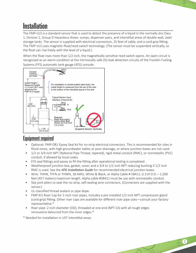
InstallationThe FMP-ULS is a standard sensor that is used to detect the presence of a liquid in the normally dry Class 1, Division 1, Group D Hazardous Areas: sumps, dispenser-pans, and interstitial areas of double-wall, steel storage tanks. The sensor is supplied with electrical connectors, 25 feet of cable, and a cord-grip fitting. The FMP-ULS uses magnetic-float/reed-switch technology. (The sensor must be suspended vertically, so the float can rise freely with the level of a liquid.)
When the float rises more than 1/2 inch, the magnetically sensitive reed switch opens. An open circuit is recognized as an alarm-condition at the intrinsically safe (IS) leak detection circuits of the Franklin Fueling Systems (FFS) automatic tank gauge (ATG) console.
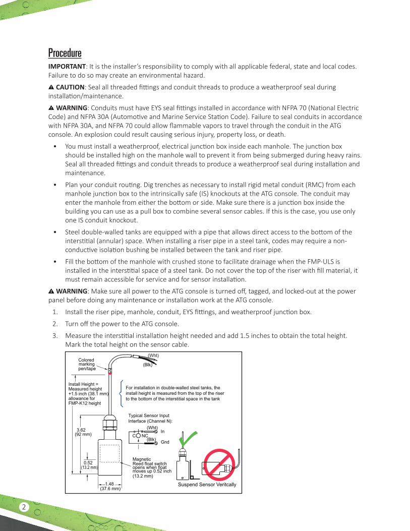
MagneticReed float switchopens when floatmoves up 0.52 inch(13.2 mm)
(Wht)
(Blk)
(Wht)
(Blk)
Typical Sensor Input Interface (Channel N):
For installation in double-walled steel tanks, the install height is measured from the top of the riser to the bottom of the interstitial space in the tank
1.48(37.6 mm)
0.52(13.2 mm)
3.62(92 mm) C NC
Install Height =Measured height+1.5 inch (38.1 mm) allowance for FMP-K12 height
Coloredmarkingpen/tape
Gnd
In
Suspend Sensor Veritcally
Equipment required• Optional: FMP-DB1 Epoxy Seal kit for no-strip electrical connectors. This is recommended for sites in
flood zones, with high groundwater tables or poor drainage, or where junction boxes are not used.• 1/2 or 3/4 inch NPT (National Pipe Thread, tapered), rigid metal conduit (RMC), or nonmetallic (PVC)
conduit, if allowed by local codes. • EYS seal fittings and epoxy to fill the fitting after operational testing is completed.• Weatherproof junction box, gasket, cover, and a 3/4 to 1/2 inch NPT reducing bushing if 1/2 inch
RMC is used. See the ATG Installation Guide for recommended electrical junction boxes.• Wire: THHN, TFFN or THWN, 18 AWG, White & Black, or Alpha Cable # 58411, 0.114 O.D.—1,500
feet (457 meters) maximum length. Alpha cable #58411 must be use with nonmetallic conduit.• Slip joint pliers to seat the no-strip, self-sealing wire connectors. (Connectors are supplied with the
sensor.)• UL-classified thread sealant or pipe dope. • FMP-KI2 Riser Cap for 2-inch riser pipes, includes a pre-installed 1/2 inch NPT compression gland
(cord-grip) fitting. Other riser caps are available for different riser pipe sizes—consult your factory representative.*
• Riser pipe: 2 inch diameter (OD), threaded at one end (NPT-14) with all rough edges removed or deburred from the inner edges.*
* Needed for installation in UST interstitial areas.
2
ProcedureIMPORTANT: It is the installer’s responsibility to comply with all applicable federal, state and local codes. Failure to do so may create an environmental hazard.
CAUTION: Seal all threaded fittings and conduit threads to produce a weatherproof seal during installation/maintenance.
WARNING: Conduits must have EYS seal fittings installed in accordance with NFPA 70 (National Electric Code) and NFPA 30A (Automotive and Marine Service Station Code). Failure to seal conduits in accordance with NFPA 30A, and NFPA 70 could allow flammable vapors to travel through the conduit in the ATG console. An explosion could result causing serious injury, property loss, or death.
• You must install a weatherproof, electrical junction box inside each manhole. The junction box should be installed high on the manhole wall to prevent it from being submerged during heavy rains. Seal all threaded fittings and conduit threads to produce a weatherproof seal during installation and maintenance.
• Plan your conduit routing. Dig trenches as necessary to install rigid metal conduit (RMC) from each manhole junction box to the intrinsically safe (IS) knockouts at the ATG console. The conduit may enter the manhole from either the bottom or side. Make sure there is a junction box inside the building you can use as a pull box to combine several sensor cables. If this is the case, you use only one IS conduit knockout.
• Steel double-walled tanks are equipped with a pipe that allows direct access to the bottom of the interstitial (annular) space. When installing a riser pipe in a steel tank, codes may require a non-conductive isolation bushing be installed between the tank and riser pipe.
• Fill the bottom of the manhole with crushed stone to facilitate drainage when the FMP-ULS is installed in the interstitial space of a steel tank. Do not cover the top of the riser with fill material, it must remain accessible for service and for sensor installation.
WARNING: Make sure all power to the ATG console is turned off, tagged, and locked-out at the power panel before doing any maintenance or installation work at the ATG console.
1. Install the riser pipe, manhole, conduit, EYS fittings, and weatherproof junction box.
2. Turn off the power to the ATG console.
3. Measure the interstitial installation height needed and add 1.5 inches to obtain the total height. Mark the total height on the sensor cable.
MagneticReed float switchopens when floatmoves up 0.52 inch(13.2 mm)
(Wht)
(Blk)
(Wht)
(Blk)
Typical Sensor Input Interface (Channel N):
For installation in double-walled steel tanks, the install height is measured from the top of the riser to the bottom of the interstitial space in the tank
1.48(37.6 mm)
0.52(13.2 mm)
3.62(92 mm) C NC
Install Height =Measured height+1.5 inch (38.1 mm) allowance for FMP-K12 height
Coloredmarkingpen/tape
Gnd
In
Suspend Sensor Veritcally
3
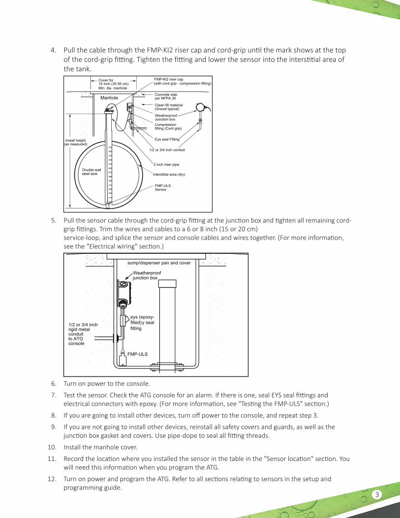
4. Pull the cable through the FMP-KI2 riser cap and cord-grip until the mark shows at the top of the cord-grip fitting. Tighten the fitting and lower the sensor into the interstitial area of the tank.
Double-wallsteel tank
Install height(as measured)
Cover for14 inch (35.56 cm)Min. dia. manhole
Manhole
2 inch riser pipe
1/2 or 3/4 inch conduit
Eys seal Fitting
Interstitial area (dry)
FMP-ULSSensor
Concrete slabper NFPA 30
FMP-Kl2 riser cap(with cord grip - compression fitting)
Clean fill material(Gravel typical)
WeatherproofJunction boxCompressionfitting (Cord grip)
5. Pull the sensor cable through the cord-grip fitting at the junction box and tighten all remaining cord-grip fittings. Trim the wires and cables to a 6 or 8 inch (15 or 20 cm) service-loop, and splice the sensor and console cables and wires together. (For more information, see the "Electrical wiring" section.)
eys (epoxy- filled)y sealfitting
FMP-ULS
sump/dispenser pan and cover
Weatherproofjunction box
1/2 or 3/4 inchrigid metalconduitto ATGconsole
6. Turn on power to the console.
7. Test the sensor. Check the ATG console for an alarm. If there is one, seal EYS seal fittings and electrical connectors with epoxy. (For more information, see "Testing the FMP-ULS" section.)
8. If you are going to install other devices, turn off power to the console, and repeat step 3.
9. If you are not going to install other devices, reinstall all safety covers and guards, as well as the junction box gasket and covers. Use pipe-dope to seal all fitting threads.
10. Install the manhole cover.
11. Record the location where you installed the sensor in the table in the "Sensor location" section. You will need this information when you program the ATG.
12. Turn on power and program the ATG. Refer to all sections relating to sensors in the setup and programming guide.
228180007 r1
A Franklin Fueling Systems Brand
Electrical wiring
2 wires/cable from console2-conductor cable from sensor
J-box
From 2-wire sensor
SENS
OR N
IN(WHT)
Note: The PWR (red)terminal is not used with2-wire sensors
GND(BLK)
PWR(RED)
PWR(RED)
SENS
OR 1
IN(WHT)
GND(BLK)
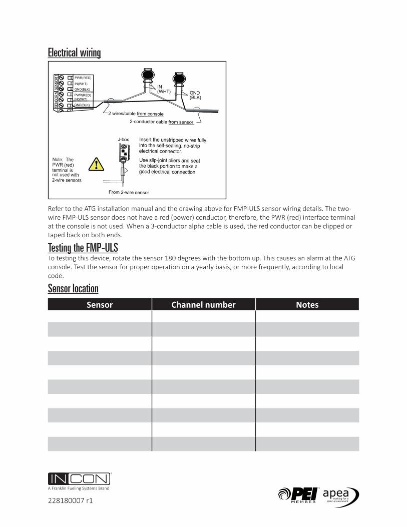
Insert the unstripped wires fully into the self-sealing, no-strip electrical connector.Use slip-joint pliers and seat the black portion to make a good electrical connection
IN(WHT) GND
(BLK)
Refer to the ATG installation manual and the drawing above for FMP-ULS sensor wiring details. The two-wire FMP-ULS sensor does not have a red (power) conductor, therefore, the PWR (red) interface terminal at the console is not used. When a 3-conductor alpha cable is used, the red conductor can be clipped or taped back on both ends.
Testing the FMP-ULSTo testing this device, rotate the sensor 180 degrees with the bottom up. This causes an alarm at the ATG console. Test the sensor for proper operation on a yearly basis, or more frequently, according to local code.
Sensor locationSensor Channel number NotesSensor Channel # / Notes
Recommended