Flow MeasurementSITRANS F C
Transmitter FCT030
1 Siemens FI 01 News · 2012 US Edition
■ Overview
FCT030 is based on the latest developments within digital signal processing technology – engineered for high measuring perfor-mance, fast response to step changes in flow, fast dosing appli-cations, high immunity against process noise, easy to install commission and maintain.
The FCT030 transmitter delivers true multi-parameter measure-ments i.e. massflow, volumeflow, corrected volumeflow, density, temperature and fraction.
The FCT030 IP67 transmitter can be remote connected or com-pact mounted with all sensors of type FCS400, sizes DN 15 to DN 80.
■ Application
SITRANS FC430 mass flowmeters are suitable for applications within the entire process industry where there is a demand for accurate flow measurement. The meter is capable of measuring both liquid and gas flow.
Coriolis flowmeters can be applied in all industries, such as:• Chemical & Pharma: detergents, bulk chemicals, acids, alka-
lis, pharmaceuticals, blood products, vaccines, insulin pro-duction
• Food & Beverage: dairy products, beer, wine, soft drinks, °Brix/°Plato, fruit juices and pulps, bottling, CO2 dosing, CIP/SIP-liquids, mixture recipe control
• Automotive: fuel injection nozzle & pump testing, filling of AC units, engine consumption
• Oil & Gas: filling of gas bottles, furnace control, test separators • Hydrocarbon processing: oil refining, derivatives manufactur-
ing, polymerisation • Water & Waste Water: dosing of chemicals for water treatment
The multiple outputs and bus communication mean that all of the process information can be read either instantaneously (10 ms update) or periodically as plant operation requires.
■ Benefits
Flow calculation and measurement• Dedicated mass flow calculation with patented DSP technol-
ogy• Fast dosing and flow step response with maximum 10 ms re-
sponse time.• 100 Hz update rate to all outputs• Maximum data age from pickup to output is 20 ms (two update
cycles)• Independent low flow cut-off settings for mass and volume
flowrates
• Automatic zero-point adjustment on command• Empty pipe monitoring
Operation and display• User-configurable operation display
- Full graphical display 240 x 160 pixels with up to 6 program-mable views
- Self-explaining alarm handling/log in clear text- Help text for all parameters appears automatically in the con-
figuration menu- Keypad can be used for controlling dosing as start/stop/
hold/reset• SensorFlash technology stores production specific system
documentation and provides removable memory of all flow-meter setups and functions- Calibration certificates- Pressure and material test certificates (as ordered)- Non-volatile memory backup of operational data- Transfer of user configuration to other flowmeters
Alarms and safety• Advanced diagnosis and service menu enhances trouble-
shooting and meter validation• Configurable upper and lower alarms and warning limits for all
process values• Alarm handling can be selected between Siemens and
NAMUR standard configurations• Designed from the ground up and certified to integrated
safety levels as:- SIL 3 for software- SIL 2 for hardware and mechanics- SIL 3 for a system with redundant hardwareUnlike many systems which are certified in practice, the SITRANS FC430 system is certified in design, which is a higher qualification and more robust for secure implementa-tion of safety systems.
Outputs and control• Built-in dosing controller with compensation and monitoring
comprising 3 built-in totalizers• Multi-parameter outputs, individually configurable for mass-
flow, volumeflow, corrected volumeflow, density, temperature or fraction flow such as °Brix or °Plato
Up to four I/O channels are configured as follows:
Channel 1
Channel 1 is 4 to 20 mA analog output with HART 7.2 which can be validated and setup for safety critical applications (SIL 3). The current signal can be configured for massflow, volumeflow or density.
Channel 2
Channel 2 is a signal output which can be freely configured for any process variable.• Analog current (0/4 to 20 mA)• 3 stage analog valve dosing control• Frequency or pulse• Discrete one or two-valve dosing control in combination with
channel 3 or 4• Operational and alarm status
Channels 3 and 4
Channels 3 and 4 can be ordered with signal (freely configured for any process variable) or relay outputs, or signal input.
© Siemens AG 2012
Flow MeasurementSITRANS F C
Transmitter FCT030
2Siemens FI 01 News · 2012 US Edition
Signal
Signal output can be user configured to:• Analog current (0/4 to 20 mA)• 3 stage analog valve dosing control• Frequency or pulse• Redundant frequency or pulse (linked to Channel 2)• Discrete one or two-valve dosing control• Operational and alarm status
Relay
Relay output(s) can be user configured to:• Discrete one or two-valve dosing control• Operation status including flow direction• Alarm status
Signal input
Signal input can be user-configured for• Dosing control• Totalizer reset functions• Force or freeze output(s)
Signal outputs and inputs are individually ordered as active or passive.
During service and maintenance all outputs can be forced to a preset value for simulation, verification or calibration purposes.
Approvals and certificates
The FC430 coriolis flowmeter program was designed from the ground up to comply with or exceed the requirements of interna-tional standards and regulations.
■ Design
The transmitter SITRANS FCT030 is designed in an IP67/NEMA 4X aluminum enclosure with corrosion resistant coating. It can be remote connected or compact mounted with an FCS400 sensor of size DN 15, DN 25, DN 50 or DN 80.
FCT030 is available as standard with 1 current, HART 7.2 output and can be fitted with add-on modules for additional input/out-put functions.
The transmitter has a modular design with discrete, replaceable electronic modules and connection boards to maintain separa-tion between functions and facilitate field service. All modules are fully traceable and their provenance is included in the trans-mitter setup.
SensorFlash
SensorFlash is a standard, 1 GByte micro SD card with the ability to be updated by PC. It is supplied with each sensor with the complete set of certification documents including calibration re-port. Material, pressure test, factory conformance certificates are optional at ordering.
The Siemens SensorFlash memory unit offers the following fea-tures and benefits: • Automatically program any similar transmitter in seconds to
the operation standard• Transmitter replacement in less than 5 minutes• True "plug & play" provided by integrated cross-checking data
consistency and HW/SW version verification• Permanent database of operational and functional information
from the moment that the flowmeter is switched on• New firmware updates can be downloaded from the SIEMENS
internet portal for Product Support and placed onto Sensor-Flash (unmounted from the transmitter and inserted into a PC’s SD card slot). The firmware is then inserted into the existing flowmeter and the complete system upgraded.
■ Function
The following functions are available:• Mass flowrate, volume flowrate, density, process temperature,
fraction flow• Up to four output/input channels selected at ordering• Outputs can be individually configured with mass, volume,
density etc.• 3 built-in totalizers which can count positive, negative or net
flows• Low flow cut-off, adjustable• Density cut-off or empty pipe cut-off, adjustable• Flow direction adjustable• Alarm system consisting of alarm-log, alarm pending menu• Internal data logger is updated each 10 minutes with opera-
tional data such as system health, totalizer values, all configu-rations and data needed for Custody Transfer requirements to OIML R 117
• Display of operating time with real-time clock. Daylight saving time is not implemented
• Uni/bidirectional flow measurement• Flowrate outputs are freely configurable between maximum
negative and maximum positive flows according to the sensor capacity
• Limit switches programmable for flow, density, temperature or fraction process values. Limit points can be graded as warn-ing and alarm for values both above and below nominal pro-cess conditions
• Process noise filter for optimization of measurement perfor-mance under non-ideal application conditions. 5-stage pump-ing filter compensates for flow fluctuations caused by e.g. sin-gle acting piston pumps
• Full dosing controller with 5 user-configurable recipes• Automatic zero adjustment menu, with zero point evaluation
display• Full service menu for effective and straight forward application
and meter troubleshooting • Precise temperature measurement ensures optimum accu-
racy on massflow, density and fraction flow.• Fraction flow computation is based on a 5th-order algorithm
matching known applications. Users can either select from a list of pre-configured fractions such as °Brix or "Ethanol in wa-ter", or order a specific fraction calibration to exactly match the process conditions. All fraction calculations fit within 0.1% of the true value.
© Siemens AG 2012
Flow MeasurementSITRANS F C
Transmitter FCT030
3 Siemens FI 01 News · 2012 US Edition
■ Technical specifications
Process media • Fluid Group 1 (suitable for dan-gerous fluids)
• Aggegate state: Paste/light slur-ry, liquid and gas
Number of process variables 7
Measurement of • Mass flow
• Volume flow
• Density
• Process media temperature
• Corrected volume flow
• Reference density
• Fraction A flow
• Fraction B flow
• Fraction A %
• Fraction B %
Current output
Current 0 ... 20 mA or 4 ... 20 mA (Channel 1 ony 4 ... 20 mA)
Load < 500 Ω per channel
Time constant 0 ... 100 s adjustable
Digital output
Pulse 41.6 µs ... 5 s pulse duration
Frequency 0 ... 10 kHz, 50 % duty cycle, 120 % overscale provision
Time constant 0 ... 100 s adjustable
Active 0 ... 24 V DC, 110 mA, short-circuit-protected
Passive 3 ... 30 V DC, max. 110 mA
Relay
Type Change-over voltage-free relay contact
Load 30 V AC/100 mA
Functions Alarm level, alarm number, limit, flow direction
Digital input
Voltage 15 ... 30 V DC (2 ... 15 mA)
Functionality Start/stop/hold/continue dosing, zero point adjust, reset totalizer 1 and 2, force output, freeze output
Galvanic isolation All inputs and outputs are galva-nically isolated, isolation voltage 500 V.
Cut-off
Low-flow 0 ... 9.9 % of maximum flow
Limit function Mass flow, volume flow, fraction, density, sensor temperature
Totalizer Two eight-digit counters for for-ward, net or reverse flow
Display • Background illumination with al-phanumerical text, 3 × 20 char-acters to indicate flow rate, totalized values, settings and faults.
• Time constant as current output 1
• Reverse flow indicated by nega-tive sign
Zero point adjustment Via keypad or remote via digital input
Ambient temperature
Operation
• Transmitter -40 ... +60 °C (-40 ... +140 °F), (humidity max. 95 %)
• Display -20 ... +60 °C (-4 ... 140 °F)
Storage
• Transmitter -40 ... +70 °C (-40 ... +158 °F) (Humidity max. 95 %)
• Display -20 ... +70 °C (-4 ... +158 °F)
Communication HART 7.2
Enclosure
Material Aluminum
Rating IP67/NEMA 4X to IEC 529 and DIN 40050 (1 mH2O for 30 min.)
Mechanical load 18 ... 1000 Hz random, 3.17 g RMS, in all directions, to IEC 68-2-36
Supply voltage
Supply 18.5 ... 300 V DC/85 ... 260 V AC, 50 ... 60 Hz
Fluctuation No limit
Power consumption 7.5 W/15 VA
EMC performance
Emission EN/IEC 61000-6-4 (Industry)
Immunity EN/IEC 61000-6-2 (Industry)
NAMUR Within the value limits according to "General requirements" with error criteria A in accordance with NE 21
Environment Within the value limits according to "General requirements" with alarm criteria A in accordance with NE 21
Environmental conditions acc. to IEC/EN/UL 61010-1
• Altitude up to 2000 m• Pollution degree 2
Maintenance The flowmeter has a built-in error log/pending menu which should be inspected on a regular basis.
Cable glands Cable gland are available in Nylon, Nickel plated brass or stainless steel (316L/W1.4404) in the following dimensions:• M20• ½" NPT
Cable Standard industrial signal cable up to 200 m long with 2 x screened pairs or 4-wire overall screen can be laid between the sensor and transmitter. Siemens offers cables in a selection of pre-cut lengths and prepared for either gland or plug connection.
© Siemens AG 2012
Flow MeasurementSITRANS F C
Transmitter FCT030
4Siemens FI 01 News · 2012 US Edition
Approvals
Hazardous area • ATEX Ex II 2(1) GD Ex d e [ia] ia IIC T6 Gb
• FM/CSA Class1 Div. 1
• IEC Ex II 2(1) GDEx d e [ia] ia IIC T6 Gb
Custody transfer • OIML R 117 type approval to a wide variety of liquids other than water
• NTEP (USA) type evaluation pro-gram approval to a wide variety of liquids
Pressure equipment • PED
• CRN
• Unfired pressure vessels (UK)
Hygienic applications • EHEDG for all sensors
• 3A for hygienic variant sensors
• External cleanability satisfies EHEDG and 3A rules
Certificates
Safety Integration Level (applies only to compact versions)
• SIL 3 for software
• SIL 2 for hardware
• SIL 3 for redundant hardware systems
CE mark • Pressure equipment
• Low voltage directive
• WEEE
• RoHS
Regional certifications • C-TICK (Australia and New Zea-land EMC)
• NEPSI (China Ex)
• TISS (Japan)
© Siemens AG 2012
Flow MeasurementSITRANS F C
Flow sensor SITRANS FCS400
5 Siemens FI 01 News · 2012 US Edition
■ Overview
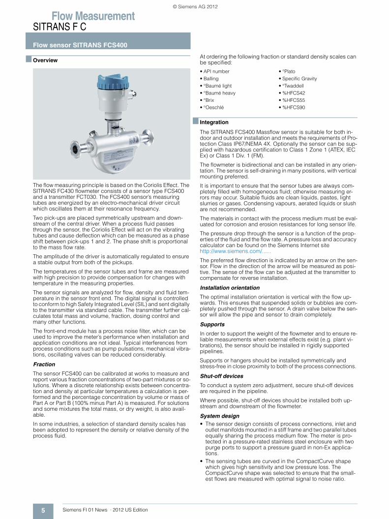
The flow measuring principle is based on the Coriolis Effect. The SITRANS FC430 flowmeter consists of a sensor type FCS400 and a transmitter FCT030. The FCS400 sensor’s measuring tubes are energized by an electro-mechanical driver circuit which oscillates them at their resonance frequency.
Two pick-ups are placed symmetrically upstream and down-stream of the central driver. When a process fluid passes through the sensor, the Coriolis Effect will act on the vibrating tubes and cause deflection which can be measured as a phase shift between pick-ups 1 and 2. The phase shift is proportional to the mass flow rate.
The amplitude of the driver is automatically regulated to ensure a stable output from both of the pickups.
The temperatures of the sensor tubes and frame are measured with high precision to provide compensation for changes with temperature in the measuring properties.
The sensor signals are analyzed for flow, density and fluid tem-perature in the sensor front end. The digital signal is controlled to conform to high Safety Integrated Level (SIL) and sent digitally to the transmitter via standard cable. The transmitter further cal-culates total mass and volume, fraction, dosing control and many other functions.
The front-end module has a process noise filter, which can be used to improve the meter’s performance when installation and application conditions are not ideal. Typical interferences from process conditions such as pump pulsations, mechanical vibra-tions, oscillating valves can be reduced considerably.
Fraction
The sensor FCS400 can be calibrated at works to measure and report various fraction concentrations of two-part mixtures or so-lutions. Where a discrete relationship exists between concentra-tion and density at particular temperatures a calculation is per-formed and the percentage concentration by volume or mass of Part A or Part B (100% minus Part A) is measured. For solutions and some mixtures the total mass, or dry weight, is also avail-able.
In some industries, a selection of standard density scales has been adopted to represent the density or relative density of the process fluid.
At ordering the following fraction or standard density scales can be specified:
■ Integration
The SITRANS FCS400 Massflow sensor is suitable for both in-door and outdoor installation and meets the requirements of Pro-tection Class IP67/NEMA 4X. Optionally the sensor can be sup-plied with hazardous certification to Class 1 Zone 1 (ATEX, IEC Ex) or Class 1 Div. 1 (FM).
The flowmeter is bidirectional and can be installed in any orien-tation. The sensor is self-draining in many positions, with vertical mounting preferred.
It is important to ensure that the sensor tubes are always com-pletely filled with homogeneous fluid; otherwise measuring er-rors may occur. Suitable fluids are clean liquids, pastes, light slurries or gases. Condensing vapours, aerated liquids or slush are not recommended.
The materials in contact with the process medium must be eval-uated for corrosion and erosion resistances for long sensor life.
The pressure drop through the sensor is a function of the prop-erties of the fluid and the flow rate. A pressure loss and accuracy calculator can be found on the Siemens Internet site http://www.siemens.com/......
The preferred flow direction is indicated by an arrow on the sen-sor. Flow in the direction of the arrow will be measured as posi-tive. The sense of the flow can be adjusted at the transmitter to compensate for reverse installation.
Installation orientation
The optimal installation orientation is vertical with the flow up-wards. This ensures that suspended solids or bubbles are com-pletely pushed through the sensor. A drain valve below the sen-sor will allow the pipe and sensor to drain completely.
Supports
In order to support the weight of the flowmeter and to ensure re-liable measurements when external effects exist (e.g. plant vi-brations), the sensor should be installed in rigidly supported pipelines.
Supports or hangers should be installed symmetrically and stress-free in close proximity to both of the process connections.
Shut-off devices
To conduct a system zero adjustment, secure shut-off devices are required in the pipeline.
Where possible, shut-off devices should be installed both up-stream and downstream of the flowmeter.
System design• The sensor design consists of process connections, inlet and
outlet manifolds mounted in a stiff frame and two parallel tubes equally sharing the process medium flow. The meter is pro-tected in a pressure-rated stainless steel enclosure with two purge ports to support a pressure guard in non-Ex applica-tions.
• The sensing tubes are curved in the CompactCurve shape which gives high sensitivity and low pressure loss. The CompactCurve shape was selected to ensure that the small-est flows are measured with optimal signal to noise ratio.
• API number• Balling• °Baumé light• °Baumé heavy • °Brix • °Oeschlé
• °Plato• Specific Gravity • °Twaddell• %HFCS42• %HFCS55• %HFCS90
© Siemens AG 2012
Flow MeasurementSITRANS F C
Flow sensor SITRANS FCS400
6Siemens FI 01 News · 2012 US Edition
• Patented vibration mode separation creates a controlled mea-suring environment only within the CompactCurve part of the tubes. As a result the sensor has high immunity to plant vibra-tion while avoiding large mass balancing of the meter compo-nents.
• The 15° slope of the CompactCurve shape ensures secure self-draining when the sensor axis is mounted vertically or up to 10° off vertical.
• The sensor frame is designed to conduct plant vibrations di-rectly through the sensor body to adjacent pipeline while pro-viding isolation of the metering section from the vibration. Careful mounting of the pipeline with regard to minimizing vi-bration at the meter will ensure a secure measurement envi-ronment.
■ Installation guidelines
• The mass flowmeter does not require any flow conditioning or straight inlet pipe sections. Care should be exercised however to ensure that any upstream valves, gates, sight glasses etc. do not cavitate and are not set into vibration by the flow.
• It is always preferred to place the flowmeter upstream of any control valve (what goes in, comes out) or other pipeline com-ponent which may cause flashing, cavitation or vibrations.
• The presence of gas bubbles in the fluid may result in errone-ous measurements, particularly in the density measurement. Therefore the flowmeter should not be installed at the highest point in the liquid piping system or where vapour can collect. Install the meter low in pipeline sections to maintain system pressure and compress any bubbles.
• Drop lines downstream from the flow sensor should be avoided to prevent the meter tube from draining during flowing conditions. A back-pressure device or orifice is recom-mended to ensure that flow does not separate within the flow sensor but the metering section remains at positive pressure at all times while there is flow.
• The flowmeter should not come into contact with any other ob-jects. Avoid making attachments to the housing except for the pressure guard components (if required).
• When the connecting pipeline is larger than the sensor size, suitable standard reducers may be installed. A selection of oversize and undersize connections can be ordered - refer to the sizes tables below.
• If strong vibrations exist in the pipeline, they should be damped using elastic pipeline elements. The damping de-vices must be installed outside the supported flowmeter sec-tion. Direct connection of flexible elements to the sensor should be avoided.
• Make sure that any dissolved gases, which are present in many liquids, do not outgas. The back pressure at the outlet should be at least 0.2 bar (3 psi) above the vapour pressure of the process fluid.
• Assure that operation below the vapour pressure cannot occur particularly for fluids with low latent heat of vaporisation.
• The sensor should not be installed in the vicinity of strong elec-tromagnetic fields, e.g. near motors, pumps, variable fre-quency drives, transformers etc.
• When operating meters on a common mounting base the sen-sors should be mounted and spaced separate from each other to avoid cross-talk and other vibration interferences.
• When operating meters in interconnected pipelines the pipes should be decoupled to prevent cross talk.
Remote system cabling
The system is designed so that standard instrumentation cable with four cores and overall screen or two screened pairs can be used, or cable sets can be ordered with the flowmeter. The cable can be ordered in various set lengths and terminated in the field.
The maximum design length for the sensor cable is 200 m (656.17 ft). Data transmission speed and process variable up-
date rates may be affected by the cable characteristics. For best results, choose a cable with the following electrical characteris-tics:
The flowmeter system applies maximum 15 V DC in operation and is certified intrinsically safe. The complete system is insula-tion tested to 1500 V in production.
Cabling solutions which can be ordered with the flowmeter are as follows:
1. High performance plugged cable using M12 plugs into pre-pared sockets
2. Cable glands for either metric or NPT threaded terminal hous-ings.
3. Plain cable in set lengths to be passed through flexible and rigid conduit (not supplied) for metric or NPT threaded termi-nal housings
Cable for items 1, 2 and 3 are available either gray for standard applications or light blue for Ex applications to identify the circuit as intrinsically safe.
Insulation and heating
For applications where pipeline insulation is required for person-nel protection or process temperature maintenance, the SITRANS FCS400 flow sensor may also be insulated. The form and material of insulation is not prescribed and entirely depends on the practices at the application location or plant.
Insulation must not be crowded around the sensor pedestal but shaped at a 45° cone to allow the pedestal to radiate excess heat and maintain a suitable working temperature within the front-end housing.
Where trace heating is employed, an electric heating jacket can be ordered as an accessory. It is shaped to the sensor body and controlled from a weatherproof setpoint device.
The jacket can heat the sensor enclosure up to 200 °C (392 °F). However further insulation is also recommended for personnel protection or low loss temperature maintenance.
Calibration
To ensure accurate measurement all flowmeters must be initially calibrated. The calibration of each SITRANS FCS400 coriolis sensor is conducted at SIEMENS flow facilities accredited ac-cording to ISO/IEC 17025 by DANAK. A calibration certificate is shipped with every sensor and calibration data are stored in the SensorFlash memory unit. The accreditation body DANAK has signed the ILAC MRA agreement (International Laboratory Ac-creditation Corporation - Mutual Recognition Arrangement). Therefore the accreditation ensures international traceability and recognition of the test results in 39 countries worldwide, includ-ing the US (NIST traceability).
Property Unit Value
Resistance [Ω/km] 59
Characteristic impedance [Ω] 100 @ 1 MHz
Insulation resistance [MΩ/km] 200
Maximum voltage [V] 300
© Siemens AG 2012
Flow MeasurementSITRANS F C
Flow sensor SITRANS FCS400
7 Siemens FI 01 News · 2012 US Edition
■ Technical specifications
Pressure/temperature curves
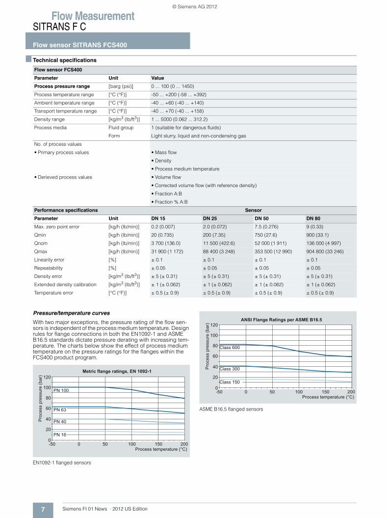
With two major exceptions, the pressure rating of the flow sen-sors is independent of the process medium temperature. Design rules for flange connections in both the EN1092-1 and ASME B16.5 standards dictate pressure derating with increasing tem-perature. The charts below show the effect of process medium temperature on the pressure ratings for the flanges within the FCS400 product program.
EN1092-1 flanged sensors
ASME B16.5 flanged sensors
Flow sensor FCS400
Parameter Unit Value
Process pressure range [barg (psi)] 0 ... 100 (0 ... 1450)
Process temperature range [°C (°F)] -50 ... +200 (-58 ... +392)
Ambient temperature range [°C (°F)] -40 ... +60 (-40 ... +140)
Transport temperature range [°C (°F)] -40 ... +70 (-40 ... +158)
Density range [kg/m3 (lb/ft3)] 1 ... 5000 (0.062 ... 312.2)
Process media Fluid group 1 (suitable for dangerous fluids)
Form Light slurry, liquid and non-condensing gas
No. of process values
• Primary process values • Mass flow
• Density
• Process medium temperature
• Derieved process values • Volume flow
• Corrected volume flow (with reference density)
• Fraction A:B
• Fraction % A:B
Performance specifications Sensor
Parameter Unit DN 15 DN 25 DN 50 DN 80
Max. zero point error [kg/h (lb/min)] 0.2 (0.007) 2.0 (0.072) 7.5 (0.276) 9 (0.33)
Qmin [kg/h (lb/min)] 20 (0.735) 200 (7.35) 750 (27.6) 900 (33.1)
Qnom [kg/h (lb/min)] 3 700 (136.0) 11 500 (422.6) 52 000 (1 911) 136 000 (4 997)
Qmax [kg/h (lb/min)] 31 900 (1 172) 88 400 (3 248) 353 500 (12 990) 904 800 (33 246)
Linearity error [%] ± 0.1 ± 0.1 ± 0.1 ± 0.1
Repeatability [%] ± 0.05 ± 0.05 ± 0.05 ± 0.05
Density error [kg/m3 (lb/ft3)] ± 5 (± 0.31) ± 5 (± 0.31) ± 5 (± 0.31) ± 5 (± 0.31)
Extended density calibration [kg/m3 (lb/ft3)] ± 1 (± 0.062) ± 1 (± 0.062) ± 1 (± 0.062) ± 1 (± 0.062)
Temperature error [°C (°F)] ± 0.5 (± 0.9) ± 0.5 (± 0.9) ± 0.5 (± 0.9) ± 0.5 (± 0.9)
Graphic follows end of the weekPro
cess
pre
ssur
e (b
ar)
Process temperature (°C)
Metric flange ratings, EN 1092-1
PN 100
PN 63
PN 40
PN 16
0 150 20010050-50
120
100
80
60
40
20
0
Graphic follows end of the weekPro
cess
pre
ssur
e (b
ar)
Process temperature (°C)
ANSI Flange Ratings per ASME B16.5
Class 600
Class 300
Class 150
0 150 20010050-50
120
100
80
60
40
20
0
© Siemens AG 2012
Flow MeasurementSITRANS F C
Flow sensor SITRANS FCS400
8Siemens FI 01 News · 2012 US Edition
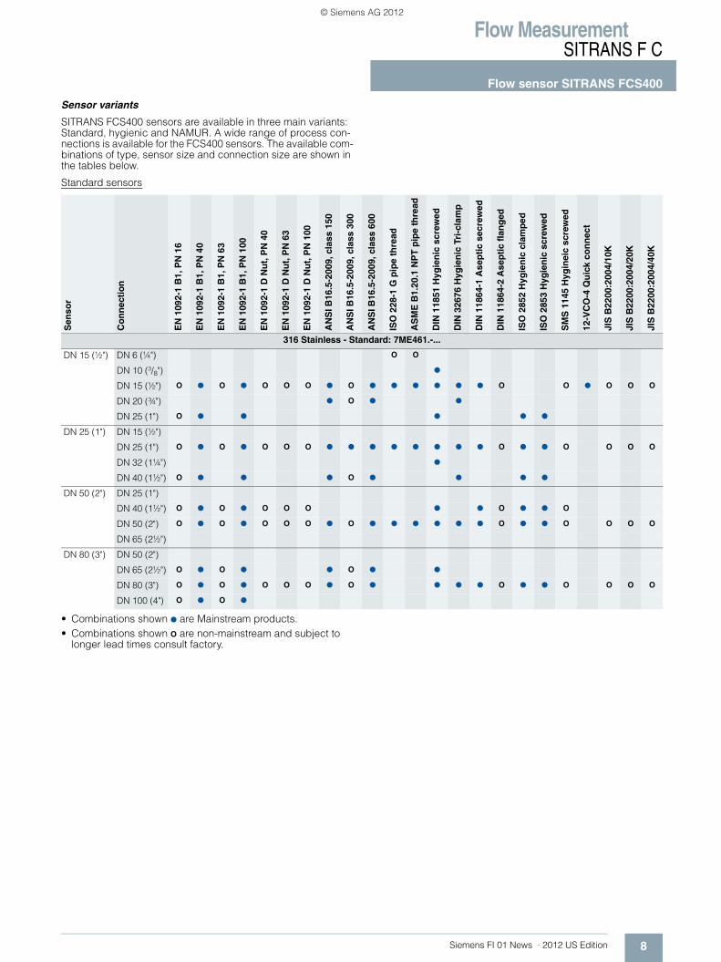
Sensor variants
SITRANS FCS400 sensors are available in three main variants: Standard, hygienic and NAMUR. A wide range of process con-nections is available for the FCS400 sensors. The available com-binations of type, sensor size and connection size are shown in the tables below.
Standard sensors
• Combinations shown ● are Mainstream products. • Combinations shown O are non-mainstream and subject to
longer lead times consult factory.
Sen
sor
Co
nn
ecti
on
EN
109
2-1
B1,
PN
16
EN
109
2-1
B1,
PN
40
EN
109
2-1
B1,
PN
63
EN
109
2-1
B1,
PN
100
EN
109
2-1
D N
ut,
PN
40
EN
109
2-1
D N
ut,
PN
63
EN
109
2-1
D N
ut,
PN
100
AN
SI B
16.5
-200
9, c
lass
150
AN
SI B
16.5
-200
9, c
lass
300
AN
SI B
16.5
-200
9, c
lass
600
ISO
228
-1 G
pip
e th
read
AS
ME
B1.
20.1
NP
T p
ipe
thre
ad
DIN
118
51 H
ygie
nic
scr
ewed
DIN
326
76 H
ygie
nic
Tri
-cla
mp
DIN
118
64-1
Ase
pti
c se
crew
ed
DIN
118
64-2
Ase
pti
c fl
ang
ed
ISO
285
2 H
ygie
nic
cla
mp
ed
ISO
285
3 H
ygie
nic
scr
ewed
SM
S 1
145
Hyg
inei
c sc
rew
ed
12-V
CO
-4 Q
uic
k co
nn
ect
JIS
B22
00:2
004/
10K
JIS
B22
00:2
004/
20K
JIS
B22
00:2
004/
40K
316 Stainless - Standard: 7ME461.-...
DN 15 (½") DN 6 (¼") O O
DN 10 (3/8") ●
DN 15 (½") O ● O ● O O O ● O ● ● ● ● ● ● O O ● O O O
DN 20 (¾") ● O ● ●
DN 25 (1") O ● ● ● ● ●
DN 25 (1") DN 15 (½")
DN 25 (1") O ● O ● O O O ● ● ● ● ● ● ● ● O ● ● O O O O
DN 32 (1¼") ●
DN 40 (1½") O ● ● ● O ● ● ● ●
DN 50 (2") DN 25 (1")
DN 40 (1½") O ● O ● O O O ● ● O ● ● O
DN 50 (2") O ● O ● O O O ● O ● ● ● ● ● ● O ● ● O O O O
DN 65 (2½")
DN 80 (3") DN 50 (2")
DN 65 (2½") O ● O ● ● O ● ●
DN 80 (3") O ● O ● O O O ● O ● ● ● ● O ● ● O O O O
DN 100 (4") O ● O ●
© Siemens AG 2012
Flow MeasurementSITRANS F C
Flow sensor SITRANS FCS400
9 Siemens FI 01 News · 2012 US Edition
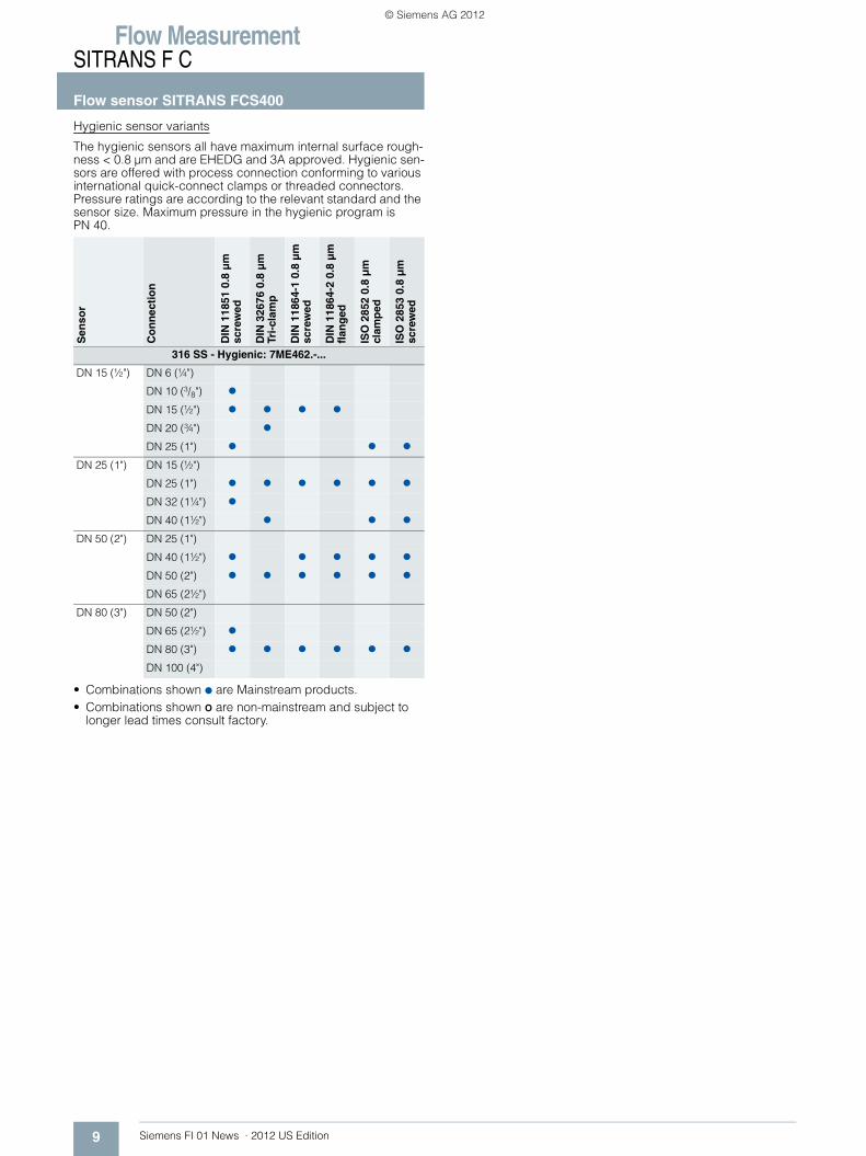
Hygienic sensor variants
The hygienic sensors all have maximum internal surface rough-ness < 0.8 µm and are EHEDG and 3A approved. Hygienic sen-sors are offered with process connection conforming to various international quick-connect clamps or threaded connectors. Pressure ratings are according to the relevant standard and the sensor size. Maximum pressure in the hygienic program is PN 40.
• Combinations shown ● are Mainstream products. • Combinations shown O are non-mainstream and subject to
longer lead times consult factory.
Sen
sor
Co
nn
ecti
on
DIN
118
51 0
.8 μ
m
scre
wed
DIN
326
76 0
.8 μ
m
Tri-
clam
p
DIN
118
64-1
0.8
μm
sc
rew
ed
DIN
118
64-2
0.8
μm
fl
ang
ed
ISO
285
2 0.
8 μ
m
clam
ped
ISO
285
3 0.
8 μ
m
scre
wed
316 SS - Hygienic: 7ME462.-...
DN 15 (½") DN 6 (¼")
DN 10 (3/8") ●
DN 15 (½") ● ● ● ●
DN 20 (¾") ●
DN 25 (1") ● ● ●
DN 25 (1") DN 15 (½")
DN 25 (1") ● ● ● ● ● ●
DN 32 (1¼") ●
DN 40 (1½") ● ● ●
DN 50 (2") DN 25 (1")
DN 40 (1½") ● ● ● ● ●
DN 50 (2") ● ● ● ● ● ●
DN 65 (2½")
DN 80 (3") DN 50 (2")
DN 65 (2½") ●
DN 80 (3") ● ● ● ● ● ●
DN 100 (4")
© Siemens AG 2012
Flow MeasurementSITRANS F C
Flow sensor SITRANS FCS400
10Siemens FI 01 News · 2012 US Edition
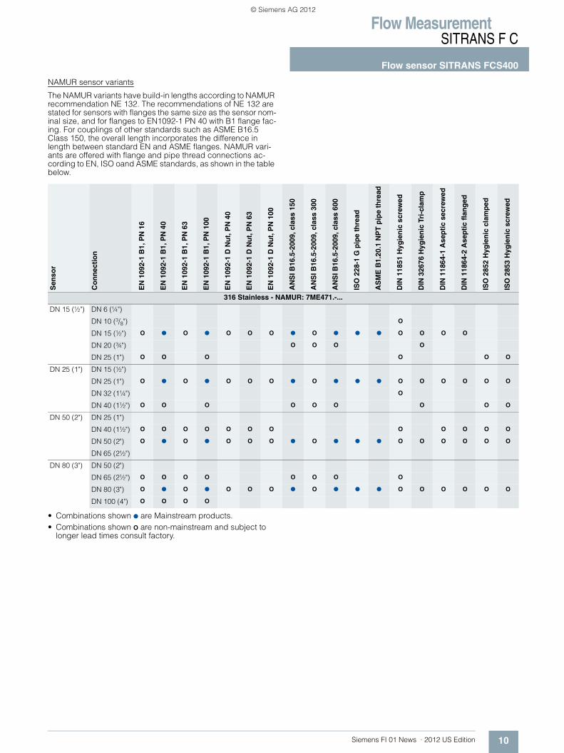
NAMUR sensor variants
The NAMUR variants have build-in lengths according to NAMUR recommendation NE 132. The recommendations of NE 132 are stated for sensors with flanges the same size as the sensor nom-inal size, and for flanges to EN1092-1 PN 40 with B1 flange fac-ing. For couplings of other standards such as ASME B16.5 Class 150, the overall length incorporates the difference in length between standard EN and ASME flanges. NAMUR vari-ants are offered with flange and pipe thread connections ac-cording to EN, ISO oand ASME standards, as shown in the table below.
• Combinations shown ● are Mainstream products. • Combinations shown O are non-mainstream and subject to
longer lead times consult factory.
Sen
sor
Co
nn
ecti
on
EN
109
2-1
B1,
PN
16
EN
109
2-1
B1,
PN
40
EN
109
2-1
B1,
PN
63
EN
109
2-1
B1,
PN
100
EN
109
2-1
D N
ut,
PN
40
EN
109
2-1
D N
ut,
PN
63
EN
109
2-1
D N
ut,
PN
100
AN
SI B
16.5
-200
9, c
lass
150
AN
SI B
16.5
-200
9, c
lass
300
AN
SI B
16.5
-200
9, c
lass
600
ISO
228
-1 G
pip
e th
read
AS
ME
B1.
20.1
NP
T p
ipe
thre
ad
DIN
118
51 H
ygie
nic
scr
ewed
DIN
326
76 H
ygie
nic
Tri
-cla
mp
DIN
118
64-1
Ase
pti
c se
crew
ed
DIN
118
64-2
Ase
pti
c fl
ang
ed
ISO
285
2 H
ygie
nic
cla
mp
ed
ISO
285
3 H
ygie
nic
scr
ewed
316 Stainless - NAMUR: 7ME471.-...
DN 15 (½") DN 6 (¼")
DN 10 (3/8") O
DN 15 (½") O ● O ● O O O ● O ● ● ● O O O O
DN 20 (¾") O O O O
DN 25 (1") O O O O O O
DN 25 (1") DN 15 (½")
DN 25 (1") O ● O ● O O O ● O ● ● ● O O O O O O
DN 32 (1¼") O
DN 40 (1½") O O O O O O O O O
DN 50 (2") DN 25 (1")
DN 40 (1½") O O O O O O O O O O O O
DN 50 (2") O ● O ● O O O ● O ● ● ● O O O O O O
DN 65 (2½")
DN 80 (3") DN 50 (2")
DN 65 (2½") O O O O O O O O
DN 80 (3") O ● O ● O O O ● O ● ● ● O O O O O O
DN 100 (4") O O O O
© Siemens AG 2012
Flow MeasurementSITRANS F C
Flow sensor SITRANS FCS400
11 Siemens FI 01 News · 2012 US Edition
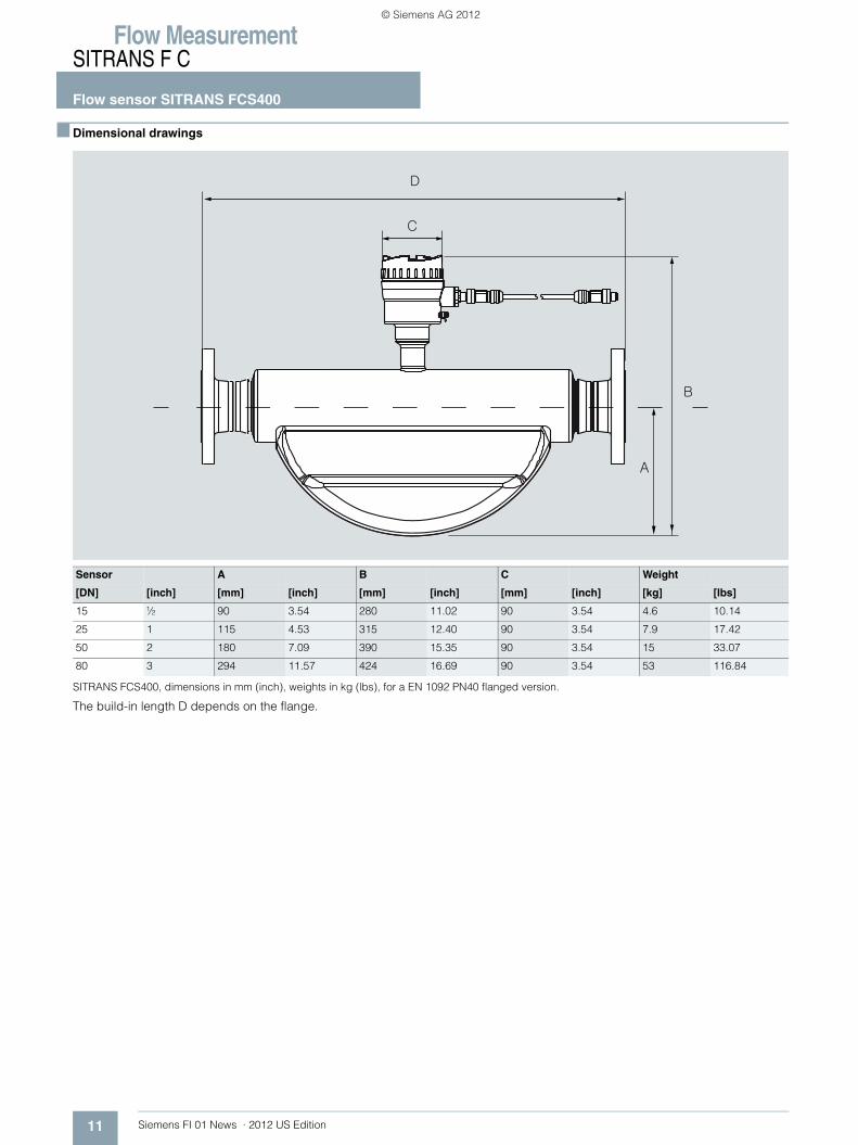
■ Dimensional drawings
SITRANS FCS400, dimensions in mm (inch), weights in kg (lbs), for a EN 1092 PN40 flanged version.
The build-in length D depends on the flange.
Sensor A B C Weight
[DN] [inch] [mm] [inch] [mm] [inch] [mm] [inch] [kg] [lbs]
15 ½ 90 3.54 280 11.02 90 3.54 4.6 10.14
25 1 115 4.53 315 12.40 90 3.54 7.9 17.42
50 2 180 7.09 390 15.35 90 3.54 15 33.07
80 3 294 11.57 424 16.69 90 3.54 53 116.84
© Siemens AG 2012
Flow MeasurementSITRANS F C
Flow sensor SITRANS FCS400
12Siemens FI 01 News · 2012 US Edition
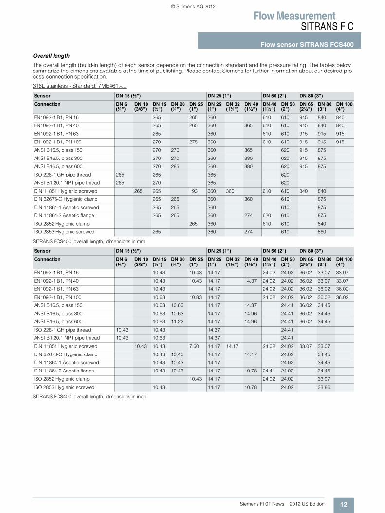
Overall length
The overall length (build-in length) of each sensor depends on the connection standard and the pressure rating. The tables below summarize the dimensions available at the time of publishing. Please contact Siemens for further information about our desired pro-cess connection specification.
316L stainless - Standard: 7ME461.-...
SITRANS FCS400, overall length, dimensions in mm
SITRANS FCS400, overall length, dimensions in inch
Sensor DN 15 (½") DN 25 (1") DN 50 (2") DN 80 (3")
Connection DN 6(¼")
DN 10(3/8")
DN 15(½")
DN 20(¾")
DN 25(1")
DN 25(1")
DN 32(1¼")
DN 40(1½")
DN 40(1½")
DN 50(2")
DN 65(2½")
DN 80(3")
DN 100(4")
EN1092-1 B1, PN 16 265 265 360 610 610 915 840 840
EN1092-1 B1, PN 40 265 265 360 365 610 610 915 840 840
EN1092-1 B1, PN 63 265 360 610 610 915 915 915
EN1092-1 B1, PN 100 270 275 360 610 610 915 915 915
ANSI B16.5, class 150 270 270 360 365 620 915 875
ANSI B16.5, class 300 270 270 360 380 620 915 875
ANSI B16.5, class 600 270 285 360 380 620 915 875
ISO 228-1 GH pipe thread 265 265 365 620
ANSI B1.20.1 NPT pipe thread 265 270 365 620
DIN 11851 Hygienic screwed 265 265 193 360 360 610 610 840 840
DIN 32676-C Hygienic clamp 265 265 360 360 610 875
DIN 11864-1 Aseptic screwed 265 265 360 610 875
DIN 11864-2 Aseptic flange 265 265 360 274 620 610 875
ISO 2852 Hygienic clamp 265 360 610 610 840
ISO 2853 Hygienic screwed 265 360 274 610 860
Sensor DN 15 (½") DN 25 (1") DN 50 (2") DN 80 (3")
Connection DN 6(¼")
DN 10(3/8")
DN 15(½")
DN 20(¾")
DN 25(1")
DN 25(1")
DN 32(1¼")
DN 40(1½")
DN 40(1½")
DN 50(2")
DN 65(2½")
DN 80(3")
DN 100(4")
EN1092-1 B1, PN 16 10.43 10.43 14.17 24.02 24.02 36.02 33.07 33.07
EN1092-1 B1, PN 40 10.43 10.43 14.17 14.37 24.02 24.02 36.02 33.07 33.07
EN1092-1 B1, PN 63 10.43 14.17 24.02 24.02 36.02 36.02 36.02
EN1092-1 B1, PN 100 10.63 10.83 14.17 24.02 24.02 36.02 36.02 36.02
ANSI B16.5, class 150 10.63 10.63 14.17 14.37 24.41 36.02 34.45
ANSI B16.5, class 300 10.63 10.63 14.17 14.96 24.41 36.02 34.45
ANSI B16.5, class 600 10.63 11.22 14.17 14.96 24.41 36.02 34.45
ISO 228-1 GH pipe thread 10.43 10.43 14.37 24.41
ANSI B1.20.1 NPT pipe thread 10.43 10.63 14.37 24.41
DIN 11851 Hygienic screwed 10.43 10.43 7.60 14.17 14.17 24.02 24.02 33.07 33.07
DIN 32676-C Hygienic clamp 10.43 10.43 14.17 14.17 24.02 34.45
DIN 11864-1 Aseptic screwed 10.43 10.43 14.17 24.02 34.45
DIN 11864-2 Aseptic flange 10.43 10.43 14.17 10.78 24.41 24.02 34.45
ISO 2852 Hygienic clamp 10.43 14.17 24.02 24.02 33.07
ISO 2853 Hygienic screwed 10.43 14.17 10.78 24.02 33.86
© Siemens AG 2012
Flow MeasurementSITRANS F C
Flow sensor SITRANS FCS400
13 Siemens FI 01 News · 2012 US Edition
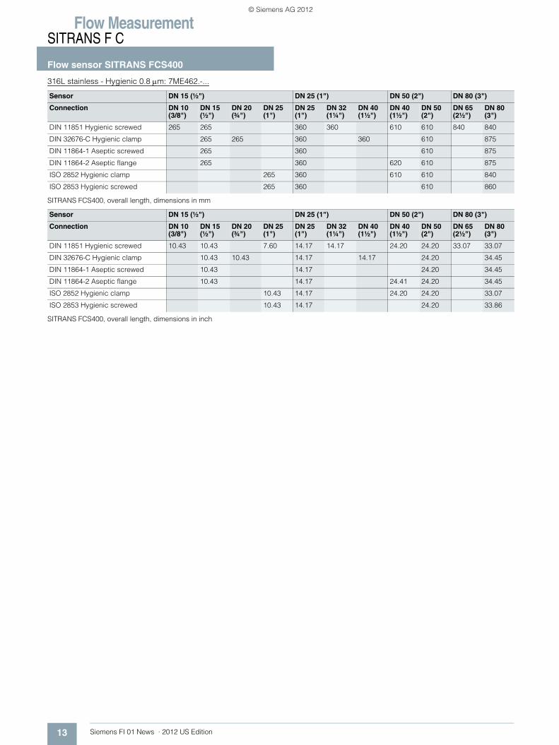
316L stainless - Hygienic 0.8 μm: 7ME462.-...
SITRANS FCS400, overall length, dimensions in mm
SITRANS FCS400, overall length, dimensions in inch
Sensor DN 15 (½") DN 25 (1") DN 50 (2") DN 80 (3")
Connection DN 10(3/8")
DN 15(½")
DN 20(¾")
DN 25(1")
DN 25(1")
DN 32(1¼")
DN 40(1½")
DN 40(1½")
DN 50(2")
DN 65(2½")
DN 80(3")
DIN 11851 Hygienic screwed 265 265 360 360 610 610 840 840
DIN 32676-C Hygienic clamp 265 265 360 360 610 875
DIN 11864-1 Aseptic screwed 265 360 610 875
DIN 11864-2 Aseptic flange 265 360 620 610 875
ISO 2852 Hygienic clamp 265 360 610 610 840
ISO 2853 Hygienic screwed 265 360 610 860
Sensor DN 15 (½") DN 25 (1") DN 50 (2") DN 80 (3")
Connection DN 10(3/8")
DN 15(½")
DN 20(¾")
DN 25(1")
DN 25(1")
DN 32(1¼")
DN 40(1½")
DN 40(1½")
DN 50(2")
DN 65(2½")
DN 80(3")
DIN 11851 Hygienic screwed 10.43 10.43 7.60 14.17 14.17 24.20 24.20 33.07 33.07
DIN 32676-C Hygienic clamp 10.43 10.43 14.17 14.17 24.20 34.45
DIN 11864-1 Aseptic screwed 10.43 14.17 24.20 34.45
DIN 11864-2 Aseptic flange 10.43 14.17 24.41 24.20 34.45
ISO 2852 Hygienic clamp 10.43 14.17 24.20 24.20 33.07
ISO 2853 Hygienic screwed 10.43 14.17 24.20 33.86
© Siemens AG 2012
Flow MeasurementSITRANS F C
Flow sensor SITRANS FCS400
14Siemens FI 01 News · 2012 US Edition
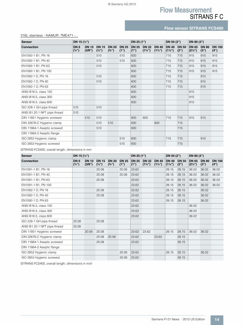
316L stainless - NAMUR: 7ME471.-...
SITRANS FCS400, overall length, dimensions in mm
SITRANS FCS400, overall length, dimensions in inch
Sensor DN 15 (½") DN 25 (1") DN 50 (2") DN 80 (3")
Connection DN 6(¼")
DN 10(3/8")
DN 15(½")
DN 20(¾")
DN 25(1")
DN 25(1")
DN 32(1¼")
DN 40(1½")
DN 40(1½")
DN 50(2")
DN 65(2½")
DN 80(3")
DN 100(4")
EN1092-1 B1, PN 16 510 510 600 715 715 915 915 915
EN1092-1 B1, PN 40 510 510 600 715 715 915 915 915
EN1092-1 B1, PN 63 510 600 715 715 915 915 915
EN1092-1 B1, PN 100 600 715 715 915 915 915
EN1092-1 D, PN 16 510 600 715 715 915
EN1092-1 D, PN 40 510 600 715 715 915
EN1092-1 D, PN 63 600 715 715 915
ANSI B16.5, class 150 600 915
ANSI B16.5, class 300 600 915
ANSI B16.5, class 600 600 915
ISO 228-1 GH pipe thread 510 510
ANSI B1.20.1 NPT pipe thread 510
DIN 11851 Hygienic screwed 510 510 600 600 715 715 915 915
DIN 32676-C Hygienic clamp 510 510 600 600 715
DIN 11864-1 Aseptic screwed 510 600 715
DIN 11864-2 Aseptic flange
ISO 2852 Hygienic clamp 510 600 715 715 915
ISO 2853 Hygienic screwed 510 600 715
Sensor DN 15 (½") DN 25 (1") DN 50 (2") DN 80 (3")
Connection DN 6(¼")
DN 10(3/8")
DN 15(½")
DN 20(¾")
DN 25(1")
DN 25(1")
DN 32(1¼")
DN 40(1½")
DN 40(1½")
DN 50(2")
DN 65(2½")
DN 80(3")
DN 100(4")
EN1091-1 B1, PN 16 20.08 20.08 23.62 28.15 28.15 36.02 36.02 36.02
EN1091-1 B1, PN 40 20.08 20.08 23.62 28.15 28.15 36.02 36.02 36.02
EN1091-1 B1, PN 63 20.08 23.62 28.15 28.15 36.02 36.02 36.02
EN1091-1 B1, PN 100 23.62 28.15 28.15 36.02 36.02 36.02
EN1092-1 D, PN 16 20.08 23.62 28.15 28.15 36.02
EN1092-1 D, PN 40 20.08 23.62 28.15 28.15 36.02
EN1092-1 D, PN 63 23.62 28.15 28.15 36.02
ANSI B16.5, class 150 23.62 36.02
ANSI B16.5, class 300 23.62 36.02
ANSI B16.5, class 600 23.62 36.02
ISO 228-1 GH pipe thread 20.08 20.08
ANSI B1.20.1 NPT pipe thread 20.08
DIN 11851 Hygienic screwed 20.08 20.08 23.62 23.62 28.15 28.15 36.02 36.02
DIN 32676-C Hygienic clamp 20.08 20.08 23.62 23.62 28.15
DIN 11864-1 Aseptic screwed 20.08 23.62 28.15
DIN 11864-2 Aseptic flange
ISO 2852 Hygienic clamp 20.08 23.62 28.15 28.15 36.02
ISO 2853 Hygienic screwed 20.08 23.62 28.15
© Siemens AG 2012
Flow MeasurementSITRANS F C
Flowmeter SITRANS FC430
15 Siemens FI 01 News · 2012 US Edition
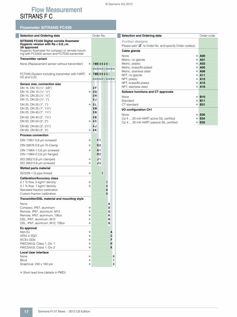
◆ Short lead time (details in PMD)
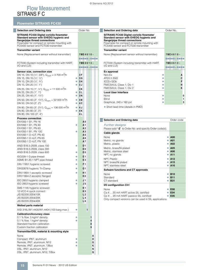
Selection and Ordering data Order No.
SITRANS FC430 Digital coriolis flowmeter Standard sensor with EHEDG hygienic and flange/pipe thread connectionsFlowmeter for compact or remote mounting with FCS400 sensor and FCT030 transmitter
Transmitter variant
None (Replacement sensor without transmitter) 7 ME 4 6 1 0 -
77777 - 7777
FCT030 (System including transmitter with HART, I/O and LUI)
7 ME 4 6 1 3 -
77777 - 7777
Sensor size, connection sizeDN 15, DN 10 (½", 3/8"), Qnom = 3 700 m3/h 3 FDN 15, DN 15 (½", ½") ◆ 3 GDN 15, DN 20 (½", ¾") ◆ 3 HDN 15, DN 25 (½", 1") ◆ 3 J
DN 25, DN 15 (1", ½"), Qnom = 11 500 m3/h 3 KDN 25, DN 25 (1", 1") ◆ 3 LDN 25, DN 40 (1", 1½") ◆ 3 N
DN 50, DN 40 (2", 1½"), Qnom = 52 000 m3/h ◆ 4 BDN 50, DN 50 (2", 2") ◆ 4 C
DN 80, DN 65 (3", 2½"), Qnom = 136 000 m3/h ◆ 4 JDN 80, DN 80 (3", 3") ◆ 4 KDN 80, DN 100 (3", 4") 4 L
Process connectionEN1092-1 B1, PN 16 A 0EN1092-1 B1, PN 40 ◆ A 1EN1092-1 B1, PN 63 A 2EN1092-1 B1, PN 100 ◆ A 3EN1092-1 D nUT, PN 40 A 5EN1092-1 D nUT, PN 63 A 6EN1092-1 D nUT, PN 100 A 7
ANSI B16.5-2009, class 150 ◆ D 1ANSI B16.5-2009, class 300 D 2ANSI B16.5-2009, class 600 ◆ D 3
ISO228-1 G pipe thread ◆ E 1ASME B1.20.1 NPT pipe thread ◆ E 3
DIN 11851 hygienic screwed ◆ F 1
DIN32676 hygienic Tri-Clamp ◆ G 1
DIN11864-1 asceptic screwed ◆ H 1DIN11864-2 asceptic flanged H 2
ISO 2852 hygienic clamped ◆ J 1ISO 2853 hygienic screwed ◆ J 5
SMS 1145 hygienic screwed K 112-VCO-4 quick connect K 5JIS B2200:2004/10K L 2JIS B2220:2004/20K L 4JIS B2220:2004/40K L 6
Wetted parts material
AISI 316L/W1.4435/W1.4404 (100 barg max.) ◆ 1
Calibration/Accuracy class0,1 % flow, 5 kg/m³ density ◆ 10,1 % flow, 1 kg/m³ density ◆ 4Standard fraction calibration 8Custom fraction calibration 9
Transmitter/DSL material & mounting style
None ACompact, IP67, aluminum ◆ DRemote, IP67, aluminum, M12 ◆ GRemote, IP67, aluminum, T/Box ◆ KDSL, IP67, aluminum, M12 NDSL, IP67, aluminum, M12, T/Box Q
Ex approvalNon-Ex ◆ AATEX II 2GD ◆ CIECEx GDb ◆ FFM/CSA/UL Class 1, Div 1 ◆ HFM/CSA/UL Class 1, Div 2 ◆ K
Local User InterfaceNone ◆ 0Blind ◆ 1Graphical, 240 x 160 pxl ◆ 3
Selection and Ordering data Order code
Further designsPlease add "-Z" to Order No. and specify Order code(s).
Cable glands
None ◆ A00Metric, no glands ◆ A01Metric, plastic ◆ A02
Metric, brass/Ni plated ◆ A05Metric, stainless steel ◆ A06NPT, no glands ◆ A11
NPT, Plastic ◆ A12NPT, brass/Ni plated ◆ A15NPT, stainless steel ◆ A16
Sofware functions and CT approvals
None ◆ B10Standard ◆ B11CT standard ◆ B31
I/O configuration Ch1
None ◆ E00Ca 4 ... 20 mA HART active SIL certified ◆ E04Cp 4 ... 20 mA HART passive SIL certified ◆ E05Only compact versions can be used in SIL applications.
Selection and Ordering data Order No.
SITRANS FC430 Digital coriolis flowmeter Standard sensor with EHEDG hygienic and flange/pipe thread connectionsFlowmeter for compact or remote mounting with FCS400 sensor and FCT030 transmitter
Transmitter variant
None (Replacement sensor without transmitter) 7 ME 4 6 1 0 -
77777 - 7777
FCT030 (System including transmitter with HART, I/O and LUI)
7 ME 4 6 1 3 -
77777 - 7777
© Siemens AG 2012

Flow MeasurementSITRANS F C
Flowmeter SITRANS FC430
16Siemens FI 01 News · 2012 US Edition
◆ Short lead time (details in PMD)
Operating instructions for SITRANS FC430
This device is shipped with a Quick Start guide and a CD containingfurther SITRANS F C literature.
All literature is also available for free at: http://www.siemens.com/flowdocumentation
I/O configuration Ch2, Ch3 and Ch4
None F00
aSignal, None, None F40aSignal, aSignal, None ◆ F41aSignal, aSignal, aSignal ◆ F42
aSignal, aSignal, Ia ◆ F43aSignal, aSignal, R ◆ F44aSignal, Ia, None ◆ F45
aSignal, Ia, Ia ◆ F46aSignal, Ia, R ◆ F47aSignal, R, None ◆ F50
aSignal, R, R ◆ F51pSignal, None, None ◆ F60pSignal, pSignal, None ◆ F61
pSignal, pSignal, pSignal ◆ F62pSignal, pSignal, Ip ◆ F63pSignal, pSignal, R ◆ F64
pSignal, Ip, None ◆ F65pSignal, Ip, Ip ◆ F66pSignal, Ip, R ◆ F67
pSignal, R, None ◆ F70pSignal, R, R ◆ F71aSignal, aSignal, pSignal F80
aSignal, aSignal, Ip F81aSignal, pSignal, None F82aSignal, pSignal, pSignal F83
aSignal, pSignal, Ia F84aSignal, pSignal, Ip F85aSignal, pSignal, R F86
aSignal, Ia, Ip F87aSignal, Ip, None F90aSignal, Ip, Ip F91
aSignal, Ip, R F92pSignal, pSignal, Ia F93pSignal, Ia, None F94
pSignal, Ia, Ia F95pSignal, Ia, Ip F96pSignal, Ia, R F97
Notes on I/O configurations:a or p suffix: The I/O module is selected at ordering with either active or passive function. Signal: The output can be selected for Current (0 or 4 to 20 mA), frequency or pulse function in the menu.I: Discrete status input to the flowmeter. Functions are selected in the menu including 'Freeze output', ’Reset totalizer'.R: Relay output for discrete status reporting. Function is selected in the menu, including 'Error', 'High flow warn-ing'.The MLFB structure for FC430 systems must be filled to this level, including "-Z" options A.., B.., E.. and F..
Selection and Ordering data Order code
Add-on options and accessoriesPlease add "-Z" to Order No. and specify Order code(s).
Certificates
Pressure test certificate CRN ◆ C01Pressure test certificate PED ◆ C02Material certificate EN 10204-3.1 ◆ C05
Welding inspection report C07Factory certificate to EN 10204 2.1 ◆ C10Factory certificate to EN 10204 2.2 ◆ C11
Cable
None ◆ L50
5 m (16.4 ft), standard with M12 plugs fitted ◆ L515 m (16.4 ft), standard ◆ L52
10 m (32.8 ft) standard with M12 plugs fitted ◆ L5510 m (32.8 ft), standard ◆ L56
25 m (82 ft), standard with M12 plugs fitted ◆ L5925 m (82 ft), standard ◆ L60
50 m (164 ft), standard with M12 plugs fitted ◆ L6350 m (164 ft), standard ◆ L64
75 m (246 ft), standard with M12 plugs fitted ◆ L6775 m (246 ft), standard ◆ L68
150 m (492 ft), standard with M12 plugs fitted ◆ L71150 m (492 ft), standard ◆ L72
Additional dataPlease add "-Z" to Order No. and specify Order code(s) and plain text.
Tag name
Tag name plate, stainless steel Y17
Transmitter setup
Custom transmitter setup Y20
Customer specific calibration
Customer specific calibration (5 flow x 2 points) Y61Customer specific calibration (10 flow x 1 point) Y62
Description Order No.
• English A5E03361511
• German A5E03651143
• Spanish A5E03651152
• French A5E03651188
• Italian A5E03651190
• Chinese A5E03922773
Selection and Ordering data Order code
© Siemens AG 2012
Flow MeasurementSITRANS F C
Flowmeter SITRANS FC430
17 Siemens FI 01 News · 2012 US Edition
◆ Short lead time (details in PMD)
Selection and Ordering data Order No.
SITRANS FC430 Digital coriolis flowmeter Hygienic version with Ra < 0.8 μm. 3A approvedHygienic flowmeter for compact or remote mount-ing with FCS400 sensor and FCT030 transmitter
Transmitter variant
None (Replacement sensor without transmitter) ◆ 7 ME 4 6 2 0 -
77777 - 7777
FCT030 (System including transmitter with HART, I/O and LUI)
◆ 7 ME 4 6 2 3 -
77777 - 7777
Sensor size, connection sizeDN 15, DN 10 (½", 3/8") 3 FDN 15, DN 15 (½", ½") ◆ 3 GDN 15, DN 20 (½", ¾") 3 HDN 15, DN 25 (½", 1") 3 J
DN 25, DN 25 (1", 1") ◆ 3 LDN 25, DN 25 (1", 1¼") 3 MDN 25, DN 40 (1", 1½") 3 N
DN 50, DN 40 (2", 1½") 4 BDN 50, DN 50 (2", 2") ◆ 4 C
DN 80, DN 65 (3", 2½") 4 JDN 80, DN 80 (3", 3") ◆ 4 K
Process connection
DIN 11851 0,8 µm screwed ◆ F 1
DIN 32676 0,8 µm Tri-Clamp ◆ G 2
DIN 11864-1 0,8 µm screwed ◆ H 1DIN 11864-2 0,8 µm flanged H 2
ISO 2852 0,8 µm clamped ◆ J 1ISO 2853 0,8 µm screwed ◆ J 5
Wetted parts material
ISO228-1 G pipe thread ◆ 1
Calibration/Accuracy class0,1 % flow, 5 kg/m³ density ◆ 10,1 % flow, 1 kg/m³ density ◆ 4Standard fraction calibration 8Custom fraction calibration 9
Transmitter/DSL material and mounting style
None ACompact, IP67, aluminum ◆ DRemote, IP67, aluminum, M12 ◆ GRemote, IP67, aluminum, T/Box ◆ KDSL, IP67, aluminum, M12 ◆ NDSL, IP67, aluminum, M12, T/Box ◆ Q
Ex approvalNon-Ex ◆ AATEX II 2GD ◆ CIECEx GDb ◆ FFM/CSA/UL Class 1, Div 1 ◆ HFM/CSA/UL Class 1, Div 2 ◆ K
Local User InterfaceNone ◆ 0Blind ◆ 1Graphical, 240 x 160 pxl ◆ 3
Selection and Ordering data Order code
Further designsPlease add "-Z" to Order No. and specify Order code(s).
Cable glands
None ◆ A00Metric, no glands ◆ A01Metric, plastic ◆ A02Metric, brass/Ni plated ◆ A05Metric, stainless steel ◆ A06NPT, no glands ◆ A11NPT, plastic ◆ A12NPT, brass/Ni plated ◆ A15NPT, stainless steel ◆ A16
Sofware functions and CT approvals
None ◆ B10Standard ◆ B11CT standard ◆ B31
I/O configuration Ch1
None ◆ E00Ca 4 ... 20 mA HART active SIL certified ◆ E04Cp 4 ... 20 mA HART passive SIL certified ◆ E05
© Siemens AG 2012
Flow MeasurementSITRANS F C
Flowmeter SITRANS FC430
18Siemens FI 01 News · 2012 US Edition
◆ Short lead time (details in PMD)
Operating instructions for SITRANS FC430
This device is shipped with a Quick Start guide and a CD containingfurther SITRANS F C literature.
All literature is also available for free at: http://www.siemens.com/flowdocumentation
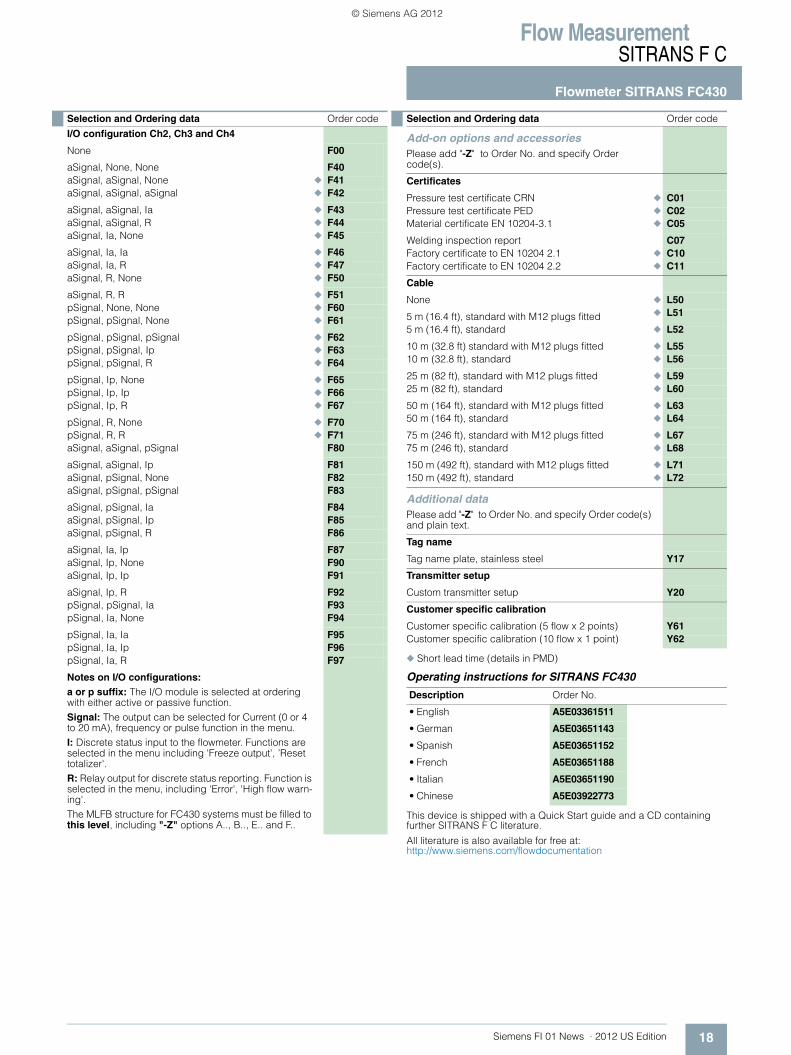
I/O configuration Ch2, Ch3 and Ch4
None F00
aSignal, None, None F40aSignal, aSignal, None ◆ F41aSignal, aSignal, aSignal ◆ F42
aSignal, aSignal, Ia ◆ F43aSignal, aSignal, R ◆ F44aSignal, Ia, None ◆ F45
aSignal, Ia, Ia ◆ F46aSignal, Ia, R ◆ F47aSignal, R, None ◆ F50
aSignal, R, R ◆ F51pSignal, None, None ◆ F60pSignal, pSignal, None ◆ F61
pSignal, pSignal, pSignal ◆ F62pSignal, pSignal, Ip ◆ F63pSignal, pSignal, R ◆ F64
pSignal, Ip, None ◆ F65pSignal, Ip, Ip ◆ F66pSignal, Ip, R ◆ F67
pSignal, R, None ◆ F70pSignal, R, R ◆ F71aSignal, aSignal, pSignal F80
aSignal, aSignal, Ip F81aSignal, pSignal, None F82aSignal, pSignal, pSignal F83
aSignal, pSignal, Ia F84aSignal, pSignal, Ip F85aSignal, pSignal, R F86
aSignal, Ia, Ip F87aSignal, Ip, None F90aSignal, Ip, Ip F91
aSignal, Ip, R F92pSignal, pSignal, Ia F93pSignal, Ia, None F94
pSignal, Ia, Ia F95pSignal, Ia, Ip F96pSignal, Ia, R F97
Notes on I/O configurations:a or p suffix: The I/O module is selected at ordering with either active or passive function. Signal: The output can be selected for Current (0 or 4 to 20 mA), frequency or pulse function in the menu.I: Discrete status input to the flowmeter. Functions are selected in the menu including 'Freeze output', ’Reset totalizer'.R: Relay output for discrete status reporting. Function is selected in the menu, including 'Error', 'High flow warn-ing'.The MLFB structure for FC430 systems must be filled to this level, including "-Z" options A.., B.., E.. and F..
Selection and Ordering data Order code
Add-on options and accessoriesPlease add "-Z" to Order No. and specify Order code(s).
Certificates
Pressure test certificate CRN ◆ C01Pressure test certificate PED ◆ C02Material certificate EN 10204-3.1 ◆ C05
Welding inspection report C07Factory certificate to EN 10204 2.1 ◆ C10Factory certificate to EN 10204 2.2 ◆ C11
Cable
None ◆ L50
5 m (16.4 ft), standard with M12 plugs fitted ◆ L51
5 m (16.4 ft), standard ◆ L52
10 m (32.8 ft) standard with M12 plugs fitted ◆ L5510 m (32.8 ft), standard ◆ L56
25 m (82 ft), standard with M12 plugs fitted ◆ L5925 m (82 ft), standard ◆ L60
50 m (164 ft), standard with M12 plugs fitted ◆ L6350 m (164 ft), standard ◆ L64
75 m (246 ft), standard with M12 plugs fitted ◆ L6775 m (246 ft), standard ◆ L68
150 m (492 ft), standard with M12 plugs fitted ◆ L71150 m (492 ft), standard ◆ L72
Additional dataPlease add "-Z" to Order No. and specify Order code(s) and plain text.
Tag name
Tag name plate, stainless steel Y17
Transmitter setup
Custom transmitter setup Y20
Customer specific calibration
Customer specific calibration (5 flow x 2 points) Y61Customer specific calibration (10 flow x 1 point) Y62
Description Order No.
• English A5E03361511
• German A5E03651143
• Spanish A5E03651152
• French A5E03651188
• Italian A5E03651190
• Chinese A5E03922773
Selection and Ordering data Order code
© Siemens AG 2012
Flow MeasurementSITRANS F C
Flowmeter SITRANS FC430
19 Siemens FI 01 News · 2012 US Edition
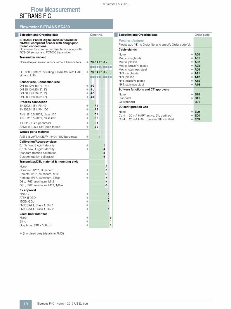
◆ Short lead time (details in PMD)
Selection and Ordering data Order No.
SITRANS FC430 Digital coriolis flowmeter NAMUR compliant sensor with flange/pipe thread connectionsFlowmeter for compact or remote mounting with FCS400 sensor and FCT030 transmitter
Transmitter variant
None (Replacement sensor without transmitter) ◆ 7 ME 4 7 1 0 -
77777 - 7777
FCT030 (System including transmitter with HART, I/O and LUI)
◆ 7 ME 4 7 1 3 -
77777 - 7777
Sensor size, Connection sizeDN 15, DN 15 (½", ½") ◆ 3 GDN 25, DN 25 (1", 1") ◆ 3 LDN 50, DN 50 (2", 2") ◆ 4 CDN 80, DN 80 (3", 3") ◆ 4 K
Process connectionEN1092-1 B1, PN 40 ◆ A 1EN1092-1 B1, PN 100 ◆ A 3
ANSI B16.5-2009, class 150 ◆ D 1ANSI B16.5-2009, class 600 ◆ D 3
ISO228-1 G pipe thread ◆ E 1ASME B1.20.1 NPT pipe thread ◆ E 3
Wetted parts material
AISI 316L/W1.4435/W1.4404 (100 barg max.) ◆ 1
Calibration/Accuracy class0,1 % flow, 5 kg/m³ density ◆ 10,1 % flow, 1 kg/m³ density ◆ 4Standard fraction calibration 8Custom fraction calibration 9
Transmitter/DSL material & mounting style
None ACompact, IP67, aluminum ◆ DRemote, IP67, aluminum, M12 ◆ GRemote, IP67, aluminum, T/Box ◆ KDSL, IP67, aluminum, M12 NDSL, IP67, aluminum, M12, T/Box Q
Ex approvalNon-Ex ◆ AATEX II 2GD ◆ CIECEx GDb ◆ FFM/CSA/UL Class 1, Div 1 ◆ HFM/CSA/UL Class 1, Div 2 ◆ K
Local User InterfaceNone ◆ 0Blind ◆ 1Graphical, 240 x 160 pxl ◆ 3
Selection and Ordering data Order code
Further designsPlease add "-Z" to Order No. and specify Order code(s).
Cable glands
None ◆ A00Metric, no glands ◆ A01Metric, plastic ◆ A02Metric, brass/Ni plated ◆ A05Metric, stainless steel ◆ A06NPT, no glands ◆ A11NPT, plastic ◆ A12NPT, brass/Ni plated ◆ A15NPT, stainless steel ◆ A16
Sofware functions and CT approvals
None ◆ B10Standard ◆ B11CT standard B31
I/O configuration Ch1
None ◆ E00Ca 4 ... 20 mA HART active, SIL certified ◆ E04Cp 4 ... 20 mA HART passive, SIL certified ◆ E05
© Siemens AG 2012

Flow MeasurementSITRANS F C
Flowmeter SITRANS FC430
20Siemens FI 01 News · 2012 US Edition
◆ Short lead time (details in PMD)
Operating instructions for SITRANS FC430
This device is shipped with a Quick Start guide and a CD containingfurther SITRANS F C literature.
All literature is also available for free at: http://www.siemens.com/flowdocumentation
I/O configuration Ch2, Ch3 and Ch4
None F00
aSignal, None, None F40aSignal, aSignal, None ◆ F41aSignal, aSignal, aSignal ◆ F42
aSignal, aSignal, Ia ◆ F43aSignal, aSignal, R ◆ F44aSignal, Ia, None ◆ F45
aSignal, Ia, Ia ◆ F46aSignal, Ia, R ◆ F47aSignal, R, None ◆ F50
aSignal, R, R ◆ F51pSignal, None, None ◆ F60pSignal, pSignal, None ◆ F61
pSignal, pSignal, pSignal ◆ F62pSignal, pSignal, Ip ◆ F63pSignal, pSignal, R ◆ F64
pSignal, Ip, None ◆ F65pSignal, Ip, Ip ◆ F66pSignal, Ip, R ◆ F67
pSignal, R, None ◆ F70pSignal, R, R ◆ F71aSignal, aSignal, pSignal F80
aSignal, aSignal, Ip F81aSignal, pSignal, None F82aSignal, pSignal, pSignal F83
aSignal, pSignal, Ia F84aSignal, pSignal, Ip F85aSignal, pSignal, R F86
aSignal, Ia, Ip F87aSignal, Ip, None F90aSignal, Ip, Ip F91
aSignal, Ip, R F92pSignal, pSignal, Ia F93pSignal, Ia, None F94
pSignal, Ia, Ia F95pSignal, Ia, Ip F96pSignal, Ia, R F97
Notes on I/O configurations:a or p suffix: The I/O module is selected at ordering with either active or passive function. Signal: The output can be selected for Current (0 or 4 to 20 mA), frequency or pulse function in the menu.I: Discrete status input to the flowmeter. Functions are selected in the menu including 'Freeze output', ’Reset totalizer'.R: Relay output for discrete status reporting. Function is selected in the menu, including 'Error', 'High flow warn-ing'.The MLFB structure for FC430 systems must be filled to this level, including "-Z" options A..., B..., E... and F...
Selection and Ordering data Order code
Add-on options and accessoriesPlease add "-Z" to Order No. and specify Order code(s).
Certificates
Pressure test certificate CRN ◆ C01Pressure test certificate PED ◆ C02Material certificate EN 10204-3.1 ◆ C05
Welding inspection report C07Factory certificate to EN 10204 2.1 ◆ C10Factory certificate to EN 10204 2.2 ◆ C11
Cable
None ◆ L50
5 m (16.4 ft), standard with M12 plugs fitted ◆ L51
5 m (16.4 ft), standard ◆ L52
10 m (32.8 ft) standard with M12 plugs fitted ◆ L5510 m (32.8 ft), standard ◆ L56
25 m (82 ft), standard with M12 plugs fitted ◆ L5925 m (82 ft), standard ◆ L60
50 m (164 ft), standard with M12 plugs fitted ◆ L6350 m (164 ft), standard ◆ L64
75 m (246 ft), standard with M12 plugs fitted ◆ L6775 m (246 ft), standard ◆ L68
150 m (492 ft), standard with M12 plugs fitted ◆ L71150 m (492 ft), standard ◆ L72
Additional dataPlease add "-Z" to Order No. and specify Order code(s) and plain text.
Tag name
Tag name plate, stainless steel Y17
Transmitter setup
Custom transmitter setup Y20
Customer specific calibration
Customer specific calibration (5 flow x 2 points) Y61Customer specific calibration (10 flow x 1 point) Y62
Description Order No.
• English A5E03361511
• German A5E03651143
• Spanish A5E03651152
• French A5E03651188
• Italian A5E03651190
• Chinese A5E03922773
Selection and Ordering data Order code
© Siemens AG 2012
Flow MeasurementSITRANS F C
Flowmeter SITRANS FC430
21 Siemens FI 01 News · 2012 US Edition
◆ Short lead time (details in PMD)
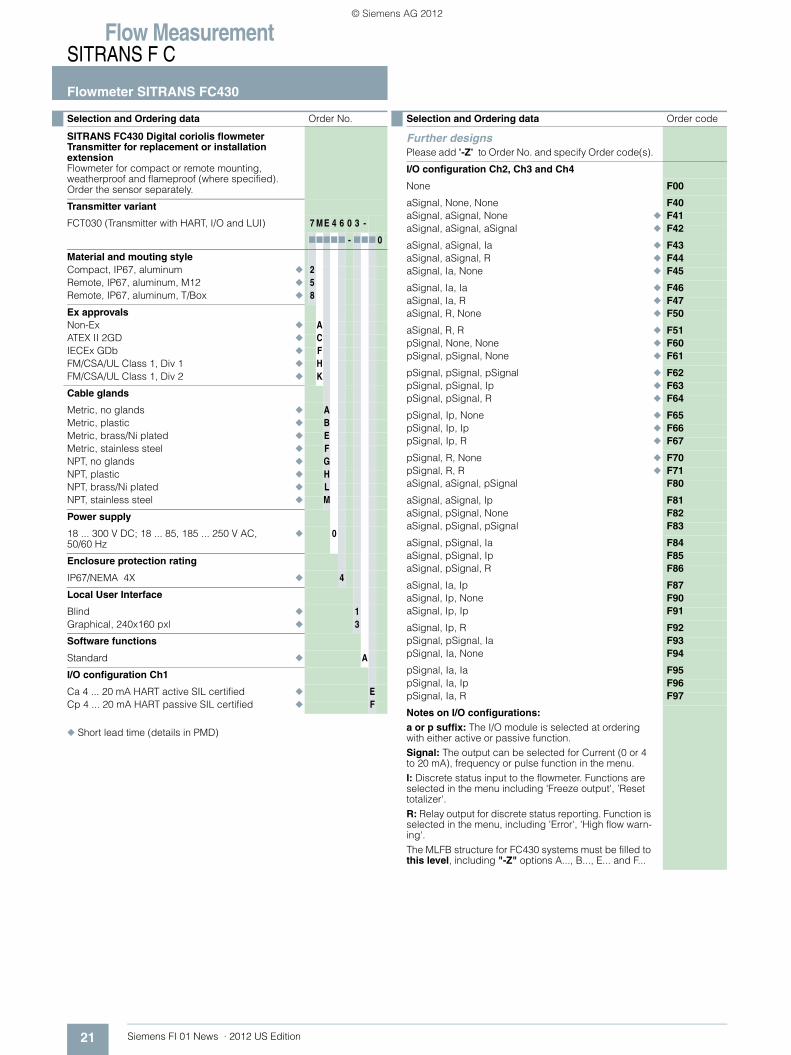
Selection and Ordering data Order No.
SITRANS FC430 Digital coriolis flowmeter Transmitter for replacement or installation extensionFlowmeter for compact or remote mounting, weatherproof and flameproof (where specified). Order the sensor separately.
Transmitter variant
FCT030 (Transmitter with HART, I/O and LUI) 7 ME 4 6 0 3 -
77777 - 777 0
Material and mouting styleCompact, IP67, aluminum ◆ 2Remote, IP67, aluminum, M12 ◆ 5Remote, IP67, aluminum, T/Box ◆ 8
Ex approvalsNon-Ex ◆ AATEX II 2GD ◆ CIECEx GDb ◆ FFM/CSA/UL Class 1, Div 1 ◆ HFM/CSA/UL Class 1, Div 2 ◆ K
Cable glands
Metric, no glands ◆ AMetric, plastic ◆ BMetric, brass/Ni plated ◆ EMetric, stainless steel ◆ FNPT, no glands ◆ GNPT, plastic ◆ HNPT, brass/Ni plated ◆ LNPT, stainless steel ◆ M
Power supply
18 ... 300 V DC; 18 ... 85, 185 ... 250 V AC, 50/60 Hz
◆ 0
Enclosure protection rating
IP67/NEMA 4X ◆ 4
Local User Interface
Blind ◆ 1Graphical, 240x160 pxl ◆ 3
Software functions
Standard ◆ A
I/O configuration Ch1
Ca 4 ... 20 mA HART active SIL certified ◆ ECp 4 ... 20 mA HART passive SIL certified ◆ F
Selection and Ordering data Order code
Further designsPlease add "-Z" to Order No. and specify Order code(s).
I/O configuration Ch2, Ch3 and Ch4
None F00
aSignal, None, None F40aSignal, aSignal, None ◆ F41aSignal, aSignal, aSignal ◆ F42
aSignal, aSignal, Ia ◆ F43aSignal, aSignal, R ◆ F44aSignal, Ia, None ◆ F45
aSignal, Ia, Ia ◆ F46aSignal, Ia, R ◆ F47aSignal, R, None ◆ F50
aSignal, R, R ◆ F51pSignal, None, None ◆ F60pSignal, pSignal, None ◆ F61
pSignal, pSignal, pSignal ◆ F62pSignal, pSignal, Ip ◆ F63pSignal, pSignal, R ◆ F64
pSignal, Ip, None ◆ F65pSignal, Ip, Ip ◆ F66pSignal, Ip, R ◆ F67
pSignal, R, None ◆ F70pSignal, R, R ◆ F71aSignal, aSignal, pSignal F80
aSignal, aSignal, Ip F81aSignal, pSignal, None F82aSignal, pSignal, pSignal F83
aSignal, pSignal, Ia F84aSignal, pSignal, Ip F85aSignal, pSignal, R F86
aSignal, Ia, Ip F87aSignal, Ip, None F90aSignal, Ip, Ip F91
aSignal, Ip, R F92pSignal, pSignal, Ia F93pSignal, Ia, None F94
pSignal, Ia, Ia F95pSignal, Ia, Ip F96pSignal, Ia, R F97
Notes on I/O configurations:a or p suffix: The I/O module is selected at ordering with either active or passive function. Signal: The output can be selected for Current (0 or 4 to 20 mA), frequency or pulse function in the menu.I: Discrete status input to the flowmeter. Functions are selected in the menu including 'Freeze output', ’Reset totalizer'.R: Relay output for discrete status reporting. Function is selected in the menu, including 'Error', 'High flow warn-ing'.The MLFB structure for FC430 systems must be filled to this level, including "-Z" options A..., B..., E... and F...
© Siemens AG 2012
Flow MeasurementSITRANS F C
Flowmeter SITRANS FC430
22Siemens FI 01 News · 2012 US Edition
◆ Short lead time (details in PMD)
Operating instructions for SITRANS FC430
This device is shipped with a Quick Start guide and a CD containingfurther SITRANS F C literature.
All literature is also available for free at: http://www.siemens.com/flowdocumentation
Add-on options and accessoriesPlease add "-Z" to Order No. and specify Order code(s).
CertificatesFactory certificate to EN 10204 2.1 ◆ C10Factory certificate to EN 10204 2.2 ◆ C11
Cable
None ◆ L50
5 m (16.4 ft), standard with M12 plugs fitted ◆ L515 m (16.4 ft), standard ◆ L52
10 m (32.8 ft) standard with M12 plugs fitted ◆ L5510 m (32.8 ft), standard ◆ L56
25 m (82 ft), standard with M12 plugs fitted ◆ L5925 m (82 ft), standard ◆ L60
50 m (164 ft), standard with M12 plugs fitted ◆ L6350 m (164 ft), standard ◆ L64
75 m (246 ft), standard with M12 plugs fitted ◆ L6775 m (246 ft), standard ◆ L68
150 m (492 ft), standard with M12 plugs fitted ◆ L71150 m (492 ft), standard ◆ L72
Additional dataPlease add "-Z" to Order No. and specify Order code(s) and plain text.
Tag name
Tag name plate, stainless steel Y17
Transmitter setup
Custom transmitter setup Y20
Description Order No.
• English A5E03361511
• German A5E03651143
• Spanish A5E03651152
• French A5E03651188
• Italian A5E03651190
• Chinese A5E03922773
Selection and Ordering data Order code
© Siemens AG 2012
Flow MeasurementSITRANS F C
Flowmeter SITRANS FC430
23 Siemens FI 01 News · 2012 US Edition
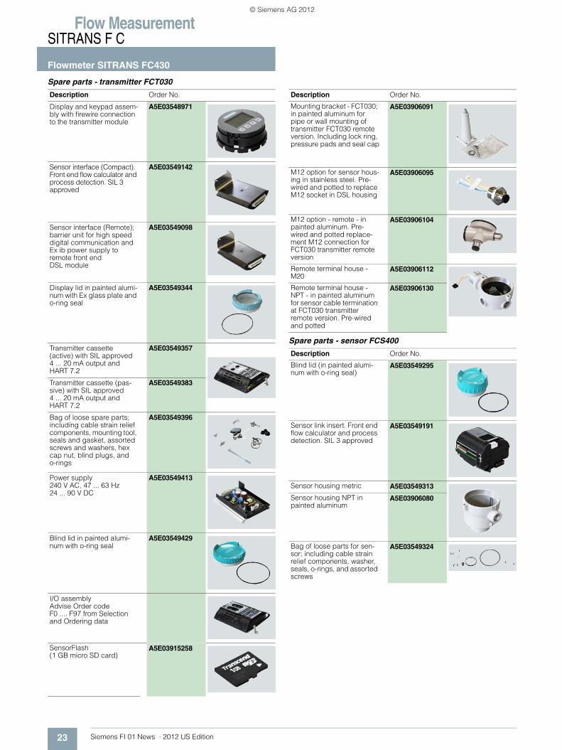
Spare parts - transmitter FCT030
Spare parts - sensor FCS400
Description Order No.
Display and keypad assem-bly with firewire connection to the transmitter module
A5E03548971
Sensor interface (Compact). Front end flow calculator and process detection. SIL 3 approved
A5E03549142
Sensor interface (Remote); barrier unit for high speed digital communication and Ex ib power supply to remote front end DSL module
A5E03549098
Display lid in painted alumi-num with Ex glass plate and o-ring seal
A5E03549344
Transmitter cassette (active) with SIL approved 4 ... 20 mA output and HART 7.2
A5E03549357
Transmitter cassette (pas-sive) with SIL approved 4 ... 20 mA output and HART 7.2
A5E03549383
Bag of loose spare parts; including cable strain relief components, mounting tool, seals and gasket, assorted screws and washers, hex cap nut, blind plugs, and o-rings
A5E03549396
Power supply240 V AC, 47 ... 63 Hz24 ... 90 V DC
A5E03549413
Blind lid in painted alumi-num with o-ring seal
A5E03549429
I/O assemblyAdvise Order code F0 .... F97 from Selection and Ordering data
SensorFlash (1 GB micro SD card)
A5E03915258
Mounting bracket - FCT030; in painted aluminum for pipe or wall mounting of transmitter FCT030 remote version. Including lock ring, pressure pads and seal cap
A5E03906091
M12 option for sensor hous-ing in stainless steel. Pre-wired and potted to replace M12 socket in DSL housing
A5E03906095
M12 option - remote - in painted aluminum. Pre-wired and potted replace-ment M12 connection for FCT030 transmitter remote version
A5E03906104
Remote terminal house - M20
A5E03906112
Remote terminal house - NPT - in painted aluminum for sensor cable termination at FCT030 transmitter remote version. Pre-wired and potted
A5E03906130
Description Order No.
Blind lid (in painted alumi-num with o-ring seal)
A5E03549295
Sensor link insert. Front end flow calculator and process detection. SIL 3 approved
A5E03549191
Sensor housing metric A5E03549313
Sensor housing NPT in painted aluminum
A5E03906080
Bag of loose parts for sen-sor; including cable strain relief components, washer, seals, o-rings, and assorted screws
A5E03549324
Description Order No.
© Siemens AG 2012
Flow MeasurementSITRANS F C
Flowmeter SITRANS FC430
24Siemens FI 01 News · 2012 US Edition
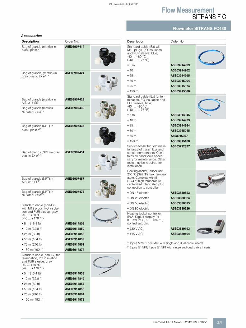
Accessories
1) 2 pcs M20; 1 pce M25 with single and dual cable inserts2) 2 pcs ½" NPT; 1 pce ½" NPT with single and dual cable inserts
Description Order No.
Bag of glands (metric) in black plastic1)
A5E03907414
Bag of glands, (metric) in gray plastic Ex e/i1)
A5E03907424
Bag of glands (metric) in AISI 316 SS1)
A5E03907429
Bag of glands (metric) NiPlatedBrass1)
A5E03907430
Bag of glands (NPT) in black plastic2)
A5E03907435
Bag of glands (NPT) in gray plastic Ex e/i2)
A5E03907451
Bag of glands (NPT) in AISI 316 SS2)
A5E03907467
Bag of glands (NPT) in NiPlatedBrass2)
A5E03907473
Standard cable (non-Ex) with M12 plugs, PO insula-tion and PUR sleeve, gray,-40 ... +80 °C (-40 ... +176 °F)
• 5 m (16.4 ft) A5E03914805
• 10 m (32.8 ft) A5E03914850
• 25 m (82 ft) A5E03914853
• 50 m (164 ft) A5E03914859
• 75 m (246 ft) A5E03914861
• 150 m (492 ft) A5E03914874
Standard cable (non-Ex) for termination, PO insulation and PUR sleeve, gray, -40 ... +80 °C (-40 ... +176 °F)
• 5 m (16.4 ft) A5E03914833
• 10 m (32.8 ft) A5E03914849
• 25 m (82 ft) A5E03914854
• 50 m (164 ft) A5E03914856
• 75 m (246 ft) A5E03914864
• 150 m (492 ft) A5E03914873
Standard cable (Ex) with M12 plugs, PO insulation and PUR sleeve, blue,-40 ... +80 °C (-40 ... +176 °F)
• 5 m A5E03914929
• 10 m A5E03914962
• 25 m A5E03914995
• 50 m A5E03915004
• 75 m A5E03915074
• 150 m A5E03915088
Standard cable (Ex) for ter-mination, PO insulation and PUR sleeve, blue, -40 ... +80 °C (-40 ... +176 °F)
• 5 m A5E03914945
• 10 m A5E03914973
• 25 m A5E03914984
• 50 m A5E03915015
• 75 m A503915057
• 150 m A5E03915100
Service toolkit for field main-tenance of transmitter and sensor components. Con-tains all hand tools neces-sary for maintenance. Other tools may be required for installation.
A5E03722877
Heating Jacket, indoor use, 200 °C (392 °F) max. temper-ature. Complete with 5 m (16.4 ft) high temperature cable fitted. Dedicated plug connection to controller
• DN 15 electric A5E03830623
• DN 25 electric A5E03830624
• DN 50 electric A5E03830625
• DN 80 electric A5E03830626
Heating jacket controller, IP65. Digital display for 0 ... 200 °C (32 .. 392 °F) control setpoint
• 230 V AC A5E03839193
• 115 V AC A5E03839194
Description Order No.
© Siemens AG 2012
Flow MeasurementSITRANS F C
Flowmeter SITRANS FC430
25 Siemens FI 01 News · 2012 US Edition
Description Dimension Order No.
Mating parts for hygienic fittings DIN 11851Includes:• 2 unions• 2 mating parts (for welding in)• 2 EPDM gaskets
DN 10 FDK-085U1016
DN 15 FDK-085U1017
DN 25 FDK-085U1019
DN 32 FDK-085U1020
DN 40 FDK-085U1021
DN 50 FDK-085U1022
DN 65 FDK-085U1023
Mating parts for hygienic clamp ISO 2852Includes:• 2 clamps• 2 mating parts• 2 EPDM gaskets
25 mm FDK-085U1029
40 mm FDK-085U1031
50 mm FDK-085U1032
2 EPDM gaskets with collar for mounting set DIN 11851
DN 10 FDK-085U1006
DN 15 FDK-085U1007
DN 25 FDK-085U1009
DN 32 FDK-085U1010
DN 40 FDK-085U1011
DN 50 FDK-085U1012
DN 65 FDK-085U1013
© Siemens AG 2012
Recommended