Floor gratings Gitterroste, Grate
Floor gratings
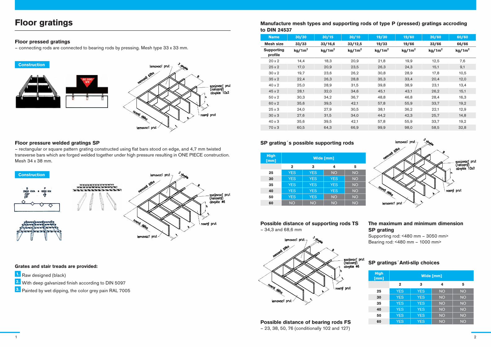
Floor pressed gratings – connecting rods are connected to bearing rods by pressing. Mesh type 33 x 33 mm.
Construction
Floor pressure welded gratings SP – rectangular or square pattern grating constructed using flat bars stood on edge, and 4,7 mm twisted transverse bars which are forged welded together under high pressure resulting in ONE PIECE construction. Mesh 34 x 38 mm.
Grates and stair treads are provided:
1. Raw designed (black) 2. With deep galvanized finish according to DIN 50973. Painted by wet dipping, the color grey pain RAL 7005
Manufacture mesh types and supporting rods of type P (pressed) gratings accroding to DIN 24537
Name 30/30 30/15 30/10 19/30 19/60 30/60 60/60
Mesh size 33/33 33/16,6 33/12,5 19/33 19/66 33/66 66/66
Supporting profile
kg/1m2 kg/1m2 kg/1m2 kg/1m2 kg/1m2 kg/1m2 kg/1m2
20 x 2 14,4 18,3 20,9 21,8 19,9 12,5 7,6
25 x 2 17,0 20,9 23,5 26,3 24,3 15,1 9,1
30 x 2 19,7 23,6 26,2 30,8 28,9 17,8 10,5
35 x 2 22,4 26,3 28,8 35,3 33,4 20,4 12,0
40 x 2 25,0 28,9 31,5 39,8 38,9 23,1 13,4
45 x 2 28,1 32,0 34,6 45,1 43,1 26,2 15,1
50 x 2 30,3 34,2 36,7 48,8 46,8 28,4 16,3
60 x 2 35,6 39,5 42,1 57,8 55,9 33,7 19,2
25 x 3 24,0 27,9 30,5 38,1 36,2 22,1 12,9
30 x 3 27,6 31,5 34,0 44,2 42,3 25,7 14,8
40 x 3 35,6 39,5 42,1 57,8 55,9 33,7 19,2
70 x 3 60,5 64,3 66,9 99,9 98,0 58,5 32,8
SP grating´s possible supporting rods
High [mm]
Wide [mm]
2 3 4 5
25 YES YES NO NO
30 YES YES YES NO
35 YES YES YES NO
40 YES YES YES NO
50 YES YES NO NO
60 NO NO NO NO
Possible distance of supporting rods TS– 34,3 and 68,6 mm
Possible distance of bearing rods FS– 23, 38, 50, 76 (conditionally 102 and 127)
SP gratings´Anti-slip choices
High [mm]
Wide [mm]
2 3 4 5
25 YES YES NO NO
30 YES YES NO NO
35 YES YES NO NO
40 YES YES NO NO
50 YES YES NO NO
60 YES YES NO NO
The maximum and minimum dimension SP gratingSupporting rod: <480 mm – 3050 mm>Bearing rod: <480 mm – 1000 mm>
Construction
1 2
Load of gratings with 30 x 30 mm mesh
® Bearing rod h x t [mm] * Distancec of support [mm]
Q Uniform load in kN/m2 f Deflection in mm from load q
P Point load in kN in the centre of the grating 200 x 200 mm fl Deflection in mm from P
® * 500 600 700 800 900 1000 1100 1200 1300 1400 1500
20 x 2
q 18,45 12,80 9,40 7,20 5,70
f 2,0 2,9 3,9 5,1 6,4
P 1,80 1,45 1,20 1,00 0,90
fl 1,8 2,6 3,5 4,5 5,7
25 x 2
q 28,80 20,00 14,70 11,25 8,90 7,20 5,95 5,00
f 1,6 2,3 3,1 4,1 5,1 6,3 7,7 9,1
P 2,75 2,20 1,85 1,60 1,40 1,25 1,10 1,00
fl 1,5 2,1 2,8 3,6 4,5 5,5 6,7 6,9
30 x 2
q 41,50 28,80 21,15 16,20 12,80 10,35 8,55 7,20 6,15 5,30
f 1,3 1,9 2,6 3,4 4,3 5,3 6,4 7,6 8,9 10,4
P 3,95 3,20 2,65 2,25 2,00 1,75 1,60 1,45 1,30 1,20
fl 1,2 1,7 2,3 3,0 3,8 4,6 5,5 6,6 7,7 8,8
40 x 2
q 73,75 51,20 37,60 28,80 22,75 18,45 15,25 12,80 10,90 9,40 8,20
f 1,0 1,4 1,9 2,5 3,2 4,0 4,8 5,7 6,7 7,8 8,9
P 6,90 5,55 4,60 3,95 3,45 3,10 2,75 2,50 2,30 2,15 1,98
fl 0,9 1,3 1,7 2,3 2,8 3,5 4,2 4,9 5,7 6,6 7,6
20 x 3
q 27,65 19,2 14,10 10,80 8,55 6,90 5,70
f 2,0 2,9 3,9 5,1 6,4 7,9 9,6
P 2,70 2,15 1,80 1,55 1,35 1,20 1,05
fl 1,8 2,6 3,5 4,5 5,7 6,9 8,3
25 x 3
q 43,20 30,00 22,05 16,90 13,35 10,80 8,90 7,50 6,40 5,50
f 1,6 2,3 3,1 4,1 5,1 6,4 7,7 9,1 10,7 12,4
P 4,15 3,35 2,80 2,40 2,10 1,85 1,65 1,50 1,40 1,30
fl 4,15 3,35 2,80 2,40 2,10 1,85 1,65 1,50 1,40 1,30
30 x 3
q 62,20 43,20 31,75 24,30 19,20 15,55 12,85 10,80 9,20 7,95 6,90
f 1,3 1,9 2,6 3,4 4,3 5,3 6,4 7,6 8,9 10,4 11,9
P 5,95 4,75 3,95 3,40 3,00 2,65 2,40 2,15 2,00 1,85 1,70
fl 1,2 1,7 2,3 3,0 3,8 4,6 5,5 6,6 7,7 8,8 10,1
40 x 3
q 110,0 76,80 56,45 43,20 34,15 27,65 22,85 19,20 16,35 14,10 12,30
f 1,0 1,4 1,9 2,5 3,2 4,0 4,8 5,7 6,7 7,8 8,9
P 10,40 8,30 6,90 5,95 5,20 4,60 4,15 3,75 3,45 3,20 2,95
fl 0,9 1,3 1,7 2,3 2,8 3,5 4,2 4,9 5,7 6,6 7,6
Within this restriction the grating is still capable of taking up a single tradic load of 150daN in the most unfavourable position of a loading area of 200 x 200 mm in case if a maximum deflection of 1/200 of the span.
q = loading data for uniformly distributed loads (Q v daN/m2)
f = deflection values (f)
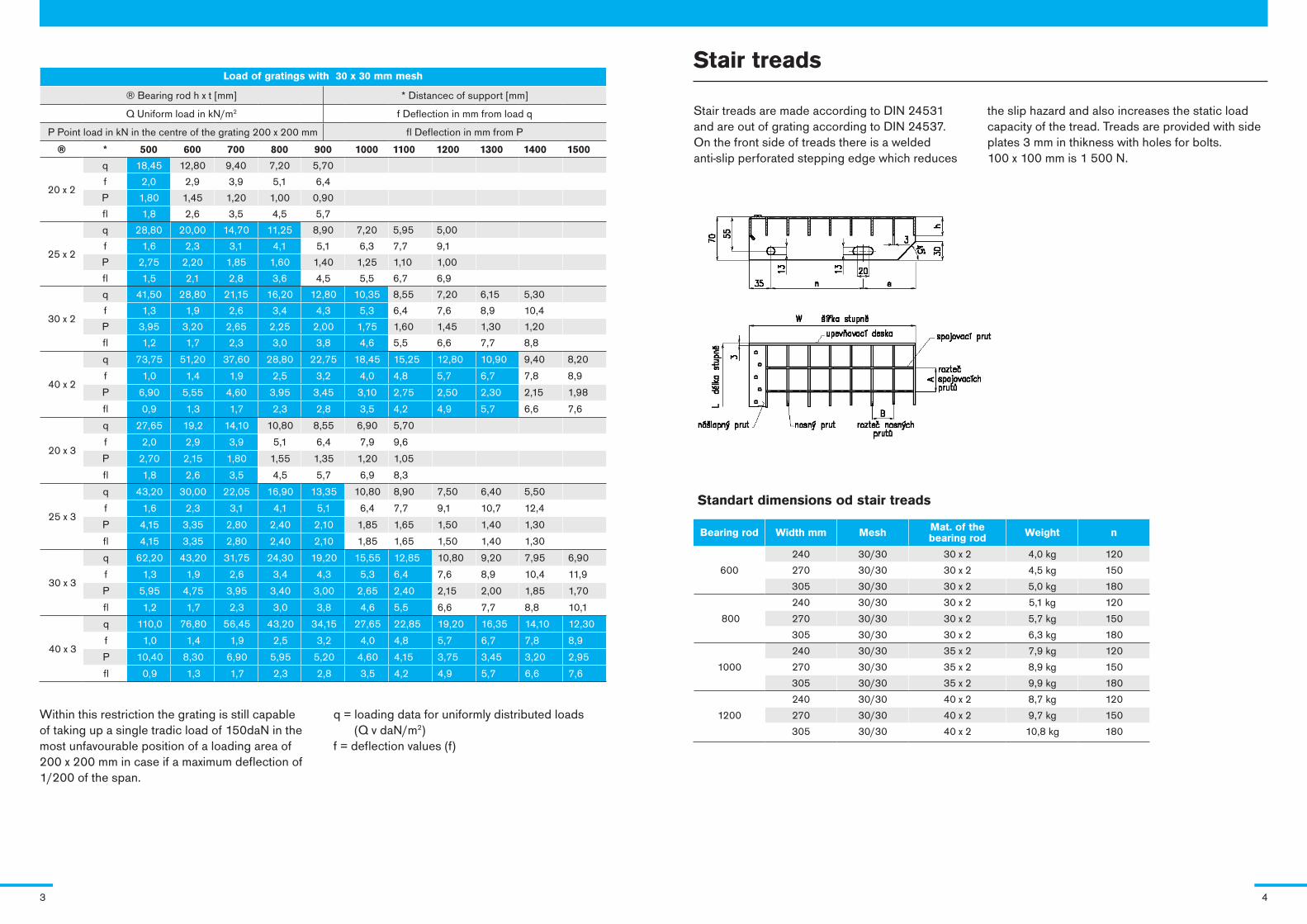
Stair treads
Stair treads are made according to DIN 24531 and are out of grating according to DIN 24537. On the front side of treads there is a welded anti-slip perforated stepping edge which reduces
the slip hazard and also increases the static load capacity of the tread. Treads are provided with side plates 3 mm in thikness with holes for bolts. 100 x 100 mm is 1 500 N.
Standart dimensions od stair treads
Bearing rod Width mm Mesh Mat. of the bearing rod Weight n
600
240 30/30 30 x 2 4,0 kg 120
270 30/30 30 x 2 4,5 kg 150
305 30/30 30 x 2 5,0 kg 180
800
240 30/30 30 x 2 5,1 kg 120
270 30/30 30 x 2 5,7 kg 150
305 30/30 30 x 2 6,3 kg 180
1000
240 30/30 35 x 2 7,9 kg 120
270 30/30 35 x 2 8,9 kg 150
305 30/30 35 x 2 9,9 kg 180
240 30/30 40 x 2 8,7 kg 120
1200 270 30/30 40 x 2 9,7 kg 150
305 30/30 40 x 2 10,8 kg 180
3 4
Stainless steel gratings, 17241 (1.4301) gradeAnti-slip type – the pressure welding grating
The detail of Anti slip classification
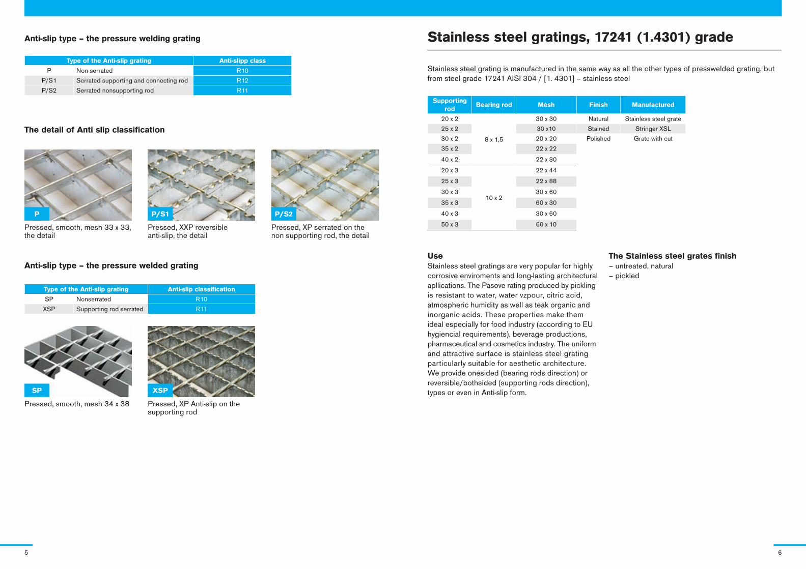
P/S1 P/S2P
xSPSP
Pressed, smooth, mesh 33 x 33, the detail
Pressed, XXP reversibleanti-slip, the detail
Pressed, XP serrated on the non supporting rod, the detail
Pressed, smooth, mesh 34 x 38 Pressed, XP Anti-slip on the supporting rod
Anti-slip type – the pressure welded grating
Type of the Anti-slip grating Anti-slip classification
SP Nonserrated R10
XSP Supporting rod serrated R11
Type of the Anti-slip grating Anti-slipp class
P Non serrated R10
P/S1 Serrated supporting and connecting rod R12
P/S2 Serrated nonsupporting rod R11
Stainless steel grating is manufactured in the same way as all the other types of presswelded grating, but from steel grade 17241 AISI 304 / [1. 4301] – stainless steel
UseStainless steel gratings are very popular for highly corrosive enviroments and long-lasting architectural apllications. The Pasove rating produced by pickling is resistant to water, water vzpour, citric acid, atmospheric humidity as well as teak organic and inorganic acids. These properties make them ideal especially for food industry (according to EU hygiencial requirements), beverage productions, pharmaceutical and cosmetics industry. The uniform and attractive surface is stainless steel grating particularly suitable for aesthetic architecture.We provide onesided (bearing rods direction) or reversible/bothsided (supporting rods direction), types or even in Anti-slip form.
The Stainless steel grates finish– untreated, natural– pickled
Supporting rod
Bearing rod Mesh Finish Manufactured
20 x 2
8 x 1,5
30 x 30 Natural Stainless steel grate
25 x 2 30 x10 Stained Stringer XSL
30 x 2 20 x 20 Polished Grate with cut
35 x 2 22 x 22
40 x 2 22 x 30
20 x 3
10 x 2
22 x 44
25 x 3 22 x 88
30 x 3 30 x 60
35 x 3 60 x 30
40 x 3 30 x 60
50 x 3 60 x 10
5 6
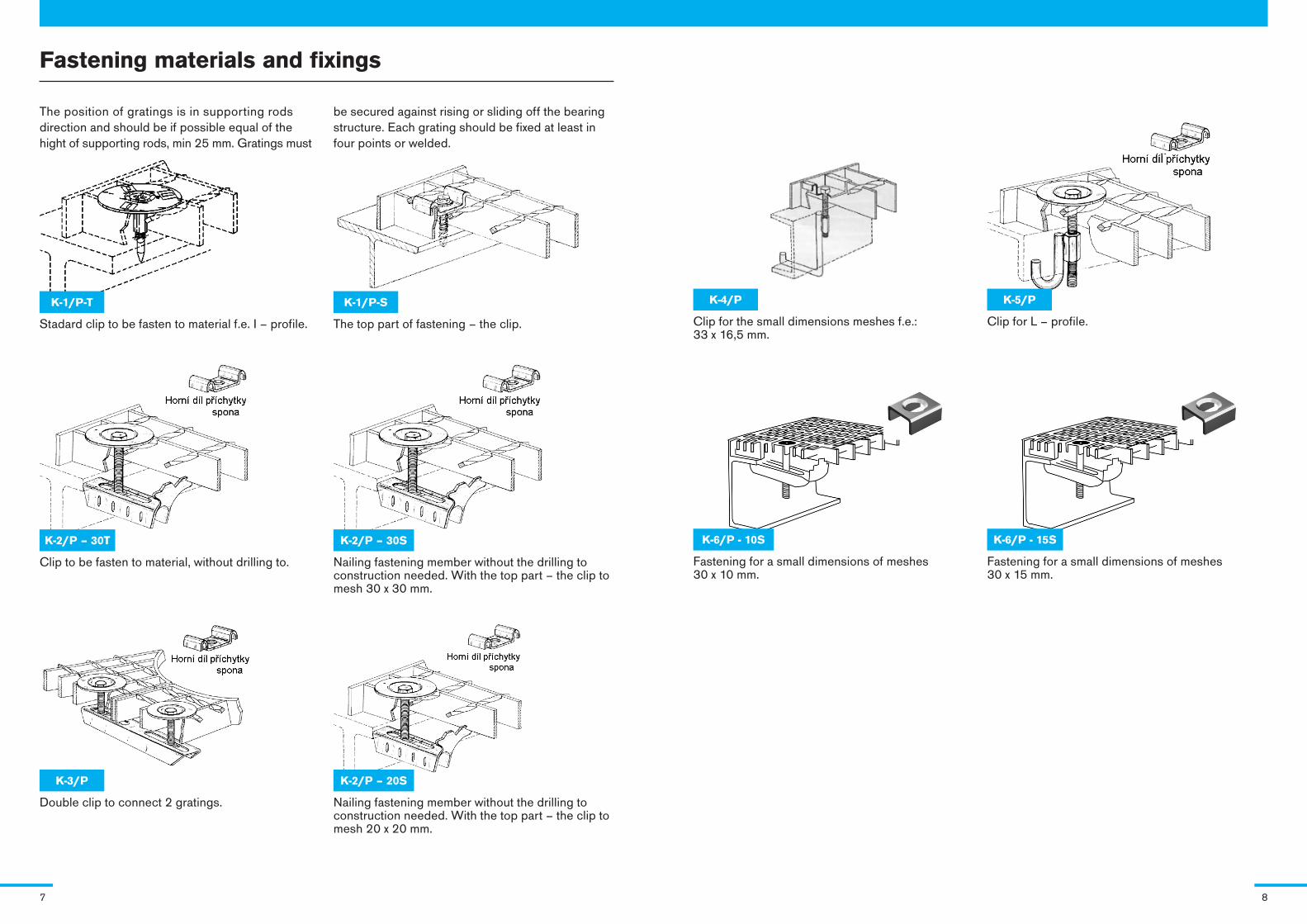
Fastening materials and fixings
The position of gratings is in supporting rods direction and should be if possible equal of the hight of supporting rods, min 25 mm. Gratings must
be secured against rising or sliding off the bearing structure. Each grating should be fixed at least in four points or welded.
K-1/P-T
Stadard clip to be fasten to material f.e. I – profile.
K-1/P-S
The top part of fastening – the clip.
K-2/P – 30T
Clip to be fasten to material, without drilling to.
K-2/P – 30S
Nailing fastening member without the drilling to construction needed. With the top part – the clip to mesh 30 x 30 mm.
K-3/P
Double clip to connect 2 gratings.
K-2/P – 20S
Nailing fastening member without the drilling to construction needed. With the top part – the clip to mesh 20 x 20 mm.
K-6/P - 10S
Fastening for a small dimensions of meshes 30 x 10 mm.
K-6/P - 15S
Fastening for a small dimensions of meshes 30 x 15 mm.
K-4/P
Clip for the small dimensions meshes f.e.: 33 x 16,5 mm.
K-5/P
Clip for L – profile.
7 8
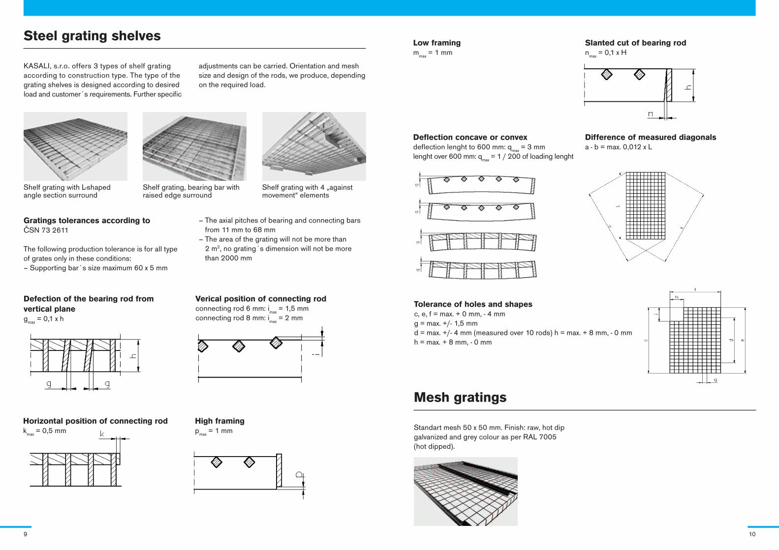
Steel grating shelves
Shelf grating with L-shaped angle section surround
Shelf grating, bearing bar with raised edge surround
Shelf grating with 4 „against movement“ elements
KASALI, s.r.o. offers 3 types of shelf grating according to construction type. The type of the grating shelves is designed according to desired load and customer´s requirements. Further specific
adjustments can be carried. Orientation and mesh size and design of the rods, we produce, depending on the required load.
Gratings tolerances according to ČSN 73 2611
The following production tolerance is for all type of grates only in these conditions: – Supporting bar´s size maximum 60 x 5 mm
– The axial pitches of bearing and connecting bars from 11 mm to 68 mm
– The area of the grating will not be more than 2 m2, no grating´s dimension will not be more than 2000 mm
Defection of the bearing rod from vertical plane g
max = 0,1 x h
Verical position of connecting rod connecting rod 6 mm: i
max = 1,5 mm
connecting rod 8 mm: imax
= 2 mm
Horizontal position of connecting rod k
max = 0,5 mm
High framing p
max = 1 mm
Low framing m
max = 1 mm
Slanted cut of bearing rod n
max = 0,1 x H
Mesh gratings
Standart mesh 50 x 50 mm. Finish: raw, hot dip galvanized and grey colour as per RAL 7005 (hot dipped).
Deflection concave or convex deflection lenght to 600 mm: q
max = 3 mm
lenght over 600 mm: qmax
= 1 / 200 of loading lenght
Difference of measured diagonals a - b = max. 0,012 x L
Tolerance of holes and shapes c, e, f = max. + 0 mm, - 4 mm g = max. +/- 1,5 mm d = max. +/- 4 mm (measured over 10 rods) h = max. + 8 mm, - 0 mmh = max. + 8 mm, - 0 mm
9 10

KASALI, s.r.o. | U Suchopádu 316/6 | CZ 669 04 Znojmo - Přímětice | IČ 25312740 | DIČ CZ25312740 tel./fax +420 515 221 301 | tel./fax +420 515 260 499 | [email protected] | www.kasali.cz
Recommended