FITTING INSTRUCTIONSTO BE FITTED BY A QUALIFIED TECHNICIAN
Secondary Alternator Cover Part No. EC-GSXR1000-L7-1-GBR / Secondary Clutch Cover Part No. EC-GSXR1000-L7-2-GBR /
Secondary Pulse / Timing Cover Part No. EC-GSXR1000-L7-3-GBR / Secondary Water Pump Cover Part No. EC-GSXR1000-L7-5-GBR /
Lower Chain Guard Part No. CGA10-GBR / Paddock Stand/Bobbin Set Part No. BA12-8-GBR-SET / Bullet Frame Sliders Set Part No. FS-GSXR1000-L7-S
THIS SHEET INCLUDES FITTING INSTRUCTIONS FOR THE FOLLOWING PARTS:
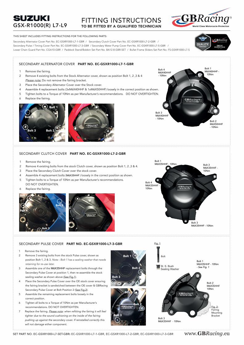
1 Remove the fairing. 2 Remove 4 existing bolts from the Stock Alternator cover, shown as position Bolt 1, 2 ,3 & 4 Please note: Do not remove the fairing bracket.3 Place the Secondary Alternator Cover over the Stock cover.4 Assemble 4 replacement bolts (3xM6X40HHF & 1xM6X50HHF) loosely in the correct position as shown.5 Tighten bolts to a Torque of 10Nm as per Manufacturer’s recommendations. DO NOT OVERTIGHTEN.6 Replace the fairing.
SECONDARY ALTERNATOR COVER PART NO. EC-GSXR1000-L7-1-GBRBolt 1M6X40HHF - 10Nm
Bolt 2M6X50HHF - 10Nm
Bolt 3M6X40HHF - 10Nm
Bolt 4M6X40HHF - 10Nm
1 Remove the fairing.2 Remove 4 existing bolts from the stock Clutch cover, shown as position Bolt 1, 2 ,3 & 4.3 Place the Secondary Clutch Cover over the stock cover.4 Assemble 4 replacement bolts (M6X35HHF ) loosely in the correct position as shown.5 Tighten bolts to a Torque of 10Nm as per Manufacturer’s recommendations.
DO NOT OVERTIGHTEN.6 Replace the fairing.
SECONDARY CLUTCH COVER PART NO. EC-GSXR1000-L7-2-GBR
Bolt 1M6X35HHF - 10Nm Bolt 2
M6X35HHF - 10Nm
Bolt 3M6X35HHF - 10Nm
Bolt 4M6X35HHF - 10Nm
GSX-R1000(R) L7-L9
Bolt 4
Bolt 1
Bolt 2Bolt 3
Bolt 4
Bolt 1
Bolt 2
Bolt 3
1 Remove the fairing.2 Remove 3 existing bolts from the stock Pulse cover, shown as
position Bolt 1, 2 & 3. Note : Bolt 1 has a sealing washer that needs
retaining for re-use later.
3 Assemble one of the M6X35HHF replacement bolts through the Secondary Pulse Cover at position 1, then re-assemble the stock sealing washer as shown above (See Fig.1).
4 Place the Secondary Pulse Cover over the OE stock cover ensuring the fairing bracket is sandwiched between the OE cover & GBRacing Secondary Pulse Cover at Bolt Position 2 (See Fig.2).
5 Assemble the remaining replacement bolts loosely in the correct position.
6 Tighten all bolts to a Torque of 10Nm as per Manufacturer’s recommendations. DO NOT OVERTIGHTEN.
7 Replace the fairing. Please note: when refitting the fairing it will feel
tighter due to the sound cushioning on the inside of the fairing
pushing up against the secondary cover. If reinstalled correctly this
will not damage either component.
SECONDARY PULSE COVER PART NO. EC-GSXR1000-L7-3-GBR
Bolt 1M6X35HHF - 10Nm - See Fig. 1
Bolt 2M6X35HHF 10Nm
Fig. 1
Bolt
St. S. BushSealing Washer
Bolt 3M6X35HHF - 10Nm
Bolt 3
Bolt 1
Bolt 2
Fig. 2:Fairing Mounting Bracket
www.GBRacing.euSET PART NO. EC-GSXR1000-L7-SET-GBR: EC-GSXR1000-L7-1-GBR, EC-GSXR1000-L7-2-GBR, EC-GSXR1000-L7-3-GBR
Bolt 3
Bolt 1
Bolt 2

CPM-3
CPB-10-30
M10x1.25x50
FITTING INSTRUCTIONSTO BE FITTED BY A QUALIFIED TECHNICIAN
1 Assemble M8 x 40mm Bolt through the moulded bobbin.
2 Tighten bolts to swing arm boss, 8 Nm.
DO NOT OVERTIGHTEN
PADDOCK STAND / BOBBIN SET PART NO. BA12-8-GBR-SET
(1) Assemble M8 x 40mm Bolt thru moulded bobbin.
(2) Tighten bolts to swing arm boss , 8 N/m.
Do not overtighten.
Fitting Instructions
To be fitted by a qualified Technician
1 off M8 x 40 Bolts
1 off Moulded Paddock stand/bobbin
BA12-8-GBR
(1) Assemble M8 x 40mm Bolt thru moulded bobbin.
(2) Tighten bolts to swing arm boss , 8 N/m.
Do not overtighten.
Fitting Instructions
To be fitted by a qualified Technician
1 off M8 x 40 Bolts
1 off Moulded Paddock stand/bobbin
BA12-8-GBR
(1) Assemble M8 x 40mm Bolt thru moulded bobbin.
(2) Tighten bolts to swing arm boss , 8 N/m.
Do not overtighten.
Fitting Instructions
To be fitted by a qualified Technician
1 off M8 x 40 Bolts
1 off Moulded Paddock stand/bobbin
BA12-8-GBR
(1) Assemble M8 x 40mm Bolt thru moulded bobbin.
(2) Tighten bolts to swing arm boss , 8 N/m.
Do not overtighten.
Fitting Instructions
To be fitted by a qualified Technician
1 off M8 x 40 Bolts
1 off Moulded Paddock stand/bobbin
BA12-8-GBR
1 x Moulded Paddock Stand / Bobbin
1 x M8 x 40 Bolt
DO NOT use these products unless you agree to our Terms & Conditions, as shown on our paperwork and website. If you do not agree, please return the product(s) to your dealer for a refund.
GSX-R1000(R) L7-L9
1 Assemble 2 bolts and washers through the lower chain guard into the Black Anodised aluminium mounting block CGA10-2.2 Position the assembly underneath the swing arm, closing the gap to the rear sprocket. Note : There should be a 5mm minimum gap from the bike chain to the lower chain guard.3 Mark off the chosen hole positions.4 Drill & Tap the marked holes , M6 - (Drill 5mm Dia. for tapping)5 Disassemble the Black Anodised block from the assembly, and mount the block to the underside of the swing arm
using the remaining 2 bolts and washers. 6 Re-assemblethelowerchainguardtothefixedbracket.
LOWER CHAIN GUARD PART NO. CGA10-GBR 2 x Bolts & WashersM6x20 - 10Nm
1 Remove the fairing.2 Unscrewtheenginemountingsufficientlysothatthe
bolt will mark the inside of the fairing.3 Mark the head of the unscrewed bolt with a marker
pen and assemble the fairing back, pushing in the area of the unscrewed bolt head.
4 Remove the fairing and drill a 22mm Diameter through hole where the head of the engine mount bolt has marked.
5 Now remove the engine bolt fully.6 Replace the fairing. 7 Assemble replacement engine mount bolt through the
aluminium bush into correct position.8 Tighten to 75NM torque.9 Slide bullet moulding onto aluminium bush.10 Screw M6 bolt into front of bullet moulding hand tight.
BULLET FRAME SLIDER - LEFT & RIGHT HAND SIDE - RACE - PART NOS. FS-GSXR1000-L7-RHS-R & FS-GSXR1000-L7-LHS-R
CPM-3
CPB-10-25
M10x1.25x50
CPM-3
CPB-10-45
M10x1.25x50
CPM-3
CPB-10-50
M10x1.25x50
RIGHT HAND SIDELEFT HAND SIDE
1 Remove the fairing.2 Unscrewtheenginemountingsufficientlysothatthe
bolt will mark the inside of the fairing.3 Mark the head of the unscrewed bolt with a marker
pen and assemble the fairing back, pushing in the area of the unscrewed bolt head.
4 Remove the fairing and drill a 22mm Diameter through hole where the head of the engine mount bolt has marked.
5 Now remove the engine bolt fully.6 Replace the fairing. 7 Assemble replacement engine mount bolt through the
aluminium bush into correct position.8 Tighten to 75NM torque.9 Slide bullet moulding onto aluminium bush.10 Screw M6 bolt into front of bullet moulding hand tight.
BULLET FRAME SLIDER - LEFT & RIGHT HAND SIDE - STREET - PART NO. FS-GSXR1000-L7-RHS-S & FS-GSXR1000-L7-LHS-S
RIGHT HAND SIDELEFT HAND SIDE
1 Fitting requires a COLD engine.
2 See Fig 1: Gently loosen Jubilee clip 1 and rotate clip to
the left (as shown). Gently loosen Jubilee clip 2 & push clip
back towards the engine to create space to fit secondary cover.
Move cable 3 to tuck in behind OE cover as shown.
3 Place secondary water pump cover over stock cover by sliding
in from the right hand side.
4 Assemble replacement Bolt 1 into position first - do not tighten.
Then assemble Bolt 2 into position - do not tighten.
5 Do not attempt to tighten bolts until both are in position and
secondary water pump cover feels seated in position.
8 Tighten bolts to a Torque of 10Nm. DO NOT OVERTIGHTEN.
Bolt 2M6X40HHF
- 10Nm
Bolt 1M6X40HHF - 10Nm
SECONDARY WATER PUMP COVER PART NO. EC-GSXR1000-L7-5-GBR JUBILEE
CLIP 1
Fig 1
JUBILEECLIP 2
Rotateclip to left
Push CLIP backwards
CABLE 3 -tuck in behind OE cover
Bolt 1Bolt 2