© This document has been developed and released by UNISIG
SUBSET-039
Version 3.1.0
FIS for the RBC/RBC Handover Page 1/72
ERTMS/ETCS
FIS for the RBC/RBC Handover
REF : SUBSET-039
ISSUE : 3.1.0
DATE : 09-05-2014
Company Technical Approval Management approval
ALSTOM
ANSALDO
AZD
BOMBARDIER
CAF
SIEMENS
THALES
© This document has been developed and released by UNISIG
SUBSET-039
Version 3.1.0
FIS for the RBC/RBC Handover Page 2/72
1. MODIFICATION HISTORY
Issue Number
Date
Section Number Modification / Description Author
0.0.1
990902
All Document creation OG
1.0.0
991014
Version number Release version HE
1.0.1
000203
See revision marks Updated to be compliant
with SRS class 1 v2.0.0
OG
1.0.2
000314
See revision marks Train characteristics for
route suitability removed
from “Preannouncement”
message
OG
2.0.0
000330
Final issue to ECSAG U.D. (ed)..
Version 2.1.0
(16-June-2005)
all Draft enhancements by WP
RBC HOV FIS
LK
Version 2.1.1
(11-AUG-2005)
3.2.1.1,
6.3.1.1
Subset-108 added, Packet
88 deleted
LK
Version 2.1.2
(31-AUG-2005)
Modifications acc. To email
comments
LK
Version 2.2.9
(11-Feb-2009)
all Consistency with SRS 2.3.0
and Subset-108 v1.2.0
WP RBC/RBC
Handover
Version 2.2.10
(17-March-2009)
B.1.1.1
6.2.1.1
5.1.1.1, 5.1.1.2,
5.1.1.3
Table 9, 5.3.1.3
6.3.1.2
6.3.4.1
6.2.4.2, 6.6.1.22
6.6.1.3
3.2.1.1
Amendments based on
comments from EEIG Users
Group during a joint meet-
ing on 11-March-2009
WP RBC/RBC
Handover
Version 2.2.11
(27-March-2009)
3.2
Table 9
6.6.1.5
Amendments based on
comments received from
ERA, e-mail 18-March-
2009.
WP RBC/RBC
Handover
© This document has been developed and released by UNISIG
SUBSET-039
Version 3.1.0
FIS for the RBC/RBC Handover Page 3/72
Issue Number
Date
Section Number Modification / Description Author
B.1.1.1 Editorial update in Table 9.
Version 2.3.0
(7-April-2009)
Version 2.3.0 created for
official release after Unisig
SC approval. No change in
the contents.
WP RBC/RBC
Handover
Version 3.0.0
(2-Dec-2010)
Consistency of Subset-039
with SRS 3.1.0.
WP RBC/RBC
Handover
Version 3.0.1
(29-Apr-2011)
Consistency of Subset-039
with SRS 3.2.0.
WP RBC/RBC
Handover
Version 3.0.2
(09-Dec-2011)
Update based on review
comments, elaborating
Backwards Compatibility
WP RBC/RBC
Handover
Version 3.0.3
(10-Feb-2012)
Update based on review of
version 3.0.2 WP RBC/RBC
Handover
Version 3.0.4
(10-Aug-2012)
Update based on review of
version 3.0.3 and Workshop
WP+SG+ERA
WP RBC/RBC
Handover
Version 3.0.5
(30-Oct-2012)
Updated based on CR1088
as well as CR413, CR459,
CR535, CR637, CR656,
CR676, CR731, CR745,
CR757, CR809, CR1133,
CR1135 and CR1140.
Updated based on review of
version 3.0.4.
WP RBC/RBC
Handover
Version 3.0.6 UNISIG internal version WP RBC/RBC
Handover
Version 3.0.7
UNISIG internal version WP RBC/RBC
Handover
Version 3.0.8 (16-Oct-
2013)
Updated based on:
- CR1088 including ERA
comments of entry 24/09/13
and Super Group com-
ments of entry 24/09/13.
- CR1143, CR1159 and
CR1168.
UNISIG
© This document has been developed and released by UNISIG
SUBSET-039
Version 3.1.0
FIS for the RBC/RBC Handover Page 4/72
Issue Number
Date
Section Number Modification / Description Author
Version 3.0.9 Update based on principles
retained in CG meeting
06/02/14
ERA
Version 3.0.10
(15-Apr-2014)
Updated to incorporate all
review comments and edito-
rial corrections
UNISIG
Version 3.0.11
(24-Apr-2014)
3.3 Update to incorporate ERA
comment about removing
TSR and LX
Baseline 3 1st Maintenance
pre-release version
UNISIG
3.1.0
09/05/14
- Baseline 3 1st Maintenance
release version PP
© This document has been developed and released by UNISIG
SUBSET-039
Version 3.1.0
FIS for the RBC/RBC Handover Page 5/72
2. TABLE OF CONTENTS
1. MODIFICATION HISTORY ............................................................................................................... 2
2. TABLE OF CONTENTS .................................................................................................................... 5
3. INTRODUCTION ............................................................................................................................. 7
3.1 Scope and Purpose ........................................................................................................... 7
3.2 References ....................................................................................................................... 7
3.3 Terms and Abbreviations .................................................................................................. 7
4. RBC/RBC HANDOVER .................................................................................................................. 9
4.1 Overview ........................................................................................................................... 9
4.2 RBC/RBC Communication ................................................................................................ 9
4.3 RBC/RBC Handover Transaction .................................................................................... 10
4.4 RBC/RBC Communication Supervision ........................................................................... 11
4.5 RBC/RBC Handover Task Description ............................................................................ 11
4.5.1 Handing Over RBC .................................................................................................. 11
4.5.2 Accepting RBC ......................................................................................................... 12
4.6 State Tables .................................................................................................................... 13
4.6.1 General .................................................................................................................... 13
4.6.2 State Table of Handing Over RBC ........................................................................... 14
4.6.3 State Table of Accepting RBC .................................................................................. 17
4.6.4 State Table for Communication Supervision ............................................................ 21
4.7 Configuration Management ............................................................................................. 23
5. MESSAGES ................................................................................................................................ 24
5.1 General ........................................................................................................................... 24
5.2 Messages from the Handing Over RBC to the Accepting RBC ........................................ 26
5.2.1 Pre-Announcement .................................................................................................. 26
5.2.2 Route Related Information Request ......................................................................... 26
5.2.3 Announcement ......................................................................................................... 28
5.2.4 RRI Confirmation ..................................................................................................... 28
5.2.5 Train Data ................................................................................................................ 29
5.2.6 Train Running Number ............................................................................................. 29
5.3 Messages from the Accepting RBC to the Handing Over RBC ........................................ 30
5.3.1 Route Related Information ....................................................................................... 30
5.3.2 Taking Over Responsibility ....................................................................................... 31
5.3.3 Request for RRI Confirmation .................................................................................. 32
5.4 Messages from both Accepting RBC or Handing Over RBC ........................................... 32
© This document has been developed and released by UNISIG
SUBSET-039
Version 3.1.0
FIS for the RBC/RBC Handover Page 6/72
5.4.1 Acknowledgement .................................................................................................... 32
5.4.2 Cancellation ............................................................................................................. 33
5.4.3 Life Sign ................................................................................................................... 33
5.5 Packets ........................................................................................................................... 33
5.6 Variables ......................................................................................................................... 34
6. MANAGEMENT OF OLDER SYSTEM VERSIONS ............................................................................... 41
6.1 Scope.............................................................................................................................. 41
6.2 General Requirements .................................................................................................... 42
6.3 Exceptions to Chapter 4 .................................................................................................. 42
6.4 Exceptions to Chapter 5 .................................................................................................. 43
6.5 Additional Requirements for an RBC X=2 Communicating with an RBC X=1 .................. 47
6.5.1 General .................................................................................................................... 47
6.5.2 T1: Information Received by RBCACC X=2 from RBCHOV X=1 ................................... 48
6.5.3 T2: Information Sent by RBCACC X=2 to RBCHOV X=1 ............................................... 49
6.5.4 T3: Information Sent by RBCHOV X=2 to RBCACC X=1 ............................................... 52
6.5.5 T4: Information Received by RBCHOV X=2 from RBCACC X=1 ................................... 54
6.6 Additional Requirements when System Version 1.1 is Applicable for the Interface .......... 57
ANNEX A – (INFORMATIVE) RBC/RBC COMMUNICATION ................................................................ 59
A.1 The RBC/RBC Communication Model............................................................................. 59
A.2 Initialisation of RBC/RBC Communication ....................................................................... 59
A.3 Data Transfer .................................................................................................................. 60
A.4 Example of Message Sequence ...................................................................................... 61
A.5 Example of Life Sign ....................................................................................................... 62
A.6 Error Handling ................................................................................................................. 63
ANNEX B – INTERFACE DETAILS FOR RBC X=1 ............................................................................. 64
B.1 State Table of Handing Over RBC .................................................................................. 64
B.2 State Table of Accepting RBC ......................................................................................... 67
B.3 Example of X=1 Life Sign ................................................................................................ 71
© This document has been developed and released by UNISIG
SUBSET-039
Version 3.1.0
FIS for the RBC/RBC Handover Page 7/72
3. INTRODUCTION
3.1 Scope and Purpose
3.1.1.1 This document specifies the functional interface for the RBC/RBC communication to
perform an RBC/RBC handover according to the principles and procedures in the SRS
[Subset-026].
3.1.1.2 The purpose of this specification is to enable any pair of neighbouring RBCs compliant
with it to be interconnected so that RBC/RBC handovers can be performed, inde-
pendently of the functional characteristics, service performance and safety of the con-
cerned RBCs, which are outside the scope of this specification.
3.2 References
3.2.1.1 The following documents are referenced in this document
Reference Title
Subset-023 Glossary of Terms and Abbreviations
Subset-026 System Requirements Specification
Subset-035 Specific Transmission Module FFFIS
Subset-040 Dimensioning and Engineering rules
Subset-098 RBC-RBC Safe Communication Interface
3.3 Terms and Abbreviations
3.3.1.1 For general terms and abbreviations refer to [Subset-023]. Additional terms and
abbreviations relevant for RBC/RBC handover and used in this document are specified
here.
Term Definition
EoA interval Part of track from one EoA/LoA location to the next EoA/LoA lo-
cation, as defined by the trackside design
NRBC message Message sent to or received from a neighbour RBC
RBC/RBC commu-
nication entity
An application entity responsible for RBC/RBC handover protocol
handling, for one or more handovers depending on
implementation
© This document has been developed and released by UNISIG
SUBSET-039
Version 3.1.0
FIS for the RBC/RBC Handover Page 8/72
Term Definition
RBC/RBC handover
protocol
The protocol for information exchange between RBCs, to support
the RBC/RBC handover.
RBC/RBC handover
transaction
The sequence of (NRBC) messages between RBCs to support
the passing of an engine from one RBC to an adjacent RBC
(neighbour RBC).
Abbreviation Definition
ACC Accepting
BG Balise group
ETCS ID ETCS Identity
HOV Handover
N/A Not applicable
NRBC Neighbour RBC
RBCACC Accepting RBC
RBCHOV Handing Over RBC
RRI Route Related Information
SAP Service access point
TOR Taking Over Responsibility
© This document has been developed and released by UNISIG
SUBSET-039
Version 3.1.0
FIS for the RBC/RBC Handover Page 9/72
4. RBC/RBC HANDOVER
4.1 Overview
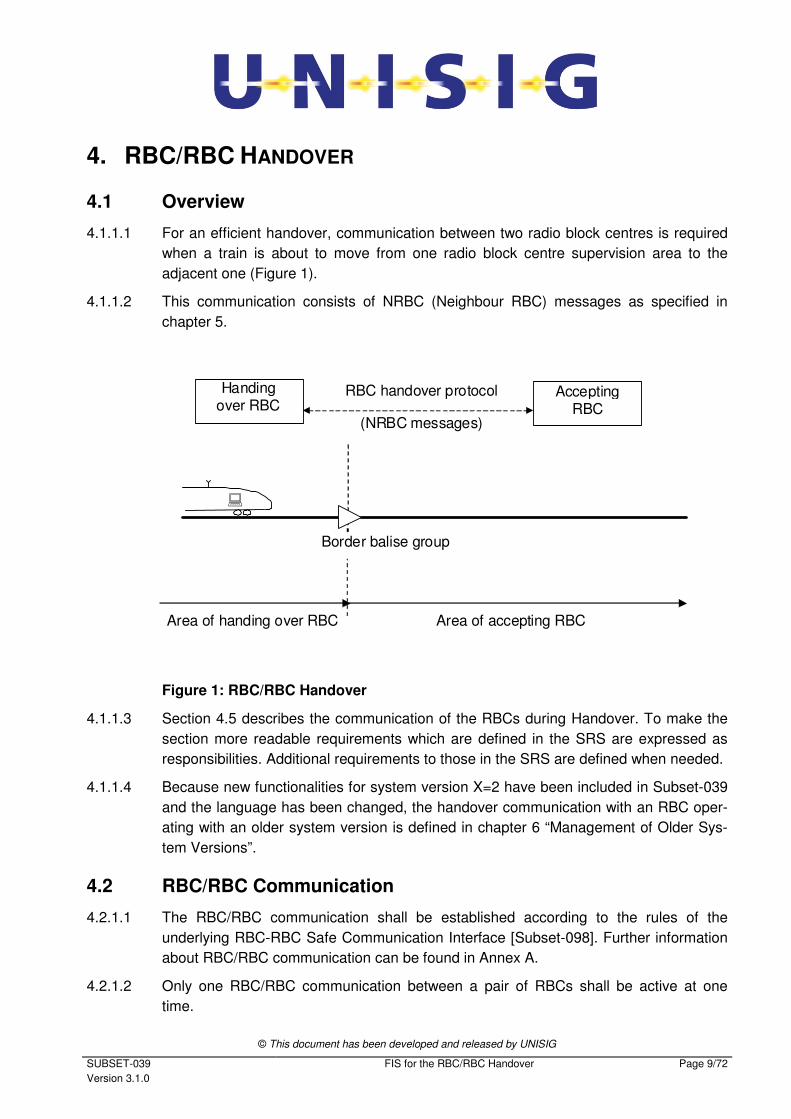
4.1.1.1 For an efficient handover, communication between two radio block centres is required
when a train is about to move from one radio block centre supervision area to the
adjacent one (Figure 1).
4.1.1.2 This communication consists of NRBC (Neighbour RBC) messages as specified in
chapter 5.
RBC handover protocol Handing
over RBC
Border balise group
�
Area of handing over RBC Area of accepting RBC
Accepting RBC
(NRBC messages)
Figure 1: RBC/RBC Handover
4.1.1.3 Section 4.5 describes the communication of the RBCs during Handover. To make the
section more readable requirements which are defined in the SRS are expressed as
responsibilities. Additional requirements to those in the SRS are defined when needed.
4.1.1.4 Because new functionalities for system version X=2 have been included in Subset-039
and the language has been changed, the handover communication with an RBC oper-
ating with an older system version is defined in chapter 6 “Management of Older Sys-
tem Versions”.
4.2 RBC/RBC Communication
4.2.1.1 The RBC/RBC communication shall be established according to the rules of the
underlying RBC-RBC Safe Communication Interface [Subset-098]. Further information
about RBC/RBC communication can be found in Annex A.
4.2.1.2 Only one RBC/RBC communication between a pair of RBCs shall be active at one
time.
© This document has been developed and released by UNISIG
SUBSET-039
Version 3.1.0
FIS for the RBC/RBC Handover Page 10/72
4.2.1.3 Note: One RBC/RBC communication is able to handle all necessary handover
transactions between a pair of RBCs.
4.2.1.4 The RBC/RBC communication shall provide for the exchange of NRBC messages (as
specified in chapter 5) in both directions simultaneously, i.e. the RBC/RBC HOV
transaction(s).
4.2.1.5 The RBC/RBC communication entities of Handing Over RBC and Accepting RBC are
identified by their ETCS ID.
4.3 RBC/RBC Handover Transaction
4.3.1.1 The RBC/RBC HOV transaction is identified by the ETCS ID of the engine and the
ETCS ID of the border balise group.
4.3.1.1.1 Note: In case of more than one communicating engine in a train each engine has its
own RBC/RBC handover transaction.
4.3.1.2 It shall be possible for an RBC to act as the Accepting and as the Handing Over RBC
for different engines at different RBC border locations simultaneously.
4.3.1.3 The RBC shall be able to handle RBC/RBC handover transactions which,
a) follow each other (i.e. the first RBC/RBC HOV transaction is finished before the sec-
ond starts),
b) overlap (i.e. RBC/RBC HOV transactions are handled simultaneously),
c) overlap with inverted roles of RBCs,
d) are cancelled without an engine being handed over.
4.3.1.4 When the Accepting RBC receives a pre-announcement message for a transaction
after the first RRI Request message, it shall consider this as a cancellation condition for
the already on-going transaction.
4.3.1.4.1 Note: the new pre-announcement may indicate that a cancellation was missed by the
Accepting RBC or that a loss of communication was not recognised by the Accepting
RBC.
4.3.1.4.2 Note: A cancellation condition will cause the Accepting RBC to send a cancellation
message which cancels any transaction on-going for the specified engine in the Can-
cellation message.
4.3.1.5 When the Accepting RBC receives a pre-announcement message with the same en-
gine identity and a different border balise group as another on-going transaction it shall
consider this as a cancellation condition for the transactions with that engine identity.
4.3.1.6 When the Accepting RBC receives a pre-announcement message with the same bor-
der balise group and a different engine identity as another on-going transaction it shall
consider this as a cancellation condition for the transactions with that border balise
group if more than one of the engines (including the newly pre-announced one) has
been pre-announced with a mode other than Non Leading mode.
© This document has been developed and released by UNISIG
SUBSET-039
Version 3.1.0
FIS for the RBC/RBC Handover Page 11/72
4.3.1.7 When the Accepting RBC receives a pre-announcement message which is considered
as a cancellation condition, this pre-announcement message shall not be used to es-
tablish a new transaction.
4.3.1.8 The Accepting RBC shall not send Route Related Information before receiving the first
RRI Request message.
4.4 RBC/RBC Communication Supervision
4.4.1.1 The ability for a pair of neighbouring RBCs to communicate shall be supervised after
the establishment of a safe connection and for as long as this safe connection exists,
see also section 4.6.4.
4.4.1.2 If the safe connection between the RBCs is lost (e.g. by an error in the lower layers):
a) Re-establishment of the safe connection shall be requested by the RBC
responsible for this task (see Table 13, list item 2)
b) The RBC/RBC communication shall be regarded as lost.
4.4.1.3 If the communication between the RBCs is lost:
a) Any ongoing handover transaction shall be aborted.
b) If at this instance a safe connection between RBCs still exists it shall be terminated
and regarded as lost.
4.4.1.4 If the RBC/RBC communication is lost during an ongoing RBC/RBC handover transac-
tion, each RBC shall take any further necessary action according to its own rules.
4.4.1.5 After establishment of a safe connection the communication shall be regarded as
established and each RBC shall send a (first) Life Sign message.
4.4.1.6 Each RBC shall send an appropriate NRBC message before a specified time has
passed since any NRBC message was sent. Without an ongoing handover transaction
or when no other message has to be sent in an ongoing transaction the Life Sign mes-
sage shall be used for this purpose.
4.4.1.7 An RBC shall consider the RBC/RBC communication lost if no consistent NRBC mes-
sage has been received within a specified time (see Table 13, list item 6) since recep-
tion of the last consistent message (see section 5.1).
4.4.1.7.1 Note: The RBCs might not detect loss of RBC/RBC communication at the same time.
4.5 RBC/RBC Handover Task Description
4.5.1 Handing Over RBC
4.5.1.1 The Handing Over RBC is responsible to send information about an approaching train
to the Accepting RBC area (i.e. pre-announcement).
© This document has been developed and released by UNISIG
SUBSET-039
Version 3.1.0
FIS for the RBC/RBC Handover Page 12/72
4.5.1.2 The Handing Over RBC is responsible to request route related information when
necessary, i.e. for efficient handover when a train is moving towards a border, and is
allowed to limit the amount of route related information to be received.
4.5.1.3 The Handing Over RBC is responsible to forward route related information received
from the Accepting RBC to the relevant ETCS on-board equipment.
4.5.1.4 In case the Accepting RBC requests a confirmation for route related information con-
taining a shortened MA, the Handing Over RBC shall send a positive confirmation
when the train is able to stop before the new end of authority.
4.5.1.4.1 Note: A negative confirmation means that the train may not be able to stop before the
new end of movement authority.
4.5.1.4.2 Note: It is the responsibility of the RBCHOV how to handle the contained shortened MA
towards the on-board, for example by co-operative shortening of the MA or a shortened
MA.
4.5.1.5 The Handing Over RBC is responsible to cancel a transition to the Accepting RBC
when necessary.
4.5.1.6 The Handing Over RBC shall forward train data to the Accepting RBC during an ongo-
ing handover transaction when received from the related ETCS on-board equipment.
4.5.1.7 The Handing Over RBC shall forward the train running number to the Accepting RBC
during an ongoing handover transaction, when received from or sent to the related
ETCS on-board equipment.
4.5.1.8 The Handing Over RBC is responsible to take an appropriate action (e.g. message
repetition) if a requested acknowledgement is not received from the Accepting RBC as
expected.
4.5.2 Accepting RBC
4.5.2.1 After the acknowledgement of pre-announcement from the Handing Over RBC, the
Accepting RBC is allowed to send route related information to the Handing Over RBC.
4.5.2.2 The Accepting RBC is responsible to send route related information as often as
necessary, according to its own rules.
4.5.2.2.1 Note: The Accepting RBC assumes that any route related information sent to the Hand-
ing Over RBC will be forwarded to the relevant ETCS on-board equipment, according
to the rules of the Handing Over RBC.
4.5.2.3 The Accepting RBC is responsible to limit the route related information according to the
last received route related information request if one has been received.
4.5.2.4 The Accepting RBC shall only send route related information containing a shortened
MA with request for confirmation, after at least one route related information was sent
to the RBCHOV and this message has been acknowledged.
© This document has been developed and released by UNISIG
SUBSET-039
Version 3.1.0
FIS for the RBC/RBC Handover Page 13/72
4.5.2.5 The Accepting RBC is responsible to base any route related information it sends on the
last train data received from the on-board. In case no train data has been received from
the on-board, the Accepting RBC is responsible to base any route related information it
sends on the last train data received from the Handing Over RBC.
4.5.2.6 After acknowledging new train data received from the Handing Over RBC and if any
Route Related Information (RRI) has previously been sent, the Accepting RBC shall
immediately send RRI.
4.5.2.7 The Accepting RBC is responsible to send a Taking over responsibility message after
the condition “border passed” is detected (see Table 6).
4.5.2.8 The Accepting RBC is allowed to cancel an RBC-RBC handover transaction when
necessary.
4.5.2.9 The Accepting RBC is responsible to take an appropriate action (e.g. message repeti-
tion) if a requested acknowledgement is not received from the Handing Over RBC as
expected.
4.6 State Tables
4.6.1 General
4.6.1.1 Without restriction to the implementation of the internal RBC behaviour this section 4.6
formally describes the communication required to support an RBC/RBC handover
transaction. The RBC shall conform to the external behaviour at the RBC/RBC
interface.
4.6.1.2 The description of the data exchange at the RBC/RBC interface is given by state
transition tables, which show the states of an RBC/RBC communication entity, the
incoming events, the actions taken and the resultant states.
4.6.1.3 At each intersection of state and incoming event a state transition table specifies a
transition which may include actions, consisting of a list of outgoing events (none, one,
or more), followed by the resulting state.
4.6.1.4 If the intersection of state and incoming event is left blank then the incoming event is
invalid in the respective state. In this case an error notification may be given (imple-
mentation matter) and the state remains unchanged.
4.6.1.5 Note:
a) The actions to build a NRBC message before sending are not shown in the state
transition table.
b) The consistency checks of a received NRBC message and - in case of an error - the
resulting actions are not shown in the state transition table.
4.6.1.6 All events, which indicate the reception of a NRBC message implicitly, include checking
that the message is consistent.
© This document has been developed and released by UNISIG
SUBSET-039
Version 3.1.0
FIS for the RBC/RBC Handover Page 14/72
4.6.2 State Table of Handing Over RBC
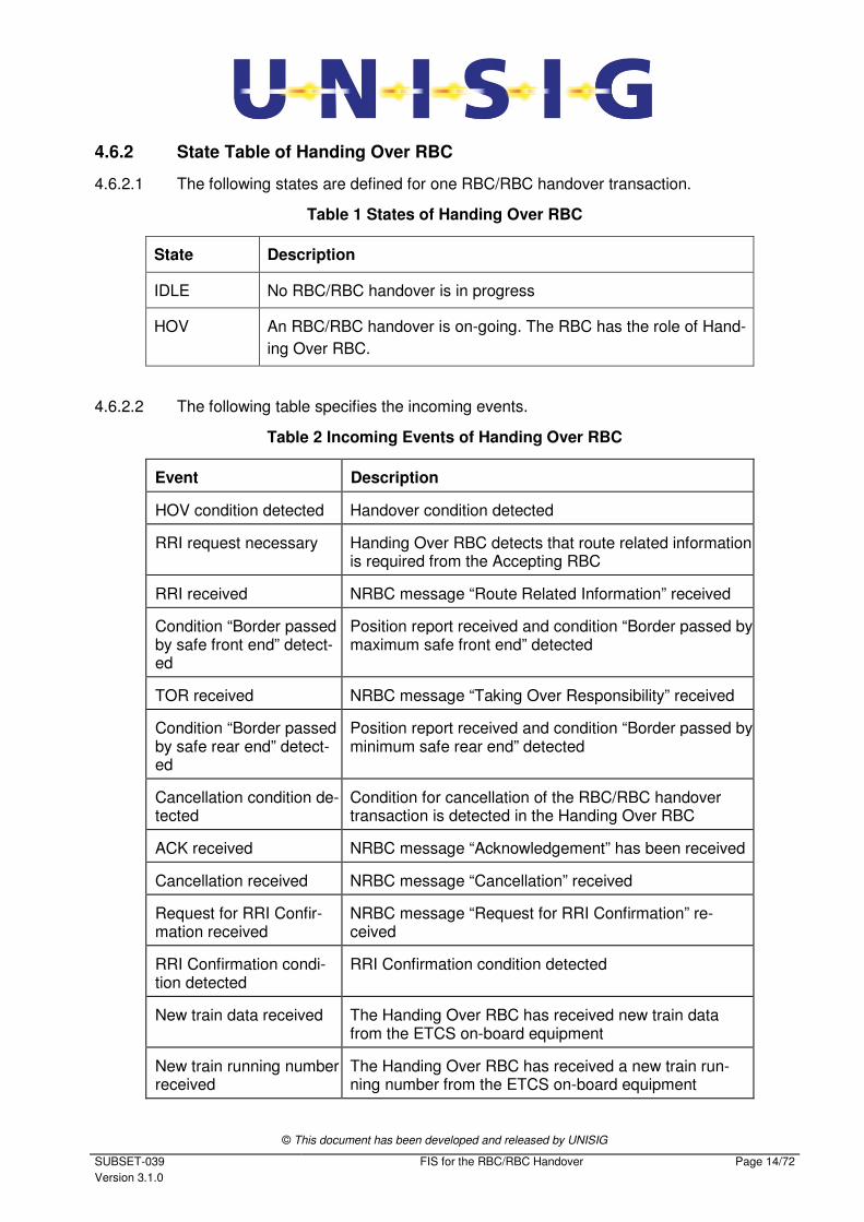
4.6.2.1 The following states are defined for one RBC/RBC handover transaction.
Table 1 States of Handing Over RBC
State Description
IDLE No RBC/RBC handover is in progress
HOV An RBC/RBC handover is on-going. The RBC has the role of Hand-
ing Over RBC.
4.6.2.2 The following table specifies the incoming events.
Table 2 Incoming Events of Handing Over RBC
Event Description
HOV condition detected Handover condition detected
RRI request necessary Handing Over RBC detects that route related information is required from the Accepting RBC
RRI received NRBC message “Route Related Information” received
Condition “Border passed by safe front end” detect-ed
Position report received and condition “Border passed by maximum safe front end” detected
TOR received NRBC message “Taking Over Responsibility” received
Condition “Border passed by safe rear end” detect-ed
Position report received and condition “Border passed by minimum safe rear end” detected
Cancellation condition de-tected
Condition for cancellation of the RBC/RBC handover transaction is detected in the Handing Over RBC
ACK received NRBC message “Acknowledgement” has been received
Cancellation received NRBC message “Cancellation” received
Request for RRI Confir-mation received
NRBC message “Request for RRI Confirmation” re-ceived
RRI Confirmation condi-tion detected
RRI Confirmation condition detected
New train data received The Handing Over RBC has received new train data from the ETCS on-board equipment
New train running number received
The Handing Over RBC has received a new train run-ning number from the ETCS on-board equipment
© This document has been developed and released by UNISIG
SUBSET-039
Version 3.1.0
FIS for the RBC/RBC Handover Page 15/72
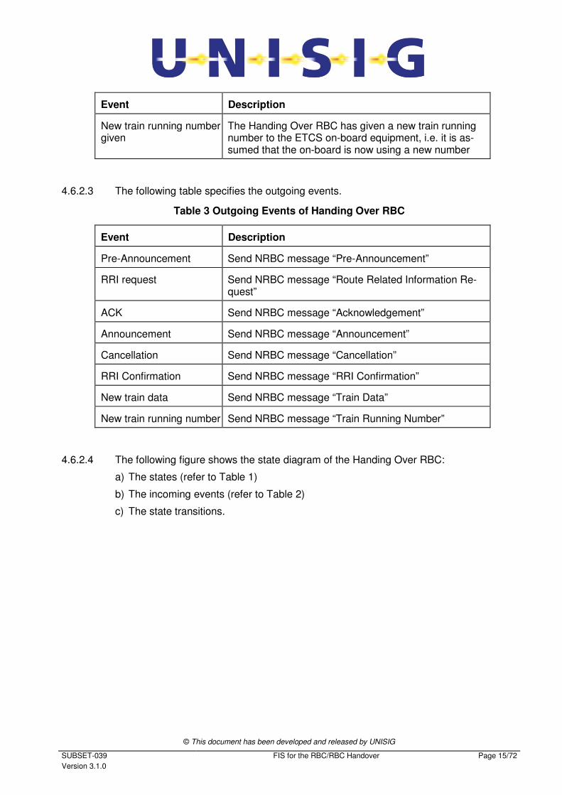
Event Description
New train running number given
The Handing Over RBC has given a new train running number to the ETCS on-board equipment, i.e. it is as-sumed that the on-board is now using a new number
4.6.2.3 The following table specifies the outgoing events.
Table 3 Outgoing Events of Handing Over RBC
Event Description
Pre-Announcement Send NRBC message “Pre-Announcement”
RRI request Send NRBC message “Route Related Information Re-quest”
ACK Send NRBC message “Acknowledgement”
Announcement Send NRBC message “Announcement”
Cancellation Send NRBC message “Cancellation”
RRI Confirmation Send NRBC message “RRI Confirmation”
New train data Send NRBC message “Train Data”
New train running number Send NRBC message “Train Running Number”
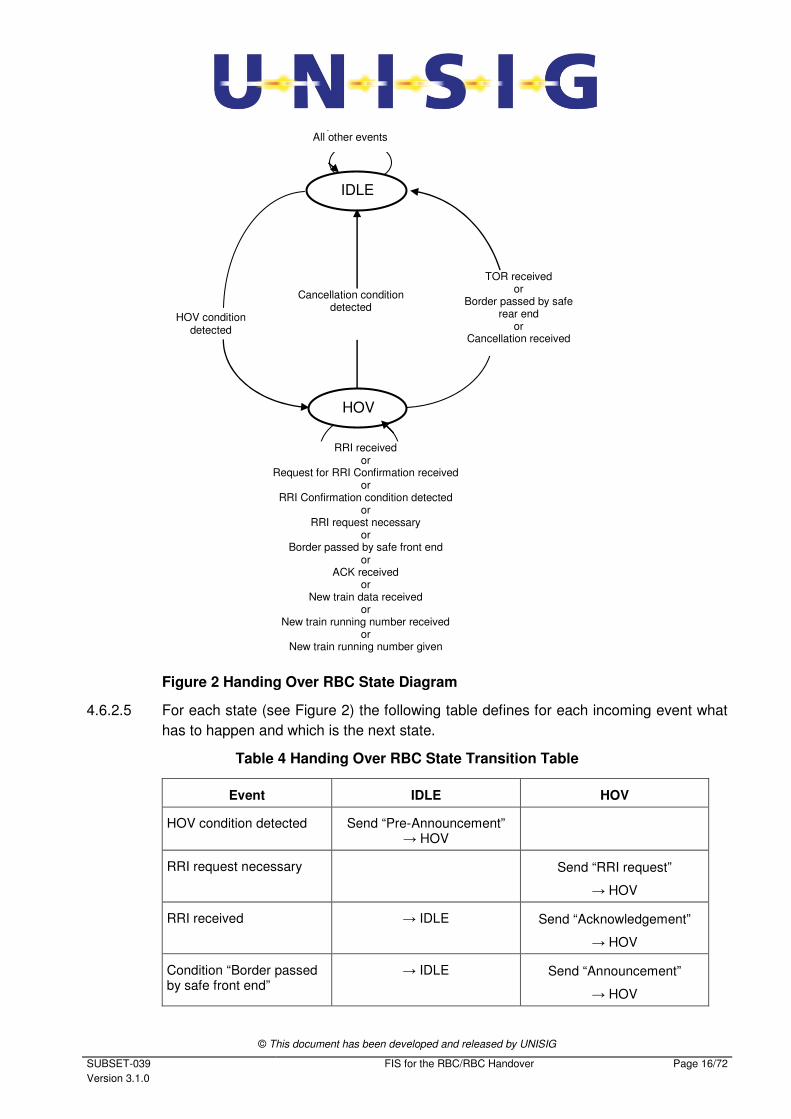
4.6.2.4 The following figure shows the state diagram of the Handing Over RBC:
a) The states (refer to Table 1)
b) The incoming events (refer to Table 2)
c) The state transitions.
© This document has been developed and released by UNISIG
SUBSET-039
Version 3.1.0
FIS for the RBC/RBC Handover Page 16/72
IDLE
HOV
Cancellation condition detected
HOV condition detected
TOR received or
Border passed by safe rear end
or Cancellation received
RRI received or
Request for RRI Confirmation received or
RRI Confirmation condition detected or
RRI request necessary or
Border passed by safe front end or
ACK received or
New train data received or
New train running number received or
New train running number given
All other events
Figure 2 Handing Over RBC State Diagram
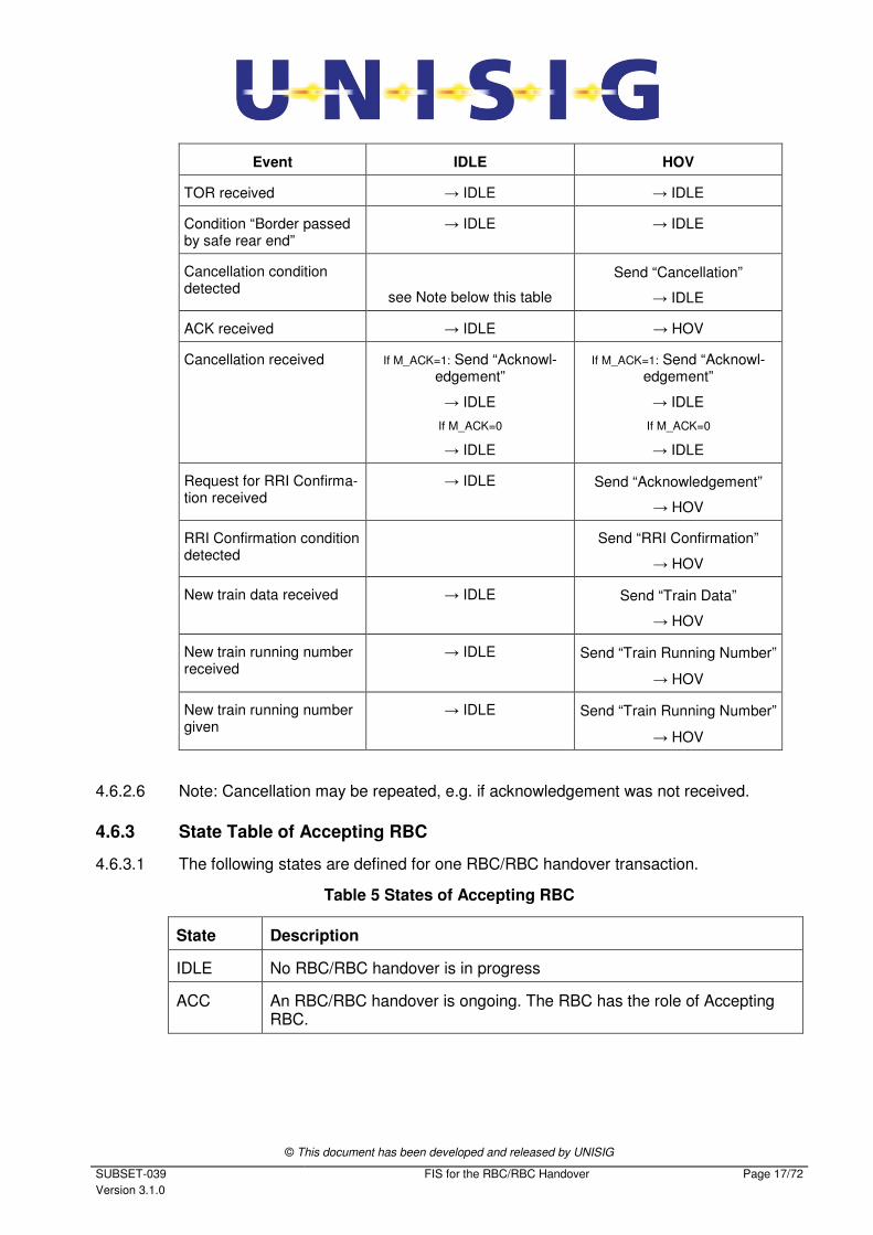
4.6.2.5 For each state (see Figure 2) the following table defines for each incoming event what
has to happen and which is the next state.
Table 4 Handing Over RBC State Transition Table
Event IDLE HOV
HOV condition detected Send “Pre-Announcement” → HOV
RRI request necessary Send “RRI request”
→ HOV
RRI received → IDLE Send “Acknowledgement”
→ HOV
Condition “Border passed by safe front end”
→ IDLE Send “Announcement”
→ HOV
© This document has been developed and released by UNISIG
SUBSET-039
Version 3.1.0
FIS for the RBC/RBC Handover Page 17/72
Event IDLE HOV
TOR received → IDLE → IDLE
Condition “Border passed by safe rear end”
→ IDLE → IDLE
Cancellation condition detected
see Note below this table
Send “Cancellation”
→ IDLE
ACK received → IDLE → HOV
Cancellation received If M_ACK=1: Send “Acknowl-edgement”
→ IDLE
If M_ACK=0
→ IDLE
If M_ACK=1: Send “Acknowl-edgement”
→ IDLE
If M_ACK=0
→ IDLE
Request for RRI Confirma-tion received
→ IDLE Send “Acknowledgement”
→ HOV
RRI Confirmation condition detected
Send “RRI Confirmation”
→ HOV
New train data received → IDLE Send “Train Data”
→ HOV
New train running number received
→ IDLE Send “Train Running Number”
→ HOV
New train running number given
→ IDLE Send “Train Running Number”
→ HOV
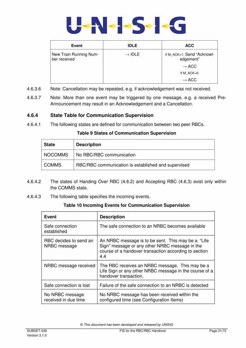
4.6.2.6 Note: Cancellation may be repeated, e.g. if acknowledgement was not received.
4.6.3 State Table of Accepting RBC
4.6.3.1 The following states are defined for one RBC/RBC handover transaction.
Table 5 States of Accepting RBC
State Description
IDLE No RBC/RBC handover is in progress
ACC An RBC/RBC handover is ongoing. The RBC has the role of Accepting RBC.
© This document has been developed and released by UNISIG
SUBSET-039
Version 3.1.0
FIS for the RBC/RBC Handover Page 18/72
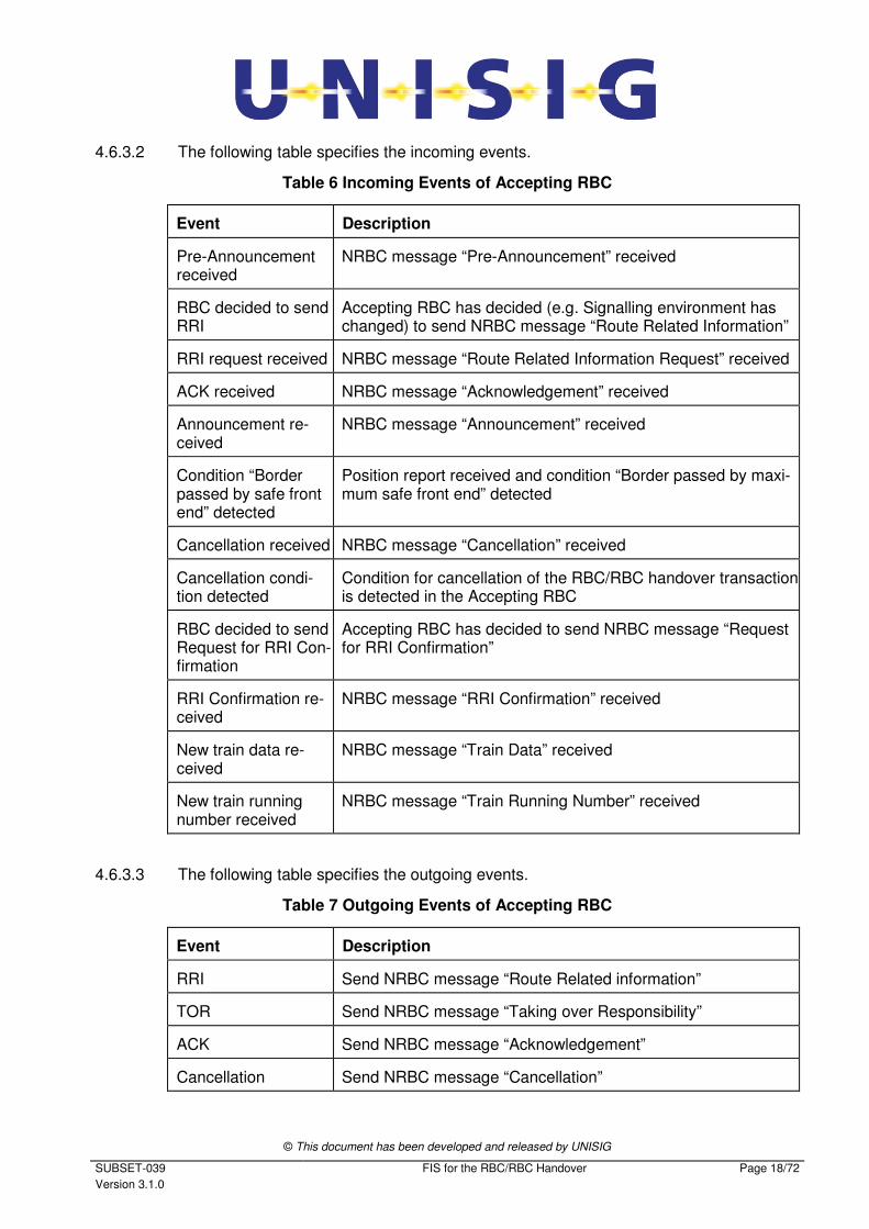
4.6.3.2 The following table specifies the incoming events.
Table 6 Incoming Events of Accepting RBC
Event Description
Pre-Announcement received
NRBC message “Pre-Announcement” received
RBC decided to send RRI
Accepting RBC has decided (e.g. Signalling environment has changed) to send NRBC message “Route Related Information”
RRI request received NRBC message “Route Related Information Request” received
ACK received NRBC message “Acknowledgement” received
Announcement re-ceived
NRBC message “Announcement” received
Condition “Border passed by safe front end” detected
Position report received and condition “Border passed by maxi-mum safe front end” detected
Cancellation received NRBC message “Cancellation” received
Cancellation condi-tion detected
Condition for cancellation of the RBC/RBC handover transaction is detected in the Accepting RBC
RBC decided to send Request for RRI Con-firmation
Accepting RBC has decided to send NRBC message “Request for RRI Confirmation”
RRI Confirmation re-ceived
NRBC message “RRI Confirmation” received
New train data re-ceived
NRBC message “Train Data” received
New train running number received
NRBC message “Train Running Number” received
4.6.3.3 The following table specifies the outgoing events.
Table 7 Outgoing Events of Accepting RBC
Event Description
RRI Send NRBC message “Route Related information”
TOR Send NRBC message “Taking over Responsibility”
ACK Send NRBC message “Acknowledgement”
Cancellation Send NRBC message “Cancellation”

© This document has been developed and released by UNISIG
SUBSET-039
Version 3.1.0
FIS for the RBC/RBC Handover Page 19/72
Event Description
Request for RRI Con-firmation
Send NRBC message “Request for RRI Confirmation”
4.6.3.4 The following figure shows the state diagram of the Accepting RBC.
a) The states (refer to Table 5)
b) The incoming events (refer to Table 6)
c) The state transitions
IDLE
ACC
Pre-Announcement received or
RBC decided to send RRI or
RBC decided to send Request for RRI Confirmation
or RRI request received
or ACK received
or Announcement received
or RRI Confirmation received
or New train data received
or New train running number received
All other events
Cancellation condition detected
Pre-Announcement received Border passed by safe
front end or
Cancellation received
Figure 3 Accepting RBC State Diagram
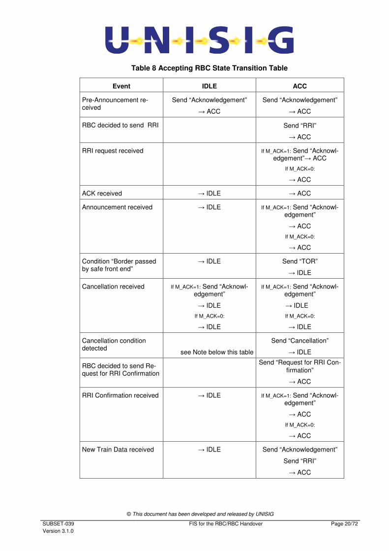
4.6.3.5 For each state (see Figure 3) the following table defines for each incoming event, what
has to happen and which is the next state.
© This document has been developed and released by UNISIG
SUBSET-039
Version 3.1.0
FIS for the RBC/RBC Handover Page 20/72
Table 8 Accepting RBC State Transition Table
Event IDLE ACC
Pre-Announcement re-ceived
Send “Acknowledgement”
→ ACC
Send “Acknowledgement”
→ ACC
RBC decided to send RRI Send “RRI”
→ ACC
RRI request received If M_ACK=1: Send “Acknowl-edgement”→ ACC
If M_ACK=0:
→ ACC
ACK received → IDLE → ACC
Announcement received → IDLE If M_ACK=1: Send “Acknowl-edgement”
→ ACC
If M_ACK=0:
→ ACC
Condition “Border passed by safe front end”
→ IDLE Send “TOR”
→ IDLE
Cancellation received If M_ACK=1: Send “Acknowl-edgement”
→ IDLE
If M_ACK=0:
→ IDLE
If M_ACK=1: Send “Acknowl-edgement”
→ IDLE
If M_ACK=0:
→ IDLE
Cancellation condition detected
see Note below this table
Send “Cancellation”
→ IDLE
RBC decided to send Re-quest for RRI Confirmation
Send “Request for RRI Con-
firmation”
→ ACC
RRI Confirmation received → IDLE If M_ACK=1: Send “Acknowl-edgement”
→ ACC
If M_ACK=0:
→ ACC
New Train Data received → IDLE
Send “Acknowledgement”
Send “RRI”
→ ACC
© This document has been developed and released by UNISIG
SUBSET-039
Version 3.1.0
FIS for the RBC/RBC Handover Page 21/72
Event IDLE ACC
New Train Running Num-ber received
→ IDLE
If M_ACK=1: Send “Acknowl-edgement”
→ ACC
If M_ACK=0:
→ ACC
4.6.3.6 Note: Cancellation may be repeated, e.g. if acknowledgement was not received.
4.6.3.7 Note: More than one event may be triggered by one message, e.g. a received Pre-
Announcement may result in an Acknowledgement and a Cancellation.
4.6.4 State Table for Communication Supervision
4.6.4.1 The following states are defined for communication between two peer RBCs.
Table 9 States of Communication Supervision
State Description
NOCOMMS No RBC/RBC communication
COMMS RBC/RBC communication is established and supervised
4.6.4.2 The states of Handing Over RBC (4.6.2) and Accepting RBC (4.6.3) exist only within
the COMMS state.
4.6.4.3 The following table specifies the incoming events.
Table 10 Incoming Events for Communication Supervision
Event Description
Safe connection established
The safe connection to an NRBC becomes available
RBC decides to send an NRBC message
An NRBC message is to be sent. This may be a “Life Sign” message or any other NRBC message in the course of a handover transaction according to section 4.4
NRBC message received The RBC receives an NRBC message. This may be a Life Sign or any other NRBC message in the course of a handover transaction.
Safe connection is lost Failure of the safe connection to an NRBC is detected
No NRBC message received in due time
No NRBC message has been received within the configured time (see Configuration Items)
© This document has been developed and released by UNISIG
SUBSET-039
Version 3.1.0
FIS for the RBC/RBC Handover Page 22/72
4.6.4.4 The following table specifies the outgoing events.
Table 11 Outgoing Events for Communication Supervision
Event Description
Send NRBC Message A Life Sign or other NRBC message (see 4.6.2.3 and 4.6.3.3) is sent
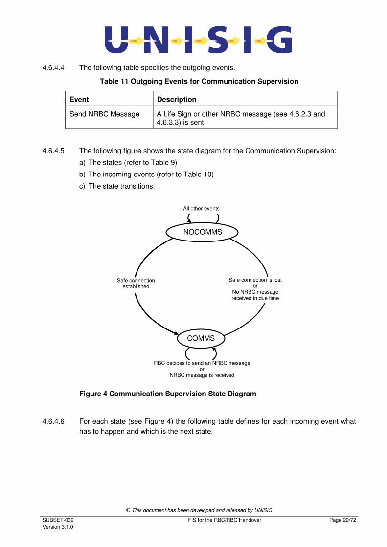
4.6.4.5 The following figure shows the state diagram for the Communication Supervision:
a) The states (refer to Table 9)
b) The incoming events (refer to Table 10)
c) The state transitions.
COMMS
All other events
Safe connection is lost or
No NRBC message received in due time
Safe connection established
RBC decides to send an NRBC message or
NRBC message is received
NOCOMMS
Figure 4 Communication Supervision State Diagram
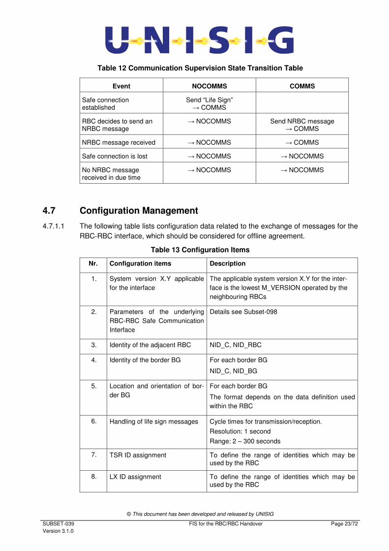
4.6.4.6 For each state (see Figure 4) the following table defines for each incoming event what
has to happen and which is the next state.
© This document has been developed and released by UNISIG
SUBSET-039
Version 3.1.0
FIS for the RBC/RBC Handover Page 23/72
Table 12 Communication Supervision State Transition Table
Event NOCOMMS COMMS
Safe connection established
Send “Life Sign” → COMMS
RBC decides to send an NRBC message
→ NOCOMMS Send NRBC message → COMMS
NRBC message received → NOCOMMS → COMMS
Safe connection is lost → NOCOMMS → NOCOMMS
No NRBC message received in due time
→ NOCOMMS → NOCOMMS
4.7 Configuration Management
4.7.1.1 The following table lists configuration data related to the exchange of messages for the
RBC-RBC interface, which should be considered for offline agreement.
Table 13 Configuration Items
Nr. Configuration items Description
1. System version X.Y applicable
for the interface
The applicable system version X.Y for the inter-
face is the lowest M_VERSION operated by the
neighbouring RBCs
2. Parameters of the underlying
RBC-RBC Safe Communication
Interface
Details see Subset-098
3. Identity of the adjacent RBC NID_C, NID_RBC
4. Identity of the border BG For each border BG
NID_C, NID_BG
5. Location and orientation of bor-
der BG
For each border BG
The format depends on the data definition used
within the RBC
6. Handling of life sign messages Cycle times for transmission/reception.
Resolution: 1 second
Range: 2 – 300 seconds
7. TSR ID assignment To define the range of identities which may be
used by the RBC
8. LX ID assignment To define the range of identities which may be
used by the RBC
© This document has been developed and released by UNISIG
SUBSET-039
Version 3.1.0
FIS for the RBC/RBC Handover Page 24/72
5. MESSAGES
5.1 General
5.1.1.1 The RBC/RBC handover ERTMS/ETCS language is based on variables, packets and
messages. This chapter re-uses some of the variables and packets specified for
transmission over other interfaces by [Subset-026 chapter 7].
5.1.1.2 New variables, which are required for NRBC messages, are specified in this document.
5.1.1.3 A NRBC message contains a header and an identified and coherent set of variables
and packets (if needed).
5.1.1.4 The behaviour of the receiver shall not depend on the sequence of the optional packets
given by the message.
5.1.1.5 The RBC shall reject a message transmitted from the NRBC if the message is not con-
sistent.
5.1.1.6 An NRBC message is consistent when all checks have been completed successfully:
a) Checks performed by RBC/RBC protocol have been passed (see [Subset-098])
b) Variables in the message do not have invalid values.
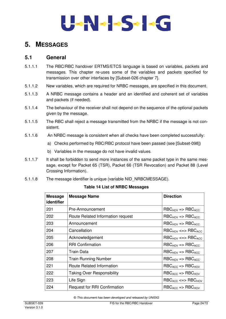
5.1.1.7 It shall be forbidden to send more instances of the same packet type in the same mes-
sage, except for Packet 65 (TSR), Packet 66 (TSR Revocation) and Packet 88 (Level
Crossing Information).
5.1.1.8 The message identifier is unique (variable NID_NRBCMESSAGE).
Table 14 List of NRBC Messages
Message
identifier
Message Name Direction
201 Pre-Announcement RBCHOV => RBCACC
202 Route Related Information request RBCHOV => RBCACC
203 Announcement RBCHOV => RBCACC
204 Cancellation RBCHOV <=> RBCACC
205 Acknowledgement RBCHOV <=> RBCACC
206 RRI Confirmation RBCHOV => RBCACC
207 Train Data RBCHOV => RBCACC
208 Train Running Number RBCHOV => RBCACC
221 Route Related Information RBCACC => RBCHOV
222 Taking Over Responsibility RBCACC => RBCHOV
223 Life Sign RBCACC <=> RBCHOV
224 Request for RRI Confirmation RBCACC => RBCHOV
© This document has been developed and released by UNISIG
SUBSET-039
Version 3.1.0
FIS for the RBC/RBC Handover Page 25/72
5.1.1.9 Each message includes the message length in bytes (variable L_MESSAGE).
5.1.1.10 If the computed length of the message is not equal to the length given by
L_MESSAGE, the entire message shall be rejected.
5.1.1.11 An NRBC message (except Life Sign) is identified for acknowledgement by
a) Identity of the sending RBC (variables NID_C and NID_RBC) and
b) Identity of the handed over engine (variable NID_ENGINE) and
c) Identity of the border BG (variables NID_C and NID_BG) and
d) Timestamp of the sending RBC (variable T_RBC).
5.1.1.12 Note: Non-unique identifiers for outstanding acknowledgements may have an impact
on system behaviour.
5.1.1.13 There shall always be a time stamp increment between consecutive messages. Wrap-
around of the RBC time stamp value can occur during an RBC/RBC session and shall
have no impact on system behaviour.
5.1.1.14 Note: This time stamp does not have to be based on real time.
5.1.1.15 The structure of a NRBC message (except Life Sign message) is shown by Figure 5.
Fields 1-9 form the header.
Field
No.
VARIABLE Remarks
1 NID_NRBCMESSAGE Message Identifier
2 L_MESSAGE Message length including everything (field 1 to padding)
3 NID_C Identity of the country or region (of the sending RBC)
4 NID_RBC Identity of the sending RBC
5 NID_ENGINE Identity of the handed over engine
6 NID_C Identity of the country or region (of the border balise group)
7 NID_BG Identity of border balise group
8 T_RBC Time stamp of sending RBC
9 M_ACK Qualifier for acknowledgement request
10 Variables as required
by
NID_NRBCMESSAGE
If needed for this message. Used when sending variables,
which are not included in a packet.
11 Packets as required
by
NID_NRBCMESSAGE
Padding Bit padding to octet borders, if required.
Figure 5 Structure of NRBC Messages
© This document has been developed and released by UNISIG
SUBSET-039
Version 3.1.0
FIS for the RBC/RBC Handover Page 26/72
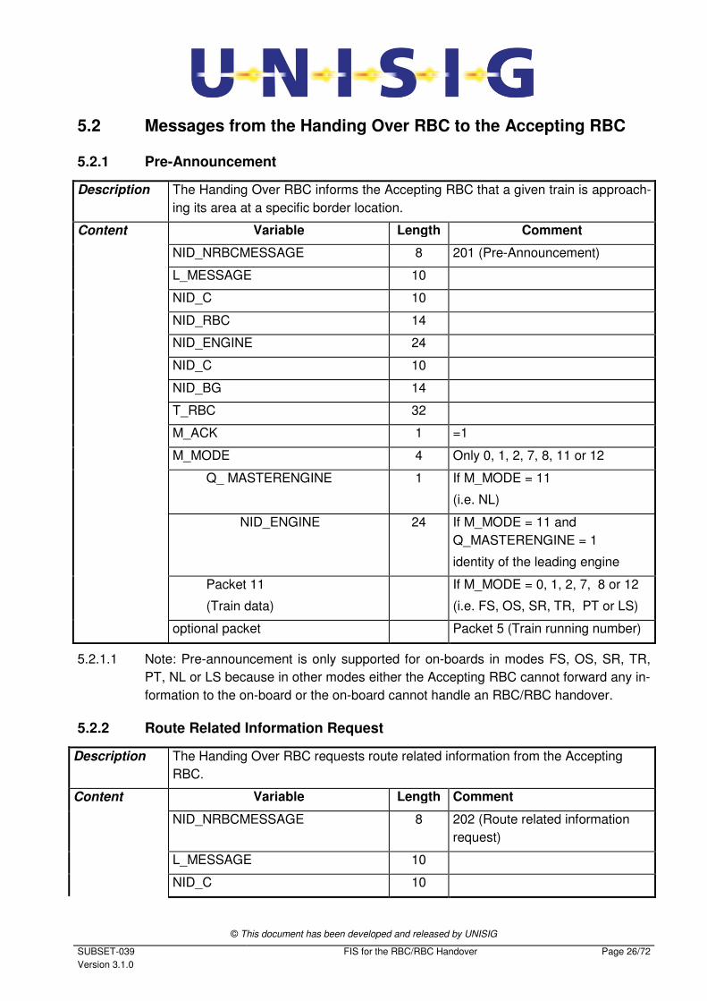
5.2 Messages from the Handing Over RBC to the Accepting RBC
5.2.1 Pre-Announcement
Description The Handing Over RBC informs the Accepting RBC that a given train is approach-
ing its area at a specific border location.
Content Variable Length Comment
NID_NRBCMESSAGE 8 201 (Pre-Announcement)
L_MESSAGE 10
NID_C 10
NID_RBC 14
NID_ENGINE 24
NID_C 10
NID_BG 14
T_RBC 32
M_ACK 1 =1
M_MODE 4 Only 0, 1, 2, 7, 8, 11 or 12
Q_ MASTERENGINE 1 If M_MODE = 11
(i.e. NL)
NID_ENGINE
24 If M_MODE = 11 and
Q_MASTERENGINE = 1
identity of the leading engine
Packet 11
(Train data)
If M_MODE = 0, 1, 2, 7, 8 or 12
(i.e. FS, OS, SR, TR, PT or LS)
optional packet Packet 5 (Train running number)
5.2.1.1 Note: Pre-announcement is only supported for on-boards in modes FS, OS, SR, TR,
PT, NL or LS because in other modes either the Accepting RBC cannot forward any in-
formation to the on-board or the on-board cannot handle an RBC/RBC handover.
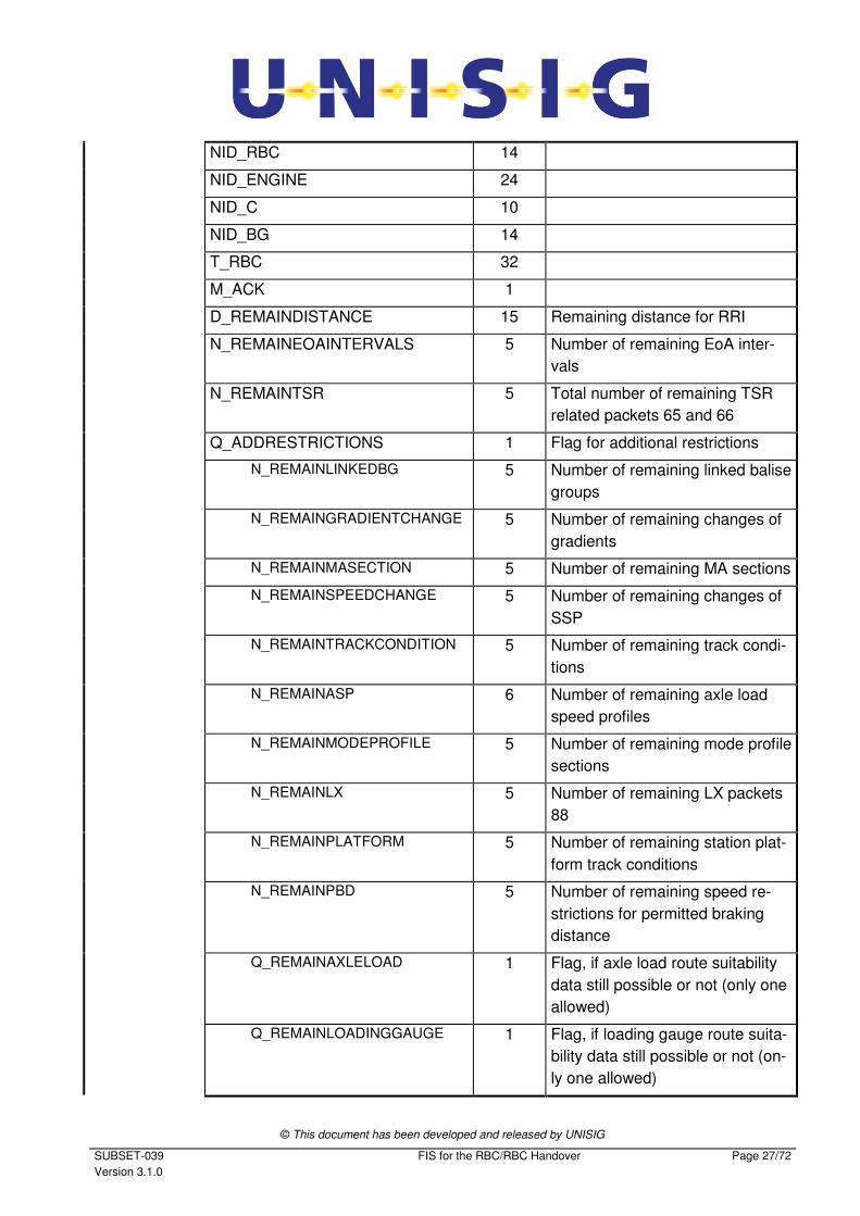
5.2.2 Route Related Information Request
Description The Handing Over RBC requests route related information from the Accepting
RBC.
Content Variable Length Comment
NID_NRBCMESSAGE 8 202 (Route related information
request)
L_MESSAGE 10
NID_C 10
© This document has been developed and released by UNISIG
SUBSET-039
Version 3.1.0
FIS for the RBC/RBC Handover Page 27/72
NID_RBC 14
NID_ENGINE 24
NID_C 10
NID_BG 14
T_RBC 32
M_ACK 1
D_REMAINDISTANCE 15 Remaining distance for RRI
N_REMAINEOAINTERVALS 5 Number of remaining EoA inter-
vals
N_REMAINTSR 5 Total number of remaining TSR
related packets 65 and 66
Q_ADDRESTRICTIONS 1 Flag for additional restrictions
N_REMAINLINKEDBG 5 Number of remaining linked balise
groups
N_REMAINGRADIENTCHANGE 5 Number of remaining changes of
gradients
N_REMAINMASECTION 5 Number of remaining MA sections
N_REMAINSPEEDCHANGE 5 Number of remaining changes of
SSP
N_REMAINTRACKCONDITION 5 Number of remaining track condi-
tions
N_REMAINASP 6 Number of remaining axle load
speed profiles
N_REMAINMODEPROFILE 5 Number of remaining mode profile
sections
N_REMAINLX 5 Number of remaining LX packets
88
N_REMAINPLATFORM 5 Number of remaining station plat-
form track conditions
N_REMAINPBD 5 Number of remaining speed re-
strictions for permitted braking
distance
Q_REMAINAXLELOAD 1 Flag, if axle load route suitability
data still possible or not (only one
allowed)
Q_REMAINLOADINGGAUGE 1 Flag, if loading gauge route suita-
bility data still possible or not (on-
ly one allowed)
© This document has been developed and released by UNISIG
SUBSET-039
Version 3.1.0
FIS for the RBC/RBC Handover Page 28/72
Q_REMAINTRACTION 1 Flag, if traction route suitability
data still possible or not (only one
allowed)
Q_REMAINLEVELTRANSITION 1 Flag, if level transition still possi-
ble or not
Q_REMAINTRACTIONSYSTEM
CHANGE
1 Flag, if traction system change
still possible or not
Q_REMAINCURRENT 1 Flag, if allowed current consump-
tion change still possible or not
5.2.2.1 Note: Parameters D_REMAINDISTANCE and N_REMAINEOAINTERVALS may be
used in combination.
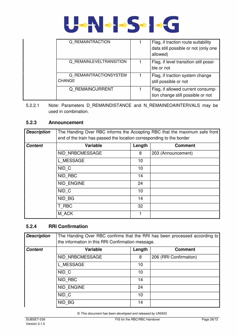
5.2.3 Announcement
Description The Handing Over RBC informs the Accepting RBC that the maximum safe front
end of the train has passed the location corresponding to the border
Content Variable Length Comment
NID_NRBCMESSAGE 8 203 (Announcement)
L_MESSAGE 10
NID_C 10
NID_RBC 14
NID_ENGINE 24
NID_C 10
NID_BG 14
T_RBC 32
M_ACK 1
5.2.4 RRI Confirmation
Description The Handing Over RBC confirms that the RRI has been processed according to
the information in this RRI Confirmation message.
Content Variable Length Comment
NID_NRBCMESSAGE 8 206 (RRI Confirmation)
L_MESSAGE 10
NID_C 10
NID_RBC 14
NID_ENGINE 24
NID_C 10
NID_BG 14
© This document has been developed and released by UNISIG
SUBSET-039
Version 3.1.0
FIS for the RBC/RBC Handover Page 29/72
T_RBC 32
M_ACK 1
T_RBCCONF 32 The timestamp of the Request for
RRI Confirmation message being
confirmed
Q_RRICONFSTATUS 2
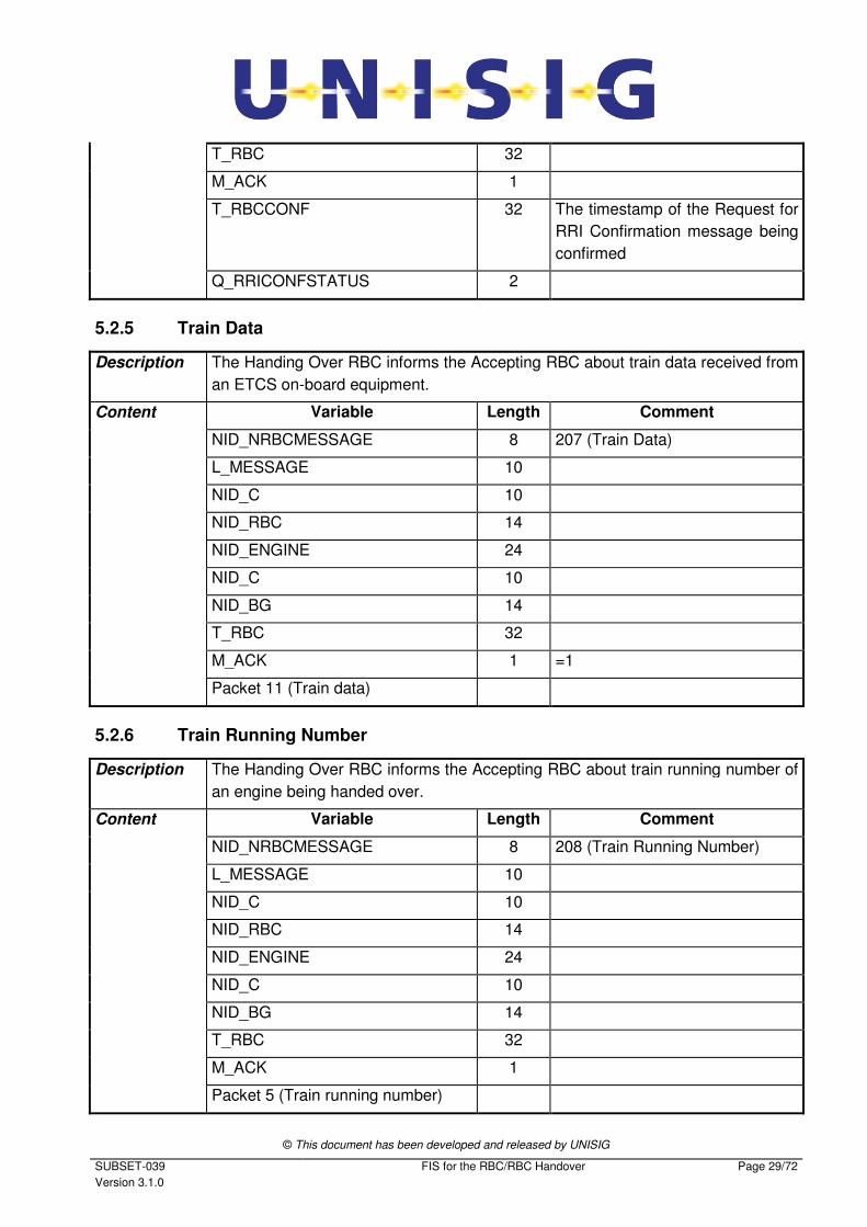
5.2.5 Train Data
Description The Handing Over RBC informs the Accepting RBC about train data received from
an ETCS on-board equipment.
Content Variable Length Comment
NID_NRBCMESSAGE 8 207 (Train Data)
L_MESSAGE 10
NID_C 10
NID_RBC 14
NID_ENGINE 24
NID_C 10
NID_BG 14
T_RBC 32
M_ACK 1 =1
Packet 11 (Train data)
5.2.6 Train Running Number
Description The Handing Over RBC informs the Accepting RBC about train running number of
an engine being handed over.
Content Variable Length Comment
NID_NRBCMESSAGE 8 208 (Train Running Number)
L_MESSAGE 10
NID_C 10
NID_RBC 14
NID_ENGINE 24
NID_C 10
NID_BG 14
T_RBC 32
M_ACK 1
Packet 5 (Train running number)
© This document has been developed and released by UNISIG
SUBSET-039
Version 3.1.0
FIS for the RBC/RBC Handover Page 30/72
5.3 Messages from the Accepting RBC to the Handing Over RBC
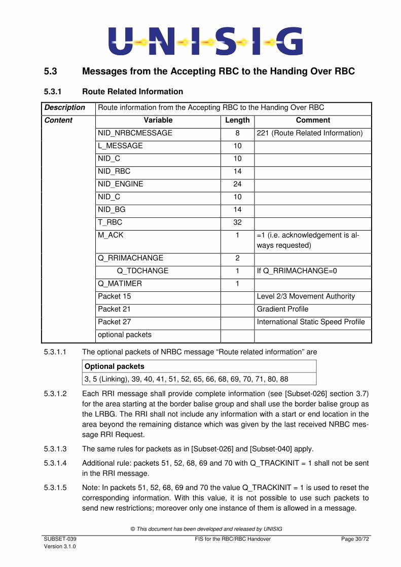
5.3.1 Route Related Information
Description Route information from the Accepting RBC to the Handing Over RBC
Content Variable Length Comment
NID_NRBCMESSAGE 8 221 (Route Related Information)
L_MESSAGE 10
NID_C 10
NID_RBC 14
NID_ENGINE 24
NID_C 10
NID_BG 14
T_RBC 32
M_ACK 1 =1 (i.e. acknowledgement is al-
ways requested)
Q_RRIMACHANGE 2
Q_TDCHANGE 1 If Q_RRIMACHANGE=0
Q_MATIMER 1
Packet 15 Level 2/3 Movement Authority
Packet 21 Gradient Profile
Packet 27 International Static Speed Profile
optional packets
5.3.1.1 The optional packets of NRBC message “Route related information” are
Optional packets
3, 5 (Linking), 39, 40, 41, 51, 52, 65, 66, 68, 69, 70, 71, 80, 88
5.3.1.2 Each RRI message shall provide complete information (see [Subset-026] section 3.7)
for the area starting at the border balise group and shall use the border balise group as
the LRBG. The RRI shall not include any information with a start or end location in the
area beyond the remaining distance which was given by the last received NRBC mes-
sage RRI Request.
5.3.1.3 The same rules for packets as in [Subset-026] and [Subset-040] apply.
5.3.1.4 Additional rule: packets 51, 52, 68, 69 and 70 with Q_TRACKINIT = 1 shall not be sent
in the RRI message.
5.3.1.5 Note: In packets 51, 52, 68, 69 and 70 the value Q_TRACKINIT = 1 is used to reset the
corresponding information. With this value, it is not possible to use such packets to
send new restrictions; moreover only one instance of them is allowed in a message.
© This document has been developed and released by UNISIG
SUBSET-039
Version 3.1.0
FIS for the RBC/RBC Handover Page 31/72
5.3.1.6 The total number of TSR related packets 65 and 66 in the RRI shall not exceed the
limit set by N_REMAINTSR in the last received RRI Request.
5.3.1.7 Note: It is a configuration issue to ensure that TSR identities are not duplicated. The
agreed value range for a specific RBC is applicable to both packet 65 and 66.
5.3.1.8 Note: It is a configuration issue to ensure that LX identities are not duplicated.
5.3.1.9 Note: Q_RRIMACHANGE and Q_TDCHANGE together with Q_MATIMER could help
the Handing Over RBC to determine the use of the received RRI information without
analysing the content of the individual packets.
5.3.1.10 The track description may also be changed if Q_RRIMACHANGE ≠ 0.
5.3.1.11 The status of Q_RRIMACHANGE indicating a shortened RRI shall be maintained until
an RRI message indicating the shortened status has been acknowledged by the Hand-
ing Over RBC.
5.3.1.12 The special/reserved value “Now” in the packets 3 (national values) and 41 (level tran-
sition order) shall not be sent in the RRI message.
5.3.1.13 The status of Q_TDCHANGE indicating a changed track data in the RRI shall be main-
tained until an RRI message indicating this changed track data has been acknowl-
edged by the Handing Over RBC.
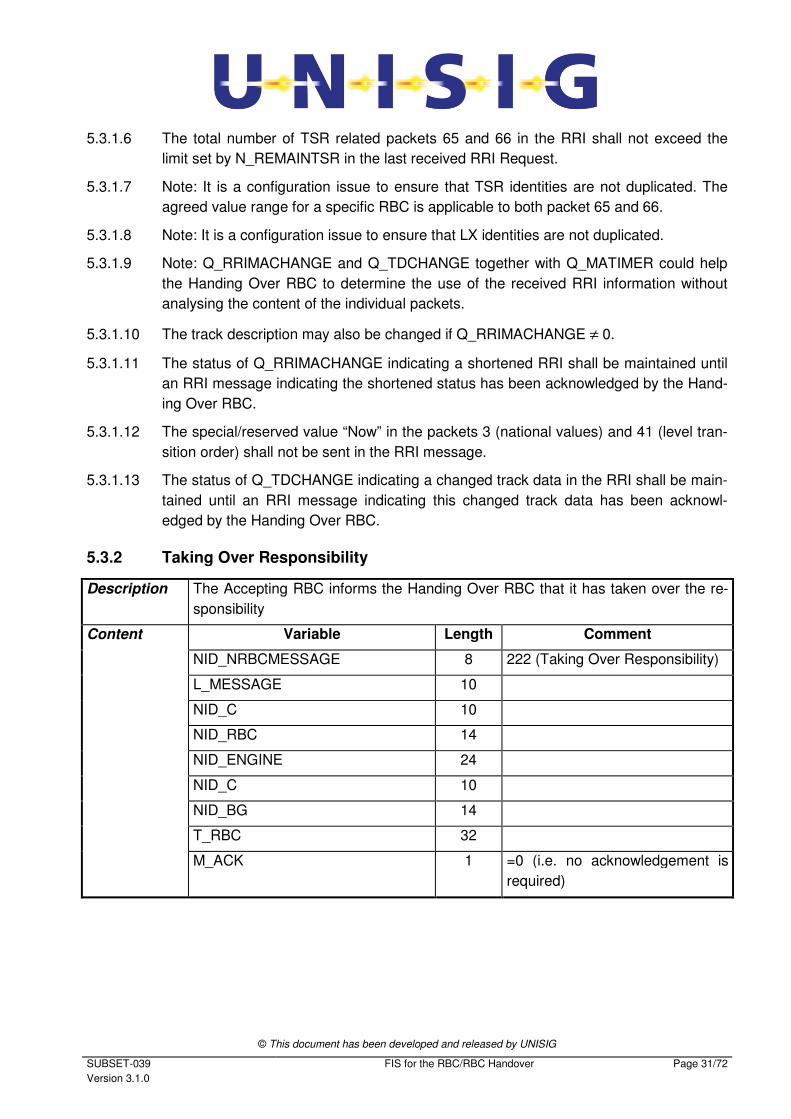
5.3.2 Taking Over Responsibility
Description The Accepting RBC informs the Handing Over RBC that it has taken over the re-
sponsibility
Content Variable Length Comment
NID_NRBCMESSAGE 8 222 (Taking Over Responsibility)
L_MESSAGE 10
NID_C 10
NID_RBC 14
NID_ENGINE 24
NID_C 10
NID_BG 14
T_RBC 32
M_ACK 1 =0 (i.e. no acknowledgement is
required)
© This document has been developed and released by UNISIG
SUBSET-039
Version 3.1.0
FIS for the RBC/RBC Handover Page 32/72
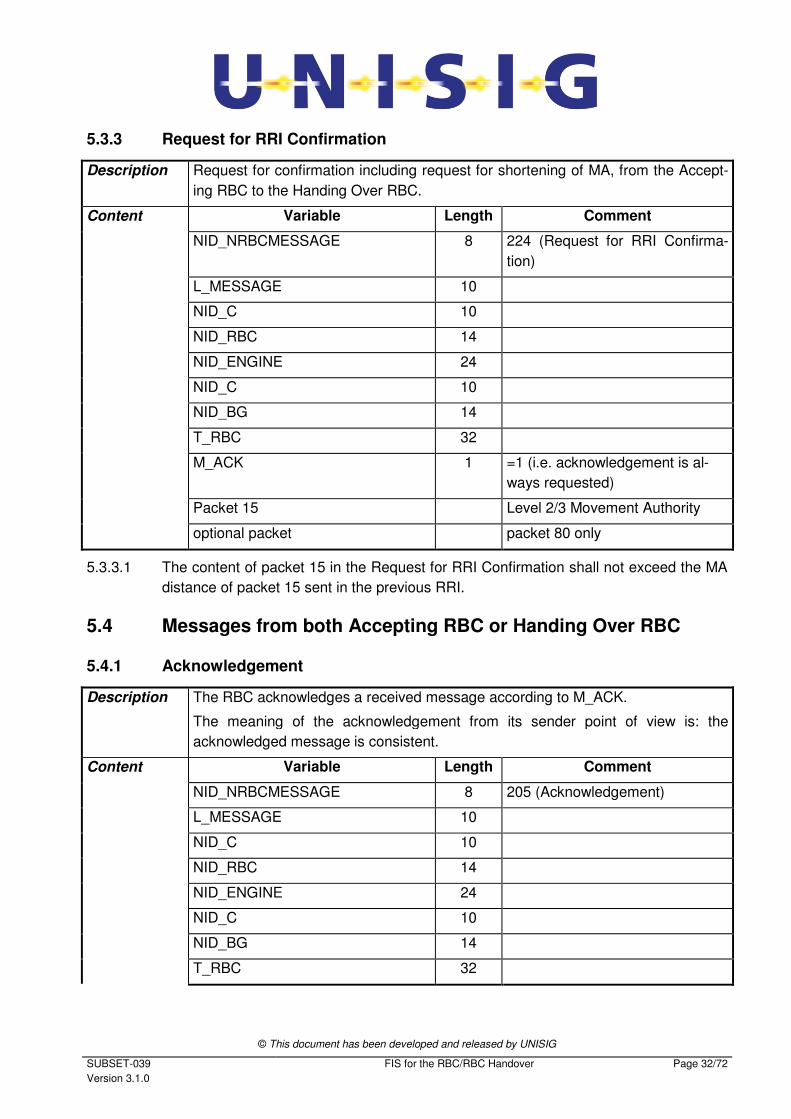
5.3.3 Request for RRI Confirmation
Description Request for confirmation including request for shortening of MA, from the Accept-
ing RBC to the Handing Over RBC.
Content Variable Length Comment
NID_NRBCMESSAGE 8 224 (Request for RRI Confirma-
tion)
L_MESSAGE 10
NID_C 10
NID_RBC 14
NID_ENGINE 24
NID_C 10
NID_BG 14
T_RBC 32
M_ACK 1 =1 (i.e. acknowledgement is al-
ways requested)
Packet 15 Level 2/3 Movement Authority
optional packet packet 80 only
5.3.3.1 The content of packet 15 in the Request for RRI Confirmation shall not exceed the MA
distance of packet 15 sent in the previous RRI.
5.4 Messages from both Accepting RBC or Handing Over RBC
5.4.1 Acknowledgement
Description The RBC acknowledges a received message according to M_ACK.
The meaning of the acknowledgement from its sender point of view is: the
acknowledged message is consistent.
Content Variable Length Comment
NID_NRBCMESSAGE 8 205 (Acknowledgement)
L_MESSAGE 10
NID_C 10
NID_RBC 14
NID_ENGINE 24
NID_C 10
NID_BG 14
T_RBC 32
© This document has been developed and released by UNISIG
SUBSET-039
Version 3.1.0
FIS for the RBC/RBC Handover Page 33/72
M_ACK 1 =0 (i.e. no acknowledgement is
required)
T_RBCACK 32 The timestamp of the message
being acknowledged
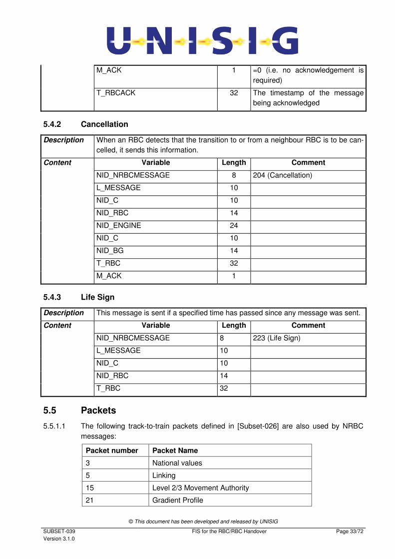
5.4.2 Cancellation
Description When an RBC detects that the transition to or from a neighbour RBC is to be can-
celled, it sends this information.
Content Variable Length Comment
NID_NRBCMESSAGE 8 204 (Cancellation)
L_MESSAGE 10
NID_C 10
NID_RBC 14
NID_ENGINE 24
NID_C 10
NID_BG 14
T_RBC 32
M_ACK 1
5.4.3 Life Sign
Description This message is sent if a specified time has passed since any message was sent.
Content Variable Length Comment
NID_NRBCMESSAGE 8 223 (Life Sign)
L_MESSAGE 10
NID_C 10
NID_RBC 14
T_RBC 32
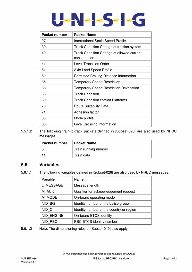
5.5 Packets
5.5.1.1 The following track-to-train packets defined in [Subset-026] are also used by NRBC
messages:
Packet number Packet Name
3 National values
5 Linking
15 Level 2/3 Movement Authority
21 Gradient Profile
© This document has been developed and released by UNISIG
SUBSET-039
Version 3.1.0
FIS for the RBC/RBC Handover Page 34/72
Packet number Packet Name
27 International Static Speed Profile
39 Track Condition Change of traction system
40 Track Condition Change of allowed current
consumption
41 Level Transition Order
51 Axle Load Speed Profile
52 Permitted Braking Distance Information
65 Temporary Speed Restriction
66 Temporary Speed Restriction Revocation
68 Track Condition
69 Track Condition Station Platforms
70 Route Suitability Data
71 Adhesion factor
80 Mode profile
88 Level Crossing information
5.5.1.2 The following train-to-track packets defined in [Subset-026] are also used by NRBC
messages:
Packet number Packet Name
5 Train running number
11 Train data
5.6 Variables
5.6.1.1 The following variables defined in [Subset-026] are also used by NRBC messages:
Variable Name
L_MESSAGE Message length
M_ACK Qualifier for acknowledgement request
M_MODE On-board operating mode
NID_BG Identity number of the balise group
NID_C Identity number of the country or region
NID_ENGINE On-board ETCS identity
NID_RBC RBC ETCS identity number
5.6.1.2 Note: The dimensioning rules of [Subset-040] also apply.
© This document has been developed and released by UNISIG
SUBSET-039
Version 3.1.0
FIS for the RBC/RBC Handover Page 35/72
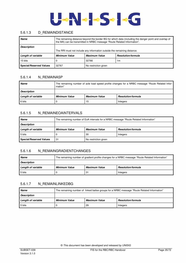
5.6.1.3 D_REMAINDISTANCE
Name The remaining distance beyond the border BG for which data (including the danger point and overlap of the MA) can be transmitted in NRBC message “Route Related Information”.
Description
The RRI must not include any information outside the remaining distance.
Length of variable Minimum Value Maximum Value Resolution/formula
15 bits 0 32766 1m
Special/Reserved Values 32767 No restriction given
5.6.1.4 N_REMAINASP
Name The remaining number of axle load speed profile changes for a NRBC message “Route Related Infor-mation”
Description
Length of variable Minimum Value Maximum Value Resolution/formula
6 bits 0 15 Integers
5.6.1.5 N_REMAINEOAINTERVALS
Name The remaining number of EoA intervals for a NRBC message “Route Related Information”
Description
Length of variable Minimum Value Maximum Value Resolution/formula
5 bits 0 30 Integers
Special/Reserved Values 31 No restriction given
5.6.1.6 N_REMAINGRADIENTCHANGES
Name The remaining number of gradient profile changes for a NRBC message “Route Related Information”
Description
Length of variable Minimum Value Maximum Value Resolution/formula
5 bits 0 31 Integers
5.6.1.7 N_REMAINLINKEDBG
Name The remaining number of linked balise groups for a NRBC message “Route Related Information”
Description
Length of variable Minimum Value Maximum Value Resolution/formula
5 bits 0 29 Integers
© This document has been developed and released by UNISIG
SUBSET-039
Version 3.1.0
FIS for the RBC/RBC Handover Page 36/72
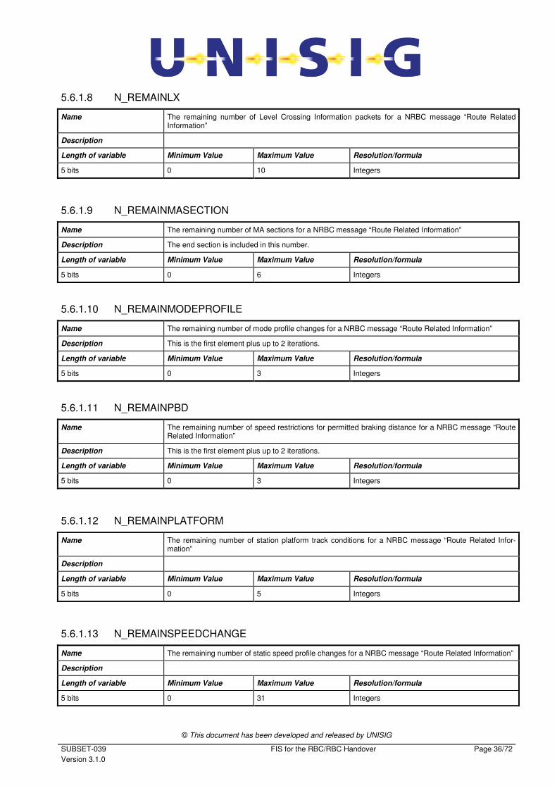
5.6.1.8 N_REMAINLX
Name The remaining number of Level Crossing Information packets for a NRBC message “Route Related Information”
Description
Length of variable Minimum Value Maximum Value Resolution/formula
5 bits 0 10 Integers
5.6.1.9 N_REMAINMASECTION
Name The remaining number of MA sections for a NRBC message “Route Related Information”
Description The end section is included in this number.
Length of variable Minimum Value Maximum Value Resolution/formula
5 bits 0 6 Integers
5.6.1.10 N_REMAINMODEPROFILE
Name The remaining number of mode profile changes for a NRBC message “Route Related Information”
Description This is the first element plus up to 2 iterations.
Length of variable Minimum Value Maximum Value Resolution/formula
5 bits 0 3 Integers
5.6.1.11 N_REMAINPBD
Name The remaining number of speed restrictions for permitted braking distance for a NRBC message “Route Related Information”
Description This is the first element plus up to 2 iterations.
Length of variable Minimum Value Maximum Value Resolution/formula
5 bits 0 3 Integers
5.6.1.12 N_REMAINPLATFORM
Name The remaining number of station platform track conditions for a NRBC message “Route Related Infor-mation”
Description
Length of variable Minimum Value Maximum Value Resolution/formula
5 bits 0 5 Integers
5.6.1.13 N_REMAINSPEEDCHANGE
Name The remaining number of static speed profile changes for a NRBC message “Route Related Information”
Description
Length of variable Minimum Value Maximum Value Resolution/formula
5 bits 0 31 Integers
© This document has been developed and released by UNISIG
SUBSET-039
Version 3.1.0
FIS for the RBC/RBC Handover Page 37/72
5.6.1.14 N_REMAINTRACKCOND
Name The remaining number of track condition for a NRBC message “Route Related Information”
Description This is the first element plus up to 19 iterations.
Length of variable Minimum Value Maximum Value Resolution/formula
5 bits 0 20 Integers
5.6.1.15 N_REMAINTSR
Name The remaining total number of temporary speed restriction and revocation packets for a NRBC message “Route Related Information”
Description
Length of variable Minimum Value Maximum Value Resolution/formula
5 bits 0 10 Integers
5.6.1.16 NID_NRBCMESSAGE
Name Message identifier
Description Identifier of a NRBC message
Length of variable Minimum Value Maximum Value Resolution/formula
8 bits 0 255 Numbers
Special/Reserved Values 201 Pre-Announcement
202 Route Related Information Request
203 Announcement
204 Cancellation
205 Acknowledgement
206 RRI Confirmation
207 Train Data
208 Train Running Number
221 Route Related Information
222 Taking Over Responsibility
223 Life Sign
224 Request for RRI Confirmation
5.6.1.17 Q_ADDRESTRICTIONS
Name Flag additional restrictions
Description
Length of variable Minimum Value Maximum Value Resolution/formula
1 bit
Special/Reserved Values 0 No further restrictions following
1 Further restrictions following
© This document has been developed and released by UNISIG
SUBSET-039
Version 3.1.0
FIS for the RBC/RBC Handover Page 38/72
5.6.1.18 Q_MASTERENGINE
Name Flag indication if the NID of the master engine is known
Description
Length of variable Minimum Value Maximum Value Resolution/formula
1 bit
Special/Reserved Values 0 No
1 Yes
5.6.1.19 Q_MATIMER
Name Flag indication if MA contains timers
Description
Length of variable Minimum Value Maximum Value Resolution/formula
1 bit
Special/Reserved Values 0 No
1 Yes
5.6.1.20 Q_REMAINAXLELOAD
Name Flag, if one route suitability data for axle load is possible or not
Description
Length of variable Minimum Value Maximum Value Resolution/formula
1 bit
Special/Reserved Values 0 No
1 Yes
5.6.1.21 Q_REMAINCURRENT
Name Flag, if change in allowed current consumption is possible or not
Description
Length of variable Minimum Value Maximum Value Resolution/formula
1 bit
Special/Reserved Values 0 No
1 Yes
5.6.1.22 Q_REMAINLEVELTRANSITION
Name Flag, if level transition still possible or not
Description
Length of variable Minimum Value Maximum Value Resolution/formula
1 bit
Special/Reserved Values 0 No
1 Yes
© This document has been developed and released by UNISIG
SUBSET-039
Version 3.1.0
FIS for the RBC/RBC Handover Page 39/72
5.6.1.23 Q_REMAINLOADINGGAUGE
Name Flag, if one route suitability data for loading gauge is possible or not
Description
Length of variable Minimum Value Maximum Value Resolution/formula
1 bit
Special/Reserved Values 0 No
1 Yes
5.6.1.24 Q_REMAINTRACTION
Name Flag, if one route suitability data for traction is possible or not
Description
Length of variable Minimum Value Maximum Value Resolution/formula
1 bit
Special/Reserved Values 0 No
1 Yes
5.6.1.25 Q_REMAINTRACTIONSYSTEMCHANGE
Name Flag, if traction system change still possible or not
Description
Length of variable Minimum Value Maximum Value Resolution/formula
1 bit
Special/Reserved Values 0 No
1 Yes
5.6.1.26 Q_RRICONFSTATUS
Name Status of RRI Confirmation
Description Indication whether the confirmation is negative or positive
Length of variable Minimum Value Maximum Value Resolution/formula
2 bit
Special/Reserved Values 0 No response from train, no further confirmation will be sent from RBCHOV
1 Not confirmed (negative)
2 Confirmed (positive)
3 Spare
© This document has been developed and released by UNISIG
SUBSET-039
Version 3.1.0
FIS for the RBC/RBC Handover Page 40/72
5.6.1.27 Q_RRIMACHANGE
Name Type of MA change
Description Relation of MA in the current RRI message to the MA in the last sent RRI message, if any.
Length of variable Minimum Value Maximum Value Resolution/formula
2 bits
Special/Reserved Values 0 Unchanged
1 Created
2 Extended
3 Shortened
5.6.1.28 Q_TDCHANGE
Name Change of track data
Description Indication whether the track data has changed in respect to the last sent RRI message, if any.
Track data applies to any packets in the RRI message except packet 15.
Length of variable Minimum Value Maximum Value Resolution/formula
1 bit
Special/Reserved Values 0 Not changed
1 Changed
5.6.1.29 T_RBC
Name Time stamp of sending RBC
Description Time stamp. It is used as unique identification for any message. The unit is count of 10ms, i.e. 4294967295 corresponds to 42949672.95s
Length of variable Minimum Value Maximum Value Resolution/formula
32 bits 0 4294967295 10 ms
5.6.1.30 T_RBCACK
Name The timestamp of the message being acknowledged.
Description The timestamp of the received message is used (together with Identification fields of the header) as unique identification of the message being acknowledged.
Length of variable Minimum Value Maximum Value Resolution/formula
32 bits 0 4294967295 10 ms
5.6.1.31 T_RBCCONF
Name The timestamp of the message being confirmed.
Description The timestamp of the received message is used (together with Identification fields of the header) as unique identification of the message being confirmed.
Length of variable Minimum Value Maximum Value Resolution/formula
32 bits 0 4294967295 10 ms
© This document has been developed and released by UNISIG
SUBSET-039
Version 3.1.0
FIS for the RBC/RBC Handover Page 41/72
6. MANAGEMENT OF OLDER SYSTEM VERSIONS
6.1 Scope
6.1.1.1 An RBC operating with a given ERTMS/ETCS system version shall support any of the
RBC/RBC languages defined in this document corresponding to the ERTMS/ETCS
system versions included in the envelope of legally operated system versions (see
Subset-026 clause 6.4), which are equal to or lower than its own ERTMS/ETCS system
version..
6.1.1.2 If two RBCs have different system versions X, the RBC operating with X=2 is responsi-
ble to translate the information exchanged over the interface:
- When forwarding it to an X=1 RBC, it must be translated from X=2 into X=1
- When receiving it from an X=1 RBC, it must be translated from X=1 into X=2
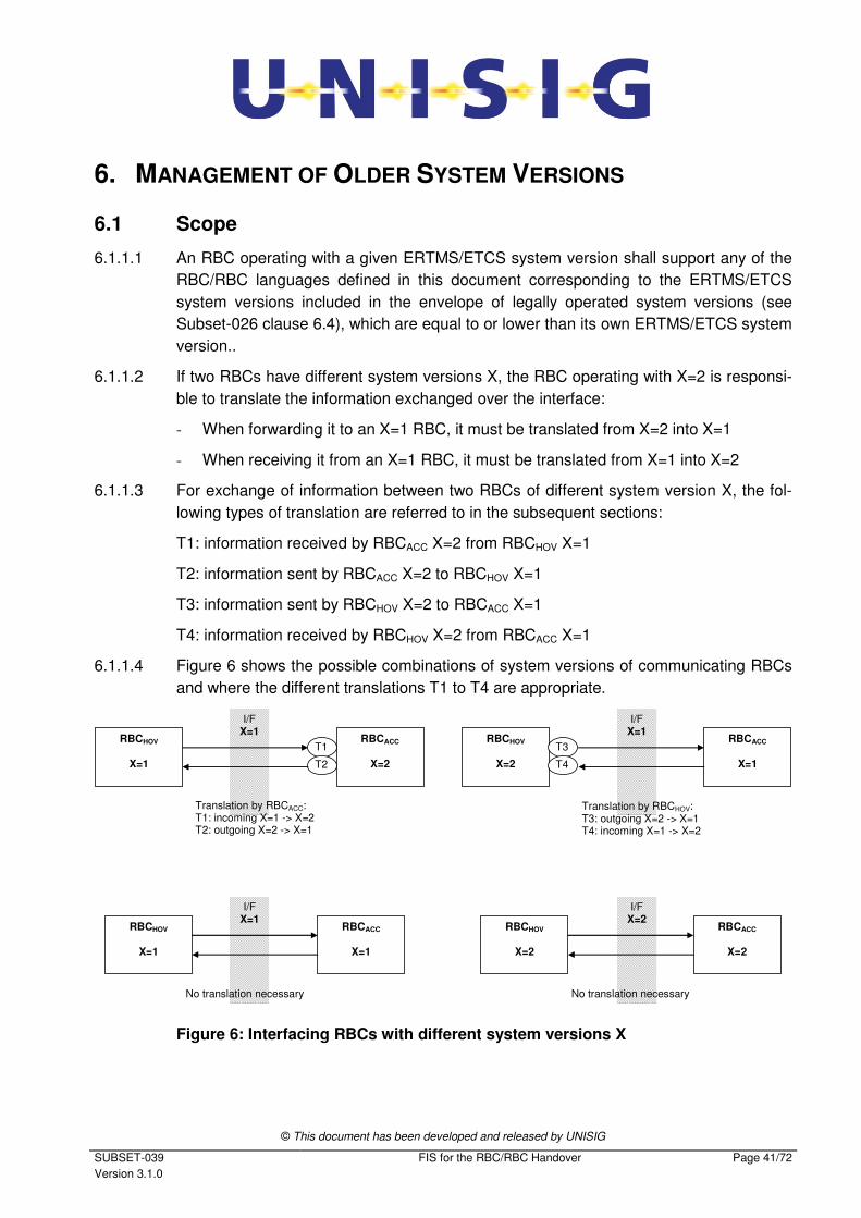
6.1.1.3 For exchange of information between two RBCs of different system version X, the fol-
lowing types of translation are referred to in the subsequent sections:
T1: information received by RBCACC X=2 from RBCHOV X=1
T2: information sent by RBCACC X=2 to RBCHOV X=1
T3: information sent by RBCHOV X=2 to RBCACC X=1
T4: information received by RBCHOV X=2 from RBCACC X=1
6.1.1.4 Figure 6 shows the possible combinations of system versions of communicating RBCs
and where the different translations T1 to T4 are appropriate.
RBCHOV
X=1
RBCACC
X=2
RBCHOV
X=2
RBCACC
X=1
RBCHOV
X=1
RBCACC
X=1
RBCHOV
X=2
RBCACC
X=2
I/F X=1
I/F X=1
I/F X=1
I/F X=2
T1
T2
T3
T4
Translation by RBCACC: T1: incoming X=1 -> X=2 T2: outgoing X=2 -> X=1
Translation by RBCHOV: T3: outgoing X=2 -> X=1 T4: incoming X=1 -> X=2
No translation necessary No translation necessary
Figure 6: Interfacing RBCs with different system versions X
© This document has been developed and released by UNISIG
SUBSET-039
Version 3.1.0
FIS for the RBC/RBC Handover Page 42/72
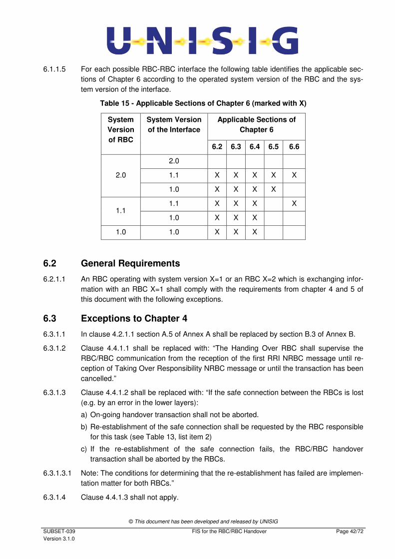
6.1.1.5 For each possible RBC-RBC interface the following table identifies the applicable sec-
tions of Chapter 6 according to the operated system version of the RBC and the sys-
tem version of the interface.
Table 15 - Applicable Sections of Chapter 6 (marked with X)
System
Version
of RBC
System Version
of the Interface
Applicable Sections of
Chapter 6
6.2 6.3 6.4 6.5 6.6
2.0
2.0
1.1 X X X X X
1.0 X X X X
1.1 1.1 X X X X
1.0 X X X
1.0 1.0 X X X
6.2 General Requirements
6.2.1.1 An RBC operating with system version X=1 or an RBC X=2 which is exchanging infor-
mation with an RBC X=1 shall comply with the requirements from chapter 4 and 5 of
this document with the following exceptions.
6.3 Exceptions to Chapter 4
6.3.1.1 In clause 4.2.1.1 section A.5 of Annex A shall be replaced by section B.3 of Annex B.
6.3.1.2 Clause 4.4.1.1 shall be replaced with: “The Handing Over RBC shall supervise the
RBC/RBC communication from the reception of the first RRI NRBC message until re-
ception of Taking Over Responsibility NRBC message or until the transaction has been
cancelled.”
6.3.1.3 Clause 4.4.1.2 shall be replaced with: “If the safe connection between the RBCs is lost
(e.g. by an error in the lower layers):
a) On-going handover transaction shall not be aborted.
b) Re-establishment of the safe connection shall be requested by the RBC responsible
for this task (see Table 13, list item 2)
c) If the re-establishment of the safe connection fails, the RBC/RBC handover
transaction shall be aborted by the RBCs.
6.3.1.3.1 Note: The conditions for determining that the re-establishment has failed are implemen-
tation matter for both RBCs.”
6.3.1.4 Clause 4.4.1.3 shall not apply.
© This document has been developed and released by UNISIG
SUBSET-039
Version 3.1.0
FIS for the RBC/RBC Handover Page 43/72
6.3.1.5 Clause 4.4.1.5 shall not apply.
6.3.1.6 Clause 4.4.1.6 shall be replaced with: “The Accepting RBC shall send an appropriate
NRBC message when a handover transaction is ongoing and a specified time has
passed since any NRBC message was sent.”
6.3.1.7 Clauses 4.4.1.7 and 4.4.1.7.1 shall not apply.
6.3.1.8 Clause 4.5.1.7 shall not apply.
6.3.1.9 Section 4.6.2 shall be replaced with section B.1 from Annex B.
6.3.1.10 Section 4.6.3 shall be replaced with section B.2 from Annex B.
6.3.1.11 Section 4.6.4 shall not apply.
6.3.1.12 In Table 13, configuration item 8 [LX ID assignment] shall not apply.
6.4 Exceptions to Chapter 5
6.4.1.1 Added clause 5.1.1.1.1 shall apply: “All relevant exceptions for packet structures and
variable definitions specified in [Subset-026 section 6.5.1.5] shall apply as well as the
exception for the structure of packet 11 specified in [Subset-026 section 6.6.3.4].”
6.4.1.2 Clause 5.1.1.7 shall be replaced with: “It shall be forbidden to send more instances of
the same packet type in the same message, except for Packet 65 (TSR) and Packet 66
(TSR Revocation).”
6.4.1.3 In Table 14, message with identifier 208 shall not apply.
6.4.1.4 In Table 14, message with identifier 223 shall only be valid for direction RBCACC to
RBCHOV.
6.4.1.5 In clause 5.1.1.11, the exception “except for Life Sign” shall not apply.
6.4.1.6 In clause 5.1.1.15, the exception “except Life Sign message” shall not apply.
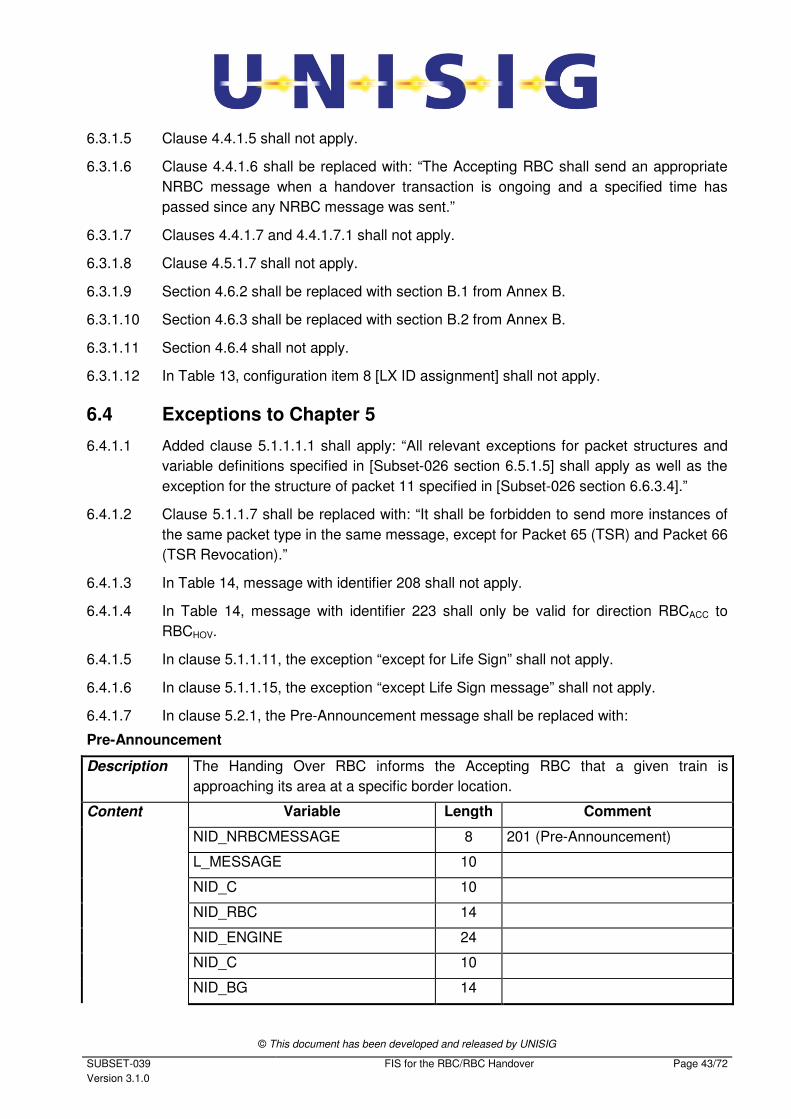
6.4.1.7 In clause 5.2.1, the Pre-Announcement message shall be replaced with:
Pre-Announcement
Description The Handing Over RBC informs the Accepting RBC that a given train is
approaching its area at a specific border location.
Content Variable Length Comment
NID_NRBCMESSAGE 8 201 (Pre-Announcement)
L_MESSAGE 10
NID_C 10
NID_RBC 14
NID_ENGINE 24
NID_C 10
NID_BG 14
© This document has been developed and released by UNISIG
SUBSET-039
Version 3.1.0
FIS for the RBC/RBC Handover Page 44/72
T_RBC 32
M_ACK 1 =1
M_MODE 4 Only 0, 1, 2, 7, 8, 11 or 12
Q_ MASTERENGINE 1 If M_MODE = 11
(i.e. NL)
NID_ENGINE
24 If M_MODE = 11 and
Q_MASTERENGINE = 1
identity of the leading engine
Packet 11
(Train data)
If M_MODE = 0, 1, 2, 7, 8 or 12
(i.e. FS, OS, SR, TR, PT or LS)
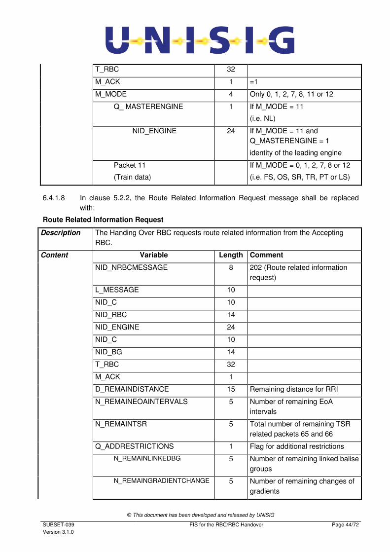
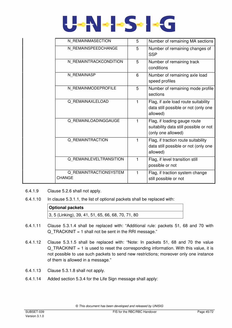
6.4.1.8 In clause 5.2.2, the Route Related Information Request message shall be replaced
with:
Route Related Information Request
Description The Handing Over RBC requests route related information from the Accepting
RBC.
Content Variable Length Comment
NID_NRBCMESSAGE 8 202 (Route related information
request)
L_MESSAGE 10
NID_C 10
NID_RBC 14
NID_ENGINE 24
NID_C 10
NID_BG 14
T_RBC 32
M_ACK 1
D_REMAINDISTANCE 15 Remaining distance for RRI
N_REMAINEOAINTERVALS 5 Number of remaining EoA
intervals
N_REMAINTSR 5 Total number of remaining TSR
related packets 65 and 66
Q_ADDRESTRICTIONS 1 Flag for additional restrictions
N_REMAINLINKEDBG 5 Number of remaining linked balise
groups
N_REMAINGRADIENTCHANGE 5 Number of remaining changes of
gradients
© This document has been developed and released by UNISIG
SUBSET-039
Version 3.1.0
FIS for the RBC/RBC Handover Page 45/72
N_REMAINMASECTION 5 Number of remaining MA sections
N_REMAINSPEEDCHANGE 5 Number of remaining changes of
SSP
N_REMAINTRACKCONDITION 5 Number of remaining track
conditions
N_REMAINASP 6 Number of remaining axle load
speed profiles
N_REMAINMODEPROFILE 5 Number of remaining mode profile
sections
Q_REMAINAXLELOAD 1 Flag, if axle load route suitability
data still possible or not (only one
allowed)
Q_REMAINLOADINGGAUGE 1 Flag, if loading gauge route
suitability data still possible or not
(only one allowed)
Q_REMAINTRACTION 1 Flag, if traction route suitability
data still possible or not (only one
allowed)
Q_REMAINLEVELTRANSITION 1 Flag, if level transition still
possible or not
Q_REMAINTRACTIONSYSTEM
CHANGE
1 Flag, if traction system change
still possible or not
6.4.1.9 Clause 5.2.6 shall not apply.
6.4.1.10 In clause 5.3.1.1, the list of optional packets shall be replaced with:
Optional packets
3, 5 (Linking), 39, 41, 51, 65, 66, 68, 70, 71, 80
6.4.1.11 Clause 5.3.1.4 shall be replaced with: “Additional rule: packets 51, 68 and 70 with
Q_TRACKINIT = 1 shall not be sent in the RRI message.”
6.4.1.12 Clause 5.3.1.5 shall be replaced with: “Note: In packets 51, 68 and 70 the value
Q_TRACKINIT = 1 is used to reset the corresponding information. With this value, it is
not possible to use such packets to send new restrictions; moreover only one instance
of them is allowed in a message.”
6.4.1.13 Clause 5.3.1.8 shall not apply.
6.4.1.14 Added section 5.3.4 for the Life Sign message shall apply:
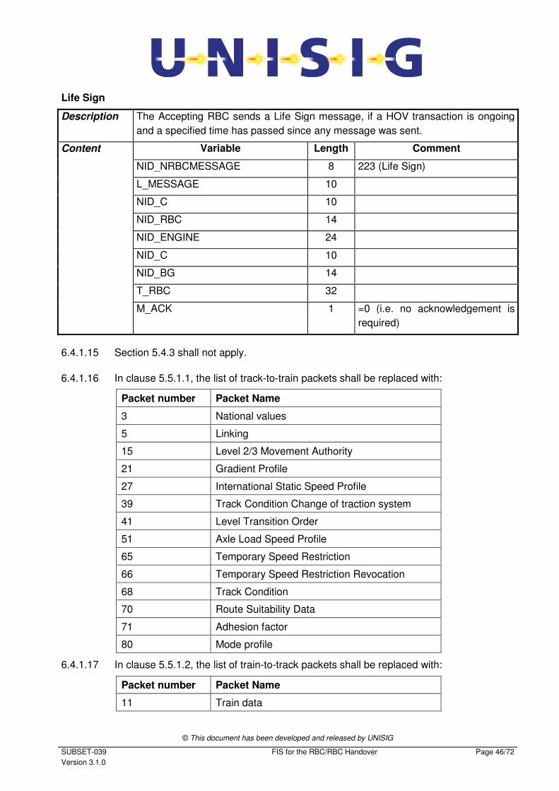
© This document has been developed and released by UNISIG
SUBSET-039
Version 3.1.0
FIS for the RBC/RBC Handover Page 46/72
Life Sign
Description The Accepting RBC sends a Life Sign message, if a HOV transaction is ongoing
and a specified time has passed since any message was sent.
Content Variable Length Comment
NID_NRBCMESSAGE 8 223 (Life Sign)
L_MESSAGE 10
NID_C 10
NID_RBC 14
NID_ENGINE 24
NID_C 10
NID_BG 14
T_RBC 32
M_ACK 1 =0 (i.e. no acknowledgement is
required)
6.4.1.15 Section 5.4.3 shall not apply.
6.4.1.16 In clause 5.5.1.1, the list of track-to-train packets shall be replaced with:
Packet number Packet Name
3 National values
5 Linking
15 Level 2/3 Movement Authority
21 Gradient Profile
27 International Static Speed Profile
39 Track Condition Change of traction system
41 Level Transition Order
51 Axle Load Speed Profile
65 Temporary Speed Restriction
66 Temporary Speed Restriction Revocation
68 Track Condition
70 Route Suitability Data
71 Adhesion factor
80 Mode profile
6.4.1.17 In clause 5.5.1.2, the list of train-to-track packets shall be replaced with:
Packet number Packet Name
11 Train data
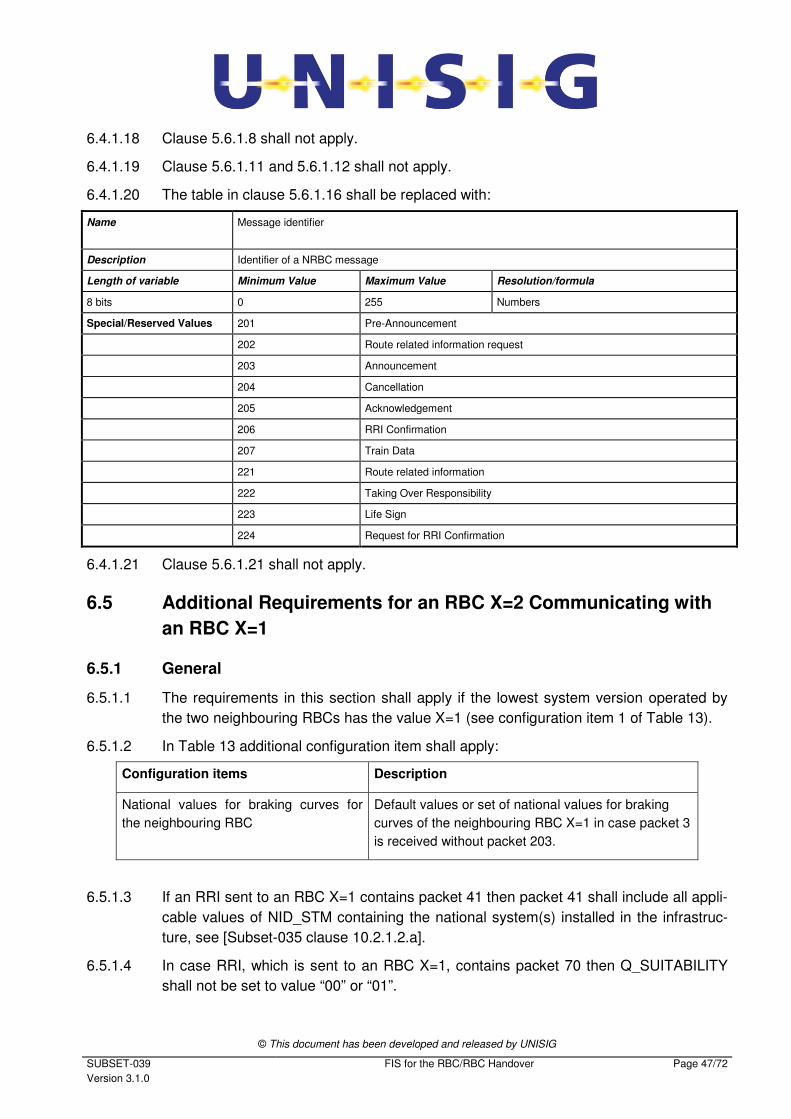
© This document has been developed and released by UNISIG
SUBSET-039
Version 3.1.0
FIS for the RBC/RBC Handover Page 47/72
6.4.1.18 Clause 5.6.1.8 shall not apply.
6.4.1.19 Clause 5.6.1.11 and 5.6.1.12 shall not apply.
6.4.1.20 The table in clause 5.6.1.16 shall be replaced with:
Name Message identifier
Description Identifier of a NRBC message
Length of variable Minimum Value Maximum Value Resolution/formula
8 bits 0 255 Numbers
Special/Reserved Values 201 Pre-Announcement
202 Route related information request
203 Announcement
204 Cancellation
205 Acknowledgement
206 RRI Confirmation
207 Train Data
221 Route related information
222 Taking Over Responsibility
223 Life Sign
224 Request for RRI Confirmation
6.4.1.21 Clause 5.6.1.21 shall not apply.
6.5 Additional Requirements for an RBC X=2 Communicating with
an RBC X=1
6.5.1 General
6.5.1.1 The requirements in this section shall apply if the lowest system version operated by
the two neighbouring RBCs has the value X=1 (see configuration item 1 of Table 13).
6.5.1.2 In Table 13 additional configuration item shall apply:
Configuration items Description
National values for braking curves for
the neighbouring RBC
Default values or set of national values for braking
curves of the neighbouring RBC X=1 in case packet 3
is received without packet 203.
6.5.1.3 If an RRI sent to an RBC X=1 contains packet 41 then packet 41 shall include all appli-
cable values of NID_STM containing the national system(s) installed in the infrastruc-
ture, see [Subset-035 clause 10.2.1.2.a].
6.5.1.4 In case RRI, which is sent to an RBC X=1, contains packet 70 then Q_SUITABILITY
shall not be set to value “00” or “01”.
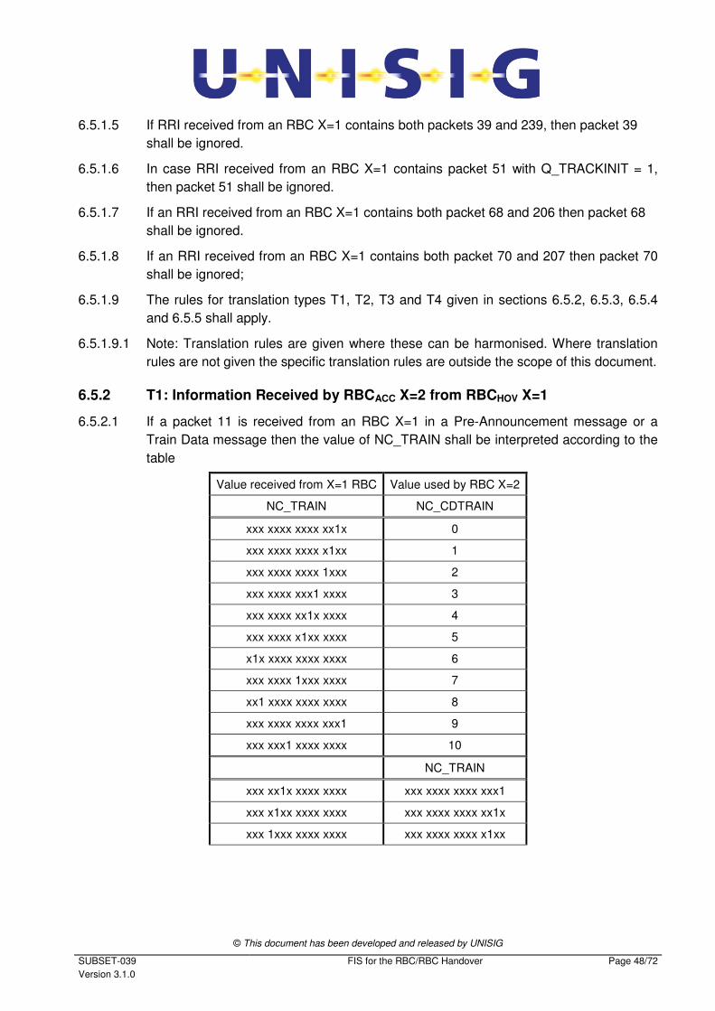
© This document has been developed and released by UNISIG
SUBSET-039
Version 3.1.0
FIS for the RBC/RBC Handover Page 48/72
6.5.1.5 If RRI received from an RBC X=1 contains both packets 39 and 239, then packet 39
shall be ignored.
6.5.1.6 In case RRI received from an RBC X=1 contains packet 51 with Q_TRACKINIT = 1,
then packet 51 shall be ignored.
6.5.1.7 If an RRI received from an RBC X=1 contains both packet 68 and 206 then packet 68
shall be ignored.
6.5.1.8 If an RRI received from an RBC X=1 contains both packet 70 and 207 then packet 70
shall be ignored;
6.5.1.9 The rules for translation types T1, T2, T3 and T4 given in sections 6.5.2, 6.5.3, 6.5.4
and 6.5.5 shall apply.
6.5.1.9.1 Note: Translation rules are given where these can be harmonised. Where translation
rules are not given the specific translation rules are outside the scope of this document.
6.5.2 T1: Information Received by RBCACC X=2 from RBCHOV X=1
6.5.2.1 If a packet 11 is received from an RBC X=1 in a Pre-Announcement message or a
Train Data message then the value of NC_TRAIN shall be interpreted according to the
table
Value received from X=1 RBC Value used by RBC X=2
NC_TRAIN NC_CDTRAIN
xxx xxxx xxxx xx1x 0
xxx xxxx xxxx x1xx 1
xxx xxxx xxxx 1xxx 2
xxx xxxx xxx1 xxxx 3
xxx xxxx xx1x xxxx 4
xxx xxxx x1xx xxxx 5
x1x xxxx xxxx xxxx 6
xxx xxxx 1xxx xxxx 7
xx1 xxxx xxxx xxxx 8
xxx xxxx xxxx xxx1 9
xxx xxx1 xxxx xxxx 10
NC_TRAIN
xxx xx1x xxxx xxxx xxx xxxx xxxx xxx1
xxx x1xx xxxx xxxx xxx xxxx xxxx xx1x
xxx 1xxx xxxx xxxx xxx xxxx xxxx x1xx
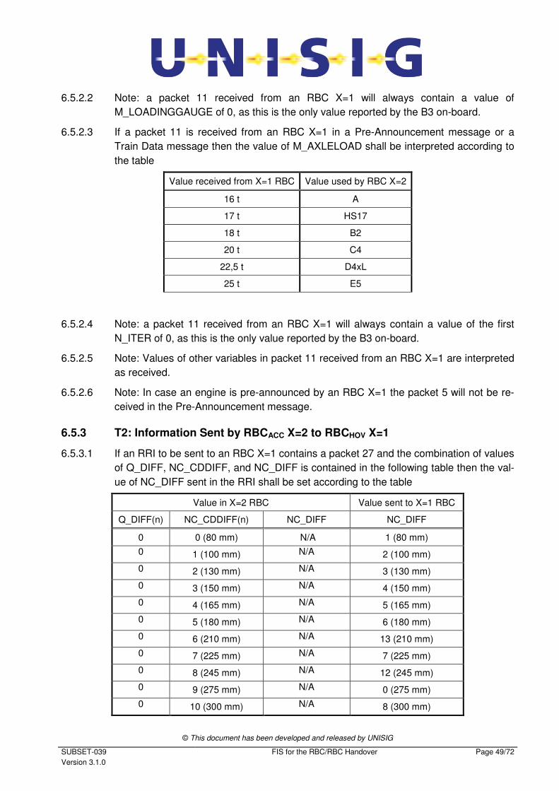
© This document has been developed and released by UNISIG
SUBSET-039
Version 3.1.0
FIS for the RBC/RBC Handover Page 49/72
6.5.2.2 Note: a packet 11 received from an RBC X=1 will always contain a value of
M_LOADINGGAUGE of 0, as this is the only value reported by the B3 on-board.
6.5.2.3 If a packet 11 is received from an RBC X=1 in a Pre-Announcement message or a
Train Data message then the value of M_AXLELOAD shall be interpreted according to
the table
Value received from X=1 RBC Value used by RBC X=2
16 t A
17 t HS17
18 t B2
20 t C4
22,5 t D4xL
25 t E5
6.5.2.4 Note: a packet 11 received from an RBC X=1 will always contain a value of the first
N_ITER of 0, as this is the only value reported by the B3 on-board.
6.5.2.5 Note: Values of other variables in packet 11 received from an RBC X=1 are interpreted
as received.
6.5.2.6 Note: In case an engine is pre-announced by an RBC X=1 the packet 5 will not be re-
ceived in the Pre-Announcement message.
6.5.3 T2: Information Sent by RBCACC X=2 to RBCHOV X=1
6.5.3.1 If an RRI to be sent to an RBC X=1 contains a packet 27 and the combination of values
of Q_DIFF, NC_CDDIFF, and NC_DIFF is contained in the following table then the val-
ue of NC_DIFF sent in the RRI shall be set according to the table
Value in X=2 RBC Value sent to X=1 RBC
Q_DIFF(n) NC_CDDIFF(n) NC_DIFF NC_DIFF
0 0 (80 mm) N/A 1 (80 mm)
0 1 (100 mm) N/A 2 (100 mm)
0 2 (130 mm) N/A 3 (130 mm)
0 3 (150 mm) N/A 4 (150 mm)
0 4 (165 mm) N/A 5 (165 mm)
0 5 (180 mm) N/A 6 (180 mm)
0 6 (210 mm) N/A 13 (210 mm)
0 7 (225 mm) N/A 7 (225 mm)
0 8 (245 mm) N/A 12 (245 mm)
0 9 (275 mm) N/A 0 (275 mm)
0 10 (300 mm) N/A 8 (300 mm)
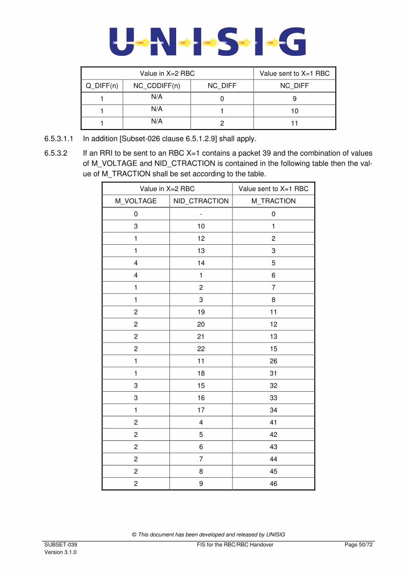
© This document has been developed and released by UNISIG
SUBSET-039
Version 3.1.0
FIS for the RBC/RBC Handover Page 50/72
Value in X=2 RBC Value sent to X=1 RBC
Q_DIFF(n) NC_CDDIFF(n) NC_DIFF NC_DIFF
1 N/A 0 9
1 N/A 1 10
1 N/A 2 11
6.5.3.1.1 In addition [Subset-026 clause 6.5.1.2.9] shall apply.
6.5.3.2 If an RRI to be sent to an RBC X=1 contains a packet 39 and the combination of values
of M_VOLTAGE and NID_CTRACTION is contained in the following table then the val-
ue of M_TRACTION shall be set according to the table.
Value in X=2 RBC Value sent to X=1 RBC
M_VOLTAGE NID_CTRACTION M_TRACTION
0 - 0
3 10 1
1 12 2
1 13 3
4 14 5
4 1 6
1 2 7
1 3 8
2 19 11
2 20 12
2 21 13
2 22 15
1 11 26
1 18 31
3 15 32
3 16 33
1 17 34
2 4 41
2 5 42
2 6 43
2 7 44
2 8 45
2 9 46
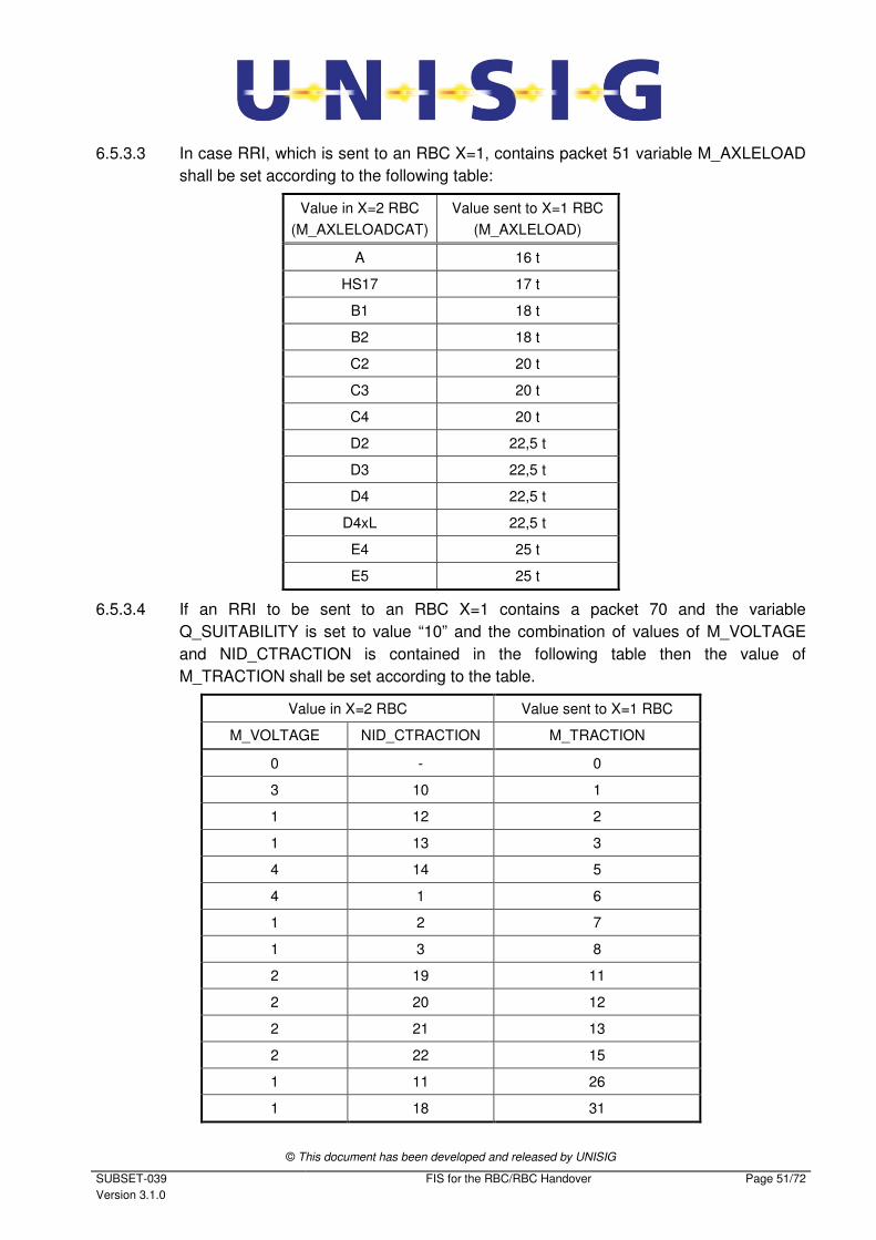
© This document has been developed and released by UNISIG
SUBSET-039
Version 3.1.0
FIS for the RBC/RBC Handover Page 51/72
6.5.3.3 In case RRI, which is sent to an RBC X=1, contains packet 51 variable M_AXLELOAD
shall be set according to the following table:
Value in X=2 RBC
(M_AXLELOADCAT)
Value sent to X=1 RBC
(M_AXLELOAD)
A 16 t
HS17 17 t
B1 18 t
B2 18 t
C2 20 t
C3 20 t
C4 20 t
D2 22,5 t
D3 22,5 t
D4 22,5 t
D4xL 22,5 t
E4 25 t
E5 25 t
6.5.3.4 If an RRI to be sent to an RBC X=1 contains a packet 70 and the variable
Q_SUITABILITY is set to value “10” and the combination of values of M_VOLTAGE
and NID_CTRACTION is contained in the following table then the value of
M_TRACTION shall be set according to the table.
Value in X=2 RBC Value sent to X=1 RBC
M_VOLTAGE NID_CTRACTION M_TRACTION
0 - 0
3 10 1
1 12 2
1 13 3
4 14 5
4 1 6
1 2 7
1 3 8
2 19 11
2 20 12
2 21 13
2 22 15
1 11 26
1 18 31
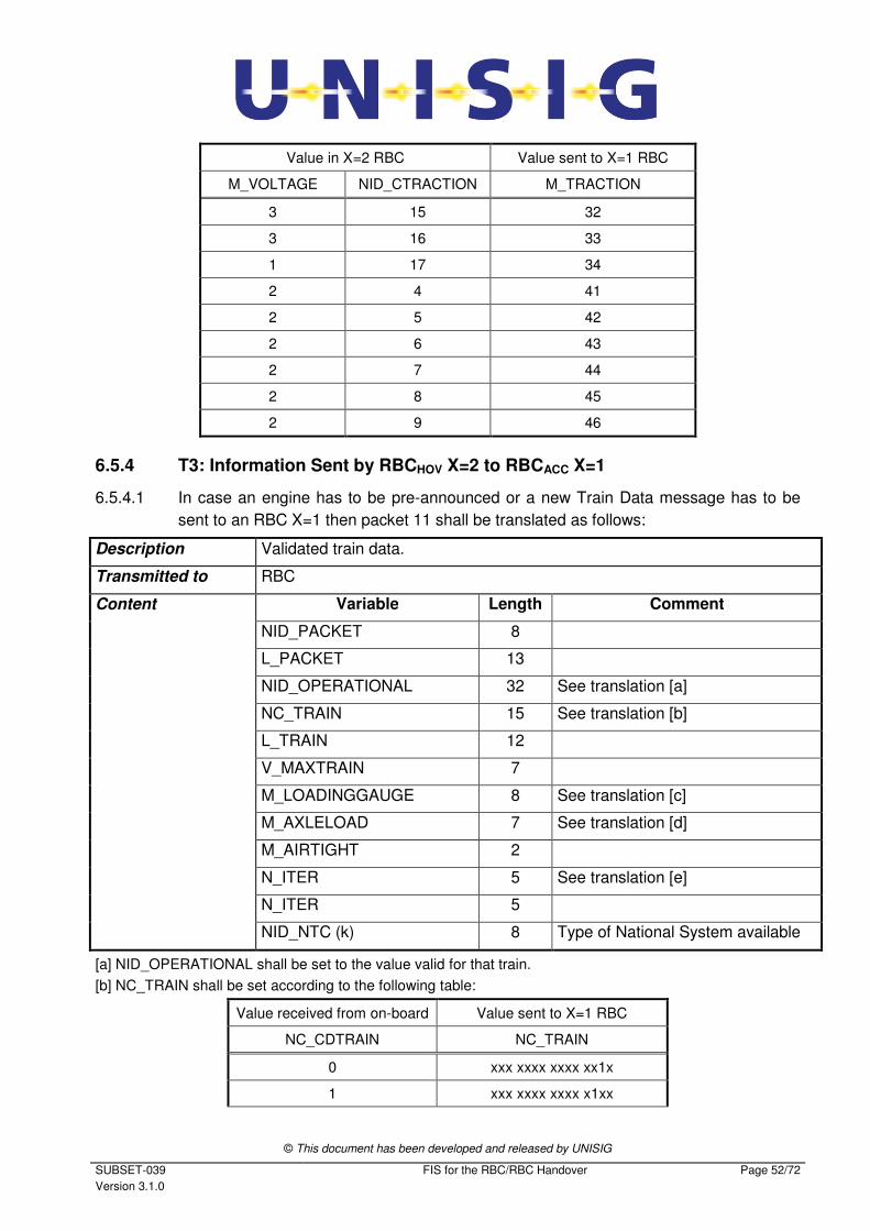
© This document has been developed and released by UNISIG
SUBSET-039
Version 3.1.0
FIS for the RBC/RBC Handover Page 52/72
Value in X=2 RBC Value sent to X=1 RBC
M_VOLTAGE NID_CTRACTION M_TRACTION
3 15 32
3 16 33
1 17 34
2 4 41
2 5 42
2 6 43
2 7 44
2 8 45
2 9 46
6.5.4 T3: Information Sent by RBCHOV X=2 to RBCACC X=1
6.5.4.1 In case an engine has to be pre-announced or a new Train Data message has to be
sent to an RBC X=1 then packet 11 shall be translated as follows:
Description Validated train data.
Transmitted to RBC
Content Variable Length Comment
NID_PACKET 8
L_PACKET 13
NID_OPERATIONAL 32 See translation [a]
NC_TRAIN 15 See translation [b]
L_TRAIN 12
V_MAXTRAIN 7
M_LOADINGGAUGE 8 See translation [c]
M_AXLELOAD 7 See translation [d]
M_AIRTIGHT 2
N_ITER 5 See translation [e]
N_ITER 5
NID_NTC (k) 8 Type of National System available
[a] NID_OPERATIONAL shall be set to the value valid for that train.
[b] NC_TRAIN shall be set according to the following table:
Value received from on-board Value sent to X=1 RBC
NC_CDTRAIN NC_TRAIN
0 xxx xxxx xxxx xx1x
1 xxx xxxx xxxx x1xx
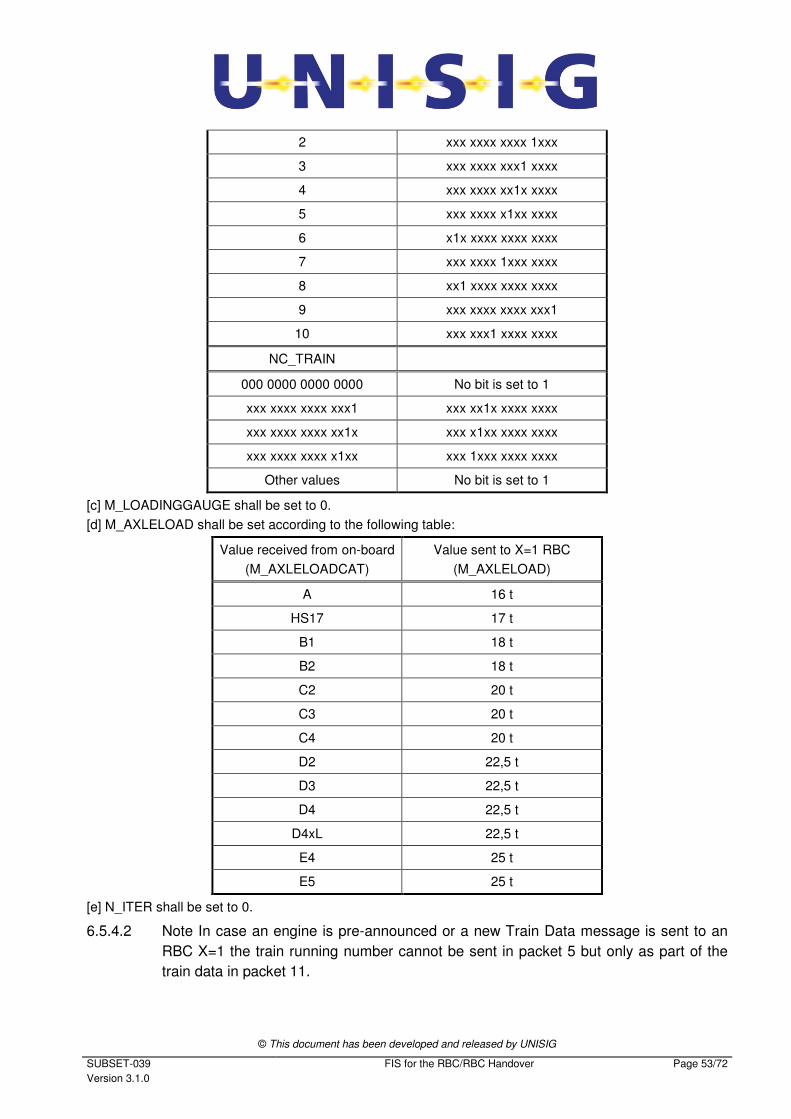
© This document has been developed and released by UNISIG
SUBSET-039
Version 3.1.0
FIS for the RBC/RBC Handover Page 53/72
2 xxx xxxx xxxx 1xxx
3 xxx xxxx xxx1 xxxx
4 xxx xxxx xx1x xxxx
5 xxx xxxx x1xx xxxx
6 x1x xxxx xxxx xxxx
7 xxx xxxx 1xxx xxxx
8 xx1 xxxx xxxx xxxx
9 xxx xxxx xxxx xxx1
10 xxx xxx1 xxxx xxxx
NC_TRAIN
000 0000 0000 0000 No bit is set to 1
xxx xxxx xxxx xxx1 xxx xx1x xxxx xxxx
xxx xxxx xxxx xx1x xxx x1xx xxxx xxxx
xxx xxxx xxxx x1xx xxx 1xxx xxxx xxxx
Other values No bit is set to 1
[c] M_LOADINGGAUGE shall be set to 0.
[d] M_AXLELOAD shall be set according to the following table:
Value received from on-board
(M_AXLELOADCAT)
Value sent to X=1 RBC
(M_AXLELOAD)
A 16 t
HS17 17 t
B1 18 t
B2 18 t
C2 20 t
C3 20 t
C4 20 t
D2 22,5 t
D3 22,5 t
D4 22,5 t
D4xL 22,5 t
E4 25 t
E5 25 t
[e] N_ITER shall be set to 0.
6.5.4.2 Note In case an engine is pre-announced or a new Train Data message is sent to an
RBC X=1 the train running number cannot be sent in packet 5 but only as part of the
train data in packet 11.
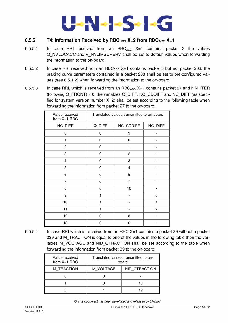
© This document has been developed and released by UNISIG
SUBSET-039
Version 3.1.0
FIS for the RBC/RBC Handover Page 54/72
6.5.5 T4: Information Received by RBCHOV X=2 from RBCACC X=1
6.5.5.1 In case RRI received from an RBCACC X=1 contains packet 3 the values
Q_NVLOCACC and V_NVLIMSUPERV shall be set to default values when forwarding
the information to the on-board.
6.5.5.2 In case RRI received from an RBCACC X=1 contains packet 3 but not packet 203, the
braking curve parameters contained in a packet 203 shall be set to pre-configured val-
ues (see 6.5.1.2) when forwarding the information to the on-board.
6.5.5.3 In case RRI, which is received from an RBCACC X=1 contains packet 27 and if N_ITER
(following Q_FRONT) ≠ 0, the variables Q_DIFF, NC_CDDIFF and NC_DIFF (as speci-
fied for system version number X=2) shall be set according to the following table when
forwarding the information from packet 27 to the on-board:
Value received from X=1 RBC
Translated values transmitted to on-board
NC_DIFF Q_DIFF NC_CDDIFF NC_DIFF
0 0 9 -
1 0 0 -
2 0 1 -
3 0 2 -
4 0 3 -
5 0 4 -
6 0 5 -
7 0 7 -
8 0 10 -
9 1 - 0
10 1 - 1
11 1 - 2
12 0 8 -
13 0 6 -
6.5.5.4 In case RRI which is received from an RBC X=1 contains a packet 39 without a packet
239 and M_TRACTION is equal to one of the values in the following table then the var-
iables M_VOLTAGE and NID_CTRACTION shall be set according to the table when
forwarding the information from packet 39 to the on-board:
Value received from X=1 RBC
Translated values transmitted to on-board
M_TRACTION M_VOLTAGE NID_CTRACTION
0 0 -
1 3 10
2 1 12
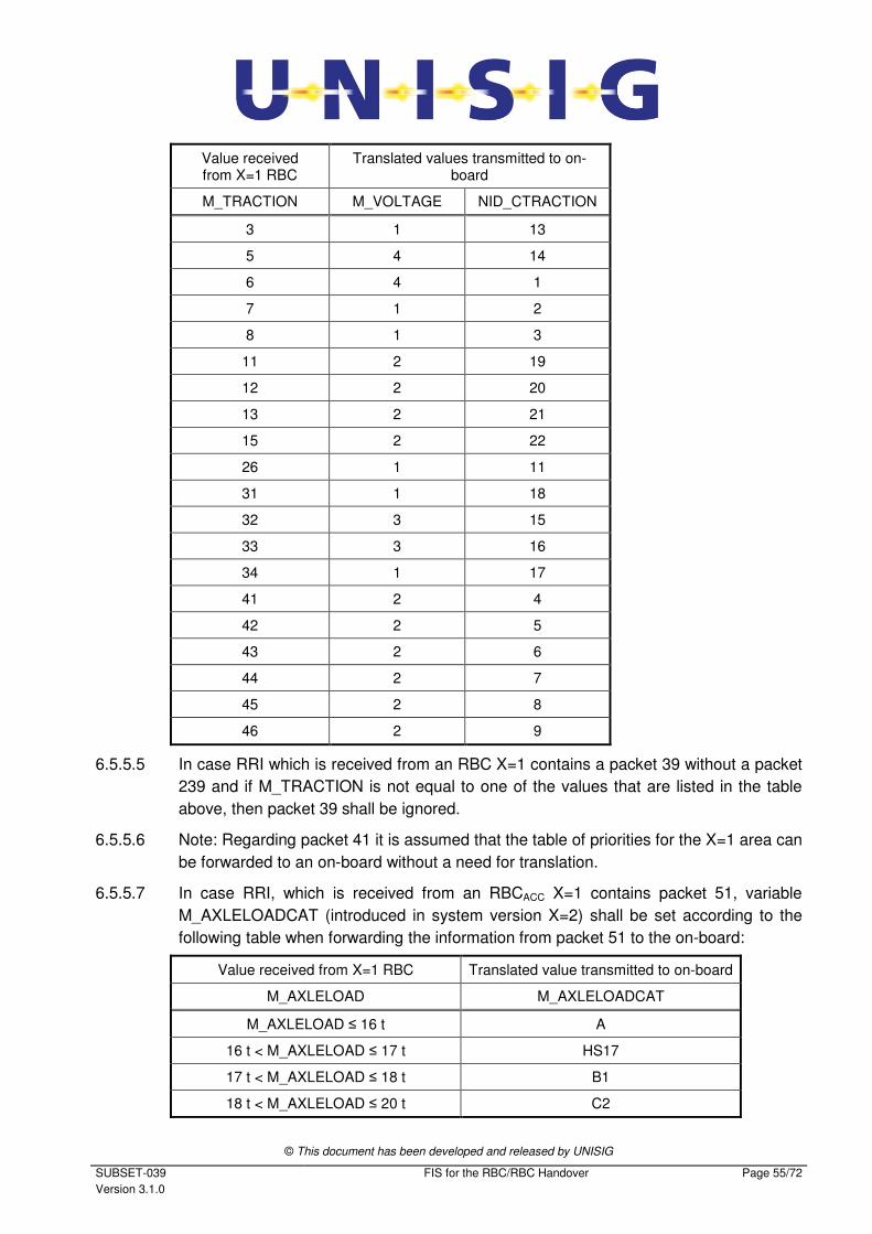
© This document has been developed and released by UNISIG
SUBSET-039
Version 3.1.0
FIS for the RBC/RBC Handover Page 55/72
Value received from X=1 RBC
Translated values transmitted to on-board
M_TRACTION M_VOLTAGE NID_CTRACTION
3 1 13
5 4 14
6 4 1
7 1 2
8 1 3
11 2 19
12 2 20
13 2 21
15 2 22
26 1 11
31 1 18
32 3 15
33 3 16
34 1 17
41 2 4
42 2 5
43 2 6
44 2 7
45 2 8
46 2 9
6.5.5.5 In case RRI which is received from an RBC X=1 contains a packet 39 without a packet
239 and if M_TRACTION is not equal to one of the values that are listed in the table
above, then packet 39 shall be ignored.
6.5.5.6 Note: Regarding packet 41 it is assumed that the table of priorities for the X=1 area can
be forwarded to an on-board without a need for translation.
6.5.5.7 In case RRI, which is received from an RBCACC X=1 contains packet 51, variable
M_AXLELOADCAT (introduced in system version X=2) shall be set according to the
following table when forwarding the information from packet 51 to the on-board:
Value received from X=1 RBC Translated value transmitted to on-board
M_AXLELOAD M_AXLELOADCAT
M_AXLELOAD ≤ 16 t A
16 t < M_AXLELOAD ≤ 17 t HS17
17 t < M_AXLELOAD ≤ 18 t B1
18 t < M_AXLELOAD ≤ 20 t C2
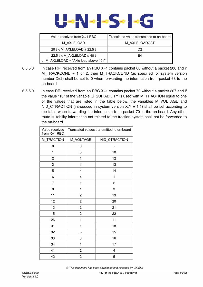
© This document has been developed and released by UNISIG
SUBSET-039
Version 3.1.0
FIS for the RBC/RBC Handover Page 56/72
Value received from X=1 RBC Translated value transmitted to on-board
M_AXLELOAD M_AXLELOADCAT
20 t < M_AXLELOAD ≤ 22.5 t D2
22.5 t < M_AXLELOAD ≤ 40 t
or M_AXLELOAD = “Axle load above 40 t”
E4
6.5.5.8 In case RRI received from an RBC X=1 contains packet 68 without a packet 206 and if
M_TRACKCOND = 1 or 2, then M_TRACKCOND (as specified for system version
number X=2) shall be set to 0 when forwarding the information from packet 68 to the
on-board.
6.5.5.9 In case RRI received from an RBC X=1 contains packet 70 without a packet 207 and if
the value “10” of the variable Q_SUITABILITY is used with M_TRACTION equal to one
of the values that are listed in the table below, the variables M_VOLTAGE and
NID_CTRACTION (introduced in system version X.Y = 1.1) shall be set according to
the table when forwarding the information from packet 70 to the on-board. Any other
route suitability information not related to the traction system shall not be forwarded to
the on-board.
Value received from X=1 RBC
Translated values transmitted to on-board
M_TRACTION M_VOLTAGE NID_CTRACTION
0 0 -
1 3 10
2 1 12
3 1 13
5 4 14
6 4 1
7 1 2
8 1 3
11 2 19
12 2 20
13 2 21
15 2 22
26 1 11
31 1 18
32 3 15
33 3 16
34 1 17
41 2 4
42 2 5
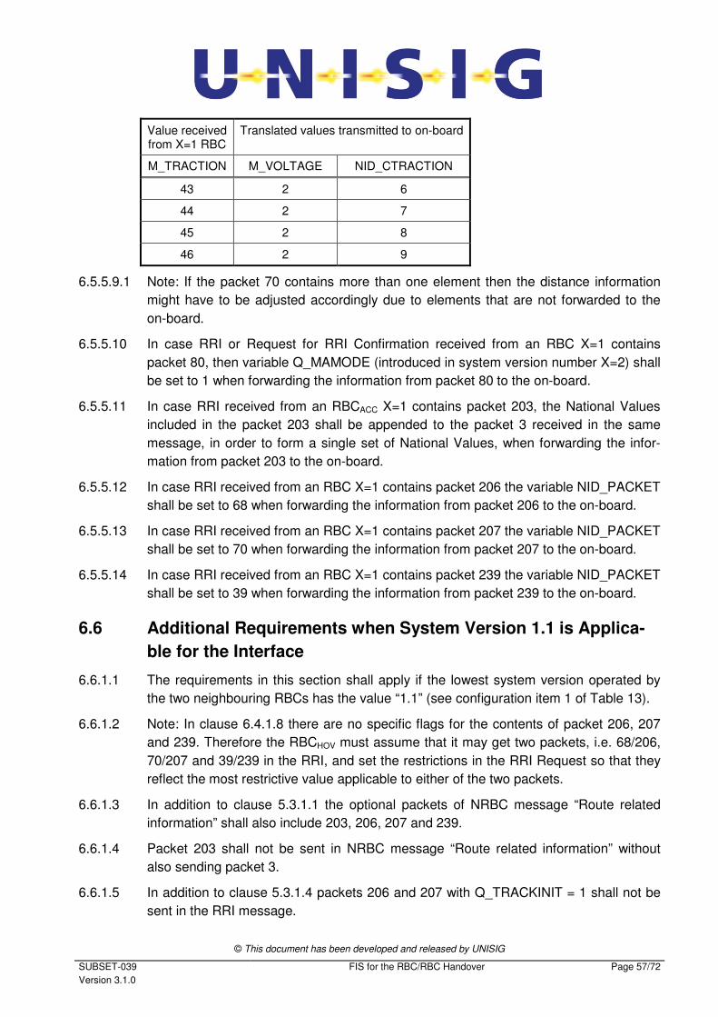
© This document has been developed and released by UNISIG
SUBSET-039
Version 3.1.0
FIS for the RBC/RBC Handover Page 57/72
Value received from X=1 RBC
Translated values transmitted to on-board
M_TRACTION M_VOLTAGE NID_CTRACTION
43 2 6
44 2 7
45 2 8
46 2 9
6.5.5.9.1 Note: If the packet 70 contains more than one element then the distance information
might have to be adjusted accordingly due to elements that are not forwarded to the
on-board.
6.5.5.10 In case RRI or Request for RRI Confirmation received from an RBC X=1 contains
packet 80, then variable Q_MAMODE (introduced in system version number X=2) shall
be set to 1 when forwarding the information from packet 80 to the on-board.
6.5.5.11 In case RRI received from an RBCACC X=1 contains packet 203, the National Values
included in the packet 203 shall be appended to the packet 3 received in the same
message, in order to form a single set of National Values, when forwarding the infor-
mation from packet 203 to the on-board.
6.5.5.12 In case RRI received from an RBC X=1 contains packet 206 the variable NID_PACKET
shall be set to 68 when forwarding the information from packet 206 to the on-board.
6.5.5.13 In case RRI received from an RBC X=1 contains packet 207 the variable NID_PACKET
shall be set to 70 when forwarding the information from packet 207 to the on-board.
6.5.5.14 In case RRI received from an RBC X=1 contains packet 239 the variable NID_PACKET
shall be set to 39 when forwarding the information from packet 239 to the on-board.
6.6 Additional Requirements when System Version 1.1 is Applica-
ble for the Interface
6.6.1.1 The requirements in this section shall apply if the lowest system version operated by
the two neighbouring RBCs has the value “1.1” (see configuration item 1 of Table 13).
6.6.1.2 Note: In clause 6.4.1.8 there are no specific flags for the contents of packet 206, 207
and 239. Therefore the RBCHOV must assume that it may get two packets, i.e. 68/206,
70/207 and 39/239 in the RRI, and set the restrictions in the RRI Request so that they
reflect the most restrictive value applicable to either of the two packets.
6.6.1.3 In addition to clause 5.3.1.1 the optional packets of NRBC message “Route related
information” shall also include 203, 206, 207 and 239.
6.6.1.4 Packet 203 shall not be sent in NRBC message “Route related information” without
also sending packet 3.
6.6.1.5 In addition to clause 5.3.1.4 packets 206 and 207 with Q_TRACKINIT = 1 shall not be
sent in the RRI message.
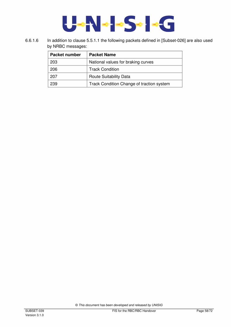
© This document has been developed and released by UNISIG
SUBSET-039
Version 3.1.0
FIS for the RBC/RBC Handover Page 58/72
6.6.1.6 In addition to clause 5.5.1.1 the following packets defined in [Subset-026] are also used
by NRBC messages:
Packet number Packet Name
203 National values for braking curves
206 Track Condition
207 Route Suitability Data
239 Track Condition Change of traction system
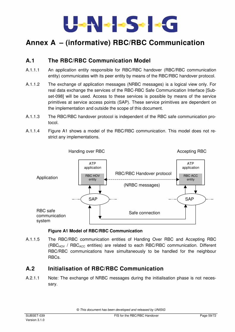
© This document has been developed and released by UNISIG
SUBSET-039
Version 3.1.0
FIS for the RBC/RBC Handover Page 59/72
Annex A – (informative) RBC/RBC Communication
A.1 The RBC/RBC Communication Model
A.1.1.1 An application entity responsible for RBC/RBC handover (RBC/RBC communication
entity) communicates with its peer entity by means of the RBC/RBC handover protocol.
A.1.1.2 The exchange of application messages (NRBC messages) is a logical view only. For
real data exchange the services of the RBC-RBC Safe Communication Interface [Sub-
set-098] will be used. Access to these services is possible by means of the service
primitives at service access points (SAP). These service primitives are dependent on
the implementation and outside the scope of this document.
A.1.1.3 The RBC/RBC handover protocol is independent of the RBC safe communication pro-
tocol.
A.1.1.4 Figure A1 shows a model of the RBC/RBC communication. This model does not re-
strict any implementations.
Safe connection
Application RBC/RBC Handover protocol
Accepting RBC
SAP SAP
Handing over RBC
RBC safe communication system
ATP application
RBC ACC entity
ATP application
RBC HOV entity
(NRBC messages)
Figure A1 Model of RBC/RBC Communication
A.1.1.5 The RBC/RBC communication entities of Handing Over RBC and Accepting RBC
(RBCHOV / RBCACC entities) are related to each RBC/RBC communication. Different
RBC/RBC communications have simultaneously to be handled for the neighbour
RBCs.
A.2 Initialisation of RBC/RBC Communication
A.2.1.1 Note: The exchange of NRBC messages during the initialisation phase is not neces-
sary.
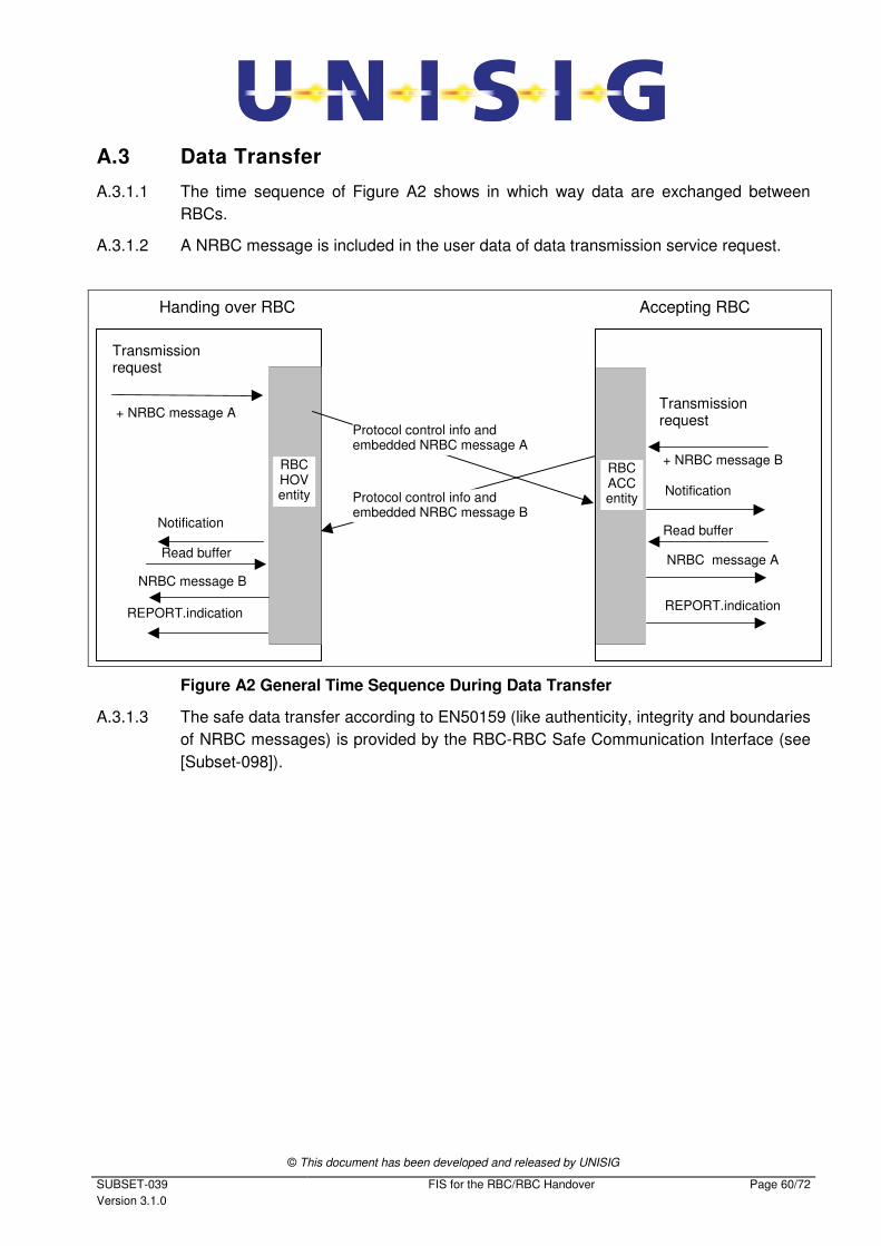
© This document has been developed and released by UNISIG
SUBSET-039
Version 3.1.0
FIS for the RBC/RBC Handover Page 60/72
A.3 Data Transfer
A.3.1.1 The time sequence of Figure A2 shows in which way data are exchanged between
RBCs.
A.3.1.2 A NRBC message is included in the user data of data transmission service request.
Transmissionrequest
Handing over RBC
Notification
REPORT.indication
Protocol control info andembedded NRBC message A
Protocol control info andembedded NRBC message B
Transmissionrequest
Notification
+ NRBC message A
+ NRBC message B
NRBC message A
NRBC message B
Read buffer
Read buffer
Accepting RBC
RBCHOVentity
RBCACCentity
REPORT.indication
Figure A2 General Time Sequence During Data Transfer
A.3.1.3 The safe data transfer according to EN50159 (like authenticity, integrity and boundaries
of NRBC messages) is provided by the RBC-RBC Safe Communication Interface (see
[Subset-098]).
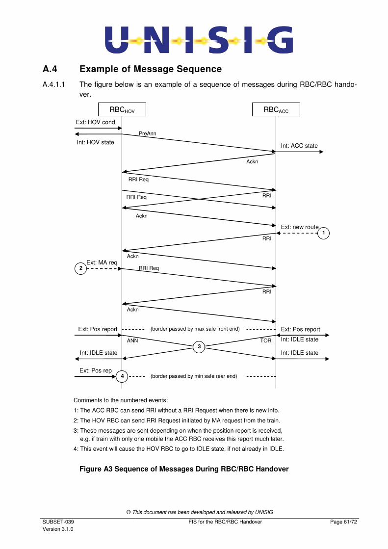
© This document has been developed and released by UNISIG
SUBSET-039
Version 3.1.0
FIS for the RBC/RBC Handover Page 61/72
A.4 Example of Message Sequence
A.4.1.1 The figure below is an example of a sequence of messages during RBC/RBC hando-
ver.
RBCHOV RBCACC
Ext: HOV cond
Int: HOV state
PreAnn
RRI Req
RRI
Int: ACC state
Ext: new route
RRI
Ackn
Ackn
RRI Req
RRI
Ackn
Ext: Pos report Ext: Pos report
Int: IDLE state
Int: IDLE state
TOR ANN
Ext: MA req
(border passed by max safe front end)
Int: IDLE state
Comments to the numbered events:
1: The ACC RBC can send RRI without a RRI Request when there is new info.
2: The HOV RBC can send RRI Request initiated by MA request from the train.
3: These messages are sent depending on when the position report is received,
e.g. if train with only one mobile the ACC RBC receives this report much later.
4: This event will cause the HOV RBC to go to IDLE state, if not already in IDLE.
(border passed by min safe rear end)
1
2
3
4 Ext: Pos rep
Ackn
RRI Req
Figure A3 Sequence of Messages During RBC/RBC Handover

© This document has been developed and released by UNISIG
SUBSET-039
Version 3.1.0
FIS for the RBC/RBC Handover Page 62/72
A.5 Example of Life Sign
A.5.1.1 The following figure shows an example of timers for communication supervision in case
of one ongoing handover transaction. The first sending of a Life Sign message after es-
tablishment of the safe connection is not shown.
Start
Expired
Expired
Start
Expired
Start
Expired
Start
Expired
Expired
Expired
Restart
Restart
Restart
Restart
Restart
Restart
Restart
Restart
Restart
Restart
Restart
Restart
Restart
Restart
Restart
Restart
Restart
Restart
Restart
Restart
Restart
Restart
Restart
Restart
Start
Start
Start
EXT: HOV condition
EXT: Position report
EXT: New route
EXT: Border passed
Life Sign
Pre-Announcement
Announcement
RRI Request
RRI
Ack
TOR
Life Sign
Ack
Life Sign
Life Sign
RRI
Ack
Life Sign
Life Sign
Life Sign
Life Sign
Receive Timer Transmit Timer Transmit Timer
Receive Timer
RBC1 RBC2
Start
Expired
Restart
Figure A4 Life Sign
© This document has been developed and released by UNISIG
SUBSET-039
Version 3.1.0
FIS for the RBC/RBC Handover Page 63/72
A.6 Error Handling
A.6.1.1 The lower protocol layers of the RBC/RBC communication can provide implementation
specific local error reports to the RBC application.
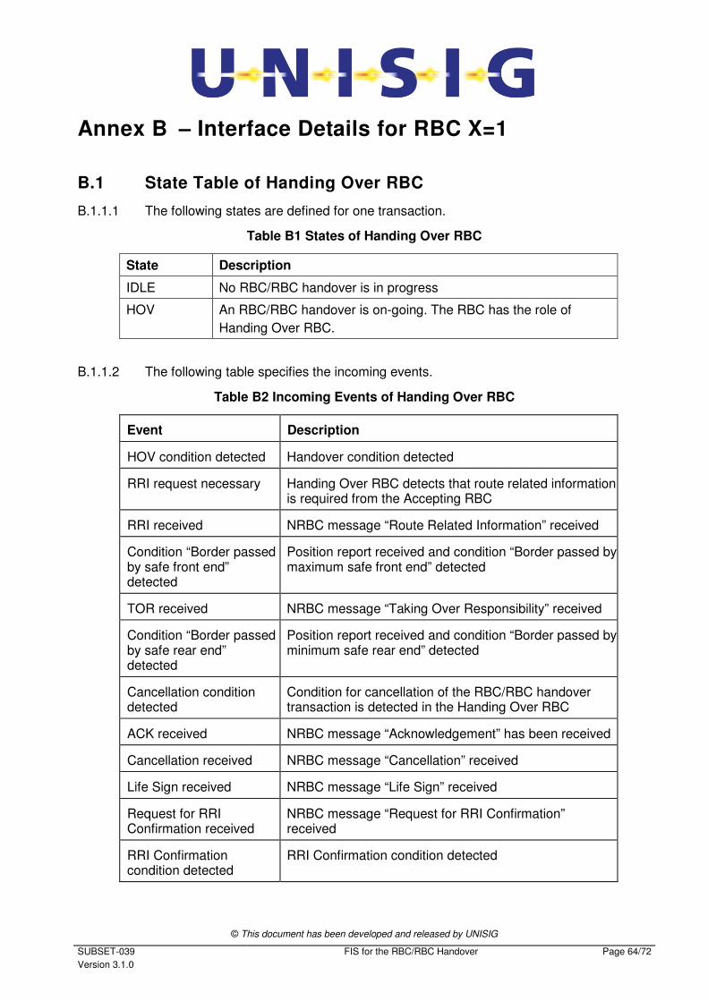
© This document has been developed and released by UNISIG
SUBSET-039
Version 3.1.0
FIS for the RBC/RBC Handover Page 64/72
Annex B – Interface Details for RBC X=1
B.1 State Table of Handing Over RBC
B.1.1.1 The following states are defined for one transaction.
Table B1 States of Handing Over RBC
State Description
IDLE No RBC/RBC handover is in progress
HOV An RBC/RBC handover is on-going. The RBC has the role of
Handing Over RBC.
B.1.1.2 The following table specifies the incoming events.
Table B2 Incoming Events of Handing Over RBC
Event Description
HOV condition detected Handover condition detected
RRI request necessary Handing Over RBC detects that route related information is required from the Accepting RBC
RRI received NRBC message “Route Related Information” received
Condition “Border passed by safe front end” detected
Position report received and condition “Border passed by maximum safe front end” detected
TOR received NRBC message “Taking Over Responsibility” received
Condition “Border passed by safe rear end” detected
Position report received and condition “Border passed by minimum safe rear end” detected
Cancellation condition detected
Condition for cancellation of the RBC/RBC handover transaction is detected in the Handing Over RBC
ACK received NRBC message “Acknowledgement” has been received
Cancellation received NRBC message “Cancellation” received
Life Sign received NRBC message “Life Sign” received
Request for RRI Confirmation received
NRBC message “Request for RRI Confirmation” received
RRI Confirmation condition detected
RRI Confirmation condition detected
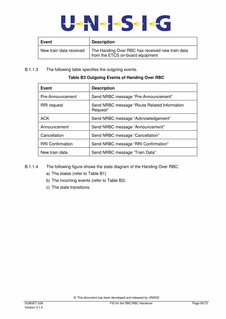
© This document has been developed and released by UNISIG
SUBSET-039
Version 3.1.0
FIS for the RBC/RBC Handover Page 65/72
Event Description
New train data received The Handing Over RBC has received new train data from the ETCS on-board equipment
B.1.1.3 The following table specifies the outgoing events.
Table B3 Outgoing Events of Handing Over RBC
Event Description
Pre-Announcement Send NRBC message “Pre-Announcement”
RRI request Send NRBC message “Route Related Information Request”
ACK Send NRBC message “Acknowledgement”
Announcement Send NRBC message “Announcement”
Cancellation Send NRBC message “Cancellation”
RRI Confirmation Send NRBC message “RRI Confirmation”
New train data Send NRBC message “Train Data”
B.1.1.4 The following figure shows the state diagram of the Handing Over RBC:
a) The states (refer to Table B1)
b) The incoming events (refer to Table B2)
c) The state transitions.
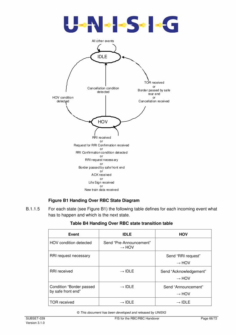
© This document has been developed and released by UNISIG
SUBSET-039
Version 3.1.0
FIS for the RBC/RBC Handover Page 66/72
IDLE
HOV
Cancellation conditiondetected
HOV condition detected
TOR received
or Border passed by safe
rear end or
Cancellat ion received
RRI received or
Request for RRI Confirmation receivedor
RRI Conf irmation condit ion detected or
RRI request necessary
or Border passed by safe f ront end
or ACK received
or Life Sign received
or New train data received
All other events
Figure B1 Handing Over RBC State Diagram
B.1.1.5 For each state (see Figure B1) the following table defines for each incoming event what
has to happen and which is the next state.
Table B4 Handing Over RBC state transition table
Event IDLE HOV
HOV condition detected Send “Pre-Announcement” → HOV
RRI request necessary Send “RRI request”
→ HOV
RRI received → IDLE Send “Acknowledgement”
→ HOV
Condition “Border passed by safe front end”
→ IDLE Send “Announcement”
→ HOV
TOR received → IDLE → IDLE
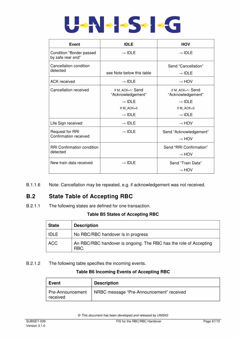
© This document has been developed and released by UNISIG
SUBSET-039
Version 3.1.0
FIS for the RBC/RBC Handover Page 67/72
Event IDLE HOV
Condition “Border passed by safe rear end”
→ IDLE → IDLE
Cancellation condition detected
see Note below this table
Send “Cancellation”
→ IDLE
ACK received → IDLE → HOV
Cancellation received If M_ACK=1: Send “Acknowledgement”
→ IDLE
If M_ACK=0
→ IDLE
If M_ACK=1: Send “Acknowledgement”
→ IDLE
If M_ACK=0
→ IDLE
Life Sign received → IDLE → HOV
Request for RRI Confirmation received
→ IDLE Send “Acknowledgement”
→ HOV
RRI Confirmation condition detected
Send “RRI Confirmation”
→ HOV
New train data received → IDLE Send “Train Data”
→ HOV
B.1.1.6 Note: Cancellation may be repeated, e.g. if acknowledgement was not received.
B.2 State Table of Accepting RBC
B.2.1.1 The following states are defined for one transaction.
Table B5 States of Accepting RBC
State Description
IDLE No RBC/RBC handover is in progress
ACC An RBC/RBC handover is ongoing. The RBC has the role of Accepting RBC.
B.2.1.2 The following table specifies the incoming events.
Table B6 Incoming Events of Accepting RBC
Event Description
Pre-Announcement received
NRBC message “Pre-Announcement” received
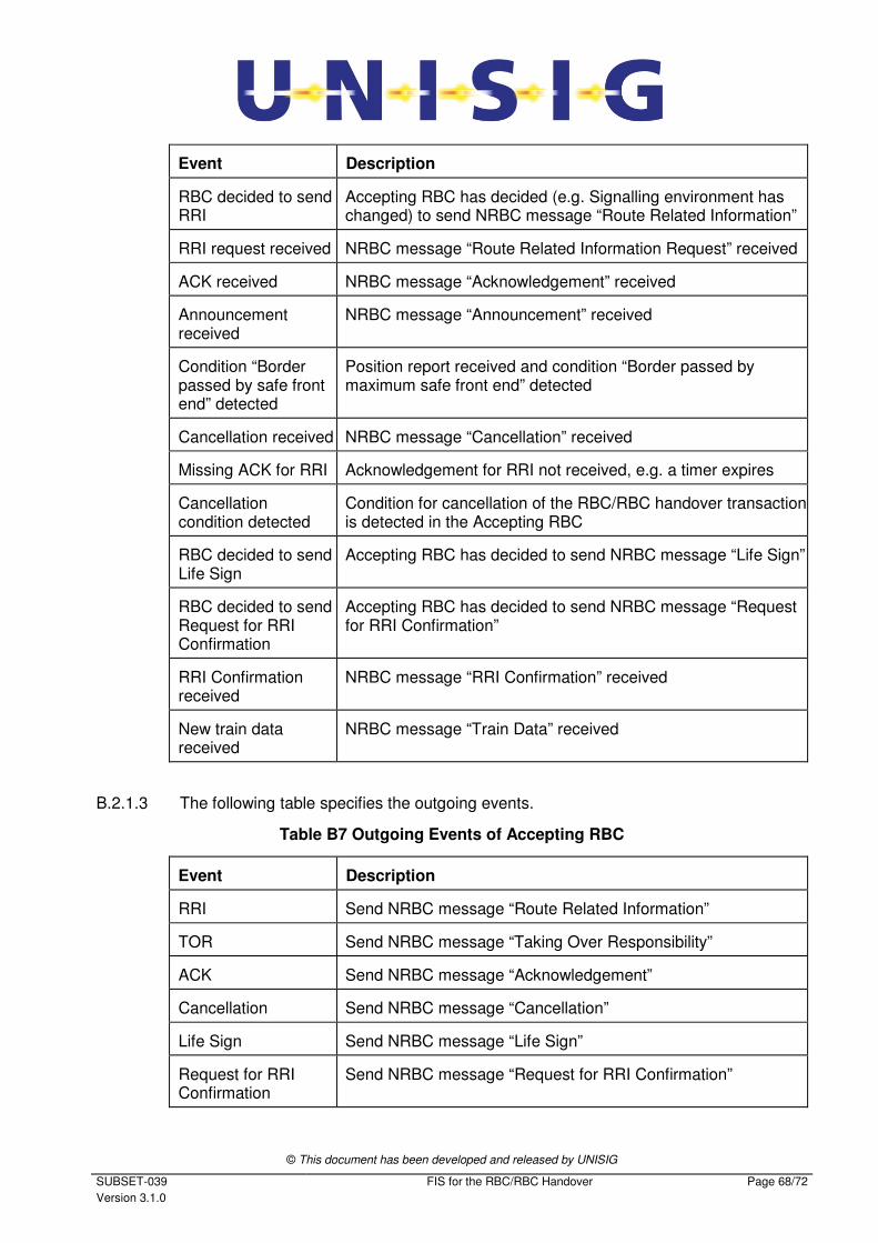
© This document has been developed and released by UNISIG
SUBSET-039
Version 3.1.0
FIS for the RBC/RBC Handover Page 68/72
Event Description
RBC decided to send RRI
Accepting RBC has decided (e.g. Signalling environment has changed) to send NRBC message “Route Related Information”
RRI request received NRBC message “Route Related Information Request” received
ACK received NRBC message “Acknowledgement” received
Announcement received
NRBC message “Announcement” received
Condition “Border passed by safe front end” detected
Position report received and condition “Border passed by maximum safe front end” detected
Cancellation received NRBC message “Cancellation” received
Missing ACK for RRI Acknowledgement for RRI not received, e.g. a timer expires
Cancellation condition detected
Condition for cancellation of the RBC/RBC handover transaction is detected in the Accepting RBC
RBC decided to send Life Sign
Accepting RBC has decided to send NRBC message “Life Sign”
RBC decided to send Request for RRI Confirmation
Accepting RBC has decided to send NRBC message “Request for RRI Confirmation”
RRI Confirmation received
NRBC message “RRI Confirmation” received
New train data received
NRBC message “Train Data” received
B.2.1.3 The following table specifies the outgoing events.
Table B7 Outgoing Events of Accepting RBC
Event Description
RRI Send NRBC message “Route Related Information”
TOR Send NRBC message “Taking Over Responsibility”
ACK Send NRBC message “Acknowledgement”
Cancellation Send NRBC message “Cancellation”
Life Sign Send NRBC message “Life Sign”
Request for RRI Confirmation
Send NRBC message “Request for RRI Confirmation”
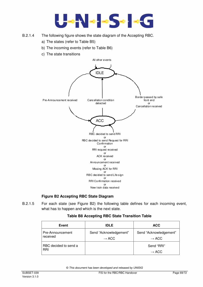
© This document has been developed and released by UNISIG
SUBSET-039
Version 3.1.0
FIS for the RBC/RBC Handover Page 69/72
B.2.1.4 The following figure shows the state diagram of the Accepting RBC.
a) The states (refer to Table B5)
b) The incoming events (refer to Table B6)
c) The state transitions
IDLE
ACC
RBC decided to send RRI
or RBC decided to send Request for RRI
Confirmation or
RRI request received
or ACK received
or Announcement received
or
Missing ACK for RRI or
RBC dec ided to send Life s ign or
RRI Confirmation received
or New train data received
All other events
Cancellation condit iondetected
Pre-Announcement received Border passed by safe
front end or
Cancellat ion received
Figure B2 Accepting RBC State Diagram
B.2.1.5 For each state (see Figure B2) the following table defines for each incoming event,
what has to happen and which is the next state.
Table B8 Accepting RBC State Transition Table
Event IDLE ACC
Pre-Announcement received
Send “Acknowledgement”
→ ACC
Send “Acknowledgement”
→ ACC
RBC decided to send a RRI
Send “RRI”
→ ACC
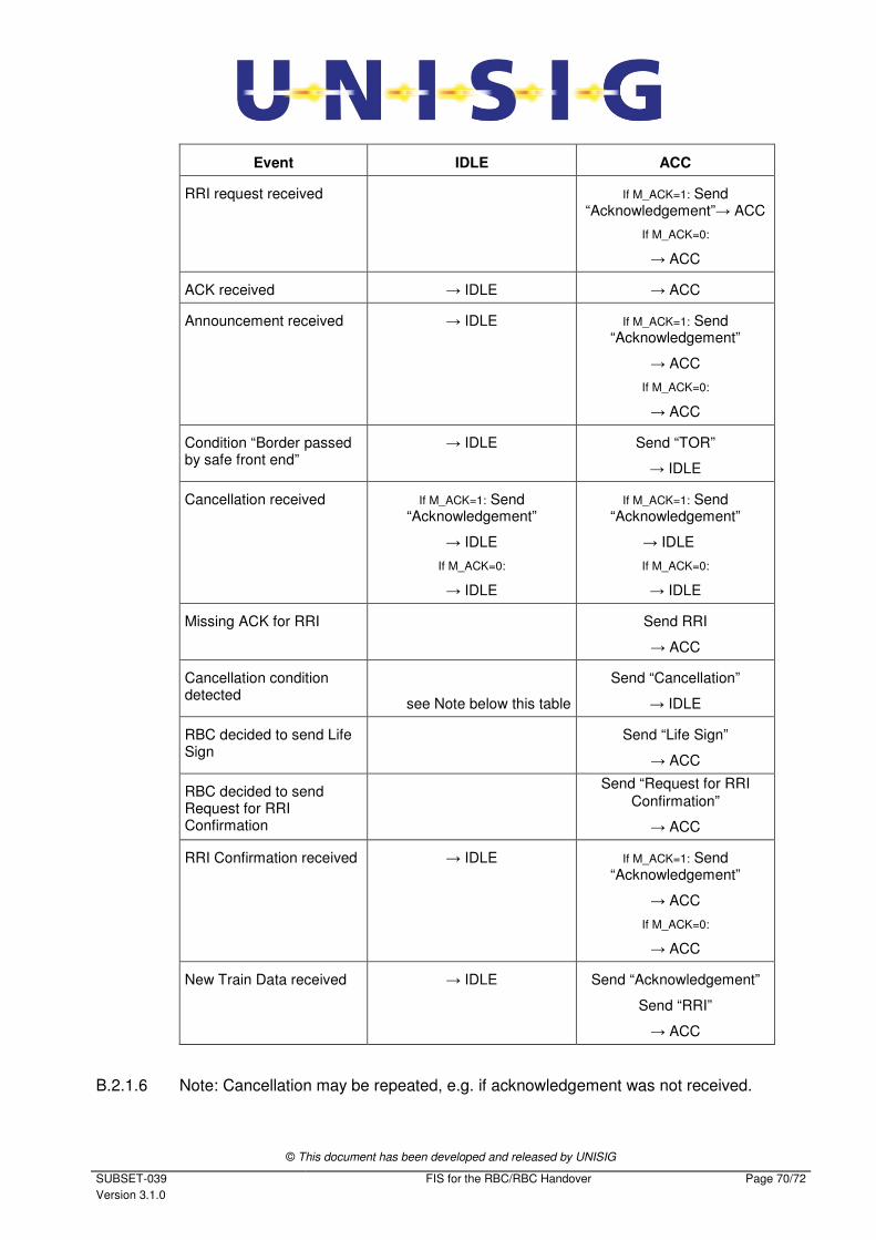
© This document has been developed and released by UNISIG
SUBSET-039
Version 3.1.0
FIS for the RBC/RBC Handover Page 70/72
Event IDLE ACC
RRI request received If M_ACK=1: Send “Acknowledgement”→ ACC
If M_ACK=0:
→ ACC
ACK received → IDLE → ACC
Announcement received → IDLE If M_ACK=1: Send “Acknowledgement”
→ ACC
If M_ACK=0:
→ ACC
Condition “Border passed by safe front end”
→ IDLE Send “TOR”
→ IDLE
Cancellation received If M_ACK=1: Send “Acknowledgement”
→ IDLE
If M_ACK=0:
→ IDLE
If M_ACK=1: Send “Acknowledgement”
→ IDLE
If M_ACK=0:
→ IDLE
Missing ACK for RRI Send RRI
→ ACC
Cancellation condition detected
see Note below this table
Send “Cancellation”
→ IDLE
RBC decided to send Life Sign
Send “Life Sign”
→ ACC
RBC decided to send Request for RRI Confirmation
Send “Request for RRI
Confirmation”
→ ACC
RRI Confirmation received → IDLE If M_ACK=1: Send “Acknowledgement”
→ ACC
If M_ACK=0:
→ ACC
New Train Data received → IDLE
Send “Acknowledgement”
Send “RRI”
→ ACC
B.2.1.6 Note: Cancellation may be repeated, e.g. if acknowledgement was not received.
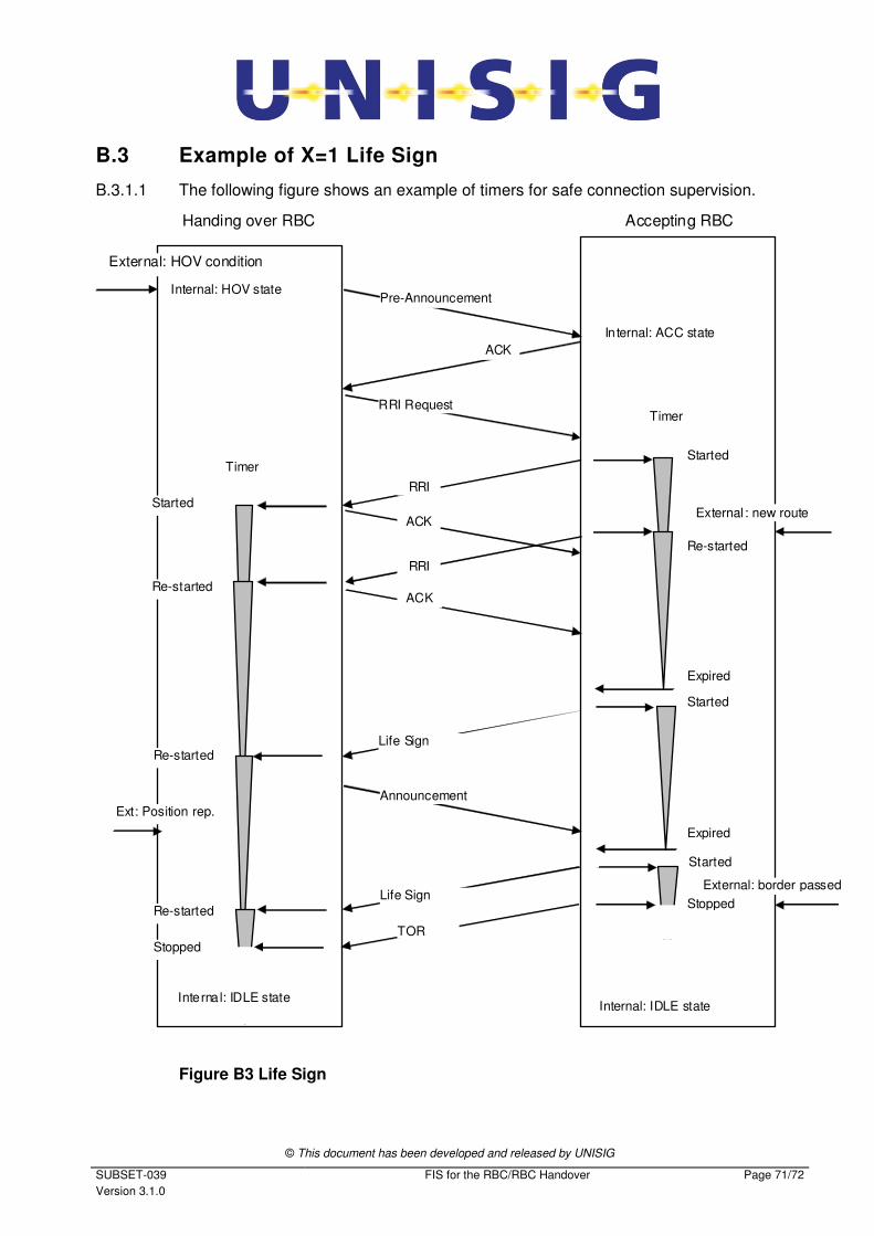
© This document has been developed and released by UNISIG
SUBSET-039
Version 3.1.0
FIS for the RBC/RBC Handover Page 71/72
B.3 Example of X=1 Life Sign
B.3.1.1 The following figure shows an example of timers for safe connection supervision.
External: HOV condition
Handing over RBC
Pre-Announcement Internal: HOV state
Started
Accepting RBC
RRI Request
External : new route
Re-started
Started
Re-started
Expired
Started
Started
Expired
Ext: Position rep.
RRI
Life Sign
Announcement
Life Sign
Re-started
In ternal: ACC state
Timer
RRI
ACK
ACK
Timer
Re-started
External: border passed
Stopped
TOR
Stopped
Internal: IDLE state
Internal: IDLE state
ACK
Figure B3 Life Sign
© This document has been developed and released by UNISIG
SUBSET-039
Version 3.1.0
FIS for the RBC/RBC Handover Page 72/72
B.3.1.2 Notes:
1. The message receiving timer of the Handing Over RBC will not be started until
receiving the first RRI: its task is supervision because of a possible restrictive
RRI. This could not be the first one.
2. The Life Sign transmitting timer will be started after sending an NRBC message
(RRI, ACK or Life Sign): supervision is only necessary during an ongoing transac-
tion.
Recommended


![FIS for the RBC/RBC Handover...4.2.1.1 The RBC/RBC communication shall be established according to the rules of the underlying RBC-RBC Safe Communication Interface [Subset-098]. Further](https://img.pdfslide.us/doc/110x75/5e331307d520b57b5677b3fa/fis-for-the-rbcrbc-handover-4211-the-rbcrbc-communication-shall-be-established.jpg)