Table Top Type Robot TTA First Step Guide Fifth Edition
Thank you for purchasing our product. Make sure to read the Safety Guide and detailed Operation Manual (DVD) included with the product in addition to this First Step Guide to ensure correct use. This Operation Manual is original.
• Using or copying all or part of this Operation Manual without permission is prohibited. • The company names, names of products and trademarks of each company shown in the sentences
are registered trademarks.
Product Check This product is comprised of the following parts if it is of standard configuration. If you find any fault in the contained model or any missing parts, contact us or our distributor.
1. Parts No. Part Name Model Quantity Reference
1 Controller Main Body (with a built-in controller)
Refer to “How to read the model plate”, “How to read the model No.” 1
Accessories
2 Power Supply Plug AP-400-C (Supplier : Yamate Electric Co., Ltd.) 1
3 I/O Flat Cable CB-DS-PIO020 1 4 First Step Guide 1 5 Instruction Manual (DVD) 1 6 Safety Guide 1
2. Optional Components No. Part Name Model 1 Main Body Mounting Bracket (with set bolts and nuts) TT-FT
3. Teaching Tool (Option) The personal computer application software or teaching pendant is required for the operations including program creation and setup such as position setting and parameter setting with teaching. Use either of them.
No. Part Name Model Reference
1 PC Software (with RS232C cable + Emergency stop box) IA-101-X-MW RS232C→RS232C*1
2 PC Software (USB conversion adapter + RS232C cable + Cable and emergency stop box)
IA-101-X-USBMW USB→RS232C*1
3 PC Software (with USB Cable + Dummy plug) IA-101-TTA-USB USB→USB*1 4 Touch panel teaching TB-01 – 5 Touch panel teaching (with deadman switch) TB-01D, TB01DR – 6 Teaching pendant SEL-T – 7 Teaching pendant (with deadman switch) SEL-TD –
*1 The communication port on the left is for the personal computer and on the right is for the TTA.
4. Instruction Manuals related to this product, which are contained in the DVD. No. Name Manual No. 1 Table Top Type Robot TT Instruction Manual ME0320 2 PC software IA-101-X-MW Instruction Manual ME0154 3 Touch panel teaching TB-01, TB-01D, TB-01DR Instruction Manual ME0325 4 Teaching pendant SEL-T/TD Instruction Manual*1 ME0183 5 DeviceNet Instruction Manual ME0124 6 CC-Link Instruction Manual ME0123 7 PROFIBUS-DP Instruction Manual ME0153 8 EtherNet/IP Instruction Manual ME0308 9 EtherCAT Instruction Manual ME0309
*1 Applicable in Ver.1.16 and later with hardware revision “2”
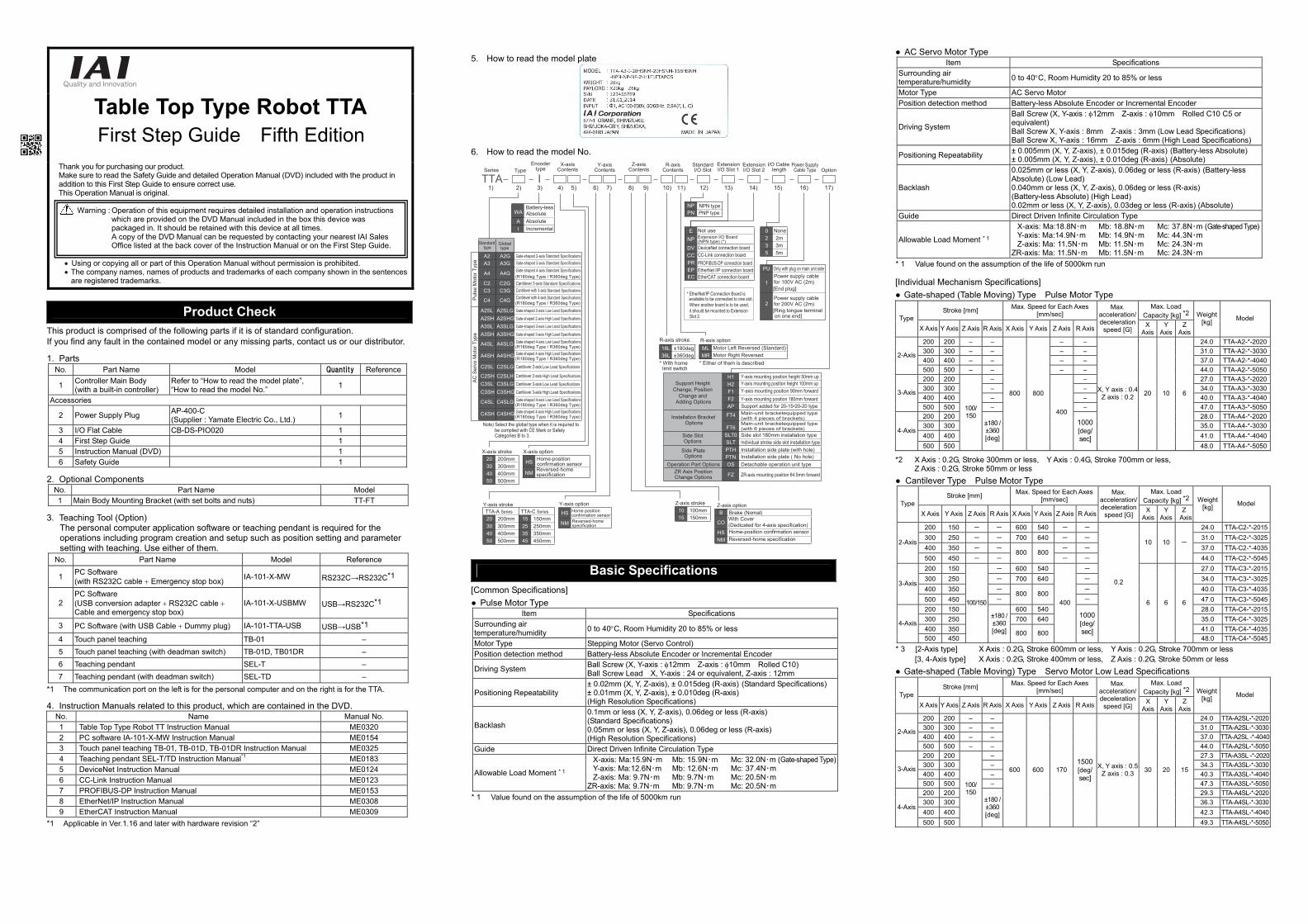
5. How to read the model plate
6. How to read the model No.
TTA1) 2) 3) 4) 5) 6) 7) 8) 9) 10) 11) 12) 13) 14) 15) 16) 17)
I
* EtherNet/IP Connection Board is available to be connected to one slot.When another board is to be used, it should be mounted to Extension Slot 2.
WABattery-less Absolute
A AbsoluteI Incremental
20 200mm30 300mm40 400mm50 500mm
TTA-A Series TTA-C Series20 200mm 15 150mm30 300mm 25 250mm40 400mm 35 350mm50 500mm 45 450mm
HS
NM
HS
NM
NPPN
PU
1[End plug]
2[Ring tongue terminal on one end]
02 2m3 3m5 5m
ENPDVCCPREP
10 100mm15 150mm
18L ±180deg36L ±360deg
* With home limit switch
B Brake (Nomal)
COWith Cover (Dedicated for 4-axis specification)
HS Home-position confirmation sensorNM Reversed-home specification
ML Motor Left Reversed (Standard)MR Motor Right Reversed
* Either of them is described
Support Height Change, Position
Change and Adding Options
H1H2F1F2AP
Installation Bracket Options
Options
Options
FT4
FT6Side Slot
Side Plate
SLT0 Side slot 180mm installation typeSLT Individual stroke side slot installation typePTH Installation side plate (with hole)
Installation side plate ( No hole)PTNOperation Part Options OS Detachable operation unit type
ZR Axis PositionChange Options FZ ZR-axis mounting position 64.5mm forward
Standard type
Global type
A2 A2G
Gate-shaped 2-axis Low Lead Specifications
Gate-shaped 3-axis Standard SpecificationsGate-shaped 2-axis Standard Specifications
Gate-shaped 4-axis Standard SpecificationsA3 A3G
A4 A4G (R180deg Type / R360deg Type)
(R180deg Type / R360deg Type)
(R180deg Type / R360deg Type)
C2 C2G Cantilever 2-axis Standard Specifications
Cantilever 2-axis Low Lead Specifications
Cantilever 2-axis High Lead Specifications
Cantilever 3-axis Low Lead Specifications
Cantilever 3-axis High Lead Specifications
Cantilever with 3-axis Standard SpecificationsCantilever with 4-axis Standard Specifications
C3 C3G
C4 C4G
A2SL A2SLG
C2SL C2SLG
Gate-shaped 4-axis Low Lead SpecificationsA4SL A4SLG
Gate-shaped 2-axis High Lead SpecificationsA2SH A2SHGGate-shaped 3-axis Low Lead SpecificationsA3SL A3SLGGate-shaped 3-axis High Lead SpecificationsA3SH A3SHG
C2SH C2SLHC3SL C3SLGC3SH C3SHG
Note) Select the global type when it is required to be complied with CE Mark or Safety Categories B to 3.
TypeSeriesX-axis
ContentsY-axis
ContentsZ-axis
ContentsEncoder
typeStandardI/O Slot
I/O Cable length
Power SupplyCable Type Option
ExtensionI/O Slot 1
ExtensionI/O Slot 2
R-axisContents
NoneNot useExtension I/O Board (NPN type) (*)DeviceNet connection boardCC-Link connection boardPROFIBUS-DP connection boardEtherNet I/P connection board
EC EtherCAT connection board
NPN type PNP type
Only with plug on main unit sidePower supply cable for 100V AC (2m)
Power supply cable for 200V AC (2m)
Y-axis mounting position height 50mm upY-axis mounting position height 100mm upY-axis mounting position 90mm forward Y-axis mounting position 180mm forward
Main-unit bracketequipped type(with 4 pieces of brackets)
Support added for 20-15•20-20 type
Main-unit bracketequipped type(with 6 pieces of brackets)
R-axis stroke R-axis option
X-axis stroke X-axis option
Y-axis stroke Y-axis option Home position confirmation sensorReversed-home specification
Z-axis stroke Z-axis option
Home-position confirmation sensorReversed-home specification
(R180deg Type / R360deg Type)Gate-shaped 4-axis High Lead SpecificationsA4SH A4SHG
(R180deg Type / R360deg Type)Gate-shaped 4-axis Low Lead SpecificationsC4SL C4SLG
(R180deg Type / R360deg Type)Gate-shaped 4-axis High Lead SpecificationsC4SH C4SHG
Puls
e M
otor
Typ
eAC
Ser
vo M
otor
Typ
e
Basic Specifications [Common Specifications] ● Pulse Motor Type
Item Specifications Surrounding air temperature/humidity 0 to 40°C, Room Humidity 20 to 85% or less
Motor Type Stepping Motor (Servo Control) Position detection method Battery-less Absolute Encoder or Incremental Encoder
Driving System Ball Screw (X, Y-axis : φ12mm Z-axis : φ10mm Rolled C10) Ball Screw Lead X, Y-axis : 24 or equivalent, Z-axis : 12mm
Positioning Repeatability ± 0.02mm (X, Y, Z-axis), ± 0.015deg (R-axis) (Standard Specifications) ± 0.01mm (X, Y, Z-axis), ± 0.010deg (R-axis) (High Resolution Specifications)
Backlash
0.1mm or less (X, Y, Z-axis), 0.06deg or less (R-axis) (Standard Specifications) 0.05mm or less (X, Y, Z-axis), 0.06deg or less (R-axis) (High Resolution Specifications)
Guide Direct Driven Infinite Circulation Type
Allowable Load Moment * 1
X-axis: Ma:15.9N・m Mb: 15.9N・m Mc: 32.0N・m (Gate-shaped Type)Y-axis: Ma:12.6N・m Mb: 12.6N・m Mc: 37.4N・m Z-axis: Ma: 9.7N・m Mb: 9.7N・m Mc: 20.5N・m
ZR-axis: Ma: 9.7N・m Mb: 9.7N・m Mc: 20.5N・m * 1 Value found on the assumption of the life of 5000km run
● AC Servo Motor Type Item Specifications
Surrounding air temperature/humidity 0 to 40°C, Room Humidity 20 to 85% or less
Motor Type AC Servo Motor Position detection method Battery-less Absolute Encoder or Incremental Encoder
Driving System
Ball Screw (X, Y-axis : φ12mm Z-axis : φ10mm Rolled C10 C5 or equivalent) Ball Screw X, Y-axis : 8mm Z-axis : 3mm (Low Lead Specifications) Ball Screw X, Y-axis : 16mm Z-axis : 6mm (High Lead Specifications)
Positioning Repeatability ± 0.005mm (X, Y, Z-axis), ± 0.015deg (R-axis) (Battery-less Absolute) ± 0.005mm (X, Y, Z-axis), ± 0.010deg (R-axis) (Absolute)
Backlash
0.025mm or less (X, Y, Z-axis), 0.06deg or less (R-axis) (Battery-less Absolute) (Low Lead) 0.040mm or less (X, Y, Z-axis), 0.06deg or less (R-axis) (Battery-less Absolute) (High Lead) 0.02mm or less (X, Y, Z-axis), 0.03deg or less (R-axis) (Absolute)
Guide Direct Driven Infinite Circulation Type
Allowable Load Moment * 1
X-axis: Ma:18.8N・m Mb: 18.8N・m Mc: 37.8N・m (Gate-shaped Type)Y-axis: Ma:14.9N・m Mb: 14.9N・m Mc: 44.3N・m Z-axis: Ma: 11.5N・m Mb: 11.5N・m Mc: 24.3N・m
ZR-axis: Ma: 11.5N・m Mb: 11.5N・m Mc: 24.3N・m * 1 Value found on the assumption of the life of 5000km run [Individual Mechanism Specifications] ● Gate-shaped (Table Moving) Type Pulse Motor Type *2 X Axis : 0.2G, Stroke 300mm or less, Y Axis : 0.4G, Stroke 700mm or less,
Z Axis : 0.2G, Stroke 50mm or less ● Cantilever Type Pulse Motor Type
Stroke [mm] Max. Speed for Each Axes [mm/sec]
Max. Load Capacity [kg] *2Type
X Axis Y Axis Z Axis R Axis X Axis Y Axis Z Axis R Axis
Max. acceleration/deceleration
speed [G]X
AxisY
AxisZ
Axis
Weight[kg] Model
200 150 - - 600 540 - - 24.0 TTA-C2-*-2015300 250 - - 700 640 - - 31.0 TTA-C2-*-3025400 350 - - - - 37.0 TTA-C2-*-4035
2-Axis
500 450 - - 800 800
- -
10 10 -
44.0 TTA-C2-*-5045200 150 - 600 540 - 27.0 TTA-C3-*-2015300 250 - 700 640 - 34.0 TTA-C3-*-3025400 350 - - 40.0 TTA-C3-*-4035
3-Axis
500 450 - 800 800
- 47.0 TTA-C3-*-5045200 150 600 540 28.0 TTA-C4-*-2015300 250 700 640 35.0 TTA-C4-*-3025400 350 41.0 TTA-C4-*-4035
4-Axis
500 450
100/150
±180 / ±360 [deg] 800 800
400
1000[deg/sec]
0.2
6 6 6
48.0 TTA-C4-*-5045* 3 [2-Axis type] X Axis : 0.2G, Stroke 600mm or less, Y Axis : 0.2G, Stroke 700mm or less
[3, 4-Axis type] X Axis : 0.2G, Stroke 400mm or less, Z Axis : 0.2G, Stroke 50mm or less ● Gate-shaped (Table Moving) Type Servo Motor Low Lead Specifications
Warning : Operation of this equipment requires detailed installation and operation instructions which are provided on the DVD Manual included in the box this device was packaged in. It should be retained with this device at all times.
A copy of the DVD Manual can be requested by contacting your nearest IAI Sales Office listed at the back cover of the Instruction Manual or on the First Step Guide.
Stroke [mm] Max. Speed for Each Axes [mm/sec]
Max. Load Capacity [kg] *2Type
X Axis Y Axis Z Axis R Axis X Axis Y Axis Z Axis R Axis
Max. acceleration/deceleration speed [G]
X Axis
Y Axis
Z Axis
Weight[kg] Model
200 200 – – – – 24.0 TTA-A2-*-2020300 300 – – – – 31.0 TTA-A2-*-3030400 400 – – – – 37.0 TTA-A2-*-4040
2-Axis
500 500 – – – – 44.0 TTA-A2-*-5050200 200 – – 27.0 TTA-A3-*-2020300 300 – – 34.0 TTA-A3-*-3030400 400 – – 40.0 TTA-A3-*-4040
3-Axis
500 500 – – 47.0 TTA-A3-*-5050200 200 28.0 TTA-A4-*-2020300 300 35.0 TTA-A4-*-3030400 400 41.0 TTA-A4-*-4040
4-Axis
500 500
100/ 150
±180 / ±360 [deg]
800 800
400 1000[deg/sec]
X, Y axis : 0.4Z axis : 0.2 20 10 6
48.0 TTA-A4-*-5050
Stroke [mm] Max. Speed for Each Axes [mm/sec]
Max. Load Capacity [kg] *2Type
X Axis Y Axis Z Axis R Axis X Axis Y Axis Z Axis R Axis
Max. acceleration/deceleration
speed [G]X
AxisY
AxisZ
Axis
Weight[kg] Model
200 200 – – 24.0 TTA-A2SL-*-2020300 300 – – 31.0 TTA-A2SL-*-3030400 400 – – 37.0 TTA-A2SL -*-4040
2-Axis
500 500 – – 44.0 TTA-A2SL-*-5050200 200 – 27.3 TTA-A3SL -*-2020300 300 – 34.3 TTA-A3SL-*-3030400 400 – 40.3 TTA-A3SL-*-4040
3-Axis
500 500 – 47.3 TTA-A3SL-*-5050200 200 29.3 TTA-A4SL-*-2020300 300 36.3 TTA-A4SL-*-3030400 400 42.3 TTA-A4SL-*-4040
4-Axis
500 500
100/ 150
±180 / ±360 [deg]
600 600 170 1500[deg/sec]
X, Y axis : 0.5Z axis : 0.3 30 20 15
49.3 TTA-A4SL-*-5050
● Cantilever Type Servo Motor Low Lead Specifications Stroke [mm] Max. Speed for Each Axes
[mm/sec] Max. Load
Capacity [kg] *2 Type X Axis Y Axis Z Axis R Axis X Axis Y Axis Z Axis R Axis
Max. acceleration/ deceleration
speed [G] X
Axis Y
Axis Z
Axis
Weight [kg] Model
200 150 - - 25.0 TTA-C2SL-*-2015 300 250 - - 33.0 TTA-C2SL-*-3025 400 350 - - 40.0 TTA-C2SL-*-4035
2-Axis
500 450 - - 47.0 TTA-C2SL-*-5045 200 150 - 29.3 TTA-C3SL-*-2015 300 250 - 37.3 TTA-C3SL-*-3025 400 350 - 44.3 TTA-C3SL-*-4035
3-Axis
500 450 - 51.3 TTA-C3SL-*-5045 200 150 31.3 TTA-C4SL-*-2015 300 250 39.3 TTA-C4SL-*-3025 400 350 46.3 TTA-C4SL-*-4035
4-Axis
500 450
100/150
±180 / ±360 [deg]
600 600 170 1500 [deg/ sec]
X axis : 0.2 Y, Z axis : 0.3 30 20 15
53.3 TTA-C4SL-*-5045
● Gate-shaped (Table Moving) Type Servo Motor High Lead Specifications ● Cantilever Type Servo Motor High Lead Specifications
Stroke [mm] Max. Speed for Each Axes [mm/sec]
Max. Load Capacity [kg] *2 Type
X Axis Y Axis Z Axis R Axis X Axis Y Axis Z Axis R Axis
Max. acceleration/ deceleration
speed [G] X
Axis Y
Axis Z
Axis
Weight [kg] Model
200 150 - - 700 600 25.0 TTA-C2SH-*-2015 300 250 - - 900 800 33.0 TTA-C2SH-*-3025 400 350 - - 1000 1000 40.0 TTA-C2SH-*-4035
2-Axis
500 450 - - 1000 1000 47.0 TTA-C2SH-*-5045 200 150 - 600 600 29.3 TTA-C3SH-*-2015 300 250 - 750 800 37.3 TTA-C3SH-*-3025 400 350 - 850 1000 44.3 TTA-C3SH-*-4035
3-Axis
500 450 - 1000 1000 51.3 TTA-C3SH-*-5045 200 150 600 600 31.3 TTA-C4SH-*-2015 300 250 750 800 39.3 TTA-C4SH-*-3025 400 350 850 1000 46.3 TTA-C4SH-*-4035
4-Axis
500 450
100/150
±180 / ±360 [deg]
1000 1000
400 1500 [deg/ sec]
X, Y axis : 0.3Z axis : 0.5 22 12 7
53.3 TTA-C4SH-*-5045
[Controller Specifications]
Item Specifications Number of axes 2-axis 3-axis 4-axis Supply voltage AC100 to 230V ±10% Power frequency 50Hz/60Hz ±5% Current Consumption 1.2A Rush Current 15A (AC100V), 30A (AC200V) Leakage Current 0.75mA or less Insulation Strength 1500V AC for 1min. Momentary Power Interruption 20ms or more Speed Setting 1 to 300mm/sec Acceleration Setting 0.01G to 0.3G Program language Super SEL language Number of programs (Number 255 programs (16 programs) Number of program steps 9999 steps Number of positions 30000 positions (10000 points for system memory backup) Program Startup Special Digital Switch + Special Start Switch Data storage device Flash ROM + SRAM Standard I/O Board 16 Input Points / 16 Output Points Applicable Field Bus DeviceNet, CC-Link, PROFIBUS, EtherNet/IP, EtherCAT
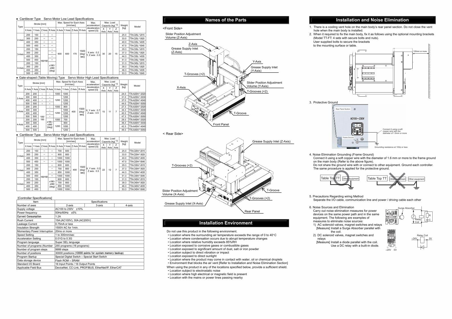
Names of the Parts <Front Side>
< Rear Side>
Installation Environment Do not use this product in the following environment. • Location where the surrounding air temperature exceeds the range of 0 to 40°C • Location where condensation occurs due to abrupt temperature changes • Location where relative humidity exceeds 85%RH • Location exposed to corrosive gases or combustible gases • Location exposed to significant amount of dust, salt or iron powder • Location subject to direct vibration or impact • Location exposed to direct sunlight • Location where the product may come in contact with water, oil or chemical droplets • Environment that blocks the air vent [Refer to Installation and Noise Elimination Section]
When using the product in any of the locations specified below, provide a sufficient shield. • Location subject to electrostatic noise • Location where high electrical or magnetic field is present • Location with the mains or power lines passing nearby
Installation and Noise Elimination 1. There is a cooling vent hole on the main body’s rear panel section. Do not close the vent
hole when the main body is installed. 2. When it required to fix the main body, fix it as follows using the optional mounting brackets
(Model TT-FT: 4 sets with secure bolts and nuts). User supplied bolts to secure the brackets to the mounting surface or table.
3. Protective Ground
Rear Panel Section
Frame Ground
Connect it using a soft copper wire with the diameter of 1.6mm or more
Grounding resistance at 100Ω or less 4. Noise Elimination Grounding (Frame Ground)
Connect it using a soft copper wire with the diameter of 1.6 mm or more to the frame ground on the main body (Refer to the above figure). Do not share the ground wire with or connect to other equipment. Ground each controller. The same procedure is applied for the protective ground.
Table Top TT Table Top TTOther equipment Other equipment Other equipment
5. Precautions Regarding wiring Method
Separate the I/O cable, communication line and power / driving cable each other 6. Noise Sources and Elimination
Carry out noise elimination measures for power devices on the same power path and in the same equipment. The following are examples of measures to eliminate noise sources: 1) AC solenoid valves, magnet switches and relays
[Measure] Install a Surge Absorber parallel with the coil.
2) DC solenoid valves, magnet switches and relays
[Measure] Install a diode parallel with the coil. Use a DC relay with a built-in diode.
120mm or more
Surge Absorber
Relay Coil0V
R
C
+24V
0V+24V+ −
Relay Coil
Z-Axis
Slider Position Adjustment Volume (Z-Axis)
Grease Supply Inlet (Z-Axis)
Y-Axis
T-Grooves (×2)
T-Grooves (×2)
T-Groove
X-Axis
Front Panel
Grease Supply Inlet (Y-Axis)
Slider Position Adjustment Volume (Y-Axis)
T-Grooves (×2)
T-Grooves (×2)
T-Groove
Rear Panel
Grease Supply Inlet (Z-Axis)
Slider Position Adjustment Volume (X-Axis)
Grease Supply Inlet (X-Axis)
Stroke [mm] Max. Speed for Each Axes [mm/sec]
Max. Load Capacity [kg] *2 Type
X Axis Y Axis Z Axis R Axis X Axis Y Axis Z Axis R Axis
Max. acceleration/ deceleration
speed [G] X
Axis Y
Axis Z
Axis
Weight [kg] Model
200 200 – – 1000 1000 24.0 TTA-A2SH-*-2020 300 300 – – 1200 31.0 TTA-A2SH-*-3030 400 400 – – 1200 37.0 TTA-A2SH-*-4040
2-Axis
500 500 – – 1200
1200 44.0 TTA-A2SH-*-5050 200 200 – 1000 800 27.3 TTA-A3SH-*-2020 300 300 – 1000 34.3 TTA-A3SH-*-3030 400 400 – 1200 40.3 TTA-A3SH-*-4040
3-Axis
500 500 – 1200
1200 47.3 TTA-A3SH-*-5050 200 200 1000 700 29.3 TTA-A4SH-*-2020 300 300 900 36.3 TTA-A4SH-*-3030 400 400 1050 42.3 TTA-A4SH-*-4040
4-Axis
500 500
100/ 150
±180 / ±360 [deg] 1200
1200
400 1500 [deg/ sec]
X, Y axis : 0.7 Z axis : 0.5 15 11 7
49.3 TTA-A4SH-*-5050

Monitor LED
CC-Link Communication Connector
Wiring Diagram
I/O Signal Input
*1 Set the input function in I/O Parameters 30 to 45 (input function select 000 to 015), set the port numbers that each set function is to be assigned in I/O Parameters 283 to 298.
*2 The start switch on the front panel would not function if Input Function Select 000 (Program Start) is assigned to any port except for Port No. 000.
*3 The program select switch on the front panel would not function if Input Function Select 007 to 013 (Program Select Switch) is assigned to any port except for Port No. 007 to No. 013.Output
I/O Flat Cable (Accessories) CB-PAC-PIO020
Input and Output Type
Input Section Output Section Item Type Item Type
Input Voltage 24V DC ±10% Load Voltage 24V DC
Input Current 7mA / per output MAX. load current 100mA/1 point 400mA/8 points*6
NPN ON Voltage :MIN. DC16V OFF Voltage :MAX. DC5V Leakage Current MAX. 0.1mA/1 point
Type
ON/OFF Voltage
PNP ON Voltage :MIN. DC8V OFF Voltage :MAX. DC19V
*6 The maximum load current total becomes 400mA for every 8 ports from Output Port No. 316.
N P N
Input Section Output Section
P N P
I/O Circuit diagrams NPN Type PNP Type
Load Load
Pin No. Pin No.+ +
DeviceNet [Refer to the instruction manuals for DeviceNet]
Monitor LED ○Illuminating, ×OFF, ☆Flashing LED Color Indication
Status Indication Description
○ Online, Communication in normal condition Green ☆ Online, No connection established Critical link error Orange ☆ Connection timeout
Green / Orange
☆(Illuminated
by turns) Self-testing
NS
- × Offline / No power supply ○ Normal operation
Green ☆
Configuration setting not established or not complete → test run required
○ An error that cannot be recovered Orange ☆ An error that can be recovered
Green / Orange
☆(Illuminated
by turns) Self-testing
MS
- × No power supply
Connector Name DeviceNet Connector Cable Side MSTB2.5/5-ST-5.08 ABGY AU Enclosed in standard package
Manufactured by PHOENIX CONTACTController Side MSTBA2.5/5-G-5.08 ABGY AU
CC-Link [Refer to the instruction manuals for CC-Link]
Monitor LED ○Illuminating, ×OFF, ☆Flashing LED Color Indication
Status Indication Description
○ Error in reception data to self station Communication setting error (station setting, baud rate setting, etc.)
☆ The station No. and baud rate set values are changed from ones set at the time of reset cancellation (flashes in 0.4sec cycle)
STATUS1 Orange
× In normal communication
STATUS0 Green ○ Turns on when communication is started, and turns off when communication is disconnected for the specified time
Connector Name CC-Link Connector Cable Side MSTB2.5/5-ST-5.08AU Enclosed in standard package
Manufactured by PHOENIX CONTACT
Controller Side MSTBA2.5/5-G-5.08AU
Pin No.
Electric wire color
Port No.
Function at Standard Setting (when delivered)
1B Brown 3 316 General-purpose output
2B Red 3 317 General-purpose output
3B Orange 3 318 General-purpose output
4B Yellow 3 319 General-purpose output
5B Green 3 320 General-purpose output
6B Blue 3 321 General-purpose output
7B Purple 3 322 General-purpose output
8B Gray 3 323 General-purpose output
9B White 3 324 General-purpose output
10B Black 3 325 General-purpose output
11B Brown 4 326 General-purpose output
12B Red 4 327 General-purpose output
13B Orange 4 328 General-purpose output
14B Yellow 4 329 General-purpose output
15B Green 4 330 General-purpose output
16B Blue 4 331 General-purpose output
17B Purple 4 –
18B Gray 4 –
19B White 4 – I /O power supply 0V
20B Black 4 – I /O power supply 0V
Reference
It is set to general-purposed output at delivery, and input function can be changed in I/O parameter settings.
Parameter*4
No. Parameter name Function
46 331
Output function selection 300*5 Output function selection 300 (area 2) 0: General-purpose output
1: Output error of operation-cancellation level or higher (ON) 2: Output error of operation-cancellation level or higher (OFF) 3: Output error of operation-cancellation level or higher +
emergency stop (ON) 4: Output error of operation-cancellation level or higher +
emergency stop (OFF)
47 332
Output function selection 301*5 Output function selection 301 (area 2)
0: General-purpose output 1: READY output (PIO trigger program can be run) 2: READY output (PIO trigger program can be run and error of
operation-cancellation level or higher is not present) 3: READY output (PIO trigger program can be run and error of
cold-start level or higher is not present)
48 333
Output function selection 302*5 Output function selection 302 (area 2)
0: General-purpose output 1: Emergency stop output (ON) 2 :Emergency stop output (OFF)
49 334
Output function selection 303*5 Output function selection 303 (area 2)
0:General-purpose output 1: AUTO mode output 2: Output during automatic operation (The setting to “1“ the other
parameter No.12) 50 335
Output function selection 304*5 Output function selection 304 (area 2)
0: General-purpose output 1: Output if all valid axes are at home (= 0) 2: Output if all valid axes completed home return (coordinates
confirmed) 3: Output if all valid axes are at preset home coordinates
51 336
Output function selection 305 Output function selection 305 (area 2)
0: General-purpose output 2: Axis 1 in-position output
52 337
Output function selection 306 Output function selection 306 (area 2)
0: General-purpose output 2: Axis 2 in-position output
53 338
Output function selection 307 Output function selection 307 (area 2)
0: General-purpose output 2: Axis 3 in-position output
54 339
Output function selection 308 Output function selection 308 (area 2) 0: General-purpose output
55 340
Output function selection 309 Output function selection 309 (area 2) 0: General-purpose output
56 341
Output function selection 310 Output function selection 310 (area 2) 0: General-purpose output
57 342
Output function selection 311 Output function selection 311 (area 2) 0: General-purpose output
58 343
Output function selection 312 Output function selection 312 (area 2) 0: General-purpose output
59 344
Output function selection 313 Output function selection 313 (area 2) 0: General-purpose output
60 345
Output function selection 314 Output function selection 314 (area 2) 0: General-purpose output
61 346
Output function selection 315 Output function selection 315 (area 2) 0: General-purpose output
Pin No.
Electric wire color
Port No.
Function at Standard Setting (when delivered)
1A Brown 1 – I /O power supply+24V
2A Red 1 – I /O power supply+24V
3A Orange 1 –
4A Yellow 1 –
5A Green 1 016 General-purpose input
6A Blue 1 017 General-purpose input
7A Purple 1 018 General-purpose input
8A Gray 1 019 General-purpose input
9A White 1 020 General-purpose input
10A Black 1 021 General-purpose input
11A Brown 2 022 General-purpose input
12A Red 2 023 General-purpose input
13A Orange 2 024 General-purpose input
14A Yellow 2 025 General-purpose input
15A Green 2 026 General-purpose input
16A Blue 2 027 General-purpose input
17A Purple 2 028 General-purpose input
18A Gray 2 029 General-purpose input
19A White 2 030 General-purpose input
20A Black 2 031 General-purpose input
Reference It is set to general-purposed input at delivery, and input function can be changed in I/O parameter settings.
Parameter*1 No. Parameter name Function
30 Input function selection 000※2 1: Program Start
31 Input function selection 001 0: General-purpose input 1: Software reset signal
32 Input function selection 002 0: General-purpose input 1: Servo ON signal
33 Input function selection 003 0: General-purpose input 1: Program Automatic Start runs with power-on
reset / software reset in AUTO Mode 2: Auto-start program signal
34 Input function selection 004 0: General-purpose input 1: All servo axis soft interlock (OFF level)
35 Input function selection 005 0: General-purpose input 1:Operation-pause reset (ON edge)
36 Input function selection 006 0: General-purpose input 1: Operation-pause reset signal (OFF level)
37 Input function selection 007※3 0: General-purpose input 1: Program number specification (LSB)
38 Input function selection 008※3 0: General-purpose input 1: Program number specification (Bit 2)
39 Input function selection 009※3 0: General-purpose input 1: Program number specification (Bit 3)
40 Input function selection 010※3 0: General-purpose input 1: Program number specification (Bit 4)
41 Input function selection 011※3 0: General-purpose input 1: Program number specification (Bit 5)
42 Input function selection 012※3 0: General-purpose input 1: Program number specification (Bit 6)
43 Input function selection 013※3 0: General-purpose input 1: Program number specification (MSB: Bit 7) 2: Error reset (ON edge)
44 Input function selection 014 0: General-purpose input 1: Driving source cutoff cancellation input (ON edge)
45 Input function selection 015 0: General-purpose input 1: Home return of all valid axes (ON edge) 2: Home return of all valid incremental axes (ON edge)
No. Signal Name
Cable Color Wiring
1A 24V Brown-12A 24V Red-13A - Orange-14A - Yellow-15A IN0 Green-16A IN1 Blue-17A IN2 Purple-18A IN3 Gray-19A IN4 White-110A IN5 Black-111A IN6 Brown-212A IN7 Red-213A IN8 Orange-214A IN9 Yellow-215A IN10 Green-216A IN11 Blue-217A IN12 Purple-218A IN13 Gray-219A IN14 White-220A IN15 Black-2
Flat Cable A(Press Welding)
No. Signal Name
Cable Color Wiring
1B OUT0 Brown-32B OUT1 Red-3 3B OUT2 Orange-34B OUT3 Yellow-35B OUT4 Green-36B OUT5 Blue-37B OUT6 Purple-38B OUT7 Gray-39B OUT8 White-310B OUT9 Black-311B OUT10 Brown-412B OUT11 Red-4 13B OUT12 Orange-414B OUT13 Yellow-415B OUT14 Green-416B OUT15 Blue-417B - Purple-418B - Gray-419B OV White-420B OV Black-4
Flat Cable B(Press Welding)
AWG28
Pins No. 1A, 2A(Note 2)
Input Terminal Ports No.016 to 031
Inte
rnal
Pow
er
External Power Source
560Ω
3.3KΩ
+-
24V DC +10%
Pins No. 1A, 2A (Note 2)
Pins No. 19B, 20B(Note 2)
Ports No. 316 to 331
LoadOutput
Terminal
External Power Source
Surge Absorber
Output Circuit
D
10Ω
24V DC +10%+-
Inte
rnal
Pow
er
Inte
rnal
Pow
er
External Power Source
560Ω
3.3KΩ
+-
24V DC +10%
Pins No. 19B, 20B (Note 2)
Ports No.016 to 031
Input Terminal
Inte
rnal
Pow
er
Pins No. 1A, 2A(Note 2)
Pins No. 19B, 20B (Note 2)
Ports No. 316 to 331
Output Terminal
Load
External Power Source
Surge Absorber
Output Circuit
10Ω
24V DC +10%+-
Input and output are the equivalent circuit that shows the logic.
Flat Cable (20-core) × 2
20A 20B
1A 1B
Half Pitch MIL SocketHIF6-40D-1.27R (Hirose Electric)
A
B
L
No treatment conducted
No treatment conducted
Monitor LED
RD
WT None
BL BK
DeviceNet Communication Connector
Shield
BL (CAN L)
RD (V+)
WT (CAN H)
BK (V-)
Slave Devices XSEL
V+
Drain(Shield)
CAN_H
CAN_L
V-
RD
WT
BL
BK
RD
WT
BL
BK
V+
Drain(Shield)
CAN_H
CAN_L
Class D grounding(Formerly Class-III grounding: Grounding resistance at 100Ω or less)
V+
Drain(Shield)
CAN_H
CAN_L
V-
RD
WT
BL
BK
Communication power needs to be supplied by an external device.
Terminal Resistance is required to be mounted on the terminal.
V-
Terminal Resistance121Ω
Master Unit Terminal Resistance121Ω
24V Power Supply Grounding resistance at 100Ω or less
*4 Set the input function in I/O Parameters 46 to 61 (output function select 300 to 315), set the port numbers that each set function is to be assigned in I/O Parameters 299 to 314. Also, it is available to set the output function in I/O Parameters 331 to 346 (Output Function Select 300 Area 2 to 315 Area 2), and set the port numbers to assign each set function in I/O Parameters 315 to 330. In case of outputting the system output to I/O in the table above, use Output Function Select Area 2.
*5 LEDs would not function in case that Parameters 46 to 50 are set as general-purposed output, or change is made to the port number assignment in Parameters 299 to 303 as Output Function Select 300 to 304 are assigned to the LEDs on the panel window.
Front Panel Wiring Layout
Back Panel Wiring Layout
Variety of Fieldbus (Options) IO Flat Cable (Accessories)
Model: CB-PAC-PIO020
Model: TB-01-S
Touch Panel Teaching (Option)
Model: IA-101-X-MW IA-101-TTA-USB IA-101-X-USBMW
IA-101-XA-MW
PC Software (Option)
Emergency Stop Switch
Electromagnetic Contactor
Enable Switch
PC Connection Cable (Enclosed in PC Software) Model: CB-ST-E1MW050 (5m)
CB-SEL-USB030 (3m) CB-ST-AIMW050 (5m)
AC100 to 230V Select from those below for power supply cable • Only with plug on main
unit side • Power supply cable
for 100V AC (2m) • Power supply cable
for 200V AC (2m)
Protective Grounding
Extension I/O Slot
Standard I/O Service Power Supply Connector
* Emergency stop switch, enable switch, electromagnetic contactor and other considered devices are to be in layout if necessary. Operation is available with the settings at delivery (short-circuit treatment).
Dummy Plug
Model: DP-2 * Enclosed in global type and PC Software (IA-101-TTA-USB)

Monitor LED
PROFIBUS-DP Communication Connector
PROFIBUS-DP [Refer to the instruction manuals for PROFIBUS-DP]
Monitor LED ○Illuminating, ×OFF, ☆Flashing LED Color Indication
Status Indication Description
○ Online (Communication in normal condition)Green ☆ Online (Cleared)
☆ (1HZ) Parameterizing data error Orange
☆ (2HZ) Configuration error
Operation Mode
- × Online / No power supply ○ Completed Green ☆ Completed (with network check event)
Orange ○ exceptional error Status
- × No power supply / Initializing not executed
Connector Name PROFIBUS-DP Connector Cable Side 9-pin D-sub Connector (Male) Please prepare separately Controller Side 9-pin D-sub Connector (Female)
EtherNet/IP [Refer to the instruction manuals for EtherNet/IP]
Connector Name EtherNet/IP Connector Cable Side 8P8C Module Plug Controller Side 8P8C Module Jack
Pin No. Signal Name Description Applicable Cable Diameter
1 TD+ Data transmitted +
2 TD- Data transmitted -
3 RD+ Data received +
4 - Not used
5 - Not used
6 RD- Data received -
7 - Not used
8 - Not used
For EtherNet cable, use a straight STP cable that possesses the performance of Category 5e or more.
EtherCAT [Refer to the instruction manuals for EtherCAT] Monitor LED ○Illuminating, ×OFF, ☆Flashing
Connector Name EtherCAT ConnectorCable Side 8P8C modular plug Controller Side 8P8C modular jack
Starting Procedures When using this product for the first time, pursue work while making sure to avoid omission and incorrect wiring by referring to the procedure below.
Troubleshooting The following alarm displays are frequently generated at the start-up operation. Deal with each of them referring to the following table. Status display Status contents Cause and Remedy During
Emergency-stop It is not an alarm. • It is caused when the emergency stop button is not cleared on the
front panel. Clear it. • It is generated when the emergency stop switch in the teaching
pendant or the personal computer application software is not cancelled. In such case, cancel it.
• It is generated when the personal computer cable is not connected to the emergency stop box.
Status display Status contents Cause and Remedy Deadman switch OFF It is not an alarm.
• It generated when the AUTO/MANU switch has been set to “MANU” and the personal computer or the teaching pendant is not connected. Connect the personal computer or the teaching pendant or set the AUTO/MANU switch to “AUTO”.
• When the actuator is to be started up, hold the deadman switch on the teaching pendant to turn it on.
AC Power nterruption Momentary Power Failure Power Voltage Drop
It is generated when the power voltage is not supplied. Check the power supply.
24V I/O Error It is generated when the +24V power for I/O is not supplied. Check the power supply. (Procedure for starting up I/O 24V power unit without connection) Set both the I/O parameter No. 10 and No. 12 to “0”. In this case, the I/O connection is invalid.
Field Bus Error It is generated when the field bus link connection is not established. Check the link cable connection, I/O parameter and PLC parameter settings. (How to start up the controller without connecting the field bus) Set both the I/O parameter No. 10 and No. 12 to “0”.
Head Office: 577-1 Obane Shimizu-KU Shizuoka City Shizuoka 424-0103, JapanTEL +81-54-364-5105 FAX +81-54-364-2589
website: www.iai-robot.co.jp/
Ober der Röth 4, D-65824 Schwalbach am Taunus, GermanyTEL 06196-88950 FAX 06196-889524
SHANGHAI JIAHUA BUSINESS CENTER A8-303, 808, Hongqiao Rd. Shanghai 200030, ChinaTEL 021-6448-4753 FAX 021-6448-3992
website: www.iai-robot.com
Technical Support available in USA, Europe and China
Head Office: 2690 W. 237th Street, Torrance, CA 90505TEL (310) 891-6015 FAX (310) 891-0815
Chicago Office: 110 East State Parkway, Schaumburg, IL 60173TEL(847) 908-1400 FAX (847) 908-1399
TEL (678) 354-9470 FAX (678) 354-9471website: www.intelligentactuator.com
Atlanta Office: 1220 Kennestone Circle, Suite 108, Marietta, GA 30066
825 PhairojKijja Tower 12th Floor, Bangna-Trad RD., Bangna, Bangna, Bangkok 10260, ThailandTEL +66-2-361-4458 FAX +66-2-361-4456
LED Color Indication Status Indication Description
○ Communication in normal condition (in OPERATION condition)
☆ 0.2sec cycle Configuration condition (in PRE-OPERATION condition) Green
☆ ON 0.2sec / OFF 1sec
Configuration complete condition (in SAFE-OPERATION condition)
Orange ○ Error impossible to recover
RUN
- × In initialized condition (in INIT condition) / No power supply
○ Error impossible to recover ☆ 0.2sec cycle Network construction error Orange☆ ON 0.2sec
2times / OFF 1secCommunication error (Watch dock time-out)
ERR
- × No power supply / No error
○ Linked (Communication traffic not detected) Green
☆ 0.05sec cycle Linked (Communication traffic detected )Link/
Activity - × No link / No power supply
No→
• To ensure safety, it is recommended that safety speed be enabled during initial movements.
Point Check Item• Is frame ground (FG) connected? • Has the noise countermeasure been taken?
↓Yes
No →
↓
→
Power Supply and Alarm CheckConnect the personal computer or teaching pendant, set the AUTO/MANU switch to the [MANU] side and inject the power.
Deal with each condition depending on the status display.
Servo ON Turn ON the servo motor with the personal computer or teaching pendant operation.
Check ItemCheck that SV is ON in Position Edit Window on PC software or teaching pendant.
During the alarm output, confirm the alarm description and deal with the condition with the personal computer or teaching pendant operation.
No →
→
↓
↓Yes
Check ItemIs the status display showing [ ] ?
Parameter Settings [Refer to Chapter 6]Set the parameters including I/O parameter with the personal computer or teaching pendant operation. [Reference] Set I/O Parameters No. 10 to 11 to 0 (Not to Monitor Errors) if starting up the system without connecting I/O 24V power supply for PIO Type. Set either of I/O Parameter No. 18 or 235 to 0 (Not to Monitor Errors) if starting up the system without connecting Fieldbus for Fieldbus Type.
Check of Packed ItemsHas everything been received?
↓
↓Yes
No→
Confirming the operation of the actuatorConfirm that the full stroke operation is performed without any trouble with the jog operation.
↓Yes
Check of Safety CircuitDoes the emergency stop circuit (drive cutoff circuit) work properly and turn the servo OFF?
Installation and WiringPerform the installation and wiring according to the instruction manual and this guide.
Contact us or our distributor.
←Yes
Check the emergency stop circuit.
Set-up for operation is complete. Establish the setting that suits to your operation patterns.
5
1
9
6
Cable
Shield
Red B line (Positive side)
Green A line (Negative side)
WT (DB)BL (DA)
Shield (SLD)
YW (DG)
Slave Devices XSEL
SLD and FG are internally connected.
Terminal Resistance is required to be mounted on the terminal.
The terminal resistor differs depending on the type of the dedicated cable for CC-Link.• Cable FANC-SBH···130Ω1/2W (High Performance Cable dedicated for CC-Link)• Cable FANC-SB······110Ω1/2W (CC-Link Dedicated Cable)
Master Unit Terminal Resistance
TerminalResistance
Class D grounding(Formerly Class-III grounding: Grounding resistance at 100Ω or less)
Grounding resistance at 100Ω or less
Controller Side Connector Front View
EtherNet Straight Cable Category 5e or more Double shielded cable braided with aluminum foil recommended
Master Unit
Switching Hub
Slave Device
EtherNet/IP Specification
Manual No.: ME0321-5A
Link/Activity
EtherCATポート(IN)
Link/Activity
EtherCATポート(OUT)
1 8
EtherCAT Port (OUT)
Link/Activity
EtherCAT Port (IN)
Link/Activity
Recommended