i
FireFinderTM
Fire Alarm Control Panel (NZS 4512-2003)
Installation, Commissioning &
Operation
MAN 2335-5

Page ii
FIREFINDER INSTALLATION COMMISSIONING & OPERATION
Responding To An Alarm
1. Indicators -Alarm Indicator Flashing. -Location of Alarm on LCD Display. -First Alarm Displayed.
2. Isolate External Bell Isolate Warning System
3. Acknowledge Alarm
4. Isolate Alarm
ACKNOWLEDGE to confirm ISOLATE”
5. If multiple alarms exist repeat 3 and 4 for second alarm and so on.
6. To Reset Panel
ACKNOWLEDGE to confirm RESET
EXTERNAL BELLISOLATE
PressWARNING SYS
ISOLATE
Press
ACKNOWLEDGE
Press
ISOLATE
Press
ACKNOWLEDGE
Press
RESET
PressPress
ACKNOWLEDGE
Press

Page iii
FIREFINDER INSTALLATION COMMISSIONING & OPERATION
Table Of Contents Page No
1 Non Disclosure Agreement ........................................................................................................................ 1
2 About This Manual ..................................................................................................................................... 2
2.1 Purpose .......................................................................................................................... 2
2.2 Scope .............................................................................................................................. 2
2.3 References...................................................................................................................... 2
3 System Overview ....................................................................................................................................... 3
4 FireFinderTM Description ............................................................................................................................ 4
4.1 Ancillary Services .......................................................................................................... 6
5 Placing The System Into Operation .......................................................................................................... 7
5.1 Unpacking....................................................................................................................... 7
5.2 Anti-Static Precautions .................................................................................................. 7
5.3 Working On The System ................................................................................................ 7
5.4 The Cabinet .................................................................................................................... 7
5.5 Mounting The Cabinet .................................................................................................... 7
5.6 Operational Parameters ................................................................................................. 8
5.7 Cabling Recommendations............................................................................................ 8
5.8 RS 232 Modem / Debug Interfacing ............................................................................... 9
5.9 AC Mains Installation ..................................................................................................... 9
5.10 Connecting the Power .................................................................................................... 9
5.11 Main Board BRD85MBA ...............................................................................................11
5.12 Front Panel Board 302 -690...........................................................................................12
5.13 Main CPU .......................................................................................................................13
5.14 Slave CPU ......................................................................................................................14
5.15 Brigade / PSU Monitor Board ........................................................................................15
5.15.1 Brigade Board & Battery Connections ..........................................................17
5.15.2 Brigade Board Auxiliary 27 Volt Power .........................................................17
5.15.3 Connecting a Bell or Sounder to the Brigade Board ....................................17
5.15.4 Connecting the Alert / Evacuation Amplifier .................................................18
5.15.5 Brigade Board Relay Output Connections ....................................................20
5.15.6 Signal Generating Device ...............................................................................20

Page iv
FIREFINDER INSTALLATION COMMISSIONING & OPERATION
6 Compatible FireFinderTM Modules........................................................................................................... 21
6.1 Conventional Zone Board .............................................................................................22
6.2 Apollo Loop Termination Board ...................................................................................23
6.3 16/16 Input / Output Board ............................................................................................24
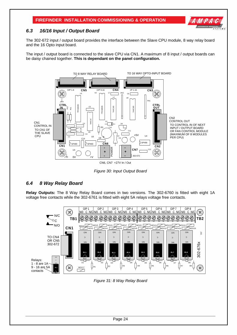
6.4 8 Way Relay Board ........................................................................................................24
6.5 16 Way Input Board .......................................................................................................25
6.6 Serial Relay Board .........................................................................................................25
6.7 Fire Fan Module BRD25FCB .........................................................................................26
6.8 Fan Termination Board BRD25FTB ..............................................................................26
6.9 32 Zone LED Mimic Board ............................................................................................27
6.10 Valve Display Module ....................................................................................................28
6.11 Pump Display Module ...................................................................................................29
6.12 Sounder / Bell Controller Board ...................................................................................30
6.13 Printer ............................................................................................................................31
6.13.1 Indicators and Buttons ...................................................................................31
6.13.2 Maintenance....................................................................................................32
6.13.3 Printer Connections and Jumpering..............................................................33
6.13.4 Printer 5 Volt Power Supply ( 302-713 ) .........................................................33
7 Agent Release Control.............................................................................................................................. 34
7.1 Operation .......................................................................................................................34
7.2 Agent Release Module BRD25ARB -A ..........................................................................36
7.3 Local Control Station ( LCS ) BRD25ARB -B................................................................37
7.4 Panel Indicators ............................................................................................................37
7.5 Agent Termination Board BRD25ATB ..........................................................................39
7.6 Interface Wiring .............................................................................................................40
7.7 Warning Signs ...............................................................................................................42
8 Expanding the System & Networking ..................................................................................................... 44
8.1 Expansion Controller ....................................................................................................44
8.2 Networking ....................................................................................................................44
8.3 Expansion Board ...........................................................................................................47
8.4 Controller Interface Card ..............................................................................................48
8.5 Network Interface Card .................................................................................................48
8.6 LED Mimic Board...........................................................................................................49
8.7 Remote Expansion LED Board .....................................................................................51
8.8 Liquid Crystal Display Repeater Panel .........................................................................53

Page v
FIREFINDER INSTALLATION COMMISSIONING & OPERATION
9 FireFinderTM Operation ............................................................................................................................. 54
9.1 The Control Panel ..........................................................................................................54
9.2 The Default LCD Display ...............................................................................................57
9.3 Accessing Functions and Menus .................................................................................57
9.4 Function Menu and Access Levels...............................................................................58
9.5 The Main Menu ..............................................................................................................58
9.5.1 Status Menu ....................................................................................................58
9.5.2 Testing Menu ..................................................................................................61
9.6 Function Menu ( Level 2 / 3 ) .........................................................................................62
9.6.1 Setting the Function Date Facility..................................................................62
9.6.2 Setting the Function Time Facility .................................................................62
9.6.3 Setting the Function Daynight Facility ..........................................................62
9.6.4 Function Logs Facility ....................................................................................63
9.6.5 The Function Test Facility ..............................................................................63
9.6.6 Function Manual I/O Control ..........................................................................64
9.6.7 Function Programming ..................................................................................65
9.6.8 Conventional Zone Programming ..................................................................65
9.6.9 Device Programming ......................................................................................66
9.6.10 Input Programming.........................................................................................67
9.6.11 Output Programming ......................................................................................67
9.6.12 Manual Control Point ( MCP ) .........................................................................67
9.6.13 Sub Address ...................................................................................................67
9.6.14 Watchdog ........................................................................................................68
9.6.15 Self Learn ........................................................................................................68
9.6.16 Extra Devices Detected ..................................................................................68
9.6.17 Mismatch Detected .........................................................................................69
9.6.18 Function Passwords .......................................................................................69
9.6.19 Forgotten Passwords .....................................................................................69
10 Incoming Fire Alarm Signal ..................................................................................................................... 70
11 Accessing a Loop, Sensor or Zone ........................................................................................................... 71
12 List of Compatible Devices ...................................................................................................................... 72
13 Certification Information ......................................................................................................................... 73
14 Troubleshooting Chart ............................................................................................................................. 74
15 Binary Address Setting ............................................................................................................................ 75
16 Glossary of Terms .................................................................................................................................... 76
17 Definitions ................................................................................................................................................ 77
18 Quick Reference Guides ........................................................................................................................... 78
19 Battery and Power Supply Capacity Calculation ................................................................................... 80

Page 1
FIREFINDER INSTALLATION COMMISSIONING & OPERATION
1 Non Disclosure Agreement This contract has been entered into by the person or company user of this document (hereafter called the Trader) and AMPAC Technologies (hereafter called AMPAC) of 97 Walters Drive, Osborne Park Western Australia 6017. Under terms and conditions as specified hereunder. Whereas AMPAC and the Trader for their mutual benefit and pursuant to a working relationship which may be established, anticipate that AMPAC will disclose in the form of this document, information of a secret, or confidential or proprietary nature (hereinafter collectively referred to as Proprietary Information). Whereas AMPAC desires to ensure that the confidentiality of any Proprietary Information is maintained in accordance with the terms of this Agreement; NOW, THEREFORE, in consideration of the foregoing premises, and the mutual covenants contained herein, the Trader hereby agrees as follows: 1. The Trader shall hold in trust and confidence, and not disclose to any person outside its organisation,
any Proprietary information which is disclosed to the Trader by AMPAC under this Agreement. Proprietary Information disclosed under this Agreement may be used by the Trader only for the purpose of carrying out work on or with AMPAC supplied equipment and may not be used for any other purpose whatsoever.
2. The Trader shall disclose Proprietary Information received by AMPAC under this Agreement to
persons within its organisation only if such persons are legally bound in writing to protect the confidentiality of such Proprietary Information.
3. The undertakings and obligations of the Trader under this Agreement shall not apply to any Proprietary
Information which :
1. Is disclosed in a printed publication available to the public, is described in patent anywhere in the world, or is otherwise in the public domain at the time of disclosure;
2. Is generally disclosed to third parties by AMPAC without restriction on such third parties;
3. Is shown by the Trader to have been in its possession prior to the receipt thereof from AMPAC;
4. Is approved for release by written authorisation of AMPAC; or
5. Is not designated by AMPAC in writing or by appropriate stamp or legend to be of a secret,
confidential or proprietary nature. 4. This Agreement will be binding upon and inure to the benefit of the parties hereto, and their respective
successors and assigns. 5. This Agreement, and all rights and obligations hereunder, shall expire on the 10th anniversary of the
date of issue of this document. These terms are accepted by the Trader on receipt and retention of this document.

Page 2
FIREFINDER INSTALLATION COMMISSIONING & OPERATION
2 About This Manual
2.1 Purpose The purpose of this manual is to assist the technician in the installation, commissioning and operation of
the FireFinderTM FACP.
2.2 Scope The information within this manual is only available to and for the use of personnel engaged in the
installation and operation of the FireFinderTM FACP.
FireFinder has been designed and manufactured from high quality components to comply with major world standards. To ensure these standards are not compromised in any way installation staff and operators should;
1. be qualified and trained for the task they undertake;
2. observe anti-static pre-cautions at all times;
3. be aware that if a problem is encountered or there is any doubt with respect to the operational parameters of the installation the supplier should be contacted; and
2.3 References
FireFinderTM Technical Manual AMPAC Product Data Sheets New Zealand Standard: NZS4512 2003
Figure 1: A Typical Application
R4
WARNING SYSISOLATE
EXTERNAL BELLISOLATE
PREVIOUS NEXTACKNOWLEDGE ISOLATERESET
WARNINGSYS FAULT
TEST MODE
SYSTEM FAULT
EARTH FAULT
AIF ACTIVE
AUX ALARM
PRE-ALARM
SUPPLY FAULT
POWER ON
ALARM
FAULT
ISOLATED
DE-ISOLATE
FAULTOUTPUT ISOLATE
AUXILIARYFAULT / ISOLATE
OUTPUTDELAY ACTIVE
LOOP
ZONE
SENSOR
DISPLAY TO
TUV7
4JKL
ABC1
DEF2
5MNO
8WXYZ
0SPACE
3GHI
6PQRS
9SYMB
ENTER FUNCTIONMENU
CANCEL ENTRY
FinderTM
FIREFIGHTER FACILITY
Fire
E.O.L3K3
CONVENTIONAL ZONEUSING CONVENTIONAL DETECTORS
AND BASES
CONVENTIONAL ZONE CIRCUIT
ADDRESSABLE LOOP
ISOLATORION OPTICAL HEAT
ANALOGUE DETECTORSMANUAL CALLPOINT ( MCP )
ISOLATOR
E.O.L6K2
FIREALARM
PRESS HERE
TO BREAK
EXTERNAL COMMUNICATIONLOOP
4K7
4K
7
FIREALARM
PRESS HERE
TO BREAK
FIREALARM
PRESS HERE
TO BREAK
S T O PA UT O
R U NS T O PA UT O
R U NS T O PA UT O
R U N
F AN
S T O P
F AN
FAULT
F AN
R U N
F AN
S T O P
F AN
FAULT
F AN
R U N
F AN
S T O P
F AN
FAULT
F AN
R U N
F AN
S T O P
F AN
FAULT
F AN
R U N
A UT OS T O PR U N
HIGH LEVELINTERFACE
HIGH LEVELINTERFACE
ANCILLARYSERVICES
AS PER INPUT 1
AS PER INPUT 1
20KEOL
4K7
N/O INPUTSWITCH
RELAY O/P 1
IN-1
IN-2
IN-3
C1
NC
NO
C2
NC
NO
C3
NC
NO
RELAY O/P 2
RELAY O/P 3
FIREFINDERFACP
SINGLE INPUTDEVICE
FLOW SWITCH
E.O.L 20K
LOOP SOUNDER
L1
L2
E.O.L 10K
SOUNDER
SOUNDER CONTROL
+-
+24V DC
N/O C N/C
RELAYOUTPUT
AUX OUTPUTS
INPUT/OUTPUT UNIT
CONVENTIONAL DETECTORSMAXIMUM OF 20
ZONE MONITOR
OUT
IN
SPECIFICATIONS:MAX LENGTH = 2KMMAX RESISTANCE = 50ohmsMIN CABLE SIZE = 1.5mm²
MONITORED INPUT
+-
+24V DC
THREE INPUT / OUTPUTDEVICE
E.O
.L 2
0K
M ENU
PREVIOUS NEXT BUZZERMUTE
PRE-ALARMISOLATEDEFECTALARMNORMAL
C L O SEDO P E N
C L O SEDO P E N
C L O SEDO P E N
C L O SEDO P E N
C L O SED
C L O SED
C L O SEDO P E N
C L O SEDO P E N
C L O SEDO P E N
C L O SEDO P E N
C L O SEDO P E N
C L O SEDO P E N
C L O SEDO P E N
C L O SEDO P E N
O P E N
C L O SEDO P E N
O P E N
C L O SEDO P E N
Page 3
FIREFINDER INSTALLATION COMMISSIONING & OPERATION
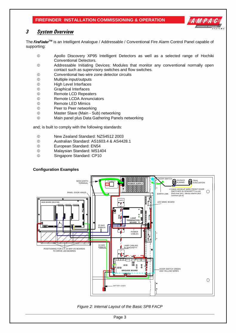
3 System Overview
The FireFinderTM is an Intelligent Analogue / Addressable / Conventional Fire Alarm Control Panel capable of supporting:
Apollo Discovery XP95 Intelligent Detectors as well as a selected range of Hochiki Conventional Detectors.
Addressable Initiating Devices: Modules that monitor any conventional normally open contact such as supervisory switches and flow switches.
Conventional two wire zone detector circuits
Multiple input/outputs
High Level Interfaces
Graphical Interfaces
Remote LCD Repeaters
Remote LCDA Annunciators
Remote LED Mimics
Peer to Peer networking
Master Slave (Main - Sub) networking
Main panel plus Data Gathering Panels networking and; is built to comply with the following standards:
New Zealand Standard: NZS4512 2003
Australian Standard: AS1603.4 & AS4428.1
European Standard: EN54
Malaysian Standard: MS1404
Singapore Standard: CP10
Configuration Examples
+ -
+-
a b c
ON
1 2 3 4 5 6 7 8
CN
2
+ -+ -
+ - AUXI LI ARY
+
BA
T
-+
I
N
-D
BA
/M
CP
DO
OR
S
W
BELL2BELL1FAULTVALVE M O NBATT FAI L
NO C NCNO C NCNO C NCNO C NC
NO C NC+ - + - NO C NC+ -+ -
ALARM I SO LATE
C
SG
D
II
W ARN SYSAUX PO W ER O / P
C1
5
TB
10
M1
M2
F6
F2
F4F
5
F1
TB4
D3
TB
11
RL
2
C4
CN
2
CN
1
L1
L2
TB
6
TB5
CN
6
+
C2
3
TB
3
RL
1
CN
5D1
5C
1
C1
2
TB
2
F7
F8
U7
R1
4
MAIN BOARD (302-674D)
O O O
O O OO O O
O O O
O O O
O O O
O O OO O O
O O O
O O O
O O O
O O OO O O
O O O
O O O
O O OO O O
O O O
O O O
O O O
O O OO O O
O O O
O O O
O O O
O O OO O O
O O O
O O O
O O O
O O OO O O
30
2-7
350
Sept 1998
API-706
R1
D1
D2
R2
U7
+
C9
+ C10
C5
U1
R3
R4
D3
D4
D21
R22
D6
D5
R6
R5
CN6
D9
D8
D7
R9
R8
R7
U2
C6
R24
D12
D11
D10
R13
R12
R11
R10
C3
CN1 R21
C1
R23
U3
D15
D14
D13
R16
R15
R14 U5C7
C8
U6
C12
D17
D16
D18
R19
R18
R17C11
R25
U4
D20
D19
R20
CN2
BA
B
BA
TX
1C
N2
CN
3C
N1
TB
2T
B1
CN
4
F1
L2
+L
1-
L2
+L
1-
L2
+L
1-
L2
+L
1-
PO
WE
R
3A
PDL SWITCH
DANGER240V
V A
DJ
V+
V-
GN
DN
(AC
)L
(AC
)
MAIN EARTHTERMINAL
LAMP CABLINGIN SPAGHETTI
POWERCABLES
DOOR SWITCH GREENAND YELLOW WIRES
= 0.6mm HOOKUP WIRE FRONT DOOR SWITCHES IN SPAGHETTI to cn6 (trial evac pin1, silence alarms pin2 common pin 6)
LAMPS
BATTERY LEADS
10 WAYRIBBON
20 WAYRIBBON
LOOPTERMINATION
BOARD
BRIGADE BOARD
LED MIMIC BOARD
TRIALEVACUATION
SILENCEALARMS
DOOR SWITCH
EARTH LINKPANEL DOOR HINGE
POWER SUPPLY
POSITIONING FOR 3 X 16 WAY I/O BOARDSTO DRIVE LED BOARDS
Figure 2: Internal Layout of the Basic SP8 FACP

Page 4
FIREFINDER INSTALLATION COMMISSIONING & OPERATION
TRIALEVACUATION
SILENCEALARMS
FIRE
DBA
DEFECT
NORMAL
ZONE 1
ZONE 2
ZONE 3
ZONE 4
YOU AREHERE
TRIAL EVACUATIONKEY SWITCH
SILENCEALARMSBRIGADE
USE ONLYKEYSWITCH
FACP LCDVIEWING WINDOW
FIRE
DBA
DEFECT
NORMAL
ZONE 1
ZONE 2
ZONE 3
ZONE 4SITE PLANDOOR LOCKS
Figure 3: SP8 Rear Service - Rear View Figure 4:SP8 Rear Service – Front View
FIRE
DBA
DEFECT
NORMAL
ZONE 1
ZONE 2
ZONE 3
ZONE 4
ZONE 5
ZONE 6
ZONE 7
ZONE 8
ZONE 9
ZONE 11
ZONE 12
ZONE 13
ZONE 14
ZONE 15
ZONE 10
ZONE 16
SILENCEALARMSBRIGADE
USE ONLY
EVACUATION
FIRE
DBA
DEFECT
NORMAL
ZONE 1
ZONE 2
ZONE 3
ZONE 4
SILENCEALARMSBRIGADE
USE ONLYKEYSWITCH
EVACUATIONKEYSWITCH
KEYEDDOORLOCK
Figure 5: SP2 / 4 Front View
4 FireFinderTM Description The following description does not relate to specific cabinets as the size of each cabinet will vary with the amount of hardware fitted.
The heart of the FireFinder™ consists of two boards collectively known as the Controller. These boards are the Main Board (BRD85MBA) and the CPU board (BRD85CPU). Combining these two boards with a
front panel (302-690) forms the basis for a FireFinder™ FACP. A single FireFinder™ Controller without an
expansion board has the capacity to interface to four (4) FireFinder™ Slave CPU’s modules. Each of these Slave CPU’s can interface to 16 Zone Conventional Termination Boards, Loop Termination Boards or Input/Output Boards as well as communicate with the Brigade / PSU Monitor Board (302-673). The Main Board (BRD85MBA) has the Slave CPU Board for the first Loop Termination Board and the
provision for mounting of up to three additional FireFinder™ Slave CPU’s. The FireFinder™ Slave CPU’s all have the same software installed and the manner in which they operate is automatically determined by the type of termination or interface board onto which they connect. If the system is to be expanded to have more than four Slave CPU’s an Expansion Board (302-688) is
required. This board contains FireFinder™ Slave CPU No. 5 and expansion sockets for three more. This configuration allows for a maximum number of 8 Slave CPU’s that any one Controller can accommodate. If a system is required to be expanded beyond eight Slave CPU’s then either local networking using up to a total of four controllers (max 32 Slave CPU’s) within the one cabinet may be fitted or external networking must be used.
The FireFinder™ has an internal ASPI ( Ampac Serial Peripheral Interface ) serial bus. This serial bus provides interfacing to the Brigade /PSU Monitor Board and if required up to eight (8) Sounder Board/s (302-7420/1).

Page 5
FIREFINDER INSTALLATION COMMISSIONING & OPERATION
FireFinder™ has another serial interface that connects to, 32 Zone Mimic Board/s (159-0018), Pump Indicator Board/s (159-0047), Valve Indicator Board/s (159-0048) and Serial Relay Board/s (159-0072) A combination of up to eight (8) Fan Control Module/s (159-0020) and Fan Termination Board/s (159-0078) operating in conjunction with a slave CPU (159-0046) can also be designed into a system to control / monitor field plant and equipment.
Where a system design exceeds the capability of one FireFinder™ then other FireFinder™ panels can be networked together to provide an expanded system containing multiple modules in a variety of applications. Some of these applications include:
A Master / Slave (Main Sub) Fire Alarm Control Panel arrangement (MFACP / SFACP)
A Peer to Peer System
Use of Data Gathering Panels (DGP’s)
LCD Annunciator
LCD Repeater Panels (LCDR)
SmartGraphics
A Network FireFinder™ System supports a combination or all these options on a single network. Each module or panel on the network is regarded as a “node”.
Master / Sub FACP : Where there are one or more FACP’s configured as local panels and each report the status of their associated zones/devices to a MFACP. There is no control between SFACP’s as the MFACP is structured to have full control of the entire system.
Peer to Peer : Each FACP is regarded as a Master FACP and therefore a user can take control of the entire fire system from any FACP.
Data Gathering Panel : The use of this type of panel may be installed where there is a need to have field terminations only at one location and all control is via a remotely located FACP.
LCD Annunciator: provide the user with the ability to monitor the status of programmed “Fire, Defect and Isolate” conditions that have been recognized by the FACP.
LCD Repeater Panel : The LCDR’s are network compatible and provide the user with the ability to monitor the status of designated areas or an entire site as well as execute specific interrogation tasks.
SmartGraphics: Is an active graphics system connected to the FireFinder™.
The NETWORK BUS can be accessed using either a Network Interface Card (NIC 302-724) and/or Controller Interface Card (CIC 302-725). Modules that are supported on the network are Remote LED
Mimic Board (302-715), Remote Liquid Crystal Display (302-720, 302-721), remote FireFinder™ main
panels and other FireFinder™ remote data gathering panels.
The network configuration determines whether a NIC or a CIC or a combination of both is required.

Page 6
FIREFINDER INSTALLATION COMMISSIONING & OPERATION
MA
IN C
PU
27
VD
C(C
N1
6)
IN
30
2-6
69
23
02
-66
92
30
2-6
69
2
EX
TE
RN
AL L
OO
P
CO
MM
UN
ICA
TIO
NC
ON
NE
CT
S T
ON
IC O
R C
IC
#2
UP
TO
3 A
DD
ITIO
NA
LS
LA
VE
CP
U's
(3
02
-66
92
)C
AN
BE
SL
OT
TE
D O
NT
O
TH
E M
AIN
BO
AR
D.
TO
CN
5 O
F T
HE
BR
IGA
DE
BO
AR
DO
R S
OU
ND
ER
CO
NT
RO
L B
RD
IN C
N1
INT
ER
NA
L P
RIN
TE
R O
UT
PU
TT
O F
RO
NT
KE
YP
AD
(NO
T U
SE
D I
F T
HE
P
AN
EL I
S A
DG
P O
R
SL
AV
E C
ON
TR
OL
LE
R)
INT
ER
NA
L S
ER
IAL
CO
MM
UN
ICA
TIO
NP
OR
T
MO
DE
M
I/O
PO
RT
TH
E M
AIN
BO
AR
DC
AR
RIE
SS
LA
VE
CP
U 1
.
CN
10
CA
BL
ES
VIA
A
20 W
AY
CA
BL
ET
O T
HE
PA
NE
LB
OA
RD
S
AN
EX
PA
NS
ION
BO
AR
D (
30
2-6
88
0)
CA
N B
E C
ON
NE
CT
ED
TO
FA
CIL
ITA
TE
UP
TO
4 A
DD
ITIO
NA
L M
OD
UL
ES
IF
RE
QU
IRE
D
30
2-6
69
23
02
-66
92
30
2-6
69
2
U
P T
O 3
AD
DIT
ION
AL
SLA
VE
CP
U's
( 6
, 7
& 8
)C
AN
BE
SLO
TT
ED
IN
TO
TH
E E
XP
BO
AR
D.
CN
2C
N2
CN
2
CN
2C
N2
CN
2
MA
IN B
OA
RD
LO
OP
CO
MM
SC
N1
1
30
2-6
88
0
JU
N 9
8
CN
1C
N2
CN
3C
N4
SW
3
CN
17
CN
16
CN7
CN
2C
N1
CN
8
NO
DE
AD
DR
ES
S
PR
INT
ER
BA
CK
LIG
HT
EX
PA
NS
ION
P
AN
EL
EX
PA
NS
ION
L
ED
S
FR
ON
T P
AN
EL
CN
6
#1
PA
NE
L B
OA
RD
SA
RE
CO
NN
EC
TE
D
V
IA A
20
WA
Y
RIB
BO
N T
O C
N1
ON
A S
LA
VE
CP
U
SL
AV
E C
PU
2S
LA
VE
CP
U 3
SL
AV
E C
PU
4
SL
AV
E C
PU
6S
LA
VE
CP
U 7
SL
AV
E C
PU
8
PA
NE
L B
OA
RD
S A
RE
C
ON
NE
CT
ED
BY
A 2
0
WA
Y R
IBB
ON
TO
CN
1
O
N A
SL
AV
E C
PU
CN1
CN1
CN1
CN1
CN1
CN1
CN
4C
N3
CN5
CN
2
CN
1
+ -
+-
CN
5
CN10 CN7CN18
RE
SE
T
SW
1
BZ
1LK
2B
UZ
ZE
RE
NA
BL
E
KE
YS
W
O
O
OO
O
O
O
O
OO
O
O
O
O
OO
O
O
O
O
OO
O
O
O
O
OO
O
O
O
O
OO
O
O
O
O
OO
O
O
O
O
OO
O
O
O
O
OO
O
O
O
O
OO
O
O
O
O
OO
O
O
O
O
OO
O
O
O
O
OO
O
O
O
O
OO
O
O
O
O
OO
O
O
O
O
OO
O
O
a b
c
O N
1 2 3 4 5 6 7 8
CN21
CN20
RS
48
5 C
OM
MS
TO
BA
CK
PA
N B
OR
AD
S
RS
48
5 C
OM
MS
TO
FR
ON
T P
AN
EL M
OD
UL
ES
Figure 6: Single Controller Board with Expansion Board
4.1 Ancillary Services
FireFinder has been designed such that detectors and/or call points, in addition to giving an alarm and calling the fire brigade, will close or open circuits of ancillary services by means of relays / control devices.
Examples of these services are:
(a) actuation of fixed fire-extinguishing systems; (b) closing of windows, smoke and fire doors, (c) control of ventilating systems; (d) covering of tanks containing flammable liquids and controlling their valves to isolate the
contents from direct contact with the fire, etc.
To facilitate the safe servicing and maintenance of these services an option that does not affect the operation of the fire alarm system is available which allows for the isolation and visual indication of disablement of the services. To ensure power to the fire alarm system is not prejudiced in any way, power for the ancillary services are included in the calculation of power supply and battery capacity.

Page 7
FIREFINDER INSTALLATION COMMISSIONING & OPERATION
5 Placing The System Into Operation
5.1 Unpacking
Carefully unpack the FireFinder™. The package should include:
FireFinder™Fire Panel
An Operators Manual
003 keys
5.2 Anti-Static Precautions
To prevent damage to components, modules and boards, anti-static precautions MUST be observed while performing any task within the FACP.
5.3 Working On The System Prior to unplugging any connector, connecting or disconnecting any wiring, removing or replacing any module or board both the Mains and Batteries must be isolated to prevent damage to panel components.
5.4 The Cabinet Features:
The cabinet is available in three different styles. Each style has the capability of being either surface or flush mounted. With flush mounting though a surround is required
Normally painted Arch White Ripple though other colours are available on request.
The Main cabinet has been engineered with a removable backpan to provide ease-of-mounting.
The inner and outer door hinges are mounted on the left-hand side of the cabinet which allow the doors open to an angle of 100º. Locking is normally keyless though keyed entry is available on request.
Knockouts are positioned at the top and rear of the cabinet to simplify cable entry.
5.5 Mounting The Cabinet Note: It is recommended the cabinet should be installed in a clean, dry, vibration-free area. Open the front door. Remove Inner Backpan. Use the keyhole mounting holes in the top corners and in the middle of the unit to mount it on the wall. Cables to connect the system to its external actuating devices are brought in through the knockouts on the top or bottom of the cabinet.
Figure 7: Backpan Mounting Hole Details Figure 8: Typical Locations Figure 9: Removing
Knockouts
R 3mm.
R 6mm.
12 mm
Tap lightly around therim of the knockout

Page 8
FIREFINDER INSTALLATION COMMISSIONING & OPERATION
5.6 Operational Parameters Temperature: -5ºC to + 55ºC
Humidity: 25% to 75%
Cable Loop Characteristics: 2 core 1.5mm²
Maximum Number of Devices per Conventional Zone: 40
Maximum Number of Devices per Loop: 126
Power Supply Output Voltage: 27V
Power Supply Output Current: 2A or 5.6A
Power Supply Input: 85 - 240V AC
Panel Current Draw: 450 mA (min)
Battery Type and Capacity: 2 x 12V sealed lead-acid batteries (capacity is determined by the installation configuration).
Minimum Operating Voltage: 19.2 V
5.7 Cabling Recommendations Conventional Zones Cabled in red Twin Plastic Sheath ( TPS ) or fire rated Radox or approved equivalent.
Analogue Loop Two core cable. The minimum cable size is 0.75mm
2, the maximum loop resistance is 50 ohms at full loop
load and the maximum loop distance is 1.2km.
RS 422 Loop Two pair screened twisted pair ( 4 core ) cable originating from FACP extending through the protected areas and returning to the FACP.
Cable Specifications Capacitance of 100 picofarads per metre or less Resistance of 100 milliohms per metre or less Impedance of loop typical 100 to 120 ohms
Maximum distances between modules 1.2km providing cable meets above specifications.
Recommended cable type Belden 8132 or 9842 (non fire rated) Radox FR Communication 0.75mm 1 pair (fire rated) x 2
LCD Repeater Two by two pair twisted shielded cable (4 core) plus 2 core power, or local supply. Maximum distance between LCD Repeater panel and FACP is 1.2km.
Note: If the LCD operates in a redundant path mode the total cores including power is 10. The
preferred cabling method in this case is 1 X 2 pair twisted shielded cable (4 core) and 1 X two pair twisted shielded cable (4 core) plus 2 core power
LED Mimic Two core twisted shielded cable (No return loop) plus 2 core power or local supply. Maximum distance between each LED repeater card and FACP is 1.2km.
Recommended Cable Type Hartland HC2335 Belden 9841 Radox FR Communication
Fire Alarm Bell Connection Two core 1.5mm
2 PVC sheathed MIMS ( Mineral Insulated Metal Sheathed ) to the bell location.
Page 9
FIREFINDER INSTALLATION COMMISSIONING & OPERATION
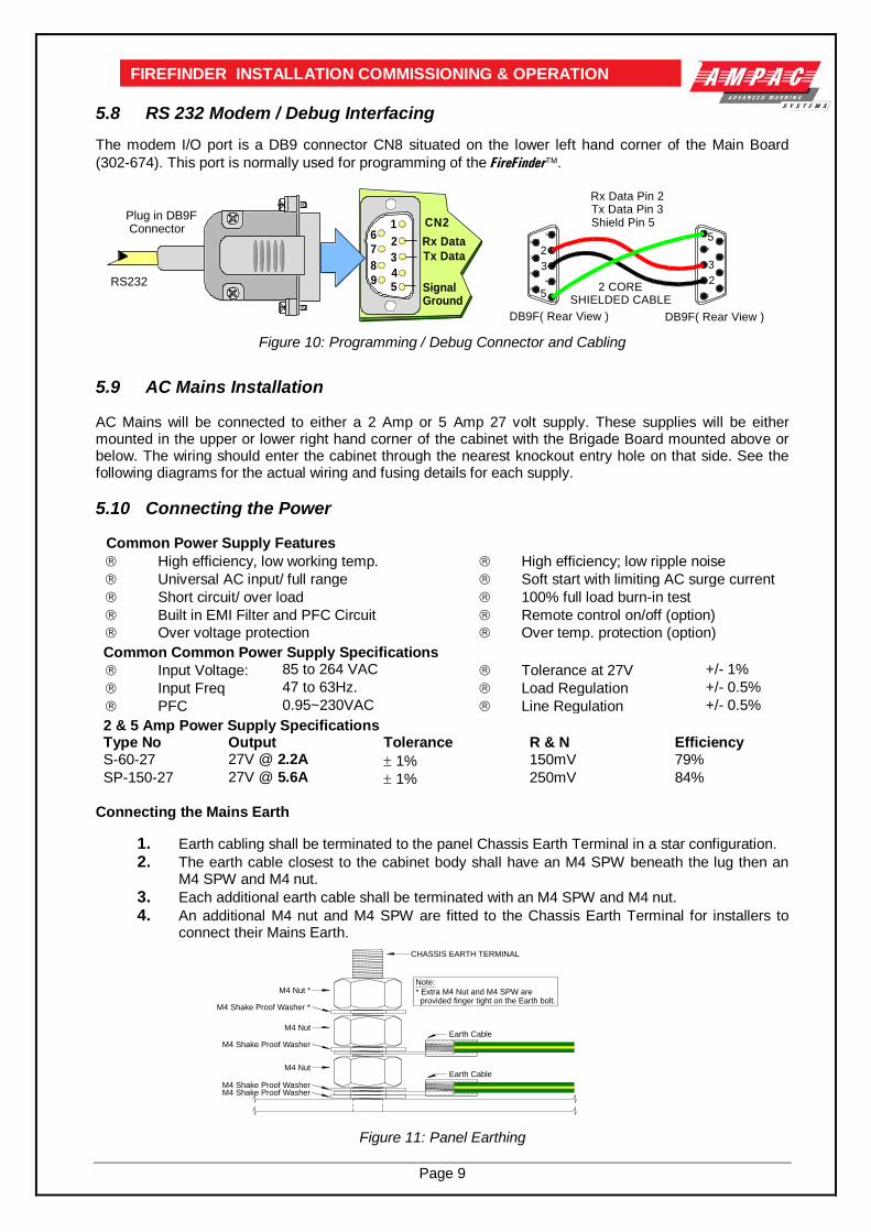
5.8 RS 232 Modem / Debug Interfacing
The modem I/O port is a DB9 connector CN8 situated on the lower left hand corner of the Main Board
(302-674). This port is normally used for programming of the FireFinder.
16
2
3
45
7
8
9
Tx Data
Rx Data
SignalGround
CN2Plug in DB9F Connector
RS232
1
2
34
5
6
7
8
9
DB9F( Rear View )
2 CORESHIELDED CABLE
DB9F( Rear View )
1
2
3
4
5
6
7
8
9
Rx Data Pin 2Tx Data Pin 3Shield Pin 5
Figure 10: Programming / Debug Connector and Cabling
5.9 AC Mains Installation AC Mains will be connected to either a 2 Amp or 5 Amp 27 volt supply. These supplies will be either mounted in the upper or lower right hand corner of the cabinet with the Brigade Board mounted above or below. The wiring should enter the cabinet through the nearest knockout entry hole on that side. See the following diagrams for the actual wiring and fusing details for each supply.
5.10 Connecting the Power
Common Power Supply Features
High efficiency, low working temp. High efficiency; low ripple noise
Universal AC input/ full range Soft start with limiting AC surge current
Short circuit/ over load 100% full load burn-in test
Built in EMI Filter and PFC Circuit Remote control on/off (option)
Over voltage protection Over temp. protection (option)
Common Common Power Supply Specifications
Input Voltage: 85 to 264 VAC Tolerance at 27V +/- 1%
Input Freq 47 to 63Hz. Load Regulation +/- 0.5%
PFC 0.95~230VAC Line Regulation +/- 0.5%
2 & 5 Amp Power Supply Specifications
Type No Output Tolerance R & N Efficiency S-60-27 27V @ 2.2A 1% 150mV 79%
SP-150-27 27V @ 5.6A 1% 250mV 84%
Connecting the Mains Earth
1. Earth cabling shall be terminated to the panel Chassis Earth Terminal in a star configuration.
2. The earth cable closest to the cabinet body shall have an M4 SPW beneath the lug then an M4 SPW and M4 nut.
3. Each additional earth cable shall be terminated with an M4 SPW and M4 nut.
4. An additional M4 nut and M4 SPW are fitted to the Chassis Earth Terminal for installers to connect their Mains Earth.
Figure 11: Panel Earthing
M4 Shake Proof Washer
M4 Shake Proof WasherM4 Shake Proof Washer
CHASSIS EARTH TERMINAL
M4 Nut
Earth Cable
Earth Cable
M4 Nut
M4 Shake Proof Washer *
M4 Nut *Note:
* Extra M4 Nut and M4 SPW are provided finger tight on the Earth bolt.

Page 10
FIREFINDER INSTALLATION COMMISSIONING & OPERATION Connecting the Mains to the 2 Amp Power Supply Terminate the mains power to the 240 VAC switch terminal block as shown below.
Figure 12: Mains Power Connection to the 2 Amp Power Supply
CONNECTING THE MAINS to the 5 AMP POWER SUPPLY
Figure 13: Mains Power Connection to the 5 Amp Power Supply
POWER SWITCH(LOOKING AT REAR)
MAINS CORD BROWN (ACTIVE)
BLUE (NEUTRAL)
BROWN (ACTIVE)
LED1
TO EARTH STUD
DC 27V TO PANEL
EARTH (GREEN)
L(AC)N(AC)GNDV-V+
V ADJ
TO EARTH STUD
DC 27V TO PANEL
EARTH (GREEN)
V ADJ
L(AC) N(AC) -V -V +V +V +(AC)
BLACK
RED
POWER SWITCH(LOOKING AT REAR)
MAINS CORD BROWN (ACTIVE)
BLUE (NEUTRAL)
Fuse is under this cover
NOTE: FUSE Rating 1 Amp 3AG Slow Blow Mains cable should be no
less than 0.75mm
NOTE: FUSE Rating 2 Amp 3AG Slow Blow Mains cable should be no
less than 0.75mm
Page 11
FIREFINDER INSTALLATION COMMISSIONING & OPERATION
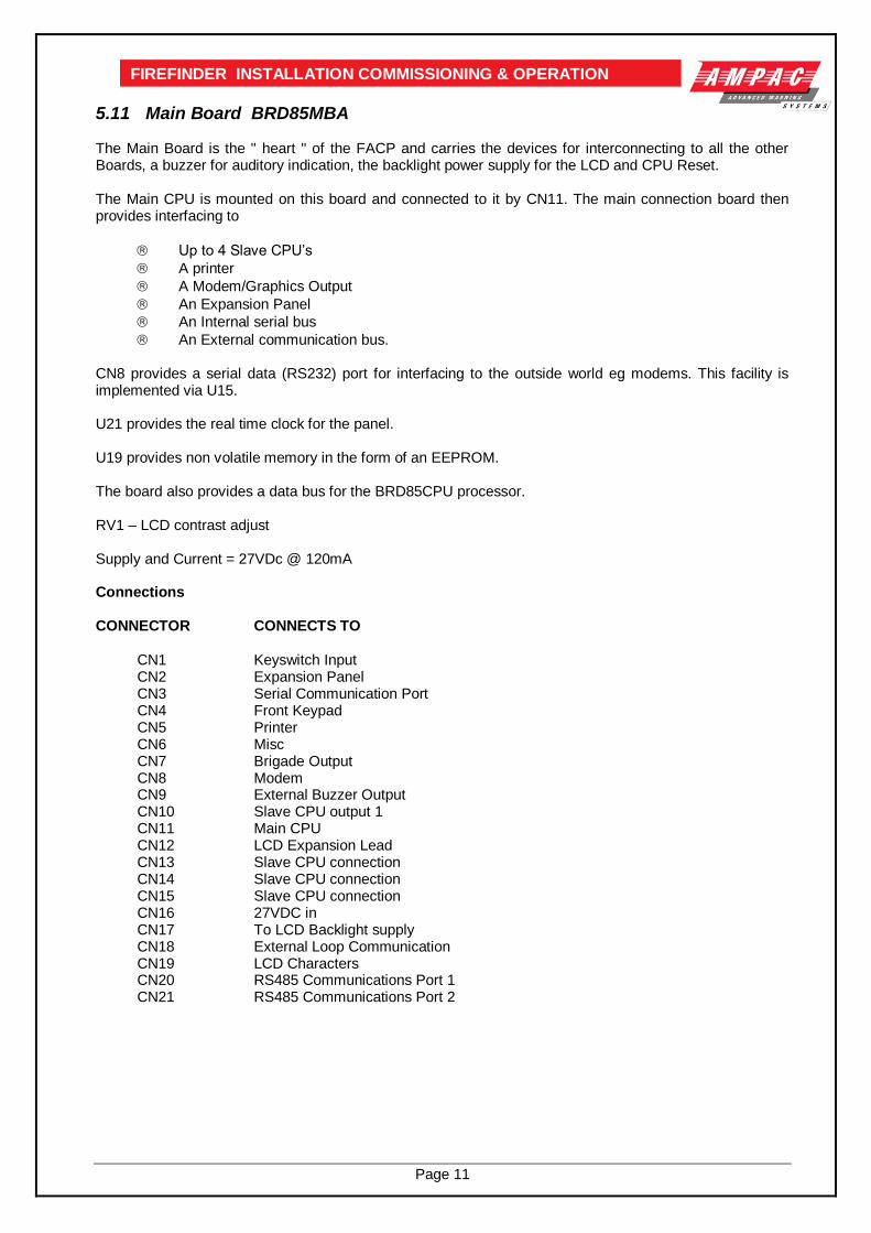
5.11 Main Board BRD85MBA The Main Board is the " heart " of the FACP and carries the devices for interconnecting to all the other Boards, a buzzer for auditory indication, the backlight power supply for the LCD and CPU Reset. The Main CPU is mounted on this board and connected to it by CN11. The main connection board then provides interfacing to
Up to 4 Slave CPU’s
A printer
A Modem/Graphics Output
An Expansion Panel
An Internal serial bus
An External communication bus. CN8 provides a serial data (RS232) port for interfacing to the outside world eg modems. This facility is implemented via U15. U21 provides the real time clock for the panel. U19 provides non volatile memory in the form of an EEPROM. The board also provides a data bus for the BRD85CPU processor. RV1 – LCD contrast adjust Supply and Current = 27VDc @ 120mA Connections CONNECTOR CONNECTS TO
CN1 Keyswitch Input CN2 Expansion Panel CN3 Serial Communication Port CN4 Front Keypad CN5 Printer CN6 Misc CN7 Brigade Output CN8 Modem CN9 External Buzzer Output CN10 Slave CPU output 1 CN11 Main CPU CN12 LCD Expansion Lead CN13 Slave CPU connection CN14 Slave CPU connection CN15 Slave CPU connection CN16 27VDC in CN17 To LCD Backlight supply CN18 External Loop Communication CN19 LCD Characters CN20 RS485 Communications Port 1 CN21 RS485 Communications Port 2

Page 12
FIREFINDER INSTALLATION COMMISSIONING & OPERATION
RV1
CN8CN6
SW1
CN11
CN16
CN9
CN14
SW3
CN15CN13
CN17LCBACKLIGHT
SLAVE CPU2
FRONT PANEL
EXPANSION LEDS
MODEMDEBUGI/O PORT
27V IN
RESET
INTERNAL PRINTER
TO BRIGADEPSU MONITOR
BOARD ORSOUNDER BOARD
30
2-6
74
E
NODEADDRESS
1
+
BRD85MBA TOP OVERLAY
CONTROL INDICATOR CARD
CN21
CN20
+ -
SLAVE CPU3SLAVE CPU4
CN2 CN3 CN4
BZ1
NOT USED
CN5
CN7
CN10
ON BOARDSLAVE CPUCABLES TO
LOOP TERMINATION
BOARD
RS485COMMS
EXPANSION BOARDFOR 4 SLAVE CPU's
RS485 COMMS
CN1
O O OO O OO O OO O OO O OO O OO O OO O OO O OO O OO O OO O OO O OO O OO O OO O OO O OO O OO O OO O OO O OO O OO O OO O OO O OO O OO O OO O OO O OO O OO O OO O O
a b c
ON
1
2
3
4
5
6
7
8
CN18
NETWORKING
LCD CONTRASTADJUST
Figure 14: Main Board Layout with no Main CPU or Slave CPU’s
5.12 Front Panel Board 302 -690 The Front Panel Board provides the buttons used to control the FACP as well as all LED indications. All LED’s are surface mounted and the buttons are embedded within the board. The LCD is viewed / protected by a clear perspex screen.
Figure 15: Front Panel Board
D15
D1
D16
U4
D21
U2
D8
D9
D11
D12
D13
D14
D10
D2
D3
D4
D6
D7
D5
CN1 Cables to CN4on the Main Board
U5
U3
U6
D22
D23
D24
U1
API 690 JAN 2002
LCD Cut - out
Page 13
FIREFINDER INSTALLATION COMMISSIONING & OPERATION
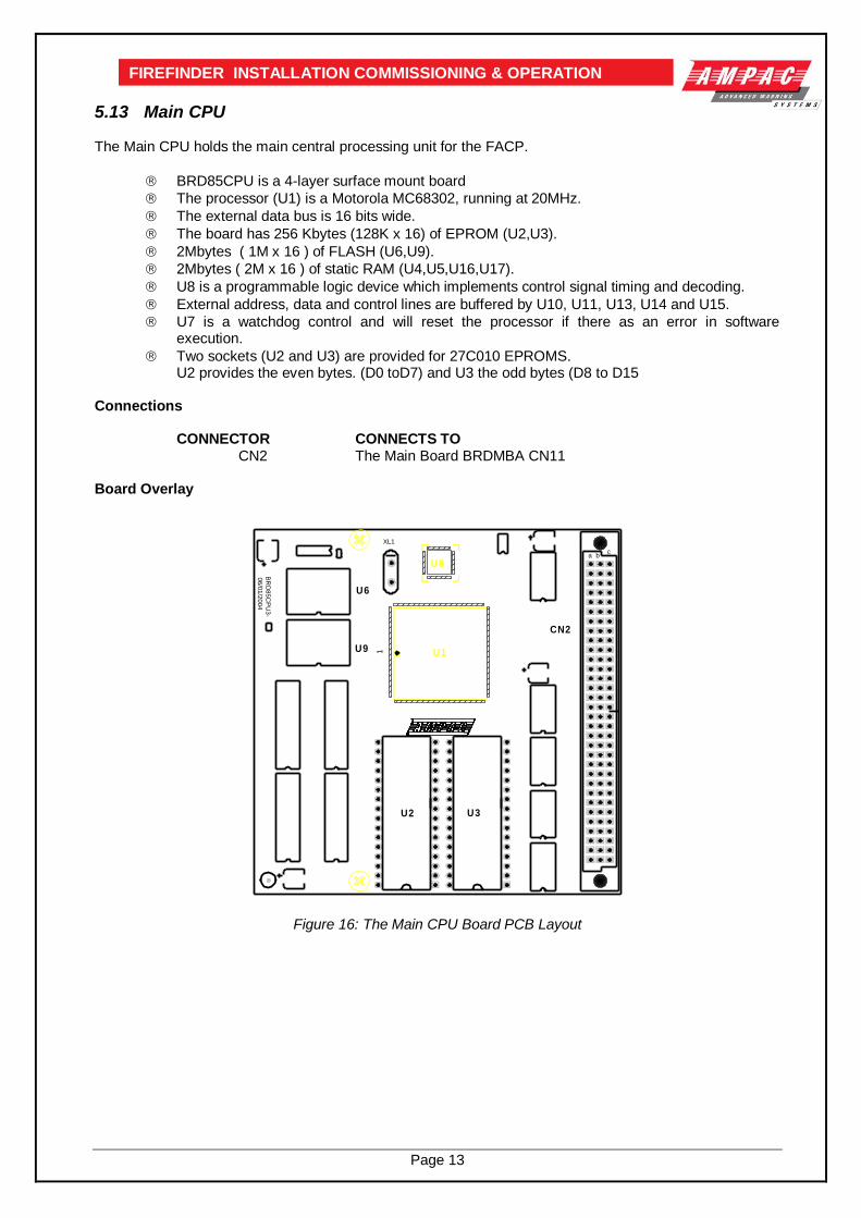
5.13 Main CPU The Main CPU holds the main central processing unit for the FACP.
BRD85CPU is a 4-layer surface mount board
The processor (U1) is a Motorola MC68302, running at 20MHz.
The external data bus is 16 bits wide.
The board has 256 Kbytes (128K x 16) of EPROM (U2,U3).
2Mbytes ( 1M x 16 ) of FLASH (U6,U9).
2Mbytes ( 2M x 16 ) of static RAM (U4,U5,U16,U17).
U8 is a programmable logic device which implements control signal timing and decoding.
External address, data and control lines are buffered by U10, U11, U13, U14 and U15.
U7 is a watchdog control and will reset the processor if there as an error in software execution.
Two sockets (U2 and U3) are provided for 27C010 EPROMS. U2 provides the even bytes. (D0 toD7) and U3 the odd bytes (D8 to D15
Connections
CONNECTOR CONNECTS TO CN2 The Main Board BRDMBA CN11
Board Overlay
U1
U8
U6
1
XL1
CN2
a bc
U9
U2 U3
BR
D8
5C
PU
3-
06
/01
/20
04
Figure 16: The Main CPU Board PCB Layout

Page 14
FIREFINDER INSTALLATION COMMISSIONING & OPERATION
5.14 Slave CPU The Slave CPU (Central Processing Unit) provides the interfacing signals and I/O’s required to allow the FACP to connect / communicate to a variety of termination boards. A single chip micro controller U1 controls all operations of the FACP Slave CPU. This device contains the control program within Read Only Memory (ROM). Communication to the main system is via an eight bit bi-directional bus (CN1). Integrated circuits U5, U3 and U7 provide buffering and data latches that allow data flow between the Main and Slave CPU’s. The buffers hold one output byte and two input bytes. CN1 provides the interconnection to the Termination Board. Within CN1 are ten analogue input lines, two input/output lines, two current loop outputs (RS422) and one current loop input (RS422). All analogue inputs are de-coupled then fed to an eight-bit analogue to digital converter (ADC) U4. The data from the ADC is sent via a serial peripheral interface to the micro controller U8. The current loop inputs and outputs are used to provide various signals according to the board connected. The signals provided can be serial peripheral interface clock and data signals or full duplex asynchronous data and a timing output. U6 provides the signal multiplexing and buffering required to switch between different functions. Automatic Termination Board Sensing A unique feature of the Slave CPU is its ability to automatically sense the type of board it is connected to without the user having to configure the board to suit. Board sensing is done by measuring the voltage on analogue input ten (CN1-10), denoted Type Voltage. Each termination board provides a unique predefined voltage. After the Slave CPU has determined the board type the Slave CPU will set the appropriate operating conditions, signal the Main CPU of the installed type and wait for the Main CPU to inform the Slave to begin executing the program. Connections
Connector Connects to CN1 302-670, 302-671 and 302-672 CN2 Main Connection Board (BRD85MBA)
Figure 17: Slave CPU Board
U9TLC542
U4U3
U8
U2
U6 U7U5
X1
CN21
1 1
1
1
302-696
CN1U1
Ma
in B
oa
rd

Page 15
FIREFINDER INSTALLATION COMMISSIONING & OPERATION
5.15 Brigade / PSU Monitor Board The Brigade / PSU Monitor Board (302 – 673), referred to in the following as the Brigade Board, monitors and controls the power supply, battery charging, monitored / un-monitored inputs, outputs and the 7 relay outputs. Providing the Power supply has adequate capacity monitored Bell/Sounder O/P’s are capable of driving 2 X 2Amp circuits. Each circuit, terminated in a bell/sounder or not, requires a 10K EOL resistor to give a system normal indication. If either circuit is open or shorted, the panel buzzer will sound and a Sounder Fault will be indicated on the Panel. Monitoring is achieved using a small reverse polarity current. For this reason it is necessary to ensure that all alarm devices are fitted with a series diode (1N4004 recommended) and correct polarity is observed for both the output and the sounders they are connected to. Relay outputs marked NO, C and NC are voltage free relay contacts. Outputs marked +ve and -ve are fitted with resistors (10k) to allow the circuit to be monitored. If these outputs are un-used they must be
terminated at the terminal block or turned off in ConfigManger. For all outputs combined, total output current is 2A ( if 2.5A power supply is being used ). Once all the field devices are installed and the wiring has been correctly terminated the FireFinder™ is ready to turn on. Turn the Mains power on, and connect the batteries observing correct polarity. The green power on LED should be illuminated. OUTPUT RATINGS
TB Function Type of Output Fuse Relay
3 Bell 1 2 Amp Fused F2 RL 1
Bell 2 2 Amp Fused F3 RL 1
4 Plant (Aux) Monitored 1 Amp Fused F4
Plant (Aux) Non-Monitored 1 Amp Voltage Free Contacts RL2
5 Warn Sys (Evac) Monitored 1 Amp Fused F5
Warn Sys (Evac) Un-Monitored 1 Amp Voltage Free Contacts RL3
6 Fault Monitored 1 Amp Fused F6
Fault Non-Monitored 1 Amp Voltage Free Contacts RL 4
7 Isolate 1 Amp Voltage Free Contacts RL6
8 Alarm 1 Amp Voltage Free Contacts RL 5
9 Valve Monitor 1 Amp Voltage Free Contacts RL 8
10 Batt Fail 1 Amp Voltage Free Contacts RL 7
1 Battery Output Thermistor Protected
2 Aux Power Output 1 Amp Fused Not Monitored F7
Aux Power Output 1 Amp Fused Not Monitored F8
Fuse Information 1. All fuses are of the Glass M205 style.
2. F1 is 6.3A 3. Voltage Free contacts are rated at 1A @ 30V
Back EMF Protection
Inductive loads fitted to the Brigade PSU Monitor Board MUST be fitted with “Flyback”
diodes at the load for back EMF protection.
Transient Protection
Recognised transient line protection methodologies at the FACP and the load MUST also be
considered when connecting any control devices to the outputs be they in close or remote proximity to the FACP.

Page 16
FIREFINDER INSTALLATION COMMISSIONING & OPERATION
Figure 18: Brigade / PSU Monitor Board Layout Note: When connecting to the Brigade PSU Monitor board transient and “Flyback” (Back EMF) protection methodologies Must be applied.
Aux Power
O/P
Isolate Relay
Alarm Relay
NO
C N
C+
-
+
-N
O C
NC
Batt Fail Relay
Valve Mon Relay
+ IN - + BAT -
30
2-6
73
0
MA
Y 9
8
+
-
RL4
TB2
CN5
TB1
RL7
RL5
RL6
CN6
TB6
CN1
CN2
RL8
TB11
6.3A
CN3
TB8
TB7
TB10
TB9
M1
5
///NO
NCC RL1
RL2
+
-
Fault NO
C N
C+
-
NO
C N
CN
O C
NC
NO
C N
C
To CN7 of the Main Controller Board
- +
--
+ -
- +
-
CN1, 2, 3 SuppliesRegulated +27VDC to Internal Boards
+27VDCfrom PSU
Voltage Free ContactsNC = Normally ClosedC = CommonNO = Normally Open
TB4
TB5
Monitored
Un-monitored
Monitored EOLRequired
EOLRequired
Monitored EOLRequired
Monitored EOLRequired
C
NC
NO
NO
C N
C
Un-monitored
Un-monitored
Bell 1
Bell 2
++
-
TB3
Bell
EOL10KOhms
Warning System
Auxiliary
Door Switch
DBAMCP
Battery 2
12VoltsBattery 1 12 Volts
+-
-+
-
Signal GeneratingDevice SDG Type II
F2 2A
F4 1A
F5 1A
F8 1A
F7 1A
F6
1A
F3 2A
Bell 1
Bell 2
Aux Mon.
Warning Sys. Mon
Aux Power Out
Fault Out Mon.
+27 Volt In
F1
Warning System TOAlert / Evac Amp
MonitoredEOL Required
Page 17
FIREFINDER INSTALLATION COMMISSIONING & OPERATION
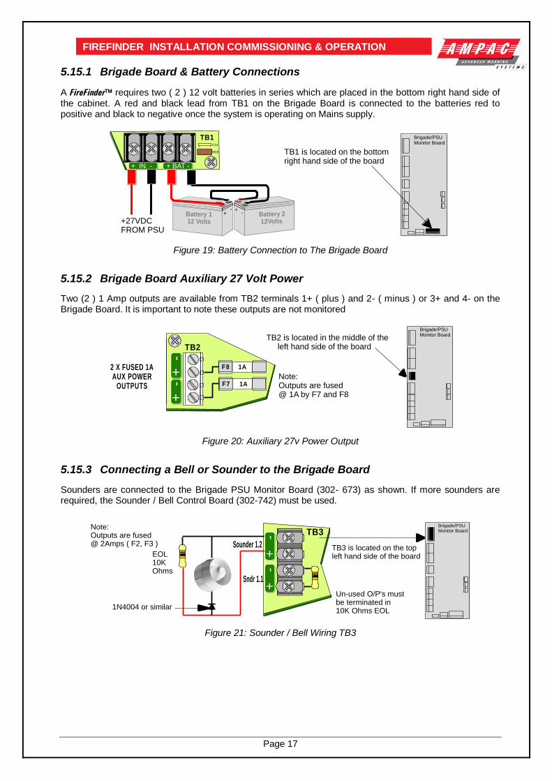
5.15.1 Brigade Board & Battery Connections
A FireFinder requires two ( 2 ) 12 volt batteries in series which are placed in the bottom right hand side of the cabinet. A red and black lead from TB1 on the Brigade Board is connected to the batteries red to positive and black to negative once the system is operating on Mains supply.
+27VDCFROM PSU
TB1 is located on the bottomright hand side of the board
Brigade/PSU Monitor Board
Battery 2 12Volts
Battery 1 12 Volts
+-
-+
TB1C14
M20
+ BAT -+ IN -
Figure 19: Battery Connection to The Brigade Board
5.15.2 Brigade Board Auxiliary 27 Volt Power
Two (2 ) 1 Amp outputs are available from TB2 terminals 1+ ( plus ) and 2- ( minus ) or 3+ and 4- on the Brigade Board. It is important to note these outputs are not monitored
2 X FUSED 1AAUX POWER
OUTPUTS
TB2 is located in the middle of the left hand side of the board
Brigade/PSU Monitor Board
TB2
+
- 1A
1A
+
-
F8
F7Note:Outputs are fused@ 1A by F7 and F8
Figure 20: Auxiliary 27v Power Output
5.15.3 Connecting a Bell or Sounder to the Brigade Board
Sounders are connected to the Brigade PSU Monitor Board (302- 673) as shown. If more sounders are required, the Sounder / Bell Control Board (302-742) must be used.
Sndr 1.1
Sounder 1.2
TB3Brigade/PSU Monitor Board
EOL10KOhms
Un-used O/P's mustbe terminated in10K Ohms EOL
+ -
+ -
TB3 is located on the topleft hand side of the board
1N4004 or similar
Note:Outputs are fused@ 2Amps ( F2, F3 )
Figure 21: Sounder / Bell Wiring TB3

Page 18
FIREFINDER INSTALLATION COMMISSIONING & OPERATION
Au
xilia
ry
Sounder 2
TB5
TB4
Brigade/PSU Monitor Board
SounderEOL10KOhms
EOL10KOhms
NO
C N
C+
-
NO
C N
C+
-
TB4 & 5 are located on the top left hand side of the board
Note: 1. NO C NC are 1A voltage free contacts
2. + / - are monitored / fused 1A outputsUn-used O/P's must be terminated in10K Ohms EOL
Warn
ing
Sy
ste
m
Figure 22: Sounder / Bell Wiring TB5
5.15.4 Connecting the Alert / Evacuation Amplifier
Overview: The EVAC50W24V is a 100VRMS-Line Amplifier whose features include; the generation of the ‘Alert’ and ‘Evacuation’ tones with verbal messages as specified by
NZS4512:2003. driving up to 50W (with a 27.4VDC supply) into 100V PA loud speakers, the 100Vrms output line is overload and short-circuit protected and is monitored by the amplifier
circuit with the status transmitted to the panel. control through a set of signal (BELL) inputs. Multiple amplifiers can be daisy chained together
(BELL IN – BELL OUT) or individually zone operated if connected to a Bell Sounder Control Board. the ability to be powered directly from the panel battery or from a separate DC source. low current draw - when not active (100V line monitoring only) the amplifier draws less than 35mA. an optional microphone input board is available which can be used for public address (PA) or ‘Fire
Microphone’ operation. Specifications:
Board Dimensions: 97mm x 150mm. Height 50mm from bottom of PCB
Mounting Dimensions: 89mm x 130mm.
Operating Voltage: 20 - 29Vdc, nominal 27.4Vdc
Quiescent Current: 30mA RS485: <30mA @ 27.4Vdc
Operating Current: 2.5A @ 27.4Vdc nominal with 50W load.
Power Output: 50W @ 100V line: 27.4Vdc supply – overload and short-circuit protected
Tone: Evacuation tone and verbal message, compliant to NZS4512:2003. Programmed using the LED base address dials and program-jumpers.
Monitoring: Fully monitored for open, short circuit or overload (10kΩ, 1W EOL resistor)
1200Hz
500Hz
VoiceMessage
3sec.
VoiceMessage
3sec.
0.0
sec.
3.7
5sec.
4.0
sec.
7.7
5sec.
8.0
sec.
11.7
5sec.
12.0
sec.
15.7
5sec.
16
.5sec.
19
.5sec.
20
.5sec.
23
.5sec.
24
.0sec.
3.75
sec0.25sec
Figure 23: NZS4512 Evacuation Signal with Voice Messaging

Page 19
FIREFINDER INSTALLATION COMMISSIONING & OPERATION Operation: The Amplifier is connected to the FACP Warning System output as shown in the connection diagrams. The ‘+’ and ‘-’ terminals are connected to the corresponding ‘+’ and ‘-’ terminals on the amplifier. In the ‘Normal’ state, the FACP monitors the 100V line 10K 1W EOL resistor by applying an inverted voltage to the amplifier input terminals. In this state the amplifier connects the 10K 1W EOL line resistor to the Bell input. A 10K 1W EOL resistor must be used across the 100Vrms line for correct operation of the amplifier monitoring circuit. In the ‘Alarm’ state, the FACP reverses the bell voltage causing the amplifier to activate and output a repeating ‘Evacuation Tone followed by a voiced Evacuation Message’ onto the 100Vrms loudspeaker circuit. The amplifier is NOT monitored during the ‘Alarm’ state. If the amplifier output is overloaded, or the supply voltage becomes ‘Off-Normal’, the amplifier will signal a defect by turning on the Defect/Fault LED (refer Table 1).
Fault LED ON LED Defect Description
Off Off Amplifier inactive
Off Steady Amplifier active
Steady Flashing Supply Voltage below 10V or above 15V
Flashing Steady Amplifier output is overloaded
Table 1 The 100Vrms Line may have a maximum of three spurs. For these configurations an EOL resistor of the appropriate value must be installed at the end of each spur. (See Table 2).
Number Of Spurs Number Of Spurs
1 1 x 10K 1W
2 1 x 22K 1W on each spur
3 1 x 33K 1W on each spur
Table 2
Installation Criteria
Capacitively-coupled 100Vrms PA Speakers must be used with the 50W Amplifier. The capacitor must be bipolar and able to withstand 250V peak line voltage. The value should be around 1uF per watt of power for each speaker.
100Vrms speaker wiring must be separated from ELV (Extra Low Voltage) wiring.
Loading of the 100Vrms line must not exceed 50W.
An excessive load will cause the Amplifier to current limit and shutdown. The symptoms for this may be interruptions in the audio output and two or more amplifiers broadcasting out of synchronization.
Loading of the bell output must not exceed the maximum fuse (FACP Bell Circuit Fuse 4 = 2A) or relay (50W Amplifier Line Relay maximum contact current = 3A) rating.
100VRMS SPEAKERS
DECOUPLING CAPACITORS
10K OHM2W EOLRESISTOR
BELL IN FROMTB5 - WARNING
SYSTEMOF THE
BRIGADE PSUMONITOR BRD
+
-
+-
Screen
+ -
10KOHMEOL
BELL OUT
Figure 24: Basic Connection Diagram

Page 20
FIREFINDER INSTALLATION COMMISSIONING & OPERATION
SPURRED 100VRMS SPEAKERS
DECOUPLING CAPACITORS
22K OHM1W EOLRESISTOR
+
-
+-
Screen
22K OHM1W EOLRESISTOR
+ -10KOHMEOL
BELL IN FROMTB5 - WARNING
SYSTEMOF THE
BRIGADE PSUMONITOR BRD
BELL OUT
Figure 25: Spurred Speaker Wiring Diagram
5.15.5 Brigade Board Relay Output Connections
Brigade/PSU Monitor Board
TB10 TB9 TB8 TB7 TB6
TB10 to TB6 are located on thelower left hand side of the boardC
NC
NO
1A Un-monitoredVoltage Free Conacts:NO: Normally OpenNC: Normally ClosedC: Common
NO C NCNO C NCNO C NCNO C NCNO C NC NO C NC NO C NC NO C NC
NO C NC+ -
FAULTISOLATEALARMVALVE MONBATT FAIL
M23 M27 M26 M24
+ - = 1A monitored output and must be terminated in EOL
EOL10KOhms
Note 2:
Note 1:
Figure 26: Relay Outputs
5.15.6 Signal Generating Device The SGD (302-678) interfaces the FACP Brigade / PSU Monitoring Board to a line transmitter to facilitate monitoring by a Fire Brigade or monitoring service. Interconnection is from the SGD (CN2) to the Brigade / PSU Monitoring Board CN6. Test of the FACP and SDG monitoring should be carried out in accordance with the LTX SDG Input Interface Specifications. To comply with the latest standards the software has been upgraded to Version 3.
K2
BZ1
+
CN1
X1
K1
U3
U4
TB1
SW
2
SW
1
302 678
250mA
DOORSWITCH
CN2FIRE
SYSTEM
All links off = 16
SGDADDRESS
POLL
ISOLATE
DEFECT
FIRE
NORMAL
2
4
1
8
TESTISOLATE
NORMAL NORMAL
B
-
+
A
IITypeSGD
AMPAC
Cabling to LTXInterface&12Volt Supply
F1
TB1
B
-+
A
POLL
ISOLATE
DEFECT
FIRE
NORMAL
K1
2
4
1
8AddressingExample Set to 5
TO CN6 OF THE BRIGADEPSU MONITORING BOARD
NOT USED
Figure 27: SGD Layout

Page 21
FIREFINDER INSTALLATION COMMISSIONING & OPERATION
6 Compatible FireFinderTM Modules
Numbers in Italic are Fast Fit Kit Part Numbers
Module / Board ................................................... Part Number Max Number
Slave CPU .................................................................. (302-6690) 8 per Controller # 1 ( 159-0007 )
Conventional Zone Board ........................................... (302-6710) 8 per Controller ( 159-0005 )
Apollo Loop Termination Board ................................... (302-7350) 8 per Controller ( 159-0003 )
16/16 Input / Output Board .......................................... (302-6720) 8 per Slave CPU ( 159-0008 )
8 Way Relay Board ..................................................... (302-6760) 16 per Slave CPU ( 159-0012 )
16 Way Input Board .................................................... (302-6770) 8 per Slave CPU ( 159-0010 )
Serial Relay Board ...................................................... (302-7320) 8 per Controller ( 159-0072 )
Fan Control Module .................................................... (302-6800) 8 per Slave CPU ( 159-0020 )
Fan Termination Board…………………………………….(302-7820 Depends on 302-6800 ( 159-0078 )
Expansion Board ........................................................ (302-6880) 1 per Controller ( 159-0045 )
Brigade / Power Supply Unit Monitor Board ................ (302-6730) 1 per Panel
Alert Evac Amplifier ..................................................... ( TBA ) Configuration dependant
Signal Generating Device ............................................ 302-6780 1 per Panel
Valve Display Module ................................................. (302-7160) 8 per Slave CPU ( 159-0048 )
Pump Display Module ................................................. (302-7170) 10 per Slave CPU ( 159-0047 )
Zone Display .............................................................. (302-7000) 4 per Slave CPU ( 159-0018 )
Sounder/Bell Controller Board 1A per Circuit................ (302-7420) 8 per Controller ( 159-0071 )
Sounder/Bell Controller Board 4Volt free, 4x1Amp ....... (302-7421) 8 per Controller (159-0069)
Printer ......................................................................... (TPUP-AT) 1 per Controller
Agent Release Module / Agent Termination Board ....... (BRD25ARB-A) 8 per Controller
Local Control Station (IP40) ......................................... (BRD25ARB-B) 4 per Termination Board
Expansion Board ........................................................ (302-6880) 1 per Controller
Expansion Controller ................................................... (SP16X: 159-0077) 3 per Node ( Rack: 159-0067 )
Compatible Networking Devices
Expansion Controller ................................................... (302-6740) 3 per Node ( 159-0077 )
Network Interface Card ............................................... (302-7240) 1 per Controller ( 159-0053 )
Controller Interface Card ............................................. (302-7250) 1 per Controller ( 159-0054 )
LCD Repeater ( Main Processor Board ) ...................... (302-7200) Note # 2 ( 159-0044 )
LCD Repeater ( Keypad ) ............................................ (302-7210) Note # 2
LED Mimic Board ........................................................ (302-7150) 31 per Controller
Note # 1 : This comprises 4 on the Main Controller and 4 on the Expansion Board.
Note # 2 : Depends on the configuration and the number of Panels in the System.

Page 22
FIREFINDER INSTALLATION COMMISSIONING & OPERATION
6.1 Conventional Zone Board The 302-671 Conventional Zone Board provides the interface between the external conventional devices
and the FireFinder™. Conventional zones are connected from TB4 to TB1 on the 302-671 16 Zone Conventional Board.
Figure 28: 16 Zone Conventional Board
AZF Parameters
Maximum Line Voltage: The maximum line voltage is limited to the system voltage. With a nominal battery voltage of 27V, system voltage and therefore open circuit voltage would be approximately 26.4V.
U5
U6
U8
RN7
M15
M14
0V
M1
M2 C2
M3
M4 C4
M5
M6 C7
M7
M8 C10
M9
M10 C13
M11
M12 C15
M13
C18
M16 C20
C27
M17
M18
C29
M19
M20
C31
M21
M22
M23
C34M24
M25
C37M26
M27
M28 C39
M29
M30 C42
M31
M32
5V
CN1
U2
R1
R7R4
R5
U1
R8
D16
U11
CN2
RN
12
RN
6R
N3
C5
C1
ZD16
ZD15
ZD14
ZD13
ZD12
ZD11
ZD10
ZD9
R55
R52
R49
R46
R43
R40
R36
ZD8
ZD7
ZD6
ZD4
ZD5
ZD2
ZD3
ZD1
R27
R24
R21
R15
R12
R9
R57
R54
R51
R48
R45
R42
R38
R53
R50
R47
R44
R41
R37
R32
R35
R30
R28
R26
R25
R23
R22
R20
R17
R19
R16
R14
R13
R11
R10
R3
R6
TB4
D9
D1
0D
11
D1
2D
13
D1
4
D1
5U
4
D8
D1
D2
D3
D4
D5
D6
D7
C8
C4
5
R3
3
C25
R2
9
C21
RN8
U7
C4
0
U1
0
C3
6
U9
RN11
RN10
C3
2
C1
2
RN5
RN4
RN14RN13
RN
9
C1
7
C3
C6
C9
C1
4C
16
C1
9C
23
C2
8C
30
C3
3C
35
C3
8C
41
C4
3
Q2
Q1
Q3
Q4
Q5
Q6
Q7
Q8
Q9
Q10
Q11
Q12
Q13
Q14
Q15
Q16
C11R18
R2
U3
C46R56
RN2RN1
C47
C2
4
R31TB3
TB2
TB1
C48
+1
6-
+1
-
ZO
NE
+2
-
ZO
NE
+3
-
ZO
NE
+4
-
ZO
NE
+5
-
ZO
NE
+6
-
ZO
NE
+7
-
ZO
NE
+8
-
ZO
NE
- +
-
PO
WE
R
ZO
NE
ZO
NE
+1
5-
ZO
NE
+1
4-
ZO
NE
+1
3-
ZO
NE
+1
2-
ZO
NE
+1
1-
ZO
NE
+1
0-
ZO
NE
+9
-
302-671B
+
+
27/2/01
To 27VDC Regulated Output ( Brigade PSU Monitor Board )
3K3EOL
3K3EOL
3K3EOL
3K3EOL
3K3EOL
3K3EOL
3K3EOL
3K3EOL
3K3EOL
3K3EOL
3K3EOL
3K3EOL
3K3EOL
3K3EOL
3K3EOL
To SlaveCPU
1
2
SCREWCAPS
MOUNTINGHOLES
WIRE IN WIRE OUT
WIRE IN
TERMINATING METHOD
AMPAC27.0
LED
MEASURE LINE VOLTAGE
WIRE OUT
UP TO 40 DETECTORS CAN BECONNECTED TO EACH CIRCUIT
NOTE:
AMPAC MANUAL
CALL POINT
IN +
+ O
UT
IN -
- OU
T
SERIES65 DETECTOR
L1 In
-R
L2
Earth
L1 Out
AMPAC HEATDETECTOR
3K3EOL

Page 23
FIREFINDER INSTALLATION COMMISSIONING & OPERATION
6.2 Apollo Loop Termination Board The 302-735 Addressable Loop termination board provides the interface between the external addressable
devices and the FireFinder™. Each board provides termination’s for two loops. One slave CPU is required per loop. Addressable loops are connected from TB1 to TB2 on the 302-735 Apollo Loop Termination Board. Note: Apollo devices L2 is +ve (positive), L1 is -ve (negative) Connect your XP95 / DISCOVERY loop to the panel as shown.
AMPAC strongly recommend that the LoopManager test set is used to check that the Apollo loop has been
correctly installed and commissioned before connecting it to the FireFinder.™. Loop Parameters
126 Apollo
250mA Current Max
S/C protected
Figure 29: Loop Termination Board
C4
9
A B A B
BABA
TX1
R73
Q8
R81
R80R79
R78
C41
R77
R76R75
R74
R45
R44
R43
Q24Q23
Q22
Q19
C48
C4
7
C46
C45
C44
C43C42C34
U11CN2
D8
C38C40C39
C37
D14
CN3 CN1
R30
ZD10
Q9
Q7
C12
R4
8R
64
R6
3
C29
C10
C13
C3 C6
R46
C15
U1
Q1
0
Q11
R28R29
ZD2
R27
R4
D7
D5
D3
R12
R13
R14
R22
R25
C2
C1
R21
C7 U2
R10
R6
ZD1R24
R9
R8
C11 U3
R19
R20
R11
R7
R57R56R55
R26
C14R42 R41R18
R69 R66
R61R47
R53 R54
U7
R32R31
R35
U6
U8
U9
R34
R33
R37
C22
Q1
2
R23
R51
R17
R6
8
R6
5R
60
R5
8
R52D6
Q1
5
C24
Q1
4
C25
Q1
6
Q1
3
D4
C21
M4
M3
TB2
M1
M2
RN
2
ZD6C20
ZD8C27
C31 ZD5
C19ZD7
C26ZD9
C30
R15
C17
ZD3
C18ZD4
R16
D2
Q2
Q1
Q3
Q6
Q4
Q5
R3
R5
0
R49
C9
C5
C8
C4
R2
R1
R5
M11
M12
C36
R5
9
R6
2
R6
7
R7
0
M10
M9
C35
RN
3
C33
M8
M7
TB1 M5
C32
M6
RV1
C28
D9D10
D11
D1
2
D13
Q1
7
Q18
Q21 TH2
TH
3
ZD11
CN4
C23
R38
R40
R71R72
D1R39
Q20
R36
C16
U4
U5
C50
+
+
+
+
+
+
302-7350AUG 2000
L2+ L1- L2+ L1- L2+ L1- L2+ L1-
26V ADJ
POWER
SP488
3A
302-7350
TO 27VDCREGULATEDO/P OFBRIGADE PSUMONITORBOARD
T0 SLAVECPU CN1
T0 SLAVECPU CN1
LOOP 1 ADDRESSABLE DEVICES
LOOP 2 ADDRESSABLE DEVICES
LOOP NORMAL
LED A monitoring each Loop is ON
LED A & B ON indicates a fault on the Loop ( S/C, O/C ) and the Loop is being monitored in both directions
LOOP IN FAULT
F1: 3AMP M205 27V INTO DC TO DC CONVERTOR
R +L1
L2-R
L1
L2-R
L1
L2-R
R +
R +
Wiring Shown Above is for aXP95 Circuit
-+-
F1
L1
L1
L1
L2
L2
L2
Page 24
FIREFINDER INSTALLATION COMMISSIONING & OPERATION
6.3 16/16 Input / Output Board The 302-672 input / output board provides the interface between the Slave CPU module, 8 way relay board and the 16 Opto input board. The input / output board is connected to the slave CPU via CN1. A maximum of 8 input / output boards can be daisy chained together. This is dependant on the panel configuration.
Figure 30: Input Output Board
6.4 8 Way Relay Board Relay Outputs: The 8 Way Relay Board comes in two versions. The 302-6760 is fitted with eight 1A voltage free contacts while the 302-6761 is fitted with eight 5A relays voltage free contacts.
Figure 31: 8 Way Relay Board
TO 8 WAY RELAY BOARD TO 16 WAY OPTO-INPUT BOARD
TO CONTROL IN OF NEXT INPUT / OUTPUT BOARDOR FAN CONTROL MODULE(MAXIMUM OF 8 MODULESPER CPU)
CN6, CN7 +27V In / Out
TO CN1 OFTHE SLAVECPU
CN1CONTROL IN
CN2CONTROL OUT
OUTPUTS 1-8 OUTPUTS 9-16 INPUTS 1-16
302-672PO
WE
R
CTRL
I/P 1-16O/P 9-16
IN
O/P 1-8
CTRLOUT
C8
TP
IC6
B5
95
U2
R3
74
HC
16
5
U7
CN7
CN6
0V +V
CN2
C4
C3
+5V
+C9
C11
CN3CN4CN5C6
RN1
U9
CN1
C7 RN2
R7
D1
C1
R1
R2
C2
74
HC
165
U8
TP
IC6
B5
95
U1
R11
R1
2
SP490
U4
SP490
U3
SP490
U5C14
+
C10
74
HC
14
U6
C5
C12-+-
-+-
CN1
R1
MOV2 MOV3
MOV17
TB2TB1
R3
D3
MOV1
D1 D2 D4 D5 D6 D7
MOV4
MOV5
MOV6
MOV7
MOV8
MOV9
MOV10
MOV11
MOV12
MOV13
MOV14
MOV15
MOV16
R8R7R6R5R4R2
D8
7/9
7
O/P 1N/CCN/0
30
2-6
76
x
TO CN4 OR CN5302-672
O/P 2N/0 C N/C
O/P 3N/0 C N/C
O/P 4N/0 C N/C
O/P 5N/0 C N/C
O/P 6N/0 C N/C
O/P 7N/0 C N/C
O/P 8N/0 C N/C
N/C
N/O
C
N/O
C
N/C
///
N/O
C
N/C
///N/O
C
N/C
///
N/O
C
N/C
///
N/O
C
N/C
///
N/O
C
N/C
///
N/O
C
N/C
///
N/O
C
N/C
///
N/O
C
N/C
///
RL2RL1 RL3 RL4 RL5 RL6 RL7 RL8
Relays:1 - 8 are 1A9 - 16 are 5Acontacts
RL9 RL10 RL11 RL13RL12 RL15RL14 RL16
RL9
RL1
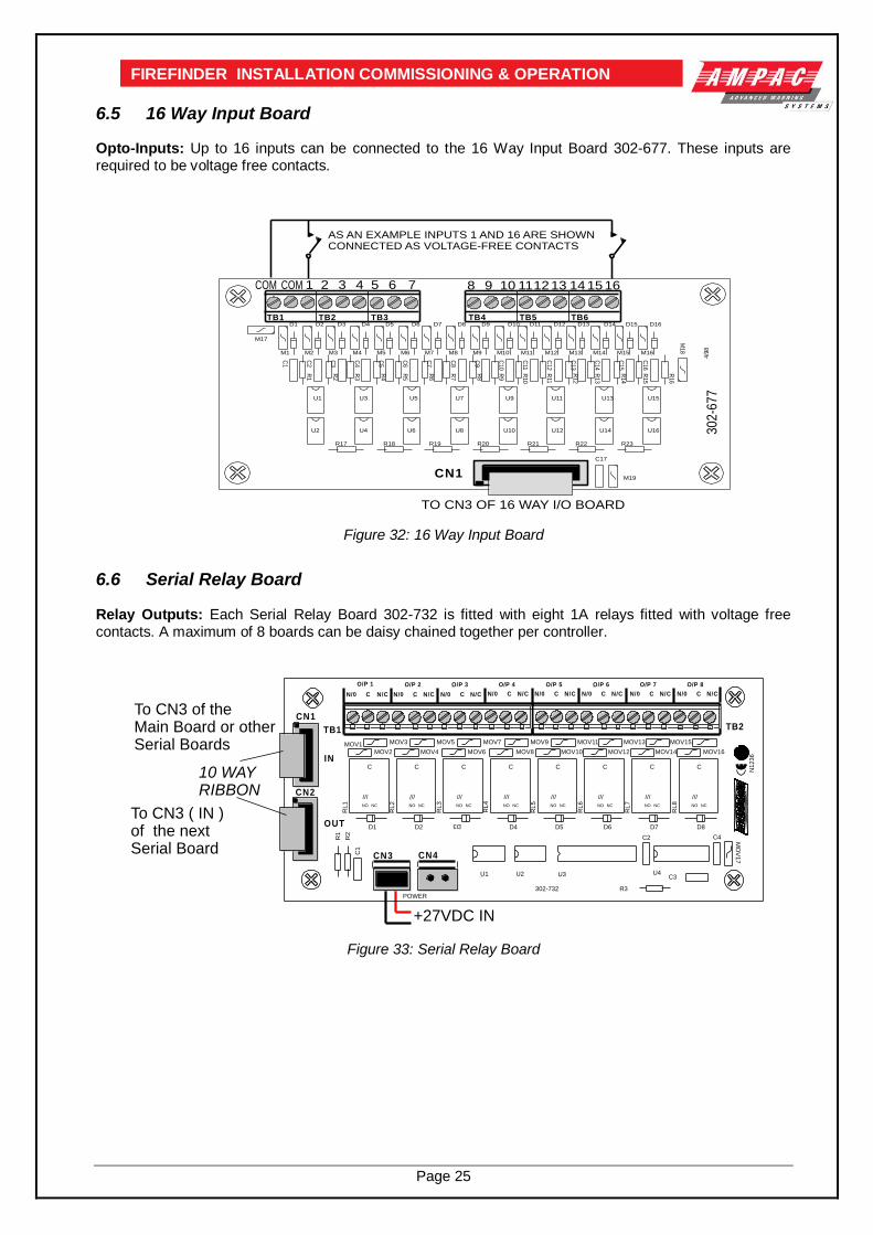
Page 25
FIREFINDER INSTALLATION COMMISSIONING & OPERATION
6.5 16 Way Input Board Opto-Inputs: Up to 16 inputs can be connected to the 16 Way Input Board 302-677. These inputs are required to be voltage free contacts.
Figure 32: 16 Way Input Board
6.6 Serial Relay Board Relay Outputs: Each Serial Relay Board 302-732 is fitted with eight 1A relays fitted with voltage free contacts. A maximum of 8 boards can be daisy chained together per controller.
Figure 33: Serial Relay Board
4/9
8
1 2COM COM 3 4 5 6 7 8 9 10 111213 141516
M19
C17
M18
M17
CN1
TB2 TB3 TB4 TB5 TB6D1
M2 M3 M4
D4
C2
C3
C4
U4
U1
U2
M5 M6 M7 M8 M9 M10 M11 M12 M13 M14 M15 M16
D5 D6 D7 D8 D9 D10 D11 D12 D13 D14 D15 D16
C5
C6
C7
C8
C9
C10
C11
C12
C13
C15
C16
R7
R10
U5 U7
U8
U9
U10
U11
U12
U13
U14
U15
U16
C14
D2 D3
R6
R8
R12
R14
R1
R2
R3
R9
R11
R13
R15
R16
R17 R19 R21 R23R22R20R18
U6
U3
TB1
C1
R4
R5
M1
30
2-6
77
TO CN3 OF 16 WAY I/O BOARD
AS AN EXAMPLE INPUTS 1 AND 16 ARE SHOWNCONNECTED AS VOLTAGE-FREE CONTACTS
N/0
10 WAY RIBBON
+27VDC IN
C3
CN4
R3
C1
R2
R1
U4
C4C2
U1 U2
CN3
CN1
RL
1
MOV1 MOV3
MO
V1
7
TB2TB1
D3
RL
8
RL
7
RL
6
RL
5
RL
4
RL
3
RL
2
MOV2
D1 D2 D4 D5 D6 D7
MOV4
MOV5
MOV6
MOV7
MOV8
MOV9
MOV10
MOV11
MOV12
MOV13
MOV14
MOV15
MOV16
D8
CN2
U3
N1
23
6
POWER
N/0 C N/C
O/P 1
C
O/P 2
N/C N/0 C
O/P 3
N/C N/0 C
O/P 4
N/C N/0 C
O/P 5
N/C N/0 C
O/P 6
N/C N/0 C
O/P 7
N/C N/0 C
O/P 8
N/C
302-732
IN
OUT
C
NCNO
///
C
NCNO
///
C
NCNO
///
C
NCNO
///
C
NCNO
///
C
NCNO
///
C
NCNO
///
C
NCNO
///
To CN3 of theMain Board or otherSerial Boards
To CN3 ( IN )of the nextSerial Board

Page 26
FIREFINDER INSTALLATION COMMISSIONING & OPERATION
6.7 Fire Fan Module BRD25FCB The Fire Fan Module has four ( 4 ) separate fan controls each having an On, Auto and Off function switch and a set of three (3) monitoring LED’s. The LED’s indicate the status of the equipment eg. Run, Fault or Stop. The two ( 2 ) arrow head keys are used to step up and / or down through the three ( 3 ) conditions. A slip in label can also be inserted into the hinged cover for identification purposes.
Note#: As per AS 1668.1 1991, Clause 14.17.4 lettering on any of the slip in labels must be at least 5mm in height.
Slip In
Label
Module & PCB Securing Tabs( Top & Bottom )
PCBClear Plastic Clip In Label
Clip OnPlastic Surround ( Push down here and pullout to remove and insert labels )
WINDOWS
WINDOWS
FOR SLIP
IN LABELS
Lettering on slip inlabels must be atleast 5mm in height.
K2 Termination Link
In OutAddress SwitchSet to 1
1 2
3 4
ONCN1
CN2
CN1: Communications & 27V IN from CN2 off the previousFront Panel Card or CN20 on the Main Control Board
CN2: Communications & 27V OUT to Next Front Panel Card.If Unsed the Termination Link Must be Inserted.
Top Module &PCB Securing Clips
Bottom Module &PCB Securing Clips
Figure 34: Fire Fan Module Front Panel Figure 35: Fire Fan Module PCB Layout
6.8 Fan Termination Board BRD25FTB The Fan Termination Board interfaces between the Fire Fan Module and the plant/equipment it controls via the 24 volt 250mA Start, Stop, current limited, relay outputs and monitor inputs. Programmable monitoring of the field equipment is achieved using 0 volts as an input level to indicate run, fault and stop conditions of that equipment. Monitoring is programmed in the Function Menu for a 3, 4 or 5 Wire Start / Stop, Run, Fault, Stop & Common functions. The inputs are protected by way of resetable transorbs and resistive / capacitive networks. Connectors CN5 Is used for factory programming only and may not be available on all boards. Terminal Blocks TB2 – 5 Are used to connect the fan control and monitoring wiring to the board.
SW1
TB4TB3TB2
LK1
TB5
EOL Termination
0V
+2
7V
PO
WE
R
Address SW
FAN 1FAN 1STOP COMSTOPFLTRUN
FAN 2STOP COMSTOPFLTRUNSTART
FAN 3FAN 3STOP COMSTOPFLTRUNSTART
FAN 4COMSTOPFLTRUNSTART
FAN 4STOPSTART
FAN 2
CN1
CN2
CN3 CN4
RS485 Control in from CN2 of PreviousBoard or CN21 of the Main Control Board
RS485 Control Out to Next Board or Link 1 EOL is Applied
27V In from the Brigade Broard or CN4 of the Previous Board
27V Out to Next Board if Applicable
1 2 3 4
O N
STOP
COM
STOP
FLT
RUN
START
TB 2, 3, 4 or 5
Cabling from FACPto Plant / Equipment
1 2 3 4 5 6
FAN CONTROLSOLID STATE ORRELAY INTERFACE
FAN MONITORING
0VINPUTS 1, 2 & 3+24V O/Ps
RUN
STOP, START, RUN = 3 WIRE
STOP, START, RUN,STOP = 4 WIRE
STOP, START, RUN, STOP,FAULT = 5 WIRE
Figure 36: Fan Termination Board Layout and Typical I/O Wiring
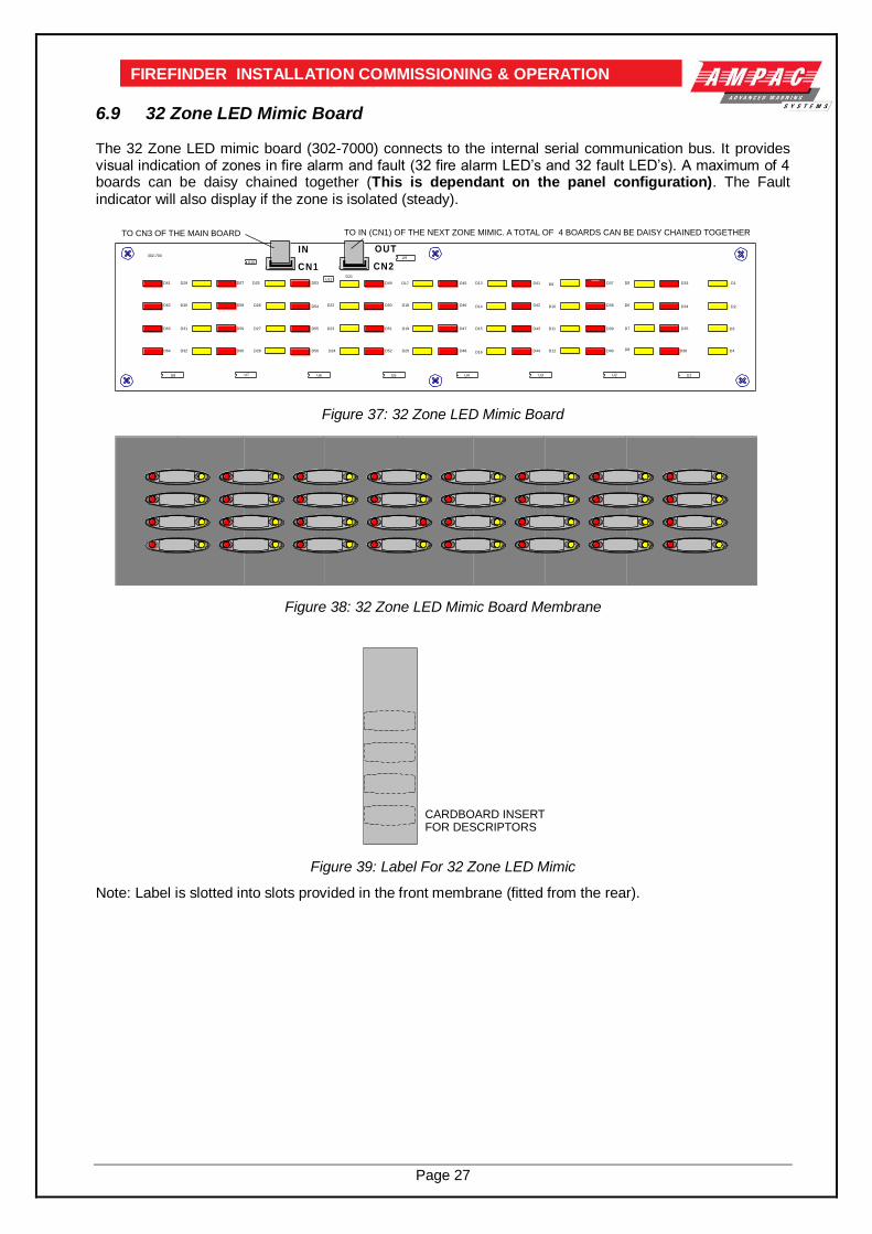
Page 27
FIREFINDER INSTALLATION COMMISSIONING & OPERATION
6.9 32 Zone LED Mimic Board The 32 Zone LED mimic board (302-7000) connects to the internal serial communication bus. It provides visual indication of zones in fire alarm and fault (32 fire alarm LED’s and 32 fault LED’s). A maximum of 4 boards can be daisy chained together (This is dependant on the panel configuration). The Fault indicator will also display if the zone is isolated (steady).
OUTIN302-700
U9U10
D5
D6
D7
D8
D33
D34
D35
D36
D1
D2
D3
D4
U1
D9
D10
D11
D12
D37
D38
D39
D40
U2
D13
D14
D15
D16
D41
D42
D43
D44
U3
D17
D18
D19
D20 D48
D47
D46
D45
U4
D21
D22
D23
D24
D49
D50
D51
D52
U5
D26
D27
D28
D25 D53
D54
D55
D56
U6U7
D61
D62
D63
D64
D29
D30
D31
D32
D57
D59
D58
D60
U8
1 CN21 CN1U11
TO CN3 OF THE MAIN BOARD TO IN (CN1) OF THE NEXT ZONE MIMIC. A TOTAL OF 4 BOARDS CAN BE DAISY CHAINED TOGETHER
Figure 37: 32 Zone LED Mimic Board
Figure 38: 32 Zone LED Mimic Board Membrane
Figure 39: Label For 32 Zone LED Mimic
Note: Label is slotted into slots provided in the front membrane (fitted from the rear).
TEXT
TEXT
TEXT
TEXT CARDBOARD INSERT FOR DESCRIPTORS

Page 28
FIREFINDER INSTALLATION COMMISSIONING & OPERATION
6.10 Valve Display Module The Valve Display Module (302-716) connects to the internal serial communication bus. It provides visual indication of the Valve status (16 x Valve open, 16 x Valve closed). A maximum of 8 modules can be daisy chained together per CPU. This is dependant on the panel configuration.
Figure 40: Valve Indicator Board
Figure 41: Valve Indicator Membrane
CLOSEDOPEN
CLOSEDOPEN
CLOSEDOPEN
CLOSEDOPEN
CLOSED
CLOSED
CLOSEDOPEN
CLOSEDOPEN
CLOSEDOPEN
CLOSEDOPEN
CLOSEDOPEN
CLOSEDOPEN
CLOSEDOPEN
CLOSEDOPEN
OPEN
CLOSEDOPEN
OPEN
CLOSEDOPEN
SLIP INDESIGNATORLABEL
SLIP INDESIGNATORLABEL
TO CN3 (IN) OF THE NEXT BOARD
TO CN3 OF THE MAINBOARD
(CN1 or CN2)+27VDC I/P
+
+
302-716
R36
C12
C2
R32
R31
R15
U2
C6
R22
R21
R16
TP3
CN2
CN1
C11
D33
R35
U8
TP1
TP2
C10
CN3
CN4
U6U7
C8C9
U5
R33
R34
C7
C5
C4
U3
U4
U1
C3
C1
D18 D17
D20 D19
D22 D21
D24 D23
D26 D25
D28 D27
D30 D29
D32 D31
R17
R18
R19
R20
R23
R24
R25
R26
R27
R28
R29
R30
D2 D1
D4 D3
R2
R1
D6 D5
R3R4
R5
D8 D7
R6
R7
D10 D9
R8
R9
D12D11
R10
R11
D14
D13
R12
R13
D16 D15
R14
- + -
- + -

Page 29
FIREFINDER INSTALLATION COMMISSIONING & OPERATION
6.11 Pump Display Module The Pump Display Module connects (302-717) to the internal serial communication bus. It provides visual indication of the Pump status (8 x Supply Healthy, 8 x Pump Running, 8 x Pump Fault). A maximum of 10 modules can be daisy chained together per CPU. This is dependant on the panel configuration.
Figure 42: Pump Display Board
Figure 43: Pump Display Membrane
Note: Labels are fitted to the above two items as per the 302-7000
PUMP FAULT
PUMP RUNNING
SUPPLY HEALTHY
PUMP FAULT
PUMP RUNNING
SUPPLY HEALTHY
PUMP FAULT
PUMP RUNNING
SUPPLY HEALTHY
PUMP FAULT
PUMP RUNNING
SUPPLY HEALTHY
PUMP FAULT
PUMP RUNNING
SUPPLY HEALTHY
PUMP FAULT
PUMP RUNNING
SUPPLY HEALTHY
PUMP FAULT
PUMP RUNNING
SUPPLY HEALTHY
PUMP FAULT
PUMP RUNNING
SUPPLY HEALTHY
Slip inDesignatorLabel
Slip inDesignatorLabel
TO CN3 OF THE MAIN BOARD TO CN3 (IN) OF THE NEXT BOARD
+
+
302-717
R36
C12
CN4
R23
C4
C6
TP3
CN2
CN1
C11
D33
R35
U8
TP1
TP2C10
CN3U6U7
C8C9
U5
R33
R34
C7
C5
D2
D1
D3
D4
D5
D6
D7
D8
D9
D10
D11
D12
D23
D24
D22
D21
D18
D17
D16
D15
D14
D13
R2
R1
R3
R4
R5
R6
R7
R8
R9
R10R11
R12
R15
R16
R17
R18
R19
R20
R21
R22
R24
R13R14
U3
U2
U1
C1
C3
C2
D20
D19
(CN1or CN2)+27VDC I/P
- + -
- + -

Page 30
FIREFINDER INSTALLATION COMMISSIONING & OPERATION
6.12 Sounder / Bell Controller Board The 302-742 (8 way Bell Monitor Board) options allow a larger number of bells / sounders to be connected
to the FireFinder™ system and /or Alert / Evac Amplifiers to be configured for zoned operation. The 302-742 is built in two versions: 1. 302-7420: All outputs are monitored and provide 1 Amp per circuit. 2. 302-7421: The first 4 circuits are Voltage free contacts, the second 4 are as per the 302-7420. The Sounder/ Bell monitor board connects to the serial peripheral interface (SPI) bus. This is the same bus that connects to the Brigade PSU Monitor Board. A maximum of 8 boards can be daisy chained together.
= Shaded Components are Not Fitted to 302-7421 SounderMonitor Brd. Volt-Free Terminals but are Fitted to the 302-7420
10K EOL
10KEOL
10K EOL
This area will bemarked with the correct Version Number
RL7
TB5
C27
X1
U9
U7
U4U3
U2
TB4
TB3
TB2
TB7
TB6
R40
R39
R38
R37
R36
R35
R34
R33
R32
R31
R30
R29
R23
R22
R21
R20
R13
R12
R11
R10
D35
D34
D33
D32
D31
D30
D29
D28
D1
C26
C25
C24
C5C4
D5
D4
D3
D2
D9
D7
D6
RL6
RL1
RL2
RL4
D8
RL5
TB1
RL3
RL8
U1
302-742
NO
+N
C-
CN
O+
NC
-C
NO
+N
C-
CN
O+
NC
-C
+V
E-V
E+
VE
-VE
+V
E-V
E+
VE
-VE
0V+27V
AT
90
S8
53
5-8
JC
OUTIN
1A
1A
1A
1A
1A
1A
1A
1A
LK2
LK1
D10
NORMAL
Note:If the O/P was configuredas a monitored O/P, asbelow, NO is the +ve legwhile NC is the -ve leg.
Sounder
10
K E
OL
Bell
To CN7 of theMain Controller
To IN (CN1) of nextSounder Monitor Board or Output Brigade BoardCN5
To the AUX PowerO/P TB2 of the O/P Brigade Board
EOL Resistors are not requiredif the O/P is configured for VoltFree Contacts NO, NC, & C
All Fuses are 1A M205 Style
10
K E
OL
CN1 CN2
F2
F1
F3
F4
F6
F7
F5
F8
EVAC50W24V
BellIN
100VLineOUT
BellOUT
10KEOL
Figure 44: Sounder / Bell Controller Board
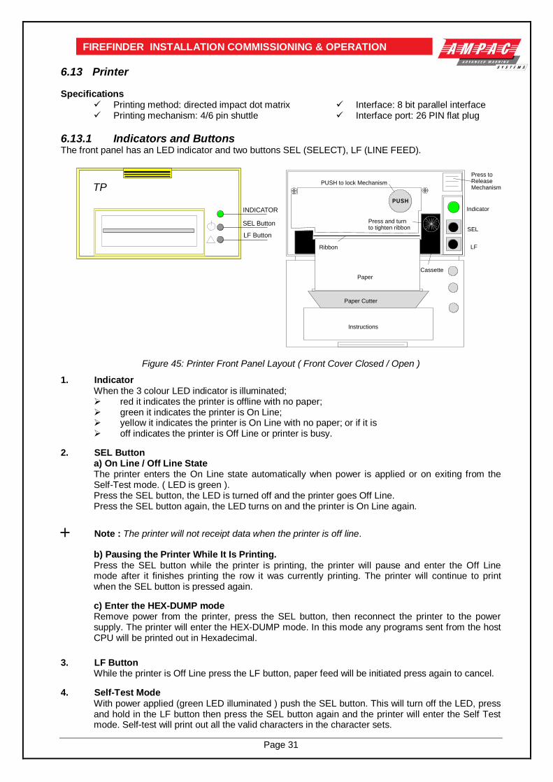
Page 31
FIREFINDER INSTALLATION COMMISSIONING & OPERATION
6.13 Printer Specifications
Printing method: directed impact dot matrix Interface: 8 bit parallel interface Printing mechanism: 4/6 pin shuttle Interface port: 26 PIN flat plug
6.13.1 Indicators and Buttons The front panel has an LED indicator and two buttons SEL (SELECT), LF (LINE FEED).
Figure 45: Printer Front Panel Layout ( Front Cover Closed / Open )
1. Indicator When the 3 colour LED indicator is illuminated; red it indicates the printer is offline with no paper; green it indicates the printer is On Line; yellow it indicates the printer is On Line with no paper; or if it is off indicates the printer is Off Line or printer is busy.
2. SEL Button a) On Line / Off Line State The printer enters the On Line state automatically when power is applied or on exiting from the Self-Test mode. ( LED is green ). Press the SEL button, the LED is turned off and the printer goes Off Line. Press the SEL button again, the LED turns on and the printer is On Line again.
Note : The printer will not receipt data when the printer is off line.
b) Pausing the Printer While It Is Printing. Press the SEL button while the printer is printing, the printer will pause and enter the Off Line mode after it finishes printing the row it was currently printing. The printer will continue to print when the SEL button is pressed again.
c) Enter the HEX-DUMP mode Remove power from the printer, press the SEL button, then reconnect the printer to the power supply. The printer will enter the HEX-DUMP mode. In this mode any programs sent from the host CPU will be printed out in Hexadecimal.
3. LF Button While the printer is Off Line press the LF button, paper feed will be initiated press again to cancel.
4. Self-Test Mode With power applied (green LED illuminated ) push the SEL button. This will turn off the LED, press and hold in the LF button then press the SEL button again and the printer will enter the Self Test mode. Self-test will print out all the valid characters in the character sets.
SEL Button
LF Button
TP
INDICATOR
Paper
Paper Cutter
Instructions
Indicator
SEL
LF
Cassette
Ribbon
Press and turnto tighten ribbon
Press toReleaseMechanism
PUSH to lock Mechanism
PUSH

Page 32
FIREFINDER INSTALLATION COMMISSIONING & OPERATION 5) Exit the Self-Test Mode:
a) After printing out the complete Self-Test list the printer will exit the mode automatically; or b) Press the SEL button and the printer will immediately exit the Self-Test mode.
6.13.2 Maintenance
Installing The Ribbon Cassette The printer has a factory loaded ink ribbon cassette.
Ribbon Replacement;
Push back the mechanism head and lock it, close the cover of the printer and reconnect the power. Loading the Paper Roll
1. Disconnect the power, unlock and open the front cover. 2. Push down on the mechanism release button in the top right corner to release the head. 3. Lift the mechanism as shown below.
Hinges
LED
PushButtons
Paper
PUSH
MechanismReleaseButton
Note:Front DoorRemoved
Ink RibbonCassette
Note:Front DoorRemoved
Replacement Paper Roll
Figure 47: Head Mechanism Rotation and Paper Roll Removal / Insertion
4. Take out the empty paper roll and roller 5. Put the new paper roll onto the paper roller and replace as shown above. 6. Connect to the power supply. 7. Press the SEL button to take the printer Off Line, ( LED is off ). 8. Press the LF button, ( paper feed ). 9. Feed the edge of the paper into the mechanism and allow it to feed through. 10. Once it established the paper is feeding through the head mechanism correctly press the
SEL button to stop the paper feed. 11. Return the printer head to its original position. 12. Pushing on the affixed label PUSH the head mechanism back into position. 13. Close the front cover.
Hinges
LED
PushButtons
Paper
PUSH
MechanismReleaseButton
Front DoorLocking Tab
Paper Cutter
Figure 46: Front Panel
1. Remove the power from the printer. 2. Unlock the front cover by pushing down on the tab at the top
of the front panel. 3. Push the mechanism release button in the top right corner to
release the print head. 4. To remove the ribbon cassette gently pull out the left end
then the right.
Replace the cassette by putting the right end of the new cassette slightly onto the drive axle then gentle pushing the left end into the clips.
The left end of the cassette can only be pressed in after the right end has been correctly seated onto the drive axle. If alignment is difficult it may be necessary to turn the knob on the cassette slightly. Now check that the ribbon is tight across the face of the cassette, that is on the inside of the cassette and across the paper. Turn the knob clockwise again if the ribbon is on the outside of the cassette.

Page 33
FIREFINDER INSTALLATION COMMISSIONING & OPERATION
Note #1: Press only on the PUSH label to return the head mechanism back into
position.
Note #2 :The above instructions are graphically displayed on the inside of the front cover..
6.13.3 Printer Connections and Jumpering
Mounted on the back of the printer mechanism is the PCB that carries the; 1. connectors for interconnection to the Main Board, 2. jumper links required to set the programmed print modes; and 3. Printer 5 volt DC Power Supply.
R
5
R6
C14
R7 C15
C16
C18C8C17 C7
C19
C21
D2
R9
T1
R8
C3
C20
C4
C22
R11J7J6R10
C5T2
C13
C12
X1
J1
J3
R1C9 R2
D1 R4
R3
C1
C2
U1
U2
U3
U4
U6
C6
U7
U8
T4
T3
U5
J2
UP-ATHZPVER:CC 2002.1
J1 OPEN ESC Command Set CLOSE UP Command SetJ2 OPEN ASCII Char Mode CLOSE Chinese ModeJ3 OPEN UP-A Direction CLOSE UP-T Direction
U9
Connector to Print HeadConnector toFront PanelLED & Switches
Connector to Main Board 5V Power Supply
+ -
J7 Select 12X12 (Pins 1/2) or 15X16 (Pins 2/3) Chinese Characters
Figure 48: PCB Layout
Jumper Settings
Designator Jumper State Function
J1 NOT Inserted Selects ESC Commands Inserted Selects UP Commands
J2 Set as Default
NOT Inserted Selects ASCII Character Printing Mode
Inserted Selects Chinese Character Printing Mode
J3 NOT Inserted Select Printing by Contrary Direction Inserted Select printing in the Normal Direction
J7 Set as Default
Insert the Shorting Clip Between Pins 1 and 2
Selects the 12 X 12 Font
Insert the Shorting Clip Between Pin 2 and 3
Selects the 15 X 16 Font
6.13.4 Printer 5 Volt Power Supply ( 302-713 ) 27 volts DC is taken from Brigade / PSU Monitor Board and fed to CN 2 of the 5volt Printer Power Supply Board. It is this board that drops this voltage from 27volts to 5volts for use by the Printer.
CN2
0.5A
F1
HY1
CN1
5V
OU
T
AP
I-713
IN: 18 -36VDCOUT: 5VDC
- IN
+
OU
T +
OU
T -
TO PRINTER+
-+
--
27VDC IN
Figure 49: Printer Power Supply Board Layout

Page 34
FIREFINDER INSTALLATION COMMISSIONING & OPERATION
7 Agent Release Control Agent Release control consists of a Agent Release Module, Termination Board and an optional Local Control Station.
7.1 Operation Introduction The Agent Release Module and Termination Board communicate with the FACP via the RS485 multi-drop bus. The Local Control Station communicates only with the Termination Board via a separate RS485 bus. Up to 4 Local Control Stations can be connected to one termination board. Agent discharge operates in two modes – automatic and manual. The manual mode is selected by pressing the Inhibit switch on any Local Control Station. To indicate the system is in manual the Inhibit LED will be illuminated. Pressing Inhibit again will toggle or return the mode to automatic and extinguish the Inhibit LED. The “ Agent Released ” Pressure Switch ( PSW ) is wired to the PSW input on the Termination Board and is used to confirm that the agent has been released. The circuitry involved in this process can be configured to accept a normally open contact, normally closed contact, or is ignored and is selected via FACP on-site programming. Manual Mode When the system is in manual mode, then;
The Local Control Station Inhibit indicator is lit at the FACP and all Local Control Station’s.
The buzzer at all Local Control Stations will sound until the inhibit is released.
The System Inoperative output is turned on.
The Automatic discharge sequences are prevented from starting. If a discharge sequence was underway when the inhibit switch was activated the discharge sequence is aborted and the sequence is reset. To manually discharge the agent the “ Lock Off Valve “ must be open and the Manual Release switch on the Local Control Station pressed. The manual discharge sequence is;
Manual Activation indicator is lit on the FACP and Local Control Station.
The FACP activates its brigade alarm output.
Stage 1 outputs are switched to +24VDC. [ FIRE ALARM sign illuminated, aural alarm sounds ].
Stage 2 outputs are switched to +24VDC. [ FIRE ALARM, EVACUATE & DO NOT ENTER signs illuminated, aural alarm sounds ].
The optional pre-release start delay is activated ( Selected via FACP on-site programming ), time out and an ON Interlock signal will then operate the selected release circuitry.
The Agent Discharge LED on the Agent Release Module and Local Control Station will illuminate when the Pressure Switch input on the Termination Board is activated.
Activate gas-fired output.
Note: The Interlock Input can be defaulted to the on position by placing a 10K EOL termination
resistor across the terminals TB2. 7 / 8 of the Agent Release Module and Local Control Station. Auto Mode Automatic discharge is when one or two zones going into alarm initiate the agent discharge sequence.
Note: A “manual release” can still be initiated in “auto mode” but the LCS “Inhibit” control WILL
NOT inhibit / abort the agent release sequence.

Page 35
FIREFINDER INSTALLATION COMMISSIONING & OPERATION Single Zone Activation, the following discharge sequence is executed;
Automatic Activation LED is illuminated on the Agent Release Module and Local Control Station.
Stage 1 outputs are switched to +24VDC. [FIRE ALARM sign illuminated, aural alarm sounds].
Stage 2 outputs are switched to +24VDC. [ FIRE ALARM, EVACUATE & DO NOT ENTER signs illuminated, aural alarm sounds ].
Optional pre-release delay is started ( Selected via FACP on-site programming ).
The delay times out and if the Interlock signal is ON, the selected circuit will activate.
The Pressure Switch field input on the Termination Board is activated and the Agent Discharge LED on the Agent Release Module and Local Control Station will be illuminated.
Activate gas-fired output. Dual Zone Activation, if the first zone goes into alarm the following steps are initiated;
The automatic activation LED on the Agent Release Module and Local Control Station will flash.
Stage 1 outputs are switch to –24VDC. [FIRE ALARM sign illuminated, aural alarm sounds].
When the second zone goes into alarm, then the following steps occur;
Automatic activation LED goes steady.
Stage 1 outputs are switched to +24VDC. [ FIRE ALARM & EVACUATE signs illuminated, aural alarm sounds ].
Stage 2 outputs are switched to +24VDC. [ DO NOT ENTER sign illuminated ].
Optional pre-release delay commences ( Selected via FACP on-site programming ).
The delay times out and if the Interlock signal is on the selected circuit will activate.
The Pressure Switch field input on the Termination Board is activated and the Agent discharge LED on the Agent Release Module and Local Control Station will be illuminated.
Activate gas-fired output.
Service Switch The service switch is situated on the Agent Release Module when activated causes the following;
Electrically isolates the activation circuitry from the agent release device.
Operates the System Inoperative output.
Note: The service switch is overridden by a manual discharge.
Lock-Off Valve When the manual lock-off valve is operated;
The agent is blocked from reaching the release valve.
The lock-off valve inhibit indicator LED’s on the Agent Release Module and Local Control Station are illuminated.
The system inoperative output operates.
Fault Monitoring Fault conditions are initiated by:
The Pressure Switch monitoring circuit.
The Low Pressure Switch monitoring circuit.
The Lock-off Valve monitoring circuit.
Activation circuitry.
Stage 1 outputs. ( Aural & visual discharge alarms ).
Stage 2 outputs. ( Aural & visual discharge alarms ).
A Zone Fault.
A Fault on the interlock input.
A Fault with a LCS.
Note #1: The common fault indicator on the Agent Release Module and Local Control Station is illuminated for any Fault condition.
Note #2: For a pressure switch fault, low pressure switch fault, lock-off valve fault, stage 1 output
fault, stage 2 output fault and interlock fault, the FACP will signal the brigade.

Page 36
FIREFINDER INSTALLATION COMMISSIONING & OPERATION
Note #3: When there is a fault in the activation circuit or in the trigger zones, in addition to the above, the system inoperative output is operated.
Note #4: The FACP fault buzzer will sound for all faults.
Note #5: The FACP will report the type of fault on the LCD.
Isolation If a trigger zone is isolated at the FACP the trigger zone isolated indicator at the Agent Release Module and Local Control Station is illuminated, and the system inoperative output is operated.
System Inoperative Output The system inoperative output is switched to +24VDC under the following conditions;
Operation of the Service Switch.
A Fault in the selected trigger circuit.
Operation of the Lock-off valve.
Operation of the Inhibit at an Local Control Station.
A Fault in any of the activation zones.
If any of the activation zones are isolated.
7.2 Agent Release Module BRD25ARB -A
The Agent Release Module controls and monitors all the requirements for agent release and carries the slide in label for identification of the agent and application area.
Keyswitch
PCB
Manual ReleaseSwitch
QuiescentCurrent:
8mA
INTERLOCK
LOCK OFFVALVE INHIBIT
AGENT LOWPRESSURE
MANUALACTIVATION
AUTOMATICACTIVATION
LOCAL CONTROLPANEL INHIBIT
TRIGGER ZONEISOLATED
INITIAL AGENT
AGENTDISCHARGED
AGENT CIRCUITFAULT
COMMON FAULT
RESERVE AGENT
MANUAL
ELEASE
R
AGENT
SELECT
SERVICE INHIBIT
OFF
Figure 50: Exploded View of Module and Front Panel Layout
Controlled Access
SERVICE INHIBIT
OFF
It is a requirement that control be secured from unauthorised use. A keyswitch has therefore been included in the control process. The FCP goes into service mode when the keyswitch is switched to SERVICE INHIBIT. This results in the selected agent activation circuit being electrically isolated and a Common Isolate condition being indicated at the FACP. This condition can also confirmed through the Status Menu. To remove the key it is necessary for the switch to be in the OFF position.
AGENT
SELECT
Pressing Select toggles the selection of either the Main or Reserve release agent. Selection is indicated by the Main and Reserve Agent LED’s
MANUAL
ELEASE
R
If active, Manual Release will commence the discharge sequence of the selected agent. Progress of the release can be monitored through the Status Menu. To prevent accidental operation this switch has a hinged clear plastic cover that has to be raised to access the switch.

Page 37
FIREFINDER INSTALLATION COMMISSIONING & OPERATION
Agent Release Module PCB Layout The PCB is fitted with two 2 x RJ45 connectors CN6 & 7 for power (27VDC) and communications (RS485) for communications between the Agent Release Module and the FACP Main Control Board.
Figure 51: Module PCB Layout Figure 52: Underside of the Module PCB
Note: If the keyswitch is not used CN2 will carry a link so as to enable the panel.
7.3 Local Control Station ( LCS ) BRD25ARB -B The LCS has the same indicators, Inhibit and Manual Release buttons as the Agent Release Module but no Service Inhibit keyswitch or Agent Select button.
Figure 53: Local Control Station Layout
MANUAL
ELEASE
R
Pressing the push button starts the manual agent release sequence. This two action safety feature prevents any accidental operation of the control and should not be disabled.
INHIBIT
AGENT
When pressed places the system into manual mode and prevents the initiation of the automatic discharge sequence.
7.4 Panel Indicators There are 12 indicators on both the Agent Release Module and Local Control Station. They are;
MANUALACTIVATION –Red Illuminated when a manual discharge sequence is in progress.
MANUALACTIVATION
LOCK OFFVALVE INHIBIT
AGENT LOWPRESSURE
INTERLOCK INITIAL AGENT
TRIGGER ZONEISOLATED
LOCAL CONTROLPANEL INHIBIT
AUTOMATICACTIVATION
AGENTDISCHARGED
AGENT CIRCUITFAULT
COMMON FAULT
RESERVE AGENT
MANUAL
ELEASE
R
INHIBIT
AGENT
290-0270
PCB
Manual ReleaseSwitch
QuiescentCurrent:
26mA
TB1 & 2
Select
ManualActivation
Lock OffValve Inhibit
Agent LowPressure
Interlock
AutomaticActivation
Local ControlPanel Inhibit
Trigger ZoneIsolated
Initial Agent
AgentDischarged
AgentCircuit Fault
CommonFault
ReserveAgent
SW2
CN2
TP
9
Key Switch
AddressSwitch
RS485 & +/- 27v In
RS485 & +/- 27v Out
1 2
3 4
ON
K1
Termination Link
CN8
Manual Release
CN6 CN7
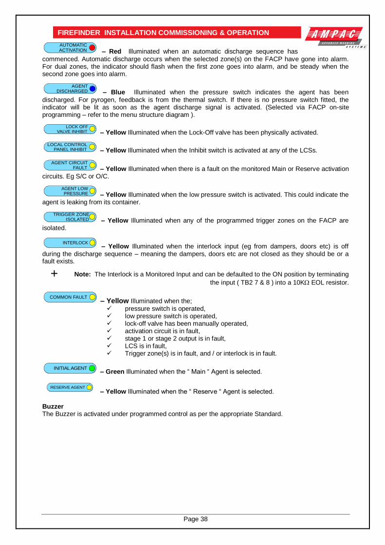
Page 38
FIREFINDER INSTALLATION COMMISSIONING & OPERATION
AUTOMATICACTIVATION – Red Illuminated when an automatic discharge sequence has
commenced. Automatic discharge occurs when the selected zone(s) on the FACP have gone into alarm. For dual zones, the indicator should flash when the first zone goes into alarm, and be steady when the second zone goes into alarm.
AGENTDISCHARGED – Blue Illuminated when the pressure switch indicates the agent has been
discharged. For pyrogen, feedback is from the thermal switch. If there is no pressure switch fitted, the indicator will be lit as soon as the agent discharge signal is activated. (Selected via FACP on-site programming – refer to the menu structure diagram ).
LOCK OFFVALVE INHIBIT – Yellow Illuminated when the Lock-Off valve has been physically activated.
LOCAL CONTROLPANEL INHIBIT – Yellow Illuminated when the Inhibit switch is activated at any of the LCSs.
AGENT CIRCUITFAULT – Yellow Illuminated when there is a fault on the monitored Main or Reserve activation
circuits. Eg S/C or O/C.
AGENT LOWPRESSURE – Yellow Illuminated when the low pressure switch is activated. This could indicate the
agent is leaking from its container.
TRIGGER ZONEISOLATED – Yellow Illuminated when any of the programmed trigger zones on the FACP are
isolated.
INTERLOCK – Yellow Illuminated when the interlock input (eg from dampers, doors etc) is off
during the discharge sequence – meaning the dampers, doors etc are not closed as they should be or a fault exists.
Note: The Interlock is a Monitored Input and can be defaulted to the ON position by terminating
the input ( TB2 7 & 8 ) into a 10K EOL resistor.
COMMON FAULT – Yellow Illuminated when the; pressure switch is operated, low pressure switch is operated, lock-off valve has been manually operated, activation circuit is in fault, stage 1 or stage 2 output is in fault, LCS is in fault, Trigger zone(s) is in fault, and / or interlock is in fault.
INITIAL AGENT – Green Illuminated when the “ Main “ Agent is selected.
RESERVE AGENT – Yellow Illuminated when the “ Reserve “ Agent is selected.
Buzzer The Buzzer is activated under programmed control as per the appropriate Standard.

Page 39
FIREFINDER INSTALLATION COMMISSIONING & OPERATION
Local Control Station Terminal Blocks TB1 & TB2
TB2 Terminal Assignment TB1 Terminal Assignment 1 RS485 + In 1 +27V In 2 RS485 - In 2 0V In 3 RS485 Common 3 +27V Out 4 RS485 + Out 4 0V Out 5 RS485 - Out 6 RS485 Common 7 Interlock+ 8 Interlock-
Local Control Station Layout The Local Control Station is supplied with its own mounting panel. The Comms line is RS485 between the Local Control Station and the Main Control Board.
The Interlock is a monitored input with 10K EOL used to determine if air conditioning dampers and doors are closed. Typically the agent is not discharged until all dampers / doors are closed.
RS 485 OUT
TB2
TB1
SW2
K1
BUZZER BZ1
INTERLOCK
COM
Termination Link
Address Switch
EC3AW3V3 POWER SUPPLY
+
COM
+27V Out 0V
+27V In 0V
+_
+_
RS 485 IN
+_
+
+
1 2
3 4
ON
CN8CN2
Key SwitchManual Release
Inhibit
ManualActivation
Lock OffValve Inhibit
Agent LowPressure
Interlock
AutomaticActivation
Local ControlPanel Inhibit
Trigger ZoneIsolated
Initial Agent
AgentDischarged
AgentCircuit Fault
CommonFault
ReserveAgent
Figure 54: Top PCB Layout Figure 55: Bottom PCB Layout
7.5 Agent Termination Board BRD25ATB
Figure 56: Agent Termination Board PCB Layout
LK1
Q2
SW1
U5
U9 U7
U1
X1
RL6
RL4RL1 RL2 RL5 RL3
CN5
U3U4 U2
U10
RL7
+ LOCK-
+ L.PSW-
RELEASE
C
NC NO///
+L
COMM
NC
NO
-L
C
NC NO///
-+
SIG+
SIG-
LCS CABLE
+ PSW -
Monitored INPUTS
N/0
STAGE2 GASFIRED
+ - N/0 COMN/0 COM +
SYST.INOP.
SCRN+24VDC + -
C
NC NO///
C
NC NO///
-L
NO
NC
COMM
+L-L
NO
NC
COMM
+L
03
/09
/02
0VDC+ -
STAGE1
-COM
30
2-7
87
0
TB7TB6TB5TB4TB3TB2TB1
CN2
CN1
Address SettingCN3 CN427V In
27V to Next Board
RS485 Control In From CN2 of Previous Boardor CN21 of theMain ControlBoard
RS485 Control Out to Next Board or Link 1EOL is Applied
MAIN RESV
+ - Outputs are Monitored
Contact Rating1A & 24V
Contact Rating1A & 24V
Contact Rating1A & 24V
Contact Rating1A & 24V
1 2 3 4
O N
EOLTermination

Page 40
FIREFINDER INSTALLATION COMMISSIONING & OPERATION The Agent Termination Board interfaces to;
1. The FACP via CN1, CN2 continuing the RS485 communications bus if required. LK1 is inserted if this is the last backpan board on the bus.
2. LCS’s ( up to 4 ) via TB1. LK1 is inserted in the last board in the RS485 Bus
3. Monitored Inputs: via TB2. ( EOL Resistance 22K, Series Resistance 4K7 ) (a) Pressure Switch ( PSW ) agent released (b) Low Pressure Switch ( LPSW ) agent storage cylinder pressure has dropped to a pre-
determined level; and (c) Interlock, the manual lock-off valve has been operated.
4. Gas Fired: Output via RL2 N/O contacts rated at 1A @ 24VDC wired to TB3. Used to indicate to other monitoring devices the agent has been released.
5. System Inoperative: via RL1 N/O contacts rated at 1A @ 24VDC wired to TB4. Used to warn by way of signage / audible alarm and/or monitoring that the system is inoperative.
6. Stage 1: Output; initiates the visual and audible Fire Alarm and Evacuate warnings.
(a) Monitored; via RL4 C/O contacts wired to TB5 1 & 2 ( EOL required 10K ) and (b) un-monitored; via RL5 N/O contacts wired to TB5 3 & 4.
7. Stage 2: output; initiates the visual and audible Fire Alarm and Do No Enter warnings
(a) Monitored; via RL6 C/O contacts wired to TB6 1 &2; ( EOL required is 10K ) and (b) Un-monitored; via RL3 N/O contacts wired to TB6 3 & 4
8. Release: Main actuating circuit, monitored (10KΩ EOL required) via TB7 1 & 2 ( 2A current limited ), Release: Reserve actuating circuit, monitored (10KΩ EOL required) via TB7 3 & 4 ( 2A current limited ) (a) To Pyrogen Igniter ( max of 10 )
(b) Metron Igniters ( max of 10 – a series 2watt 18 resister must be added to the circuit ) (c) Solenoid valve ( max current of 2 amps & 27VDC )
7.6 Interface Wiring
Monitored Inputs TB2 1 & 2 Pyrogen,
This input relies on a thermal fuse used in conjunction with 22K EOL and 4K7 series resistors. The type of agent release mechanism has to be set in the Programming Menu for the input to function as per the manufacturers specifications and be in accordance with the relevant Standard.
1 2
PSW
TB2Termination Board
4K7 22KEOL
PyrogenCanister
+ -
PyrogenReleasePoint
FUSE
Pyrogen ReleaseBrd. 302-740
To TB7MAIN or
RESERVERelease
MAIN / RESERVERELEASE
TB1
-VE
+V
E
17/10/00
D1
R1
C1
C2
R2
TB2
302-7400
MAIN RESV
+ -
10K EOL
Solenoid
+ -
TB7
Figure 57: Pyrogen Wiring

Page 41
FIREFINDER INSTALLATION COMMISSIONING & OPERATION Solenoid & Metron
This input relies on N/O or N/C relay contacts used in conjunction with 22K EOL and 4K7 series resistors. The type of agent release mechanism and contacts used has to be set in the Programming Menu for the input to function as per the manufacturers specifications and be in accordance with the relevant Standard.
Note: The PSW, LPSW & the Interlock Mechanisms are allmounted onto the top of the cylinder containing the Agent
TerminationBoard
+ -
4K722KEOL
AgentDistribution
4K7
22K EOL
LPSW LOCK
4K7
22K EOL
PSW
+ - + -
MAIN / RESERVERELEASE
To TB7MAIN or
RESERVERelease
Agent
MAIN RESV
+ -
10K EOL
Solenoid
+ -
TB7
Figure 58: Solenoid, Metron PSW, LPSW and “LOCK” Wiring
LPSW & Lock These inputs are also monitored and should be wired as shown above
1
2
To MonitoringInterface / Device
0V
RL2ATB3
= MOV 35V
*
* *
To SysInop Mon
+
-System Inoperative
1
20V
RL1ATB4
+27V CurrentLimited to1A
Figure 59: Gas Fired Wiring Figure 60: System Inoperative Wiring
As can be seen from above the; Gas Fired Output can be wired to any interfacing or 1A monitoring circuit that requires a closed relay contact to indicate a change of state. This could be a relay or a solid state device. System Inoperative Outputs 27V @ 1A to supply interfacing, signage and aural alarms to indicate the system has been taken out of service or has developed a fault. Stage 1, Stage 2
- ( + )
+ ( - )
*
0V TB5 = Stage 1TB6 = Stage 2
= MOV 35V
*
*
+ve
-ve 10KEOL
1 or 2 Way Signage
To audible / visualdevice or interface
*
Stage 1 or Stage 2
RL3ARL5A
RL4B
RL4A RL6A
Termination Board Relays
RL6B
1
2
3
4
The above circuitry applies to bothTB5 ( Stage 1 ) and TB6 ( Stage 2 )
TB5 / 6
MAIN RESV
+ -
10K EOL
Solenoid
+ -
TB7
Figure 61: Stage 1 and 2 Wiring & Main / Reserve Release Wiring

Page 42
FIREFINDER INSTALLATION COMMISSIONING & OPERATION
7.7 Warning Signs
Description The warning signs are driven by a 2 wire system and may be configured for single or dual stage operation.
An on-board buzzer provides an audible warning which may be disabled by removing JP3.
External evacuation devices, eg sounders may be connected to TB3 of the input termination board. An external mute push-button (N/O contacts) may also be connected to Term 3 on the warning sign PCB to enable the user to silence the internal buzzer and evacuation device. Inserting JP4 disables this function.
Enclosures The IP50 is a metal enclosure. The facia surround is fitted by removing the screw on the left hand side of the enclosure and pulling it away to the left. The facia sign is fitted in place and the tabs bent over to hold it in place. Two holes in the backpan of the chassis allow for mounting.
The IP65 ABS enclosure has 10 screws, tightened evenly but not over tightened, hold the facia in place. Do not over tighten. 4 holes in the backpan allow for mounting.
Specifications:
Operational Voltage 28VDC
Power Consumption Continuous At 24VDC 55mA Stage 1 At 24VDC 140mA Stage 2 (100mA Muted)
IP Ratings IP50 ( Dim: 190H x 315W x 73D mm ) IP65 ( Dim: 200H x 295W x 65D mm )
Environmental -10˚C to +55˚C Dry heat +40˚C @ 0 to 93% Relative Humidity
Installation 1. Remove the backpan from the enclosure to ensure it is not damaged while mounting the
enclosure. 2. Bring the cabling into the enclosure by removing the knockouts most appropriate for the
installation. 3. Mount the enclosure, remount thebackpan, set the configuration and then cable as per the
following diagram. 4. ENSURE THE AGENT IS ISOLATED and test from the Agent Release Module.
Cabling Term 3 (Buzzer Mute) BUZZER MUTE Normally Open [ N/O ] Push Button Switch (Optional) INPUT
Term 4 ( Single pair polarity reversing / 2 Stage Input ) Stage 1 0V – 24VDC
Stage 2 24VDC – 0V
Configuration – Jumper Settings
JP 1 (Continuous / Flashing) JP 2 (Single / Dual Stage) 1-2 Continuous LED's Permanently ON 1-2 Single Stage Full sign on for Stage 1&2
2-3 Flashing (DEFAULT) LED's flashing at 1.5Hz 2-3 Dual Stage (DEFAULT) Half sign on for Stage 1
Full sign on for Stage 2
JP 3 (Enable Buzzer) JP 4 (Disable External Mute) 1-2 ENABLE BUZZER (DEFAULT)
Buzzer activates for both Stage 1 & 2
1-2 EXTERNAL MUTE (DEFAULT)
Disable external mute for internal Buzzer
JP 5 ( Enable External Evacuation Device ) [ not used ] 1-2 ENABLE EXTERNAL EVACUATION External evacuation device will activate on Stage 1 & 2 DEVICE (DEFAULT) with the tone dependent on the input polarity

Page 43
FIREFINDER INSTALLATION COMMISSIONING & OPERATION
INPUT INPUT
LE
VE
L 2
LE
VE
L 1
CO
M +
- + TONE 1+ - TONE 2
TERM 5TERM4
TERM6
TERM3
TERM1
OUTPUT
LE
VE
L 2
LE
VE
L 1
CO
M +
OUTPUT
- + TONE 1+ - TONE 2
BU
ZZ
ER
MU
TE
OUTPUT
EX
TE
RN
AL
SO
UN
DE
R
SIN
GL
E L
EV
EL
DU
AL
LE
VE
L
EN
AB
LE
SO
UN
DE
R(N
OT
US
ED
)
EN
AB
LE
BU
ZZ
ER
DIS
AB
LE
EX
T-M
UT
E
TP14
GND
TP9
TP8
TP7
TP13
TP12
TP11
TP10
TP1
GND
+
FL
AS
HIN
G
CO
NT
INU
OU
S
ROW NOT USED
JP2 JP1 JP3JP5JP4
WARNING SIGN PCB
JP"X"
1 2 3
JUMPERNUMBERING
BUZZER
TERM2
ROW NOT USED
ROW NOT USED TO N/O MUTE SWITCH
WARNING SIGN TERMINATION BRD
2 WIRE INPUT FROM AGENT TERMINATION BOARD
BUZZER MUTETO NEXT WARNING SIGN IF USEDFIT 10K EOL TO LAST SIGN (MAX 6)
10K
VANTAGESOUNDER(MAX 1)
UNSCREW THE 4 SLOTTEDSCREWS TO REMOVE PCB
IN
-
OU
T
+
+
-
COM+
STG1
STG2
TB1
TB3
TB2BRD 42WTB2- A CN1/2
NO
TU
SE
D
BACKPAN RETAININGSCREWS IN EACH CORNER
Figure 62: Warning Sign PCB Layout and Cabling
TERM 4
- +TONE 1
INPUTWARNINGSIGN
( MAXIMUMOF 6 INTOTAL )
10K1. (-) EVAC
2. (-) EVAC
3. (-) ALERT
4. (-) ALERT
5. (+) POS
6. (+) POS
VANTAGE SOUNDER( ORDER CODE 205-0062 )
10
K
FIT 10K EOL TO LAST SIGN ON CHAIN
AGENT TERMINATION BOARD
RELEASE
-+
STAGE2
+ - N/0 COMN/0 COM +
SYST.
+ - + -
STAGE1
-
TB7TB6TB5TB4
MAIN RESV
+ - Outputs are MonitoredINOP
+ -TONE 2
TO NEXT WARNING SIGN IFMULTIPLE SIGNS ARE USED
BRD 42WTB1-A
IN
-
OU
T
+
+
-
COM+
STG1
STG2
TB1
TB3
TB2
NOTE: THE WARNING SIGNTERMINATION BRD IS MOUNTED
ON THE INSIDE BACK PLATEOF THE WARNING SIGN
BRD 42WTB2-A
CN1 CN2
Figure 63: 2 Wire Cabling from the Agent Termination Board to the Warning Sign/s & Evacuation Device/s

Page 44
FIREFINDER INSTALLATION COMMISSIONING & OPERATION
8 Expanding the System & Networking Expanding the system can be achieved in various ways and requires the use of boards specifically designed for communications purposes and boards that actually expand the system.
8.1 Expansion Controller An Expansion Controller ( Fast Fit Kit Number 159-0077 ) can be described as a Main Controller without a Front Panel. A maximum of 3 can be introduced into any one Node, that is into any one FACP and require Controller Interface Cards ( CIC ) and Network Interface Cards in order to communicate with the Main Board / Controller. Connecting Controllers together ( Networking within the same cabinet ) expands the system beyond 8 Slave CPU’s, that is the Main Board plus an Expansion Board. Networking in this way offers the added advantage that the RS422 communication bus is internal and all Controllers are physically and logically located at the same Node. It is now possible to Network up to 32 Slave CPU’s in one cabinet with each Slave CPU connected to an Addressable Loop, 16 Conventional Zone Board or Digital I/O Board. With this configuration only one Controller has a Front Panel Board.
8.2 Networking When FACP’s are connected to each other they form a “ NETWORK “. Individual FACP’s in the Network are referred to as NODES. The Network as defined by the limitations of the installation can consist of a number of Nodes, the number of Nodes being dependant on the configuration of each Node. The Network is Peer to Peer with the entire system configuration being stored at each Node. The system is then programmed so that information can be made invisible to particular Nodes or visible to all Nodes. Likewise system commands can be global or restricted to specific parts of the network. The entire system can be programmed via a data loop from Node 1 in the Network.
IMPORTANT While it is important that proper documentation is kept and maintained for any installation it becomes even more important as a system develops into the larger types described above.

Page 45
FIREFINDER INSTALLATION COMMISSIONING & OPERATION
Figure 64: Example of 3 Expansion Controllers within an FACP
NETWORK INTERFACE CARD(NIC) 302-7240
27VDC POWER
CIC 27V OUTPUT OR EXTERNAL POWER SUPPLY
CN
1
CN2
1
CN
1
CN2
1
CN
1
CN2
1
CN8
CN1
CN6
CN3
CN15
CN4
SW1
BZ1 CN5
CN2CN7
CN11
CN16
CN9
CN17
CN13
CN10
CN
18
SW3
LK2
+
cba
4 3 2
BRIGADE I/F
FRONT PANELEXPANSION LEDSEXPANSI ON PANEL
MODEM
BACKLIGHT
27
V I
N
RESET
PRI NTER
PSU MONI TOR
LOOP COMMS
NODE ADDRESS
1
cba
RS485 MULTIDROP (SINGLE PAIR SHIELDED)CABLE TYPE BELDEN 9841
REMOTE LEDREPEATER302 - 71516 WAY
RIBBON
CONTROLLER INTERFACE CARD (CIC) 302-7250
10 WAY RIBBON
COMMS IN
COMMS OUT
RS232 NOT AVAILABLE
MUTE
TEST
N/F
SC
RT
X-
TX
++
27
OV
+27
K2
CN5
CN
1
CN
2
CN6
CN
4
TB3
TB1
TB5
TB4
BZ
1
SW6
SW4
SW5
SW2
SW7
CN7 SW3
D2 D3
D4
+
POW ER OUT
BUZZER
RESET
LAMP
FAULTNORMALPOWER ONLED DISPLAY
N/O
N/C
C0
VG
PI
OU
T
OV
GN
D
IN
CPU RESET
OFF ON
ADDRESS
SYSTEM
LEDS FLASH
FA
CT
OR
YU
SE
ON
LY
SC
RT
X-
TX
+
FIT K1 ONLAST MIMICONLY
FIT K2
FOR BUZZER
A LM
PRE
DBA
FLT
N O M
RST
LT
B M
BI
EVC
BZ
1
2
3
4
5
LED
6
7
8
9
10
11
12
13
14
15
16
17
18
19
20
21
22
23
24
25
26
27
28
29
30
31
32
LAMP
LED AUX 5V
CN
3
SW
3
SW
1
TB
1
TB
2
SW
2
CN
2
CN
5
CN
1
CN
4
TB
3
2A
F1
ISOLATE
CTS
RTS
RXD
TXD
COM
OF
F
ON
RE
SE
T
DA
BC
S-
+D
AB
CS
-+
CO
MM
S O
UT
CO
MM
S IN
abc
1
321
OUT
CTS
RTS
RXD
TXD
COM
SCRN
TRX-
TRX+
2A
0V
+27V
TB3
K2
K1
F1
CN1
TB2
TB1
CN
5C
N6
CN3
NOTE:ONLY RS485 OR RS422NOT BOTH
FIREFINDER FACPNODE 1 CONTROLLER 1
CONTROLLER302-669302-674302-675
CIC 27V OUTPUT OR EXTERNAL POWER SUPPLY
CN
1
CN2
1
CN
1
CN2
1
CN
1
CN2
1
CN8
CN1
CN6
CN3
CN15
CN4
SW1
BZ1CN5
CN2CN7
CN11
CN16
CN9
CN17
CN13
CN10
CN
18
SW3
LK2
+
cba
4 3 2
BRIGADE I/F
FRONT PANELEXPANSION LEDSEXPANSION PANEL
MODEM
BACKLIGHT
27
V I
N
RESET
PRI NTER
PSU MONI TOR
LOOP COMMS
NODE ADDRESS
1
cba
RS485 MULTIDROP (SINGLE PAIR SHIELDED)CABLE TYPE BELDEN 9841
REMOTE LEDREPEATER 302 - 715
16 WAY RIBBON
CONTROLLER INTERFACE CARD (CIC) 302-7250
MUTE
TEST
N/F
SC
RT
X-
TX
++
27
OV
+2
7
K2
CN5
CN
1
CN
2
CN6
CN
4
TB3
TB1
TB5
TB4
BZ
1
SW6
SW4
SW5
SW2
SW7
CN7 SW3
D2 D3
D4
+
POW ER OUT
BUZZER
RESET
LAMP
FAULTNORMALPOW ER ONLED DISPLAY
N/O
N/C
C0
VG
PI
OU
T
OV
GN
D
IN
CPU RESET
OFF ON
ADDRESS
SYSTEM
LEDS FLASH
FA
CT
OR
YU
SE
ON
LY
SC
RT
X-
TX
+
FIT K1 ON
LAST MIMICONLY
FIT K2
FOR BUZZER
A LM
PRE
DBA
FLT
N O M
RST
LT
B M
BI
EVC
BZ
1
2
3
4
5
LED
6
7
8
9
10
11
12
13
14
15
16
17
18
19
20
21
22
23
24
25
26
27
28
29
30
31
32
LAMP
LED AUX 5V
321
OUT
CTS
RTS
RXD
TXD
COM
SCRN
TRX-
TRX+
2A
0V
+27V
TB3
K2
K1
F1
CN1
TB2
TB1
CN
5C
N6
CN3
NOTE:ONLY RS485 OR RS422NOT BOTH
302-669302-674302-675
10 WAY RIBBON
INCN2
REMOTE LCD REPEATER302 - 720
RS422 COMMS LOOP
COMMS OUT
COMMS IN
TWO PAIR SHIELDEDBELDEN 8132 OR 9842
OPTIONAL RS232 (AVAILABLE FORHIGH LEVEL INTERFACE ORGRAPHICS OR REMOTE SERIAL PRINTER)
BZ
1
RV
1
SW
2
CN
1
SW
3
TB
1T
B2
CN
7
CN
2
SW
1
CN
5
Ja
n 1
99
9
AP
I 7
20
+
LC
DO
FF
ON
PO
WE
RB
AC
KL
IGH
T-
AB
CD
S-
+A
BC
DS
-+
BA
CK
LIG
HT
+
RE
SE
T
CO
NT
RA
ST
PR
INT
ER
DE
BU
G
CO
MM
S O
UT
CO
MM
S I
N
COM
TXD
RXD
RTS
CTS
TO
P L
AY
ER
302-669302-674302-675
CIC 27V OUTPUT OR EXTERNAL POWER SUPPLY
CN
1
CN2
1
CN
1
CN2
1
CN
1
CN2
1
CN8
CN1
CN6
CN3
CN15
CN4
SW1
BZ1 CN5
CN2 CN7
CN11
CN16
CN9
CN17
CN13
CN10
CN
18
SW3
LK2
+
cba
4 3 2
BRIGADE I/F
FRONT PANELEXPANSION LEDSEXPANSION PANEL
MODEM
BACKLIGHT
27
V I
N
RESET
PRI NTER
PSU MONI TOR
LOOP COMMS
NODE ADDRESS
1
cba
RS485 MULTIDROP (SINGLE PAIR SHIELDED)CABLE TYPE BELDEN 9841
REMOTE LEDREPEATER 302 - 715
16 WAYRIBBON
CONTROLLER INTERFACE CARD (CIC) 302-7250
MUTE
TEST
N/F
SC
RT
X-
TX
++
27
OV
+2
7
K2
CN5
CN
1
CN
2
CN6
CN
4
TB3
TB1
TB5
TB4
BZ
1
SW6
SW4
SW5
SW2
SW7
CN7 SW3
D2 D3
D4
+
POW ER OUT
BUZZER
RESET
LAMP
FAULTNORMALPOW ER ONLED DISPLAY
N/O
N/C
C0
VG
PI
OU
T
OV
GN
D
IN
CPU RESET
OFF ON
ADDRESS
SYSTEM
LEDS FLASH
FA
CT
OR
YU
SE
ON
LY
SC
RT
X-
TX
+
FIT K1 ON
LAST MIMICONLY
FIT K2
FOR BUZZER
A LM
PRE
DBA
FLT
N O M
RST
LT
B M
BI
EVC
BZ
1
2
3
4
5
LED
6
7
8
9
10
11
12
13
14
15
16
17
18
19
20
21
22
23
24
25
26
27
28
29
30
31
32
LAMP
LED AUX 5V
321
OUT
CTS
RTS
RXD
TXD
COM
SCRN
TRX-
TRX+
2A
0V
+27V
TB3
K2
K1
F1
CN1
TB2
TB1
CN
5C
N6
CN3
NOTE:ONLY RS485 OR RS422NOT BOTH
302-669302-674302-675
CIC 27V OUTPUT OR EXTERNAL POWER SUPPLY
CN
1
CN2
1
CN
1
CN2
1
CN
1
CN2
1
CN8
CN1
CN6
CN3
CN15
CN4
SW1
BZ1 CN5
CN2CN7
CN11
CN16
CN9
CN17
CN13
CN10
CN
18
SW3
LK2
+
cba
4 3 2
BRIGADE I/F
FRONT PANELEXPANSION LEDSEXPANSION PANEL
MODEM
BACKLIGHT
27
V I
N
RESET
PRI NTER
PSU MONI TOR
LOOP COMMS
NODE ADDRESS
1
cba
RS485 MULTIDROP (SINGLE PAIR SHIELDED)CABLE TYPE BELDEN 9841
REMOTE LEDREPEATER 302 - 715
16 WAYRIBBON
CONTROLLER INTERFACE CARD (CIC) 302-7250
MUTE
TEST
N/F
SC
RT
X-
TX
++
27
OV
+2
7
K2
CN5
CN
1
CN
2
CN6
CN
4
TB3
TB1
TB5
TB4
BZ
1
SW6
SW4
SW5
SW2
SW7
CN7 SW3
D2 D3
D4
+
POW ER OUT
BUZZER
RESET
LAMP
FAULTNORMALPOW ER ONLED DISPLAY
N/O
N/C
C0
VG
PI
OU
T
OV
GN
D
IN
CPU RESET
OFF ON
ADDRESS
SYSTEM
LEDS FLASH
FA
CT
OR
YU
SE
ON
LY
SC
RT
X-
TX
+
FIT K1 ONLAST MIMICONLY
FIT K2
FOR BUZZER
A LM
PRE
DBA
FLT
N O M
RST
LT
B M
BI
EVC
BZ
1
2
3
4
5
LED
6
7
8
9
10
11
12
13
14
15
16
17
18
19
20
21
22
23
24
25
26
27
28
29
30
31
32
LAMP
LED AUX 5V
321
OUT
CTS
RTS
RXD
TXD
COM
SCRN
TRX-
TRX+
2A
0V
+27V
TB3
K2
K1
F1
CN1
TB2
TB1
CN
5C
N6
CN3
NOTE:ONLY RS485 OR RS422NOT BOTH
INCN2
INCN2
INCN2
EXPANSION CONTROLLERNODE 1 C2
10 WAY RIBBON
10 WAY RIBBON
EXPANSION CONTROLLERNODE 1 C3
EXPANSION CONTROLLERNODE 1 C4

Page 46
FIREFINDER INSTALLATION COMMISSIONING & OPERATION
Figure 65: Example of Networking 2 Panels with LCD Repeaters
Figure 66: Example of Networking 2 Panels and LED Mimic
REMOTE LCD REPEATER 302 - 720
FIREFINDER PANEL No1
CONTROLLER302-669302-674302-675
NETWORK INTERFACE CARD (NIC) 302 - 724
FIREFINDER PANEL No2
27VDC POWER
27VDC POWER
CONTROLLER302-669302-674302-675
RS422 COMMS LOOP
NETWORK INTERFACE CARD (NIC) 302 - 724
TO OTHER LCD REPEATER PANELSIF INSTALLED
IN
OUT
CN
1
CN2 1
CN
1
CN2
1
CN
1
CN2
1
CN
1
CN2
1
CN
1
CN2
1
CN
1
CN2
1
RV1
CN8
CN1
CN6
CN3
CN15
CN4
SW1
BZ1CN5
CN2CN7
CN11
CN16
CN9
CN17
CN13
CN10
SW3
LK2
RN17
+
cba
4 3 2
BRIGADE I/F
FRONT PANELEXPANSION LEDSEXPANSION PANEL
MODEM
BACKLIGHT
27
V IN
RESET
PRINTER
PSU MONITOR
LOOP COMMS
NODE ADDRESS
1
RV1
CN8
CN1
CN6
CN3
CN4
SW1
BZ1CN5
CN7
CN11
CN16
CN17
CN13
CN10
CN
18
SW3
RN17
+
cba
4 3 2
BRIGADE I/F
FRONT PANELEXPANSION LEDSEXPANSION PANEL
BACKLIGHT
27
V IN
RESET
PRINTER
PSU MONITOR
LOOP COMMS
NODE ADDRESS
1
C1
8
cba
cba
COMMS IN
COMMS OUT
COMMS OUT
COMMS IN
COMMS IN
COMMS OUT
16 WAY RIBBON
TWO PAIR SHIELDEDBELDEN 8132 OR 9842
OPTIONAL RS232 (AVAILABLE FORHIGH LEVEL INTERFACE ORGRAPHICS OR REMOTE SERIAL PRINTER)
OPTIONAL RS232 (AVAILABLE FOR HIGH LEVEL INTERFACE ORGRAPHICS OR REMOTE SERIAL PRINTER)
OPTIONAL RS232 (AVAILABLE FORHIGH LEVEL INTERFACE ORGRAPHICS OR REMOTE SERIAL PRINTER)
16 WAY RIBBON
BZ
1
RV
1
SW
2
CN
1
SW
3
TB
1T
B2
CN
7
CN
2
SW
1
CN
5
Ja
n 1
999
AP
I 7
20
+
LC
DO
FF
ON
PO
WE
RB
AC
KL
IGH
T-
AB
CD
S-
+A
BC
DS
-+
BA
CK
LIG
HT
+
RE
SE
T
CO
NT
RA
ST
PR
INT
ER
DE
BU
G
CO
MM
S O
UT
CO
MM
S I
N
COM
TXD
RXD
RTS
CTS
TO
P L
AY
ER
CN
3
SW
3
TB
1
TB
2
CN
2
CN
5
CN
1
CN
4
TB
3
2A
F1
CTS
RTS
RXD
TXD
COM
RE
SE
T
DA
BC
S-
+D
AB
CS
-+
CO
MM
S O
UT
CO
MM
S IN
abc
1
CN
3
SW
3
TB
1
TB
2
CN
2
CN
5
CN
1
CN
4
TB
3
2A
F1
CTS
RTS
RXD
TXD
COM
RE
SE
T
DA
BC
S-
+D
AB
CS
-+
CO
MM
S O
UT
CO
MM
S IN
abc
1
NOTES:MAXIMUM DISTANCES BETWEEN PANELS = 1.2KMIF GREATER DISTANCE ARE REQUIRED A RS422 REPEATER(BLACK BOX 352A or 352A-F) TO BE FITTED EVERY 1.2KMAFTER THE FIRST 1.2KMCABLE TO BE USED = BELDEN 8132 OR 9842 TWO PAIR SHIELDED.
FIREFINDERPANEL No1
CONTROLLER302-669302-674302-675
NETWORK INTERFACE CARD(NIC) 302-7240
2 PAIR SHIELDED CABLE TYPE BELDEN 8132 OR 9842
FIREFINDERPANEL No2
NETWORK INTERFACECARD (NIC) 302-7240
27VDC POWER
27VDC POWER
CONTROLLER302-669302-674302-675
CIC 27V OUTPUT OR EXTERNAL POWER SUPPLY
OPTIONAL RS232(AVAILABLE FOR HIGH LEVEL INTERFACE OR GRAPHICS OR REMOTE SERIAL PRINTER)
CN
1
CN2
1
CN
1
CN2
1
CN
1
CN2
1
CN
1
CN2
1
CN
1
CN2
1
CN
1
CN2
1
CN8
CN1
CN6
CN3
CN15
CN4
SW1
BZ1 CN5
CN2 CN7
CN11
CN16
CN9
CN17
CN13
CN10
CN
18
SW3
LK2
+
cba
4 3 2
BRIGADE I/F
FRONT PANELEXPANSION LEDSEXPANSION PANEL
MODEM
BACKLIGHT
27
V IN
RESET
PRINTER
PSU MONITOR
LOOP COMMS
NODE ADDRESS
1
RV1
TH
1
CN8
CN1
CN6
CN3
CN4
SW1
BZ1 CN5
CN2CN7
CN11
CN16
CN9
CN17
CN10
CN
18
SW3
LK2
+
cba
4 3 2
BRIGADE I/F
FRONT PANELEXPANSION LEDSEXPANSION PANEL
MODEM
BACKLIGHT
27
V IN
RESET
PRINTER
PSU MONITOR
LOOP COMMS
NODE ADDRESS
1
cba
cba
CN2
RS485 MULTIDROP (SINGLE PAIR SHIELDED)CABLE TYPE BELDEN 9841
REMOTE LED REPEATER 302-715
16 WAY RIBBON
CONTROLLER INTERFACE CARD (CIC) 302-7250
10 WAY RIBBON
COMMS IN
COMMS OUT
RS232 NOT AVAILABLE
RS422 COMMS LOOP
16 WAY RIBBON
COMMS IN
COMMS OUT
MUTE
TEST
N/F
SC
RT
X-
TX
++
27
OV
+2
7
K2
CN5
CN
1
CN
2
CN6
CN
4
TB3
TB1
TB5
TB4
BZ
1
SW6
SW4
SW5
SW2
SW7
CN7 SW3
D2 D3
D4
+
POWER OUT
BUZZER
RESET
LAMP
FAULTNORMALPOWER ONLED DISPLAY
N/O
N/C
C0
VG
PI
OU
T
OV
GN
D
IN
CPU RESET
OFF ON
ADDRESS
SYSTEM
LEDS FLASH
FA
CT
OR
YU
SE
ON
LY
SC
RT
X-
TX
+
FIT K1 ONLAST MIMICONLY
FIT K2
FOR BUZZER
ALM
PRE
DBA
FLT
NOM
RST
LT
BM
BI
EVC
BZ
1
2
3
4
5
LED
6
7
8
9
10
11
12
13
14
15
16
17
18
19
20
21
22
23
24
25
26
27
28
29
30
31
32
LAMP
LED AUX 5V
CN
3
SW
3
C3
4C3
3
EC
3A
21
H
HY
1
SW
1
TB
1
TB
2
SW
2
CN
2
CN
5
CN
1
CN
4
TB
3
2A
F1
ISOLATE
CTS
RTS
RXD
TXD
COM
+
OF
F
ON
RE
SE
T
DA
BC
S-
+D
AB
CS
-+
CO
MM
S O
UT
CO
MM
S IN
abc
1
CN
3
SW
3
SW
1
TB
1
TB
2
SW
2
CN
2
CN
5
CN
1
CN
4
TB
3
2A
F1
ISOLATE
CTS
RTS
RXD
TXD
COM
OF
F
ON
RE
SE
T
DA
BC
S-
+D
AB
CS
-+
CO
MM
S O
UT
CO
MM
S IN
abc
1
NOTES:MAXIMUM DISTANCE BETWEEN PANELS = 1.2KMIF GREATER DISTANCE ARE REQUIRED A RS485 REPEATER (BLACK BOX IC155A) TO BE FITTED EVERY 1.2KM AFTER THE FIRST 1.2KM. CABLE TO BE USED = BELDEN 9841 SINGLE PAIR SHIELDED.CABLE TO BE USED = BELDEN 8132 OR 9842 TWO PAIR SHIELDED.
POWER REQUIREMENTS27VDC CAN BE DERIVED FROM THE FIREFINDER ORAN EXTERNAL APPROVED 27VDC SUPPLY CAN BE USED.AND WIRED INTO TB1 + AND - TERMINALS
DEPENDING ON CONFIGURATION OF PANEL SOME COMMUNICATIONS CHANNELS MAY NOT BE AVAILABLE
321
OUT
CTS
RTS
RXD
TXD
COM
SCRN
TRX-
TRX+
2A
0V
+27V
TB3
K2
K1
F1
CN1
TB2
TB1
CN
5C
N6
CN3
NOTE:ONLY RS485 OR RS422NOT BOTH

Page 47
FIREFINDER INSTALLATION COMMISSIONING & OPERATION
8.3 Expansion Board The Expansion Connection Board is used to increase the capacity of the controller from 4 Slave CPU’s to 8. The Expansion Board must be mounted within 200mm of the Controller. Connection from the Controller to the Expansion Board is made via a 20 way flat cable Connections
Connector Connects to CN1 To Main Controller CN2 CN2 Slave CPU 2 CN3 Slave CPU 3 CN4 Slave CPU 4 CN5 On board Slave CPU to 302-670. 302-671 and 302-672
Board Overlay
It should be noted that Slave CPU number 5 is an integral part of the Expansion Board, only Slave CPU’s 6, 7 and 8 are plug ins.
Figure 67: Expansion Board
30
2 -
68
80
J
UN
98
76
8
RN
5
RN
4
C15
U1
0C
16
C1
8
C2
0
C2
2
C2
4
C2
6
C2
7
C2
8
U11
U5
RN
3
U6
U4
C7X1
CN
5
C5
C6
TP
1
R1
RN
2
U2
U1
C2
+
C1
CN
1
C2
3
R3
R2
U1
2
C11
C1
2
C1
3
C1
4
C1
7
C1
9
C2
1
C2
5
D3
L1
C2
9
TP
2
C1
0C8
U8
U7
U9
C9
D1
D2
C3
U3
RN
1
C4
CN
2C
N3
CN
4
Sla
ve
CP
US
lav
e C
PU
Sla
ve
CP
U
To CN2 of the Main Controller
Slave CPU 5
Note: Slave CPU 5 is incorporated on the Expansion Borad
Slave CPU's 6,7,& 8 all mount ontothe Expansion Board in the same wayas they do to the Main Controller

Page 48
FIREFINDER INSTALLATION COMMISSIONING & OPERATION
8.4 Controller Interface Card The Controller Interface Card (302-725) provides connections to the communication ports on a Controller. The module connects to the Loop Communication connector (CN18) on the 302-674. It may provide two communications ports (RS232 and RS485) dependent upon the mode in which it is used. RS232 is available for communications with graphics and building management systems at terminal block TB2 terminals A to E. RS485 is used to drive Remote LED Mimics and is available at TB1 terminals A to C.
321
OUT
IN
302-725
2A
TB3
K2K1
CN1U8
U7
U9
U10
U13
U11
U6
U4
U5
U1
U12
U2
U3
TB2
TB1
CN5
CN6
CN3
CN2
TO LOOPCOMMS (CN18) OF THE MAIN CONTROLLER
TO PREVIOUS CIC CN3 (OUT)
TO CN2 ( IN ) OF NEXT CIC OR CN1 OF THE NIC
27VDC IN
AUX FUSED ( F1 ) 27VDC OUT
RS232 COMMS OUTPUTHLI / GRAPHICS
RS485 COMMS OUTPUTLED MIMICS
+ -
+ -
- - -- - -
K1, K2:LINK PINS 1 & 2 ON FIRST CIC ONLY
COM
TXD
RXD
RTS
CTS
SCRN
TRX-
TRX+
0V
+27V
F1
Figure 68: Controller Interface Card
8.5 Network Interface Card The Network Interface Card (302-724) allows the networking of multiple panels in different combinations, from Data Gathering panels to Peer to Peer panels. The NIC provides two communication buses RS232 and RS422. The NIC can either connect to the main board via connector CN18 (Loop Comms) or to a Controller Interface Card connector CN3 (Out) The RS422 is used to communicate with any LCD Repeater Panels that may be on the system. This output is available at TB2 terminals 1 to 7. Maximum distances between Panels is 1.2Km. RS232 is also available from TB1 terminals 1 to 5.
CN3
SW3 U15
U1
U6
EC3A21HHY1
RL2
RL1
RL4
RL3
SW1ADDRESSSETTING
TB1
TB2
SW2
CN2
CN5
U3
CN1
U2
U4
U14
U8 U12
U11U9
U10
U13
U5
U7
CN4
TB3ISOLATEO
FF
ON
RESETabc
1
TO CN3 (OUT) OF THE CONTROLLERINTERFACE CARD IF CIC IS INSTALLED
TO CN18 (LOOP COMMS) OF THE MAIN CONTROLLER (STAND ALONE USE)
27VDC (CN4,5) IN / OUT
+-
+-
ON
1 2 3 4 5 6 7 8
2A
COM
TXD
RXD
RTS
CTS
S
D
C
B
A
+27v
0V
S
D
C
B
A
+27v
0V
ON
1 2 3 4 5 6 7 8
RS232 COMMS OUTPUT
RS422 COMMS OUT
RS422COMMS IN
F1 FUSED 27V OUT
To Remote Mimic
LCD RepeaterOther Panels
Graphics or BMS
F1 FUSED 27V OUT To Remote Mimic
Note:The ISOLATE Switchturns OFF the boardand effectivelyS/C's the O/P's
F1
Figure 69: Network Interface Card

Page 49
FIREFINDER INSTALLATION COMMISSIONING & OPERATION
8.6 LED Mimic Board The LED Mimic Board 302-715 remotely mimics the Main Panel’s LED’s and switches. RS485 protocol is used to communicate with the Main Panel. The Mimic can therefore display the status of 32 Zones, 5 specific common outputs ( Alarm, Pre-alarm, DBA, Fault, Normal ) and can be configured to have 5 input switches ( Mimic Reset, Lamp Test, Buzzer Mute, Bell Isolate, Evacuate ), 1 remote Buzzer output as well as 1 software configurable 1A relay output and 1 voltage free driven input. On board switches are,
SW1: turns off the LED’s
SW3: resets the CPU SW4: resets the LED’s SW5: tests the LED’s
SW2 /1-5: sets the board address
SW2 /6: configured OFF for FACP
SW2 /8: sets the LED’s to flash or be steady
SW6: mutes the Buzzer
The Remote LED Mimic board connects to the external RS485 Communication bus via the Controller Interface Card (C.I.C). Up to 31 of these boards may be connected together. The comms is NOT a redundant bus.
+
Aux 5V 500mA O/Pfor LED Expansion
BUZZER MUTE
LAMPRESET
LAMPTEST
FAULTNORMALPOWER ONLED DISPLAY
N/O
N/C
C0V
GP
I
302-715
OUT TB3
-
+-
+
GN
D
CPU RESET
OFF ON
ADDRESS
SYSTEM
LEDS FLASH
FA
CT
OR
YU
SE
ON
LY
SH
BA
SH
BA
K1
K2
ALM
PRE
DBA
DFT
NOM
RST
LT
BM
BI
EVC
BZ
1
2
3
4
5
LED
6
7
8
9
10
11
12
13
14
15
16
17
18
19
20
21
22
23
24
25
26
27
28
29
30
31
32
D4D3D2
SW3
CN7
SW7
SW2
SW5
SW4
SW6
BZ
1
U10
RL1
TB4
TB5
IN TB1
U7
U9
U8
U6
CN4
U4
CN6
U2
U5
Q1
HY1
CN3
CN2
CN1
U3
CN5
Q2
FRONTPANELCOMMON LEDOUTPUTS (CN5)
ZONE LEDS1-8 (CN1)
ZONE LEDS9-16 (CN1)
ZONE LEDS17-24 (CN1)
ZONE LEDS25-32 (CN1)
Relay O/P
Programable I/P
RS485 O/P
RS485 I/PFrom TB1 CIC
27V IN
Fit Link K1 toLast Mimic Only
Voltage Free Changeover Contacts max 1A
Must be Voltage Free Contact
FRONTPANEL SWITCHINPUTS
+ -
To Next LED Mimic if Required
27V O/P
SW2 Settings1-5, Address ( Max 31 )6, Configuration set to OFF for FACP set to ON for EVAC7, Not used8, LED Setting ON = Flash OFF = Steady
Iq = 8mA
Fit Link K2for Buzzerto Sound
ON1 2 3 4 5 6 7 8
ON1 2 3 4
SW1
NOT FITTEDFOR FACP
Figure 70: Remote LED Mimic Board

Page 50
FIREFINDER INSTALLATION COMMISSIONING & OPERATION
Alarm (Red)
Pre-Alarm (Red)
DBA (Yellow)Defect (Yellow)
Normal (Green)
Reset (momentary)Lamp Test (momentary)
Buzzer Mute (momentary)Bell Isolate (keyswitch option available)
Evacuate (keywsitch option available)
32 ZONE MIMIC LEDS ( 8 PER CONNECTOR)
BZ-
BZ+
Buzzer
2526272829303132
CN4
1718192021222324
CN3
910111213141516
CN2
12345678
CN1
CN5
EVC
ALM
PRE
DBA
FLT
RST
LT
BM
BI
NOM
BZ
ZONES 1 - 8
ZONES 9 - 16
ZONES 17 - 24
ZONES 25 - 32
ZONES
Figure 71: Control and LED Indication Internal Connections
If more than one LED is required per Zone, use the AUX 5V Output to supply the extra current.

Page 51
FIREFINDER INSTALLATION COMMISSIONING & OPERATION
8.7 Remote Expansion LED Board There are three options available. Option 1
ON
1
2
3
4
5
6
7
8
302 715 REMOTE LED INDICATOR BOARD
REMOTE BUZZER
EVACUATION SW
BELL ISOLATE SW
BUZZER MUTE SW
LAMP TEST SW
RESET SW
302 733 REMOTE EXPANSION LED BOARD
26 WAY RIBBON
16 WAY RIBBON
16 WAY RIBBON
RS485 IN FROM FIREFINDER CIC
1.2K Max
27VDC-+
MUTE
TEST
N/F
SC
RT
X-
TX
++
27
OV
+27
K1
K2
Q2
CN5
X1
U3
CN1
CN2
CN3
HY1
Q1
U5
CN6
CN4
U8
U9
U7
TB3
TB1
TB5
TB4
RL1
U10
SW6
SW4
SW5
SW2
SW7
CN7 SW3
D2 D3
D4
POWER OUT
BUZZER
RESET
LAMP
FAULTNORMALPOWER ONLED DISPLAY
N/O
N/C
C0
VG
PI
OU
T
OV
GN
D
IN
CPU RESET
OFF O N
ADDRESS
SYSTEM
LEDS FLASH
FA
CT
OR
YU
SE
ON
LYS
CR
TX
-T
X+
FIT K1 ONLAST MIMIC
ONLY
FIT K2
FOR BUZZER
ALM
PRE
DBA
FLT
NOM
RST
LT
BM
BI
EVC
BZ
1
2
3
4
5
LED
6
7
8
9
10
11
12
13
14
15
16
17
18
19
20
21
22
23
24
25
26
27
28
29
30
31
32
LAMP
LED AUX 5V
U2
BZ
1 +
U4
U6
TB2
TB1
D2
CN1
D10
D4
D3
D20
D19
D18
D17
D15
D14
D13
D12
D11
D9
D8
D7
D6
D5
D1
CN3
CN2
D21
RE
SE
TL
AM
P T
ST
BZ
MU
TE
BE
LL IS
OL
EV
AC
BZ
+B
Z-
ALARM
PRE-ALM
DBA
DFCT
NORM
D16
IF APPLICABLE CN3, CN4 CONNECT TO CN2, CN3RESPECTIVELY OF 2nd REMOTE EXPANSION LEDBOARD FOR ZONES 17 - 32
IF APPICABLE ONLYLOWER SECTIONOF BOARD IS USEDFOR ZONES 17 - 32
Figure 72: Remote LED Expansion Board Layout and Wiring to the Remote Indicator Board

Page 52
FIREFINDER INSTALLATION COMMISSIONING & OPERATION Option 2 Option
3
302 701
R1
R2
R3
CN3
R4
R7
R8
R9
R10
R11
R12
R13
R14
R15
R16
R17
R18
R19
R20
R5
R6
CN5
CN4
D18
D5
D6
D7
D8
D9
D10
D11
D12
D13
D14
D16
D15
D17
D19
D20
D4
D3
D2
D1
ALARM
DBA
DEFECT
NORMAL
ZONE 1
ZONE 2
ZONE 3
ZONE 4
ZONE 5
ZONE 6
ZONE 7
ZONE 8
ZONE 9
ZONE 10
ZONE 11
ZONE 12
ZONE 13
ZONE 14
ZONE 15
ZONE 16
CN5
CN4
16 WayI/O
Board 2
16 WayI/O
Board 1
CN5
Slave CPUto 16 Way
I/O Board 1
Slave CPUto 16 Way
I/O Board 2
15-20MMax
15-20MMax
2-3MMax
2-3MMax
ALARM
DBA
DEFECT
NORMAL
-+-
27VDC In
Control InFromSCPUMax 3M
Note:This is the methodused for the displaywithin the FACP
ControlOut
302 706
R1
D1
D2
R2
U7
+
C9
+ C10
C5
U1
R3
R4
D3
D4
D21
R22
D6
D5
R6
R5
CN6
D9
D8
D7
R9
R8
R7
U2
C6
R24
D12
D11
D10
R13
R12
R11
R10
C3
CN1 R21
C1
R23
U3
D15
D14
D13
R16
R15
R14 U5C7
C8
U6
C12
D17
D16
D18
R19
R18
R17C11
R25
U4
D20
D19
R20
CN2
SlaveCPU
16 WayI/O
Board 1/2302 701
2-3M Max15-20 M Max
SlaveCPU 302 706
2-3M Max
Figure 73: 302 701 & 706 Remote ( Note maximum distances) LED Expansion Board Layouts
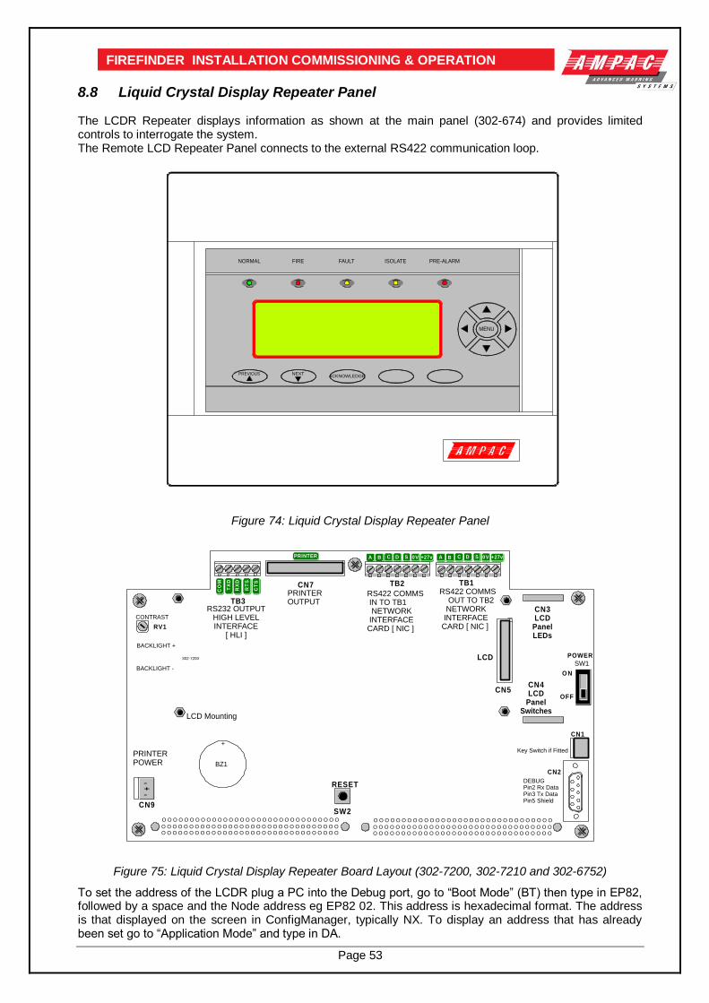
Page 53
FIREFINDER INSTALLATION COMMISSIONING & OPERATION
8.8 Liquid Crystal Display Repeater Panel The LCDR Repeater displays information as shown at the main panel (302-674) and provides limited controls to interrogate the system. The Remote LCD Repeater Panel connects to the external RS422 communication loop.
Figure 74: Liquid Crystal Display Repeater Panel
RS232 OUTPUTHIGH LEVELINTERFACE
[ HLI ]
PRINTEROUTPUT
RS422 COMMS IN TO TB1 NETWORK INTERFACE CARD [ NIC ]
RS422 COMMS OUT TO TB2 NETWORK INTERFACE CARD [ NIC ]
BZ1
RV1
SW2
CN1
TB1TB2CN7
CN2
SW1
CN5
302-7200
+
LCD
OFF
O N
POWER
BACKLIGHT -
BACKLIGHT +
RESET
CONTRAST
DEBUGPin2 Rx DataPin3 Tx DataPin5 Shield
CN3LCD
PanelLEDs
CN4LCD
PanelSwitches
LCD Mounting
SDCBA +27v0V
RX
D
RT
S
CT
S
CO
M
TX
D
SDCBA +27v0V
PRINTERPOWER
O O O O O O O O O O O O O O O O O O O O O O O O O O O O O O O O
O O O O O O O O O O O O O O O O O O O O O O O O O O O O O O O OO O O O O O O O O O O O O O O O O O O O O O O O O O O O O O O O
O O O O O O O O O O O O O O O O O O O O O O O O O O O O O O O O
O O O O O O O O O O O O O O O O O O O O O O O O O O O O O O O OO O O O O O O O O O O O O O O O O O O O O O O O O O O O O O O O
TB3
PRINTER
CN9
-+-
Key Switch if Fitted
Figure 75: Liquid Crystal Display Repeater Board Layout (302-7200, 302-7210 and 302-6752)
To set the address of the LCDR plug a PC into the Debug port, go to “Boot Mode” (BT) then type in EP82, followed by a space and the Node address eg EP82 02. This address is hexadecimal format. The address is that displayed on the screen in ConfigManager, typically NX. To display an address that has already been set go to “Application Mode” and type in DA.
MENU
PREVIOUS NEXTACKNOWLEDGE
PRE-ALARMISOLATEFAULTFIRENORMAL

Page 54
FIREFINDER INSTALLATION COMMISSIONING & OPERATION
9 FireFinderTM Operation
9.1 The Control Panel
EARTH FAULT
TEST MODE
SYSTEM FAULT
SUPPLY FAULT
POWER ON
PRE-ALARM
AUX ALARM
WARNINGSYS FAULT
FinderT M
Fire
WARNING SYSISOLATE
EXTERNAL BELLISOLATE
PREVIOUS NEXTACKNOWLEDGE ISOLATERESET
ISOLATED
ALARM
FAULT
AUXILIARYFAULT / ISOLATE
FAULTOUTPUT ISOLATE
AIFACTIVE
DE-ISOLATE LOOP 1ABC
2DEF GHI
3
SENSOR JKL4
MNO5
PQRS6
ZONE TUV7 8
WXYZ9
SYMB
TO 0SPACE ENTERDISPLAY FUNCTIONMENU
CANCEL ENTRY
FIREFIGHTER FACILITY
FIREFINDER 15/1/2004 14:00:00AMPAC
PH: 08 9242 3333SYSTEM IS NORMAL
1
2
3
4
5 6 7 8 9 10
11
12
13
14
15
16
17
18
19
20
21
22
23
24
25
26
27
28 29
30
31
32
33
34
Figure 76: The FireFinder™ Control Panel
The following describes the function of italically numbered keys above.
1. ALARM
(Red) This LED will flash if any unacknowledged alarms are present on the system. If all the alarms have been acknowledged it will light steady.
2. FAULT
(Yellow) This LED will light steady if there are any faults on the system, EG. loop faults, module faults, device faults etc.
3. ISOLATED
(Yellow) This LED will light steady if any detectors, devices or zones in the system have been isolated.
4.
EXTERNAL BELLISOLATE
(Yellow) Pressing this button will isolate any bells connected to the fire panel If the bell is isolated the LED will be illuminated. Pressing again will de-isolate the bell.
5.
WARNING SYSISOLATE
(Yellow) Pressing this button will isolate the fire panel output to the Warning System if it is connected to one. If the Warning System is isolated the LED just above the button will light steady. Pressing the button again will de-isolate the Warning System output.
6.
PREVIOUS
Previous is used for scrolling backwards through the displayed alarms, faults, or isolates.

Page 55
FIREFINDER INSTALLATION COMMISSIONING & OPERATION
7.
NEXT
Next is used for scrolling forwards through alarms, faults, or isolates on the LCD.
8. ACKNOWLEDGE
Pressing this key will acknowledge an alarm currently displayed on the LCD. It will also silence the panel buzzer, which sounds whenever there is an alarm (optional) or fault.
9. RESET
Pressing this key will reset the panel, clearing any acknowledged alarms and taking the LCD display back to its default screen, unless there are any uncleared faults or isolated devices, these will continue to be displayed.
10. ISOLATE
This key is used to isolate individual or groups of detectors, devices or zones.
11. POWER ON
(Green) This LED will light when the mains power is turned on.
12. PRE-ALARM
(Red) This LED will light when a sensor/detector is in the pre-alarm state.
13. AUX ALARM
(Yellow) This LED will light when the auxiliary alarm output has been activated.
14. WARNINGSYS FAULT (Yellow) When a warning system is connected to the fire panel, this LED will
light if the connection to the warning system becomes faulty.
15. SUPPLY FAULT
(Yellow) This LED will light when there is a fault on the power supply. The following conditions constitute a fault.
The output voltage is too low (less than 26.5V )
The output voltage is too high (greater than 28V )
The battery is not connected properly.
16. EARTH FAULT
(Yellow) This LED will light if there is an incorrect earth on any of the signal cables of the system.
17. SYSTEM FAULT
(Yellow) This LED will light if the main system CPU is in fault.
18. TEST MODE
(Yellow) This LED will light when the panel is in any of the test modes.
19. DE-ISOLATE
If a detector currently displayed on the LCD has been isolated, pressing this key will de-isolate it.
20.
FAULTOUTPUT ISOLATE (Yellow) Pressing this button will isolate the fault output relay on the brigade
board. If the FOI is isolated the associated LED will light. Pressing the button again will de-isolate the FOI relay.
21.
AUXILIARYFAULT / ISOLATE (Yellow) Pressing this button will isolate the auxiliary output relay on the brigade
board. If the auxiliary fault / isolate is isolated the associated LED will light steady. Pressing the button again will de-isolate the auxiliary fault / isolate relay. The auxiliary output line is monitored, should it go into fault, the LED will flash.
22.
AIFACTIVE (Yellow) Pressing this button will activate the Alarm Investigation Facility. The
LED just above the switch shall turn on.

Page 56
FIREFINDER INSTALLATION COMMISSIONING & OPERATION
23. LOOP
Press this key followed by a number to select the loop you wish to access eg LOOP 4.
24. SENSOR
After selecting the Loop number using the LOOP key, press this key to enter the sensor number for the device you wish to interrogate.
25. ZONE
Press this key followed by a number eg ZONE 4 to select the required zone
26. DISPLAY
Press this key after selecting the Zone number or the Loop and Sensor numbers to display the state of the device.
27.
8WXYZ
These keys are used to navigate around the panel’s menus and enter data. If you are entering a descriptor, or some other data that contains characters as well as numbers, pressing the keys multiple times will scroll through the available letters written on the button, in sequence. Eg 1,A,B,C.
28. TO
Use this key to access a range of devices. Eg, 2 TO
7.
29. ENTER
You will be prompted to press the ENTER key at certain times when using the panel, to enter data.
30. CANCEL ENTRY
The CANCEL ENTRY key is used to delete any data in the current field or return to the previously displayed menu.
31. These are used to move the cursor back and forth when entering data in a field.
32. These are used to move between fields when entering data.
33. FUNCTIONMENU
Pressing the MENU key will display the main menu on the LCD. Similarly pressing the FUNCTION key will display the function menu on the LCD.
34. LCD DISPLAY - This screen can be configured with the servicing companies name and phone number. It also displays the current date, time and that the system is normal (no faults and alarms). If there are any faults or alarms the LCD will display the device in question, if multiple detectors or
zones are not in their normal state, the
PREVIOUS
and
NEXT
keys are used to scroll through them.
FireFinder 20/1/2004 13.21.15 SERVICED BY YOUR COMPANY
PH: 09 9999 9999 SYSTEM IS NORMAL
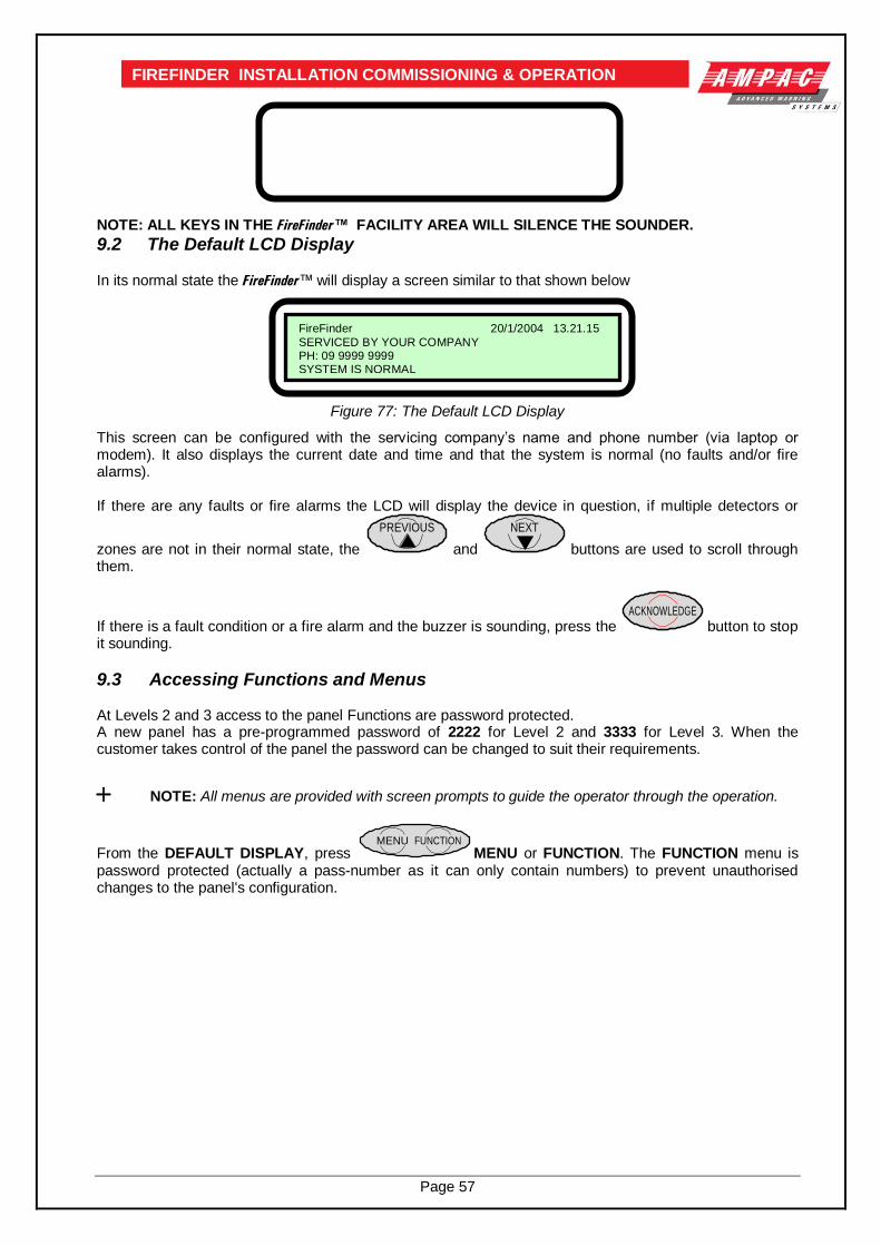
Page 57
FIREFINDER INSTALLATION COMMISSIONING & OPERATION
NOTE: ALL KEYS IN THE FireFinder™ FACILITY AREA WILL SILENCE THE SOUNDER.
9.2 The Default LCD Display
In its normal state the FireFinder™ will display a screen similar to that shown below
Figure 77: The Default LCD Display
This screen can be configured with the servicing company’s name and phone number (via laptop or modem). It also displays the current date and time and that the system is normal (no faults and/or fire alarms). If there are any faults or fire alarms the LCD will display the device in question, if multiple detectors or
zones are not in their normal state, the
PREVIOUS
and
NEXT
buttons are used to scroll through them.
If there is a fault condition or a fire alarm and the buzzer is sounding, press the ACKNOWLEDGE
button to stop it sounding.
9.3 Accessing Functions and Menus At Levels 2 and 3 access to the panel Functions are password protected. A new panel has a pre-programmed password of 2222 for Level 2 and 3333 for Level 3. When the customer takes control of the panel the password can be changed to suit their requirements.
NOTE: All menus are provided with screen prompts to guide the operator through the operation.
From the DEFAULT DISPLAY, press FUNCTIONMENU
MENU or FUNCTION. The FUNCTION menu is password protected (actually a pass-number as it can only contain numbers) to prevent unauthorised changes to the panel's configuration.
FireFinder 20/1/2004 13.21.15
SERVICED BY YOUR COMPANY PH: 09 9999 9999 SYSTEM IS NORMAL
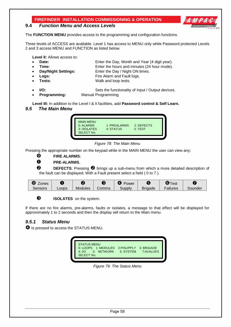
Page 58
FIREFINDER INSTALLATION COMMISSIONING & OPERATION
9.4 Function Menu and Access Levels The FUNCTION MENU provides access to the programming and configuration functions. Three levels of ACCESS are available. Level 1 has access to MENU only while Password protected Levels 2 and 3 access MENU and FUNCTION as listed below.
Level II: Allows access to:
Date: Enter the Day, Month and Year (4 digit year).
Time: Enter the hours and minutes (24 hour mode).
Day/Night Settings: Enter the Day / Night ON times.
Logs: Fire Alarm and Fault logs.
Tests: Walk and loop tests.
I/O: Sets the functionality of Input / Output devices.
Programming: Manual Programming
Level III: In addition to the Level I & II facilities, add Password control & Self Learn.
9.5 The Main Menu
Figure 78: The Main Menu
Pressing the appropriate number on the keypad while in the MAIN MENU the user can view any;
FIRE ALARMS;
PRE-ALARMS,
DEFECTS; Pressing brings up a sub-menu from which a more detailed description of
the fault can be displayed. With a Fault present select a field ( 0 to 7 ).
Zones
Sensors
Loops
Modules
Comms
Power
Supply
Brigade
Test
Failures
Sounder
ISOLATES on the system.
If there are no fire alarms, pre-alarms, faults or isolates, a message to that effect will be displayed for approximately 1 to 2 seconds and then the display will return to the Main menu.
9.5.1 Status Menu
Is pressed to access the STATUS MENU.
Figure 79: The Status Menu
MAIN MENU
0: ALARMS 1 :PREALARMS 2: DEFECTS 3: ISOLATES 4: STATUS 5 :TEST SELECT No.
STATUS MENU 0: LOOPS 1 :MODULES 2:P/SUPPLY 3: BRIGADE
4: I/O 5: NETWORK 6 :SYSTEM 7:AVALUES SELECT No.

Page 59
FIREFINDER INSTALLATION COMMISSIONING & OPERATION From the STATUS MENU the status of all of the system components and settings listed below can be displayed.
Press
Loops: Enter the loop number and the LCD will display its status, eg normal, type of fault etc.
Modules: Select the type of module (Slave or LED Mimic ) then enter the module number and
the LCD will display the type, the software version and its status.
Supply: This menu item will display the charger voltage, whether or not the power supply is in
fault, if the battery is correctly fitted and if Mains power is present.
Brigade: This will display the status of all of the outputs on the Brigade Output Board. Eg. Bell, Aux, DSW, Warn, Fault, Alarm, Isol, Bfail, Vmon & Brigade Status
I/O: The LCD will display the status of an input or output in a panel or on a loop.
Enter i) the I/O controller number then the input or output on that controller or, ii) the loop, sensor and output number on that device. Once entered the LCD will display if it is configured, a description of what that input or output does and its current state.

Page 60
FIREFINDER INSTALLATION COMMISSIONING & OPERATION Network:
Is pressed to access NETWORK STATUS.
Figure 80: Display Network Status
Network Points:
Figure 81: Display Network Points
Network Points Screens are Press or or
Status Power Supply Brigade
Displays Displays Displays Select network point
Charger volts
Operational
Eg. Loop number Battery Detected Non- Op Mains OK
Remote Slave Modules:
Select from Network Status Remote Slave Modules then Module number then ENTER .
Figure 82: Display Remote Module Status
Remote External LED Mimic Modules:
Select from Network Status Remote External LED Mimic Modules then NP number then ENTER then
External LED Mimic number then ENTER
DISPLAY NETWORK STATUS
0: NETWORK POINTS 1: REMOTE SLAVE MODULES 2; REMOTE EXTERNAL LED MIMIC MODULES SELECT NO.
Apollo Loop No: 1 TYPE: APOLLO LOOP NO: 1 VER: 6 NP: 1 MOD: 1 STAT : NORMAL
REMOTE MODULE STATUS
DISPLAY NETWORK POINTS 0: STATUS 1: POWER SUPPLY 2: BRIGADE
SELECT NO.

Page 61
FIREFINDER INSTALLATION COMMISSIONING & OPERATION System:
Is pressed to access SYSTEM STATUS.
Figure 83: System Status
A Values:
Is pressed to access AVALUES. Enter Loop number then ENTER then Sensor number then
ENTER
Figure 84: Analogue Values
9.5.2 Testing Menu
Press;
to access the TESTING MENU. From here the following can be tested:
Figure 85: The Testing Menu
Alarm Test Press
: Alarm tests either a zone or a sensor or a range of zones or sensors.
(This test will force a sensor to go to the Alarm State or a conventional zone to a simulated Alarm State)
Fault Test Press
: Fault tests either a zone or a sensor or a range of zones or sensors.
(This test will force a sensor to go to the Fault State or a conventional zone to a simulated Fault State)
NOTE: Once the above tests have been completed the TEST FAILURE screen will appear. Each
ALARM and FAULT that was detected can be viewed by scrolling through them using the NEXT and PREVIOUS buttons.
Lamp Test Press
: Will flash the LED’s in sequence on the front panel and illuminate the various segments on
the LCD display.
TESTING MENU 0: ALARM 1: FAULT 2: LAMP
SELECT NO.
SYSTEM STATUS ALARMS: 0000 PRE-ALARMS: 0000 ISOLATES:0000
ZONE / SENSOR FAULTS: 0000 MODULE FAULTS: 00 LOOP FAULTS: 00 VERSION.: 6.0. NZ4512
Loop 1 sensor 1 SMOKE L1 S1 Z2 STAT : NORMAL AVALUE : 25 MODE: 0 I : 000 O : 000

Page 62
FIREFINDER INSTALLATION COMMISSIONING & OPERATION
9.6 Function Menu ( Level 2 / 3 ) The Function Menu provides access to the configuration and programming. These Functions are protected by a password (actually a pass-number as it can only contain numbers) to prevent unauthorised tampering with the panel's configuration. A new panel will have the password 2222 for Level 2 and 3333 for level 3 already programmed so that you can enter your own. To get to the Functions Menu press the “FUNCTION” key while the panel is on the Default Display and then enter the password.
Figure 86 The Level III Functions Menu
9.6.1 Setting the Function Date Facility
Select FUNCTION . A prompt will ask for a PASSWORD if the control panel is not currently active. Using
the keypad key in the Level 2 or 3 PASSWORD and press ENTER .
Press
to select the set DATE SCREEN. The prompt will ask for the date to be entered in this format,
DD/MM/YYYY ( EG 18/09/2001 ), key in and press ENTER . The screen will then return to the
MAIN FUNCTIONS MENU.
9.6.2 Setting the Function Time Facility
Press
then in the following format key in the time, HH:MM using the 24 hour mode. Press ENTER
and the screen will return to the MAIN FUNCTIONS MENU.
9.6.3 Setting the Function Daynight Facility
Press
The DAY-NIGHT SETTINGS screen will appear.
Press
to enter the DAY ON time then ENTER and,
to enter the NIGHT ON time then ENTER .
to ENABLE / DISABLE then ENTER .
For this Function to have control it must be ENABLED, press Re-pressing will toggle to DISABLE.
LEVEL III MAIN FUNCTIONS
0: DATE 1: TIME 2: DAY/NIGHT SETTINGS 3: LOGS 4: TESTS 5: I/O 6: PROG 7: PASSWORD SELECT No.

Page 63
FIREFINDER INSTALLATION COMMISSIONING & OPERATION
9.6.4 Function Logs Facility Press and the EVENT LOG MENU will be displayed.
The LOGS MENU allows the operator to select and view the events that have occurred of all;
Press
ALARM
FAULT
ISOLATE
SYSTEM
The date and time of the ALARM, FAULT or ISOLATE as well as the device information will be displayed. The SYSTEM screen displays events and watchdog activity. This screen also allows the operator to select two other facilities;
Press
PRINT ENTRY will print out the displayed information if a printer is installed,
SHOW OPTIONS allows the operator to select how the Logs are viewed. Press or Press
to VIEW BY ENTRY NUMBER or to VIEW BY DATE. In each case the screen will
ask for the appropriate information ( ENTRY NUMBER or DATE ) to be entered before anything can be displayed.
NOTE: it is possible to scroll through the alarms by using
PREVIOUS
NEXT
9.6.5 The Function Test Facility Press
TESTS prompts the operator to select the type of test they wish to perform, that is either the
WALK test or the LOOP test. Press
WALK TEST; the operator will again be prompted to press either
ZONE test or, SENSOR test.
Press
ZONE WALK TEST MENU;
This screen requires the operator to select a Zone or number of Zones to be tested, that is enter the
Zone number press ENTER or enter the Zone number press TO then the next highest
Zone number to be tested EG. 2 TO 7 then ENTER.
The TEST MODE LED will be illuminated for the duration of the test and the test will run until the operator RESETS the system.
Press
SENSOR WALK TEST MENU
This screen requires the operator to select a Zone and then a Sensor or number of Sensors (
using the TO key ) to be tested then pressing ENTER to start the test.
The TEST MODE LED will be illuminated for the duration of the test and the test will run until the operator RESETS the system.

Page 64
FIREFINDER INSTALLATION COMMISSIONING & OPERATION Press
LOOP TEST requires the operator to select a LOOP for DIAGNOSTIC TESTING
Entering the LOOP number and pressing ENTER will initiate the DIAGNOSTIC TEST.
NOTE: The LEDs on the Brigade Board will indicate which leg is being tested.
The tests displayed are;
TESTING SIDE A IDENTIFING DEVICES on SIDE A, and
TESTING SIDE B IDENTIFING DEVICES on SIDE B. Once the testing is completed the final screen will display the number of devices found and tested on the LOOP and a Reset is requested to return the system to normal.
NOTE: If the data is not entered within 2 minutes the screen will time out and return to the
DEFAULT SCREEN.
9.6.6 Function Manual I/O Control Press
to display the Manual I/O Control menu
Figure 87: The Manual I/O Control Menu
Manual I/O control allows the technician to turn ON or Off inputs and outputs off a device to facilitate testing or isolation of plant during maintenance. Removal of manual control returns control to the panel or loop.
Press
Input Selected:
Press
IN A PANEL: Enter the I/O Controller number then the input number . This will
display the description for the input and its current state, you can then turn the input ON or OFF or remove manual control.
ON A LOOP: Enter the loop number , the sensor number and the input number.
This will display the description for the input and its current state, you can then turn the input ON or OFF or remove manual control.
Remove All Manual Input Control: Will remove all manual input control.
Output Selected: Same sequences as above for inputs but
substitute outputs for inputs.
Remove All Manual Control Selected: Globally removes all manual control.
MANUAL I/O CONTROL 0: INPUT 1 :OUTPUT 2: REMOVE ALL MANUAL CONTROL SELECT NO.
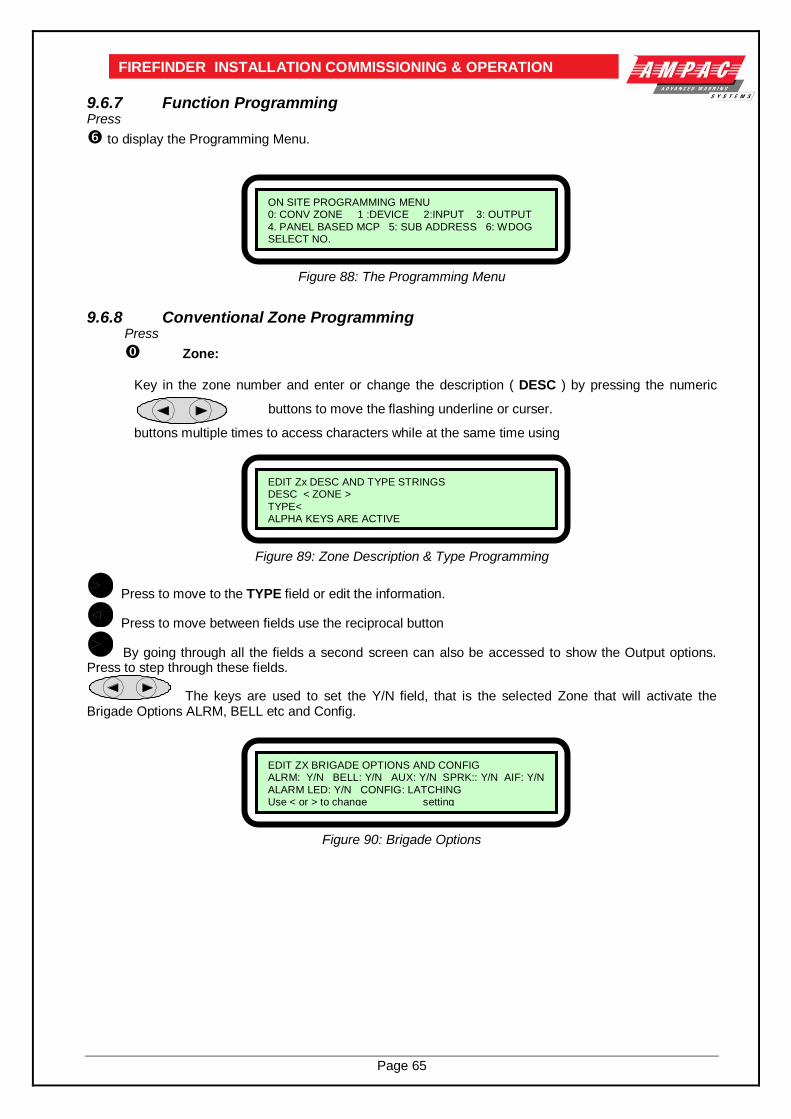
Page 65
FIREFINDER INSTALLATION COMMISSIONING & OPERATION
9.6.7 Function Programming Press
to display the Programming Menu.
Figure 88: The Programming Menu
9.6.8 Conventional Zone Programming Press
Zone:
Key in the zone number and enter or change the description ( DESC ) by pressing the numeric
buttons multiple times to access characters while at the same time using
Figure 89: Zone Description & Type Programming
Press to move to the TYPE field or edit the information.
Press to move between fields use the reciprocal button
By going through all the fields a second screen can also be accessed to show the Output options. Press to step through these fields.
The keys are used to set the Y/N field, that is the selected Zone that will activate the
Brigade Options ALRM, BELL etc and Config.
Figure 90: Brigade Options
ON SITE PROGRAMMING MENU 0: CONV ZONE 1 :DEVICE 2:INPUT 3: OUTPUT
4. PANEL BASED MCP 5: SUB ADDRESS 6: WDOG SELECT NO.
EDIT Zx DESC AND TYPE STRINGS DESC < ZONE >
TYPE< ALPHA KEYS ARE ACTIVE
EDIT ZX BRIGADE OPTIONS AND CONFIG ALRM: Y/N BELL: Y/N AUX: Y/N SPRK:: Y/N AIF: Y/N
ALARM LED: Y/N CONFIG: LATCHING Use < or > to change setting
buttons to move the flashing underline or curser.
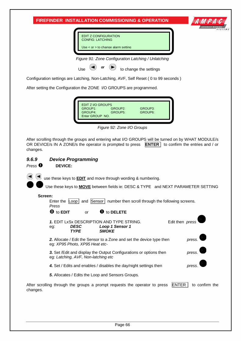
Page 66
FIREFINDER INSTALLATION COMMISSIONING & OPERATION
Figure 91: Zone Configuration Latching / Unlatching
Use or
to change the settings
Configuration settings are Latching, Non-Latching, AVF, Self Reset ( 0 to 99 seconds ) After setting the Configuration the ZONE I/O GROUPS are programmed.
Figure 92: Zone I/O Groups
After scrolling through the groups and entering what I/O GROUPS will be turned on by WHAT MODULE/s
OR DEVICE/s IN A ZONE/s the operator is prompted to press ENTER to confirm the entries and / or
changes.
9.6.9 Device Programming
Press DEVICE:
use these keys to EDIT and move through wording & numbering.
Use these keys to MOVE between fields ie: DESC & TYPE and NEXT PARAMETER SETTING
Screen:
Enter the Loop and Sensor number then scroll through the following screens.
Press
to EDIT or to DELETE
1. EDIT LxSx DESCRIPTION AND TYPE STRING. Edit then press
eg: DESC Loop 1 Sensor 1
TYPE SMOKE
2. Allocate / Edit the Sensor to a Zone and set the device type then press.
eg: XP95 Photo, XP95 Heat etc-
3. Set /Edit and display the Output Configurations or options then press.
eg: Latching, AVF, Non-latching etc
4. Set / Edits and enables / disables the day/night settings then press.
5. Allocates / Edits the Loop and Sensors Groups.
After scrolling through the groups a prompt requests the operator to press ENTER to confirm the
changes.
EDIT Z I/O GROUPS GROUP1: GROUP2: GROUP3:
GROUP4: GROUP5: GROUP6: Enter GROUP NO.
EDIT Z CONFIGURATION CONFIG: LATCHING
Use < or > to change alarm setting
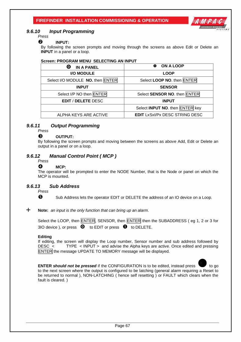
Page 67
FIREFINDER INSTALLATION COMMISSIONING & OPERATION
9.6.10 Input Programming Press
INPUT: By following the screen prompts and moving through the screens as above Edit or Delete an INPUT in a panel or a loop.
Screen: PROGRAM MENU SELECTING AN INPUT
IN A PANEL ON A LOOP
I/O MODULE LOOP
Select I/O MODULE NO. then ENTER Select LOOP NO. then ENTER
INPUT SENSOR
Select I/P NO then ENTER Select SENSOR NO. then ENTER
EDIT / DELETE DESC INPUT
Select INPUT NO. then ENTER key
ALPHA KEYS ARE ACTIVE EDIT LxSxI/Px DESC STRING DESC
9.6.11 Output Programming Press
OUTPUT: By following the screen prompts and moving between the screens as above Add, Edit or Delete an output in a panel or on a loop.
9.6.12 Manual Control Point ( MCP ) Press
MCP: The operator will be prompted to enter the NODE Number, that is the Node or panel on which the MCP is mounted.
9.6.13 Sub Address Press
Sub Address lets the operator EDIT or DELETE the address of an IO device on a Loop.
Note: an input is the only function that can bring up an alarm.
Select the LOOP, then ENTER, SENSOR, then ENTER then the SUBADDRESS ( eg 1, 2 or 3 for
3IO device ), or press to EDIT or press to DELETE.
Editing If editing, the screen will display the Loop number, Sensor number and sub address followed by DESC < TYPE < INPUT > and advise the Alpha keys are active. Once edited and pressing
ENTER the message UPDATE TO MEMORY message will be displayed.
ENTER should not be pressed if the CONFIGURATION is to be edited, instead press
to go to the next screen where the output is configured to be latching (general alarm requiring a Reset to be returned to normal ), NON-LATCHING ( hence self resetting ) or FAULT which clears when the fault is cleared. )

Page 68
FIREFINDER INSTALLATION COMMISSIONING & OPERATION
9.6.14 Watchdog
This Function provides a counter to record any re-initialisation of the processor. If due to a
software failure the panel is automatically reset then the counter will increment by 1 The maximum count is 99 after which the counter resets to 00. Pressing will reset the counter. When the panel is commissioned this counter MUST be reset to 0 as must be the Events Logs.
9.6.15 Self Learn
Self Learn is enabled / disabled in the EEPROM programming. If enabled FireFinder has the
ability to detect extra or missing modules or devices, ( that is devices or modules that have been added or removed ) or there has been a change of the type of module or device.
Note: If a change does occur the FACP will take 30seconds to register the event on the LCD and
illuminate the FAULT LED.
9.6.16 Extra Devices Detected
The FireFinder LCD will indicate extra devices have been detected by displaying the screen below and
the FAULT LED will be illuminated.
Figure 93: Resolving Extra Modules And Devices
To resolve select FUNCTION, enter PASSWORD, press and the screen below will appear
Figure 94:Added Module Or Device
Select ( Selecting presents the PROGRAMMING MENU ) then or (as seen below) then
ENTER to ADD the module or device to the configuration, or skip to resolve the changes manually in the
Programming Menu.
Figure 95: Resolving Extra Modules Or Devices
FIREFINDER 10/2/2004 05:45 EXTRA DEVICES DETECTED GOTO PROGRAMMING MENU TO RESOLVE
SYSTEM IS NOT NORMAL
PROGRAMMING MENU 0: RESOLVE EXTRA MODULES AND DEVICES 1: ON SITE PROGRAMMING
SELECT NO.
0: ADD EXTRA MODULES 1: ADD EXTRA DEVICES
2: DEVICE TYPE MISMATCH 3: MODE MISMATCH SELECT NO.

Page 69
FIREFINDER INSTALLATION COMMISSIONING & OPERATION
9.6.17 Mismatch Detected If a mismatch is detected the Normal Default Screen will change to that shown below. Go to the
Programming Menu and select either Resolve Extra Modules and Devices then ( Device Type ) or
( Mode ) to resolve the mismatch, OR On Site Programming to resolve manually.
Figure 96: Resolving A Mismatch
9.6.18 Function Passwords
Figure 97: The Password Menu
Press
while in the Main Functions menu (if your password gives you access) to display the Password Menu.
Add Password: Enter the new password, then press ENTER . The password is always a
4 digit number.
Delete Password: Enter the password that you want to delete, then press ENTER.
Delete All Passwords: This asks you to confirm that you want to delete all the passwords.
Press ENTER then ENTER again.
9.6.19 Forgotten Passwords If you have forgotten your password,
a. enter 9999 into the password field; b. Take note of the 4 digit password button displayed on the screen; c. contact the AMPAC head office and quote this number; d. a temporary password will be issued to allow access to level 3 functions; e. a new password can now be programmed.
NOTE: The temporary password will become invalid if 9999 is entered again or if the panel is re-powered.
PASSWORD MENU 0: ADD PASSWORD 1 :DELETE PASSWORD
2: DELETE ALL PASSWORDS SELECT NO.
Loop 1 Sensor 6 L1 S6 Z1 STAT: TYPE MISMATCH
ZONE FAULTS 1 OF 1
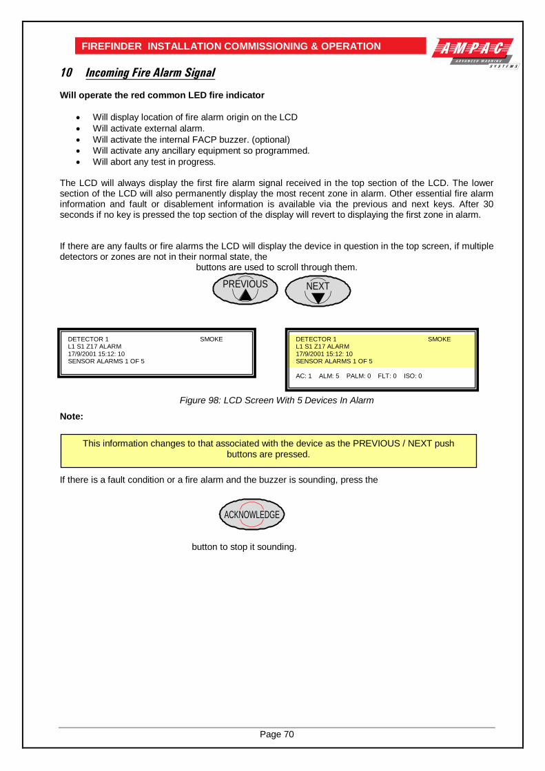
Page 70
FIREFINDER INSTALLATION COMMISSIONING & OPERATION
10 Incoming Fire Alarm Signal Will operate the red common LED fire indicator
Will display location of fire alarm origin on the LCD
Will activate external alarm.
Will activate the internal FACP buzzer. (optional)
Will activate any ancillary equipment so programmed.
Will abort any test in progress.
The LCD will always display the first fire alarm signal received in the top section of the LCD. The lower section of the LCD will also permanently display the most recent zone in alarm. Other essential fire alarm information and fault or disablement information is available via the previous and next keys. After 30 seconds if no key is pressed the top section of the display will revert to displaying the first zone in alarm. If there are any faults or fire alarms the LCD will display the device in question in the top screen, if multiple detectors or zones are not in their normal state, the
buttons are used to scroll through them.
Figure 98: LCD Screen With 5 Devices In Alarm
Note: If there is a fault condition or a fire alarm and the buzzer is sounding, press the
button to stop it sounding.
This information changes to that associated with the device as the PREVIOUS / NEXT push buttons are pressed.
DETECTOR 1 SMOKE L1 S1 Z17 ALARM 17/9/2001 15:12: 10 SENSOR ALARMS 1 OF 5
DETECTOR 1 SMOKE L1 S1 Z17 ALARM 17/9/2001 15:12: 10 SENSOR ALARMS 1 OF 5 AC: 1 ALM: 5 PALM: 0 FLT: 0 ISO: 0
PREVIOUS NEXT
ACKNOWLEDGE
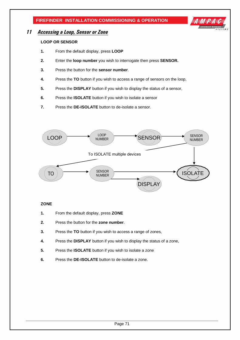
Page 71
FIREFINDER INSTALLATION COMMISSIONING & OPERATION
11 Accessing a Loop, Sensor or Zone
LOOP OR SENSOR
1. From the default display, press LOOP
2. Enter the loop number you wish to interrogate then press SENSOR.
3. Press the button for the sensor number.
4. Press the TO button if you wish to access a range of sensors on the loop,
5. Press the DISPLAY button if you wish to display the status of a sensor,
6. Press the ISOLATE button if you wish to isolate a sensor
7. Press the DE-ISOLATE button to de-isolate a sensor.
ZONE
1. From the default display, press ZONE
2. Press the button for the zone number.
3. Press the TO button if you wish to access a range of zones,
4. Press the DISPLAY button if you wish to display the status of a zone,
5. Press the ISOLATE button if you wish to isolate a zone
6. Press the DE-ISOLATE button to de-isolate a zone.
To ISOLATE multiple devices
LOOPLOOP
NUMBER SENSORSENSORNUMBER
TOSENSORNUMBER
DISPLAY
ISOLATE
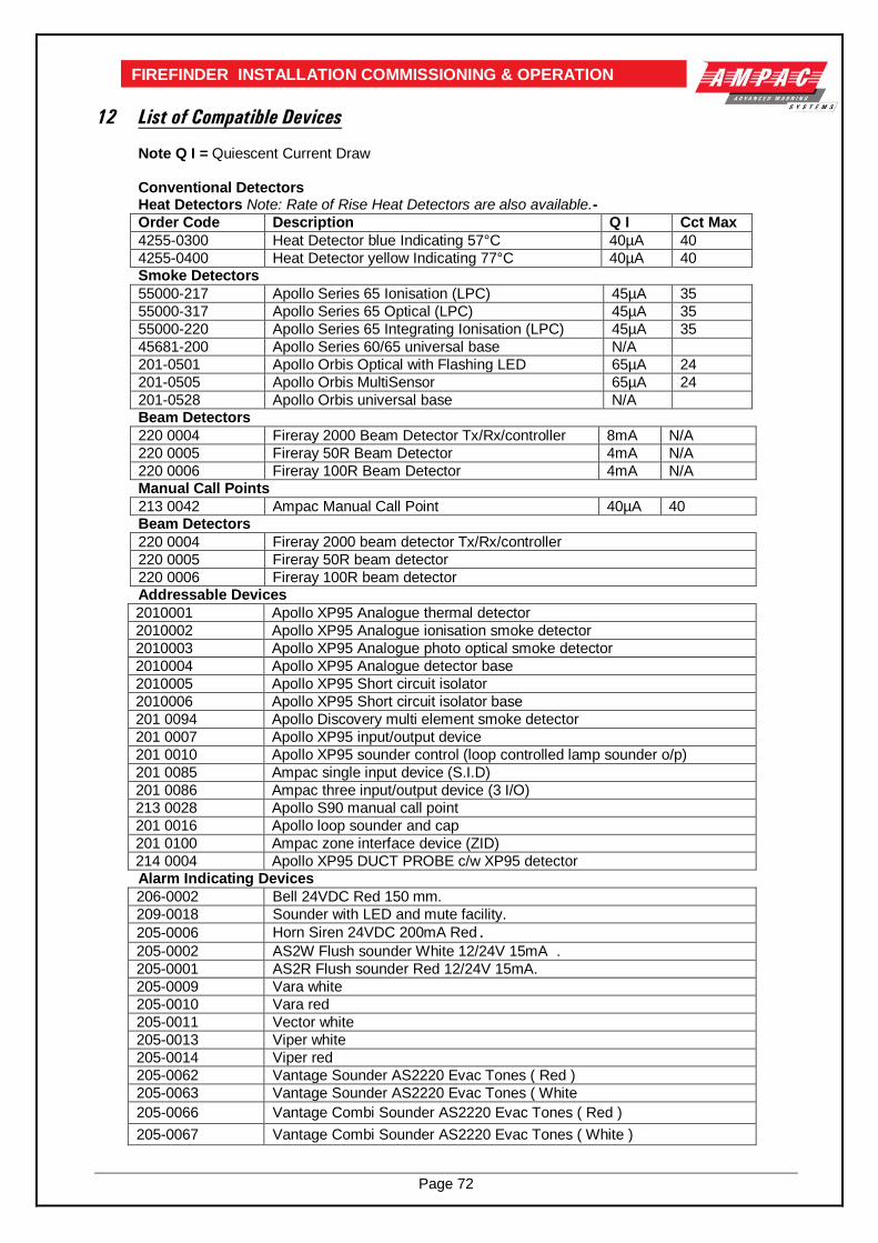
Page 72
FIREFINDER INSTALLATION COMMISSIONING & OPERATION
12 List of Compatible Devices
Note Q I = Quiescent Current Draw
Conventional Detectors Heat Detectors Note: Rate of Rise Heat Detectors are also available.-
Order Code Description Q I Cct Max
4255-0300 Heat Detector blue Indicating 57°C 40µA 40
4255-0400 Heat Detector yellow Indicating 77°C 40µA 40 Smoke Detectors
55000-217 Apollo Series 65 Ionisation (LPC) 45µA 35
55000-317 Apollo Series 65 Optical (LPC) 45µA 35
55000-220 Apollo Series 65 Integrating Ionisation (LPC) 45µA 35
45681-200 Apollo Series 60/65 universal base N/A
201-0501 Apollo Orbis Optical with Flashing LED 65µA 24
201-0505 Apollo Orbis MultiSensor 65µA 24
201-0528 Apollo Orbis universal base N/A Beam Detectors
220 0004 Fireray 2000 Beam Detector Tx/Rx/controller 8mA N/A
220 0005 Fireray 50R Beam Detector 4mA N/A
220 0006 Fireray 100R Beam Detector 4mA N/A Manual Call Points
213 0042 Ampac Manual Call Point 40µA 40 Beam Detectors
220 0004 Fireray 2000 beam detector Tx/Rx/controller
220 0005 Fireray 50R beam detector
220 0006 Fireray 100R beam detector Addressable Devices
2010001 Apollo XP95 Analogue thermal detector
2010002 Apollo XP95 Analogue ionisation smoke detector
2010003 Apollo XP95 Analogue photo optical smoke detector
2010004 Apollo XP95 Analogue detector base
2010005 Apollo XP95 Short circuit isolator
2010006 Apollo XP95 Short circuit isolator base
201 0094 Apollo Discovery multi element smoke detector
201 0007 Apollo XP95 input/output device
201 0010 Apollo XP95 sounder control (loop controlled lamp sounder o/p)
201 0085 Ampac single input device (S.I.D)
201 0086 Ampac three input/output device (3 I/O)
213 0028 Apollo S90 manual call point
201 0016 Apollo loop sounder and cap
201 0100 Ampac zone interface device (ZID)
214 0004 Apollo XP95 DUCT PROBE c/w XP95 detector Alarm Indicating Devices
206-0002 Bell 24VDC Red 150 mm.
209-0018 Sounder with LED and mute facility.
205-0006 Horn Siren 24VDC 200mA Red.
205-0002 AS2W Flush sounder White 12/24V 15mA .
205-0001 AS2R Flush sounder Red 12/24V 15mA.
205-0009 Vara white
205-0010 Vara red
205-0011 Vector white
205-0013 Viper white
205-0014 Viper red
205-0062 Vantage Sounder AS2220 Evac Tones ( Red )
205-0063 Vantage Sounder AS2220 Evac Tones ( White
205-0066 Vantage Combi Sounder AS2220 Evac Tones ( Red )
205-0067 Vantage Combi Sounder AS2220 Evac Tones ( White )

Page 73
FIREFINDER INSTALLATION COMMISSIONING & OPERATION
13 Certification Information
The FireFinder™ is designed and manufactured by:
AMPAC TECHNOLOGIES PTY LTD
7 Ledgar Road
Balcatta 6021
Western Australia
PH: 61-8-9201 6100
FAX: 61-8-9201 6101
Manufactured to: NZS4512 2003
OPUS Certificate of Compliance Number:
Equipment Serial Number:
Date of Manufacture:

Page 74
FIREFINDER INSTALLATION COMMISSIONING & OPERATION
14 Troubleshooting Chart
Problem Solution
No Mains Power Check mains Fuse
Supply fault LED illuminated
Check output voltage is set to 27.6V.
Low = (less than 26.5V )
High = (greater than 28V )
Check the battery has been connected properly
Earth Fault LED illuminated Check all input and output cabling and wiring assemblies for short to ground
System Fault LED illuminated Ensure correct software is installed
Check all connections for loose wiring
Warning System Fault LED illuminated Check correct E.O.L is fitted (10K)
Check wiring is connected correctly
Maintenance Alarm cleared but FireFinder™ still displays
Maintenance Alarm Panel needs to be reset
LCD displays LOOP (number) open circuit Check in and out legs are connected correctly at the loop termination board
Unable to clear an O/C or S/C on a loop You must perform a loop test to clear the fault. This is a level 1 function.
Communication Loop not working
Check for correct software installed in all communication boards.
Check LCD at Main controller. This may identify where there is a break in the communication line
Can not access Function menu Incorrect Password entered
Forgotten password Ring AMPAC and directions will be given to provide you with a temporary code
An Analogue Fault occurs when using a Zone Monitor to monitor a switch.
A 1.8k Ohm resistor must be placed in series with the switch contracts.
Sounder Fault Make sure you have a 10K Ohm EOL resistor fitted and a diode (1N4004) in series with the sounder
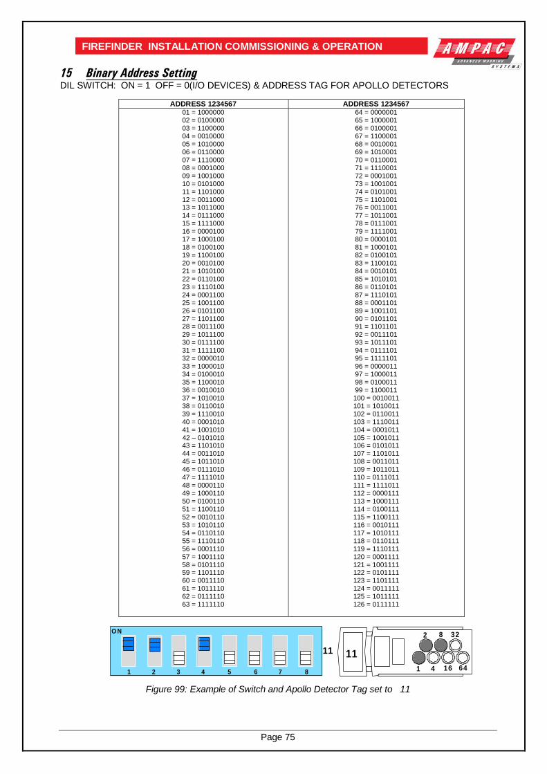
Page 75
FIREFINDER INSTALLATION COMMISSIONING & OPERATION
15 Binary Address Setting DIL SWITCH: ON = 1 OFF = 0(I/O DEVICES) & ADDRESS TAG FOR APOLLO DETECTORS
ADDRESS 1234567 ADDRESS 1234567 01 = 1000000 02 = 0100000 03 = 1100000 04 = 0010000 05 = 1010000 06 = 0110000 07 = 1110000 08 = 0001000 09 = 1001000 10 = 0101000 11 = 1101000 12 = 0011000 13 = 1011000 14 = 0111000 15 = 1111000 16 = 0000100 17 = 1000100 18 = 0100100 19 = 1100100 20 = 0010100 21 = 1010100 22 = 0110100 23 = 1110100 24 = 0001100 25 = 1001100 26 = 0101100 27 = 1101100 28 = 0011100 29 = 1011100 30 = 0111100 31 = 1111100 32 = 0000010 33 = 1000010 34 = 0100010 35 = 1100010 36 = 0010010 37 = 1010010 38 = 0110010 39 = 1110010 40 = 0001010 41 = 1001010 42 – 0101010 43 = 1101010 44 = 0011010 45 = 1011010 46 = 0111010 47 = 1111010 48 = 0000110 49 = 1000110 50 = 0100110 51 = 1100110 52 = 0010110 53 = 1010110 54 = 0110110 55 = 1110110 56 = 0001110 57 = 1001110 58 = 0101110 59 = 1101110 60 = 0011110 61 = 1011110 62 = 0111110 63 = 1111110
64 = 0000001 65 = 1000001 66 = 0100001 67 = 1100001 68 = 0010001 69 = 1010001 70 = 0110001 71 = 1110001 72 = 0001001 73 = 1001001 74 = 0101001 75 = 1101001 76 = 0011001 77 = 1011001 78 = 0111001 79 = 1111001 80 = 0000101 81 = 1000101 82 = 0100101 83 = 1100101 84 = 0010101 85 = 1010101 86 = 0110101 87 = 1110101 88 = 0001101 89 = 1001101 90 = 0101101 91 = 1101101 92 = 0011101 93 = 1011101 94 = 0111101 95 = 1111101 96 = 0000011 97 = 1000011 98 = 0100011 99 = 1100011 100 = 0010011 101 = 1010011 102 = 0110011 103 = 1110011 104 = 0001011 105 = 1001011 106 = 0101011 107 = 1101011 108 = 0011011 109 = 1011011 110 = 0111011 111 = 1111011 112 = 0000111 113 = 1000111 114 = 0100111 115 = 1100111 116 = 0010111 117 = 1010111 118 = 0110111 119 = 1110111 120 = 0001111 121 = 1001111 122 = 0101111 123 = 1101111 124 = 0011111 125 = 1011111 126 = 0111111
O N
11
1 2 3 4 5 6 7 8 1
2
4
8
16
32
64
11
Figure 99: Example of Switch and Apollo Detector Tag set to 11

Page 76
FIREFINDER INSTALLATION COMMISSIONING & OPERATION
16 Glossary of Terms
ACF : ANCILLARY CONTROL FACILITY
ACKD : ACKNOWLEDGED
AHU : AIR HANDLING UNIT
ALM : ALARM
AVF : ALARM VERIFICATION FACILITY
AZF : ALARM ZONE FACILITY
AZC : ALARM ZONE CIRCUIT
C : RELAY COMMON CONTACT (WIPER)
CIC : CONTROLLER INTERFACE CARD
CN : CONNECTOR
CPU : COMMON PROCESSOR UNIT
VD : DIRECT CURRENT VOLTS
DGP : DATA GATHERING POINT
EARTH : BUILDING EARTH
EOL : END OF LINE
FACP : FIRE ALARM CONTROL PANEL
FDS : FIRE DETECTION SYSTEM
FIP : FIRE INDICATOR PANEL
FLT : FAULT
GND : GROUND (0 VOLTS) NOT EARTH
I/O : INPUT/OUTPUT
LCD : LIQUID CRYSTAL DISPLAY
MAF : MASTER ALARM FACILITY
MCP : MANUAL CALL POINT
MOV : METAL OXIDE VARISTOR (TRANSIENT PROTECTION)
NIC : NETWORK INTERFACE CARD
N/C : NORMALLY CLOSED RELAY CONTACTS
N/O : NORMALLY OPEN RELAY CONTACTS
PCB : PRINTED CIRCUIT BOARDS
P/S : POWER SUPPLY
PSM : POWER SUPPLY MODULE
REM : REMOTE
SPOT : SINGLE PERSON OPERATING TEST
TB : TERMINAL BLOCK

Page 77
FIREFINDER INSTALLATION COMMISSIONING & OPERATION
17 Definitions Addressable system - a fire alarm and detection system that contains addressable alarm zone facilities or addressable control devices.
Alarm Verification Facility (AVF) - that part of the FACP that provides an automatic resetting function for spurious alarm signals so that they will not initiate master alarm facility (MAF), or ACF functions inadvertently. Using the configuration manager prior to downloading to the FireFinder™ sets this option
Alarm zone - the specific portion of a building or complex identified by a particular alarm zone facility.
Alarm Zone Circuit (AZC) - the link or path that carries signals from an actuating device(s) to an alarm zone facility(s).
Alarm Zone Facility (AZF) - that part of the control and indicating equipment that registers and indicates signals (alarm and fault) received from its alarm zone circuit. It also transmits appropriate signals to other control and indicating facilities.
Alert signal - an audible signal, or combination of audible and visible signals, from an emergency warning system to alert nominated personnel as necessary to commence prescribed actions.
Ancillary Control Facility (ACF) - that portion of the control and indicating equipment that on receipt of a signal initiates predetermined actions in external ancillary devices.
Ancillary equipment - remote equipment connected to FACP.
Ancillary relay - relay within FACP to operate ancillary equipment.
Ancillary output - output for driving ancillary equipment.
Approved and approval - approved by, or the approval of, the Regulatory Authority concerned.
Card-detect link - a link on a module connector to indicate the disconnection of the module.
Conventional System - is a fire detection system using a dedicated circuit for each alarm zone.
Distributed system - a fire alarm and detection system where sections of the control and indicating equipment are remotely located from the fire indicator panel or where sub-indicator panel(s) communicate with a main fire indicator panel.
Factory connections - connections made during manufacture and should not require any field alterations.
Field connections - connections made to FACP or ancillary equipment at the project during installation.
Fire alarm system - an arrangement of components and apparatus for giving an audible, visible, or other perceptible alarm of fire, and which may also initiate other action.
Fire detection system - an arrangement of detectors and control and indicating equipment employed for automatically detecting fire and initiating other action as arranged.
Fire Alarm Control Panel (FACP) - a panel on which is mounted an indicator or indicators together with associated equipment for the fire alarm or sprinkler system.
Indicating equipment - the part of a fire detection and or alarm system, which provides indication of any warning signals (alarm and fault), received by the control equipment.
Interface - The interconnection between equipment that permits the transfer of data.
Master Alarm Facility (MAF) - that part of the control and indicating equipment which receives alarm and fault signals from any alarm zone facility and initiates the common signal (alarm and/or fault) for transmission to the fire control station. Bells and other ancillary functions may be initiated from this facility.
Power Supply – circuitry which supplies all voltages necessary for operation of the FACP.
Regulatory Authority - an authority administering Acts of Parliament or Regulations under such Acts.

Page 78
FIREFINDER INSTALLATION COMMISSIONING & OPERATION
18 Quick Reference Guides
FireFinder™
MA
IN M
EN
U O
PT
ION
S
ME
NU
KE
Y /
FU
NC
TIO
N K
EY
(
TO
EN
TE
R M
EN
U /
TO
FU
NC
TIO
N M
EN
U )
AL
AR
MS
( D
ISP
LA
Y A
LA
RM
S )
PR
EA
LA
RM
S (
DIS
PL
AY
PR
E-A
LA
RM
S )
FA
UL
TS
( D
ISP
LA
Y F
AU
LT
S O
F S
EL
EC
TE
D F
IEL
DS
)
ZO
NE
S/S
EN
SO
RS
LO
OP
S
MO
DU
LE
S
P/S
UP
PLY
BR
IGA
DE
TE
ST
FA
ILU
RE
S
ISO
LA
TE
S (
DIS
PL
AY
AL
L S
YS
TE
M I
SO
LA
TE
S)
ST
AT
US
(D
ISP
LA
Y S
TA
TU
S O
F S
EL
EC
TE
D F
IEL
DS
)
( F
AU
LT
FIE
LD
S )
( S
TA
TU
S F
IELD
S )
LO
OP
S (
LO
OP
/ S
EN
SO
R N
o )
MO
DU
LE
S (
MO
DU
LE
No )
P/S
UP
PLY
BR
IGA
DE
(B
RIG
AD
E O
/PS
)
NE
TW
OR
K
TE
ST
ING
( T
ES
TIN
G T
HE
SE
LE
CT
ED
TE
ST
FIE
LD
S )
AL
AR
M (
TE
ST
ALA
RM
FIE
LD
S )
OU
TP
UT
S (
OU
TP
UT
No)
INP
UT
(IN
PU
T N
o)
FA
ULT
( T
ES
T F
AU
LT
FIE
LD
S )
SO
UN
DE
R
LA
MP
( T
ES
T
FIE
LD
S )
ZO
NE
( Z
ON
E N
o )
SE
NS
OR
(
LO
OP
/SE
NS
OR
No )
I/O
NE
TW
OR
K P
OIN
TS
RE
MO
TE
SLA
VE
MO
DU
LE
S
RE
MO
TE
EX
T L
ED
M
IMIC
MO
DU
LE
S
SY
ST
EM
AV
AL
UE
S
( A
NA
LO
GU
E V
ALU
E O
F D
ET
)
ZO
NE
( Z
ON
E N
o )
SE
NS
OR
(
LO
OP
/SE
NS
OR
No )
ME
NU
KE
Y /
FU
NC
TIO
N K
EY
(
TO
EN
TE
R M
EN
U /
TO
FU
NC
TIO
N M
EN
U )
SP
AC
E0 DE
F2
ME
NU
AB
C1
SP
AC
E0 AB
C1 DE
F2 GH
I3 JK
L4
MN
O5 AB
C1 DE
F2 GH
I3 JK
L4
MN
O5
SP
AC
E0
SP
AC
E0
SP
AC
E0
SP
AC
E0
GH
I3 JK
L4
MN
O5
DE
F2 GH
I3
AB
C1
AB
C1
AB
C1
FU
NC
TIO
N
SP
AC
E0 AB
C1 AB
C1
TU
V7
PQ
RS
6
SP
AC
E0 AB
C1
ME
NU
FU
NC
TIO
N
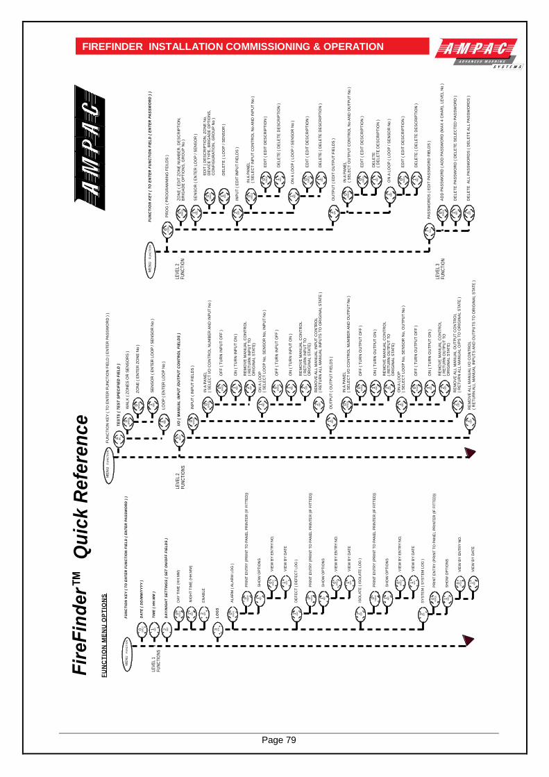
Page 79
FIREFINDER INSTALLATION COMMISSIONING & OPERATION
Fir
eF
ind
er™
Qu
ick
Re
fere
nc
e
FU
NC
TIO
N K
EY
( T
O E
NT
ER
FU
NC
TIO
N F
IEL
D (
EN
TE
R P
AS
SW
OR
D )
)
PR
OG
( P
RO
GR
AM
MIN
G F
EIL
DS
)
ED
IT (
ED
IT D
ES
CR
IPT
ION
)
DE
LE
TE
( L
OO
P /
SE
NS
OR
)
IN A
PA
NE
L
( S
EL
EC
T I
NP
UT
CO
NT
RO
L N
o A
ND
IN
PU
T N
o )
ED
IT (
ED
IT D
ES
CR
IPT
ION
)
ZO
NE
( E
DIT
ZO
NE
NU
MB
ER
, D
ES
CR
IPT
ION
, B
RIG
AD
E O
PT
ION
S,
GR
OU
P N
o )
INP
UT
( E
DIT
IN
PU
T F
IEL
DS
)
ED
IT (
DE
SC
RIP
TIO
N,
ZO
NE
No
, D
EV
ICE
TY
PE
, B
RIG
AD
E O
PT
ION
S,
CO
NF
IGU
RA
TIO
N,
GR
OU
P N
o )
DE
LE
TE
( D
EL
ET
E D
ES
CR
IPT
ION
)
ON
A L
OO
P (
LO
OP
/ S
EN
SO
R N
o )
SE
NS
OR
( E
NT
ER
LO
OP
/ S
EN
SO
R )
DE
LE
TE
( D
EL
ET
E D
ES
CR
IPT
ION
)
ED
IT (
ED
IT D
ES
CR
IPT
ION
)
IN A
PA
NE
L
( S
EL
EC
T O
UT
PU
T C
ON
TR
OL N
o A
ND
OU
TP
UT
No
)
ED
IT (
ED
IT D
ES
CR
IPT
ION
)
OU
TP
UT
( E
DIT
OU
TP
UT
FIE
LD
S )
DE
LE
TE
(
DE
LE
TE
DE
SC
RIP
TIO
N )
ON
A L
OO
P (
LO
OP
/ S
EN
SO
R N
o )
DE
LE
TE
( D
EL
ET
E D
ES
CR
IPT
ION
)
PA
SS
WO
RD
S (
ED
IT P
AS
SW
OR
D F
IEL
DS
)
AD
D P
AS
SW
OR
D (
AD
D P
AS
SW
OR
D (
MA
X 4
CH
AR
), L
EV
EL N
o )
DE
LE
TE
PA
SS
WO
RD
( D
EL
ET
E S
EL
EC
TE
D P
AS
SW
OR
D )
DE
LE
TE
A
LL P
AS
SW
OR
DS
( D
EL
ET
E A
LL P
AS
SW
OR
DS
)
LEV
EL
2F
UN
CT
ION
LEV
EL
3F
UN
CT
ION
FU
NC
TIO
N K
EY
( T
O E
NT
ER
FU
NC
TIO
N F
IEL
D (
EN
TE
R P
AS
SW
OR
D )
)
I/O
( M
AN
UA
L I
NP
UT
/O
UT
PU
T C
ON
TR
OL
FIE
LD
S )
OF
F (
TU
RN
IN
PU
T O
FF
)
ON
( T
UR
N I
NP
UT
ON
)
ON
A L
OO
P
( S
EL
EC
T L
OO
P N
o,
SE
NS
OR
No
, IN
PU
T N
o )
RE
MO
VE
AL
L M
AN
UA
L I
NP
UT
CO
NT
RO
L(
RE
TU
RN
AL
L M
AN
UA
L I
NP
UT
S T
O O
RIG
INA
L S
TA
TE
)
INP
UT
( I
NP
UT
FIE
LD
S )
IN A
PA
NE
L
( S
EL
EC
T I
/O C
ON
TR
OL N
UM
BE
R A
ND
IN
PU
T N
o )
RE
MO
VE
MA
NU
AL C
ON
TR
OL
( R
ET
UR
N I
NP
UT
TO
O
RIG
INA
L S
TA
TE
)
OF
F (
TU
RN
IN
PU
T O
FF
)
ON
( T
UR
N I
NP
UT
ON
)
RE
MO
VE
MA
NU
AL C
ON
TR
OL
( R
ET
UR
N I
NP
UT
TO
O
RIG
INA
L S
TA
TE
)
OF
F (
TU
RN
OU
TP
UT
OF
F )
ON
( T
UR
N O
UT
PU
T O
N )
ON
A L
OO
P
( S
EL
EC
T L
OO
P N
o,
SE
NS
OR
No
, O
UT
PU
T N
o )
RE
MO
VE
AL
L M
AN
UA
L O
UT
PU
T C
ON
TR
OL
( R
ET
UR
N A
LL M
AN
UA
L O
/PS
TO
OR
IGIN
AL S
TA
TE
)
OU
TP
UT
( O
UT
PU
T F
IEL
DS
)
IN A
PA
NE
L
( S
EL
EC
T I
/O C
ON
TR
OL N
UM
BE
R A
ND
OU
TP
UT
No
)
RE
MO
VE
MA
NU
AL C
ON
TR
OL
( R
ET
UR
N O
UT
PU
T T
O
OR
IGIN
AL S
TA
TE
)
OF
F (
TU
RN
OU
TP
UT
OF
F )
ON
( T
UR
N O
UT
PU
T O
N )
RE
MO
VE
MA
NU
AL C
ON
TR
OL
( R
ET
UR
N O
UT
PU
T T
O
OR
IGIN
AL S
TA
TE
)
RE
MO
VE
AL
L M
AN
UA
L I
/O C
ON
TR
OL
( R
ET
UR
N A
LL M
AN
UA
L I
NP
UT
S A
ND
OU
TP
UT
S T
O O
RIG
INA
L S
TA
TE
)
LEV
EL
2F
UN
CT
ION
S
FU
NC
TIO
N M
EN
U O
PT
ION
S
FU
NC
TIO
N K
EY
( T
O E
NT
ER
FU
NC
TIO
N F
IEL
D (
EN
TE
R P
AS
SW
OR
D )
)
DA
TE
( D
D/M
M/Y
YY
Y )
TIM
E (
HH
:MM
)
DA
Y/N
IGH
T S
ET
TIN
GS
( S
ET
ON
/OF
F F
IEL
DS
)
DA
Y T
IME
(H
H:M
M)
EN
AB
LE
LO
GS
LEV
EL
1F
UN
CT
ION
S
NIG
HT
TIM
E (
HH
:MM
)
AL
AR
M (
AL
AR
M L
OG
)
SH
OW
OP
TIO
NS
VIE
W B
Y E
NT
RY
NO
.
VIE
W B
Y D
AT
E
PR
INT
EN
TR
Y (
PR
INT
TO
PA
NE
L P
RIN
TE
R (
IF F
ITT
ED
))
DE
FE
CT
( D
EF
EC
T L
OG
)
SH
OW
OP
TIO
NS
VIE
W B
Y E
NT
RY
NO
.
VIE
W B
Y D
AT
E
PR
INT
EN
TR
Y (
PR
INT
TO
PA
NE
L P
RIN
TE
R (
IF F
ITT
ED
))
ISO
LA
TE
( I
SO
LA
TE
LO
G )
SH
OW
OP
TIO
NS
VIE
W B
Y E
NT
RY
NO
.
VIE
W B
Y D
AT
E
PR
INT
EN
TR
Y (
PR
INT
TO
PA
NE
L P
RIN
TE
R (
IF F
ITT
ED
))
WA
LK
( Z
ON
ES
OR
SE
NS
OR
S )
TE
ST
S (
TE
ST
SP
EC
IFIE
D F
IEL
D )
ZO
NE
( E
NT
ER
ZO
NE
No
)
SE
NS
OR
( E
NT
ER
LO
OP
/ S
EN
SO
R N
o )
LO
OP
( E
NT
ER
LO
OP
No
)P
QR
S6
SP
AC
E0 AB
C1
SP
AC
E0
SP
AC
E0
AB
C1
DE
F2
AB
C1
AB
C1
SP
AC
E0
AB
C1
SP
AC
E0
AB
C1
SP
AC
E0
GH
I3
AB
C1
SP
AC
E0
AB
C1
SP
AC
E0
TU
V7
SP
AC
E0 AB
C1 DE
F2
ME
NU
FU
NC
TIO
N
MN
O5
SP
AC
E0
SP
AC
E0 AB
C1 DE
F2
AB
C1
SP
AC
E0
SP
AC
E0
AB
C1 DE
F2
SP
AC
E0
SP
AC
E0 AB
C1 DE
F2
AB
C1
SP
AC
E0AB
C1 DE
F2
AB
C1
DE
F2 DE
F2
DE
F2
ME
NU
FU
NC
TIO
N
SP
AC
E0 DE
F2AB
C1
SP
AC
E0 AB
C1
GH
I3
ME
NU
FU
NC
TIO
N
2 DE
F
SP
AC
E0
SP
AC
E0 AB
C1
SP
AC
E0 AB
C1
SP
AC
E0 AB
C1
SP
AC
E0 AB
C1
DE
F2
SP
AC
E0 AB
C1
SP
AC
E0 AB
C1
1 AB
C
JKL4
SP
AC
E0
SP
AC
E0 AB
C1
AB
C1
SY
ST
EM
( S
YS
TE
M L
OG
)
SH
OW
OP
TIO
NS
VIE
W B
Y E
NT
RY
NO
.
VIE
W B
Y D
AT
E
PR
INT
EN
TR
Y (
PR
INT
TO
PA
NE
L P
RIN
TE
R (
IF F
ITT
ED
))
GH
I3
SP
AC
E0 AB
C1
SP
AC
E0 AB
C1

Page 80
FIREFINDER INSTALLATION COMMISSIONING & OPERATION
19 Battery and Power Supply Capacity Calculation
Battery Capacity
Step 1: Calculate the quiescent current of the entire system, quiescent meaning the system has no
alarms, faults or isolates and is in the normal state. Iq = Quiescent Current. Iq is best calculated by using a simple table as shown below.
List of Boards / Devices I Drawn mA Number Off Total I mA FACP 200 X 1 = 200 Detectors 0.25 X 30 = 7.5 Devices 10 X 1 = 10 Total = 217.5 Ancillary Loads X = Locks 100 X 4 = 400 Relays 20 X 2 = 40 Total = 440
Note: In some cases it is also advisable to actually measure the current draw to confirm the above
calculation. Step 2: Calculate the alarm current Ia, that is the current draw when the system is alarm plus Iq minus the current not being used by loads that do not consume power during an alarm. Ia = Alarm Current
List of Boards / Devices I Drawn mA Number Off Total I mA Sounder 40 X 4 = 160 Bells 80 X 5 = 400 Evac interface 20 X 1 = 20 Fire Control Stn. Interface 20 X 1 = 20 Warning signs 500 X 3 = 1500 Total = 2100
Step 3: Establish Ie that is the current draw Iq minus the loads that de-energise on alarm.
List of Boards / Devices I Drawn mA Number Off Total I mA Aircon relays 20 X 2 = 40 Electric locks 100 X 4 = 400 Total = 440
Total Alarm Load Ia ( mA ) = Iq – Ie + Ia in mA = 657.5 – 440 + 2100 = 2317.5 ( or 2.3175 Amps ) Required battery capacity at the end of its life. Note the X 1.25 to meet this requirement. = ( Iq X 24 ) + ( Ia X 0.5 ) X 1.25 = ( 0.658 X 24 ) + ( 2.32 X 0.5 ) X 1.25 = ( 15.8 + 1.16 ) X 1.25 = 21.2Ah Rounded UP to the nearest battery available = 25Ah.

Page 81
FIREFINDER INSTALLATION COMMISSIONING & OPERATION
Battery Charger Calculation Battery Charger Requirements = battery charged for 24 hours Battery Charging Current Required = 25 24 X e Where e is the efficiency say 0.8 in this example
= 1.3A
Power Supply Requirement Select the greater of:
( i ) Ia + non-battery backed ancillary loads
List of Boards / Devices I Drawn mA Number Off Total I A Door Holders 50 X 4 = 0.2
= 2.32 + 0.2 = 2.52A
OR
( ii ) Iq + non battery backed quiescent loads
List of Boards / Devices I Drawn mA Number Off Total I A Door Holders 50 X 6 = 0.3
= 0.658 + 0.3 = 0.958A In this case the required power supply rating is 2.52A Where the power supply is also used as the charger, the battery charger requirement MUST be added to the minimum power supply requirement to obtain the minimum power supply requirement. In this case the requirement would be;
= Ia + battery charger requirement = 2.52 + 1.3 =3.82A

UNCONTROLLED DOCUMENT
NOTE: Due to Ampac’s commitment to continuous improvement specifications may change without notice.
Recommended