Fire Detection &Evacuation System
www.shieldglobal.com


SHIELD
3
www.shieldglobal.com
In line with SHIELD policy for continuous product development, SHIELD has the right to change specifications without prior notice.Images shown in this catalogue are for illustrations purposes only.
Competence and innovation driven by consistent market development and customer requirements have shaped the successful development of the SHIELD Brand. The extensive product range of the market leader in the field of fire detection technology contains single, individu-ally integrable system performances. In this way, a cus-tomized overall fire protection concept can be planned and realized for every need with optimally synchronized products.
Performance is in international demand, SHIELD is among the highly accredited fire alarm companies that meet rigorous British and American standards for all projects from small conventional system to multi site networks.
Certifications such as UL and FM approvals have earned SHIELD a world-renowned reputation with quality prod-ucts and powerful solutions.
A strong brand is generally known to be a secure basis for close and lasting customer relationships. In accord-ance with this, SHIELD uses available potential in order to keep on growing in a dynamic competitive environment. And at the same time, SHIELD stands for innovative and high quality fire alarm and evacuation systems.
We invite you to explore and visit our new website www.shieldglobal.com. You can also send us your feedback and inquiry through our user-friendly online forms.
Introduction
The SHIELD range of Address-able Fire Detectors is advanced in design and performance and offers unique features that ben-efit both the installer and the end user.
SHIELD Fire Detectors uses a ‘central intelligence’ system where all the decisions are made by the control panel. Each detector is addressed using SHIELD’s patented XPERT Card and supplied with the mounting bases. The SHIELD product line includes a photo-electric detector, a heat detector, a multisensor, an isolator and a series of modules.
KEY FEATURES:
• XPERT Card addressing
• Analog value report
• Alarm flags for fast alarm response
• Synchronization of all loop powered notification devices
• Advanced error check
ADDRESSABLEFIRE DETECTORS
SHIELD
5
www.shieldglobal.com
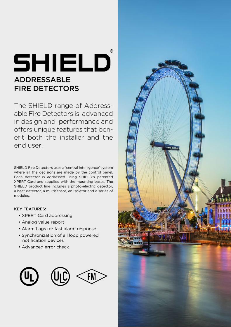
SHIELD Photo-Electric Smoke Detector S-A4011
SHIELD Photo-Electric Smoke Detector
works on the light-scatter principle and is
ideal for applications where slow-burning
or smoldering fires are likely.
• Responds well to slow-burning, smoldering fires• Well suited for bedrooms and escape routes• Unaffected by atmospheric pressure
.......................................................................................................................................................................................................................................................................................................
.......................................................................................................................................................................................................................................................................................................
SHIELD Heat Detector S-A4013
SHIELD Heat Detector is distinguish-able by the low airflow resistant case and uses a single thermistor to sense the air temperature around the detec-tor.
• Ideal for environments that are dirty or smoky under normal conditions• Well suited for warehouses, loading docks and parking garages• Unaffected by wind or atmospheric pressure• Remote test feature
Analog Addressable Fire Detectors UL / ULC/ FM
SHIELD Multisensor S-A4014
SHIELD Multisensor contains a photo-electric smoke sensor and a thermis-tor (temperature sensor) whose out-puts are combined to give the final analog value.
• Sensitive to a wide range of fires• Well suited for environments such as hotel bedrooms, warehouses & loading docks• Unaffected by wind or atmospheric pressure
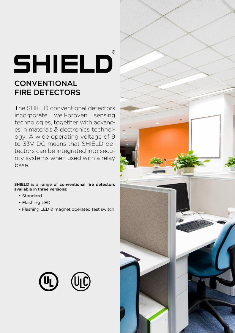
The SHIELD conventional detectors incorporate well-proven sensing technologies, together with advanc-es in materials & electronics technol-ogy. A wide operating voltage of 9 to 33V DC means that SHIELD de-tectors can be integrated into secu-rity systems when used with a relay base.
SHIELD is a range of conventional fire detectors available in three versions:
• Standard
• Flashing LED
• Flashing LED & magnet operated test switch
CONVENTIONALFIRE DETECTORS
SHIELD
7
www.shieldglobal.com
Conventional Fire Detectors UL / ULC
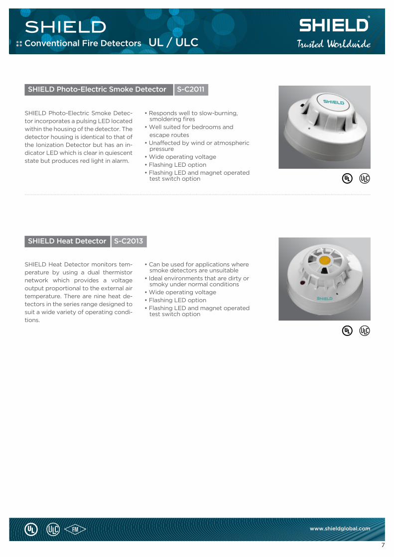
SHIELD Photo-Electric Smoke Detector S-C2011
SHIELD Photo-Electric Smoke Detec-tor incorporates a pulsing LED located within the housing of the detector. The detector housing is identical to that of the Ionization Detector but has an in-dicator LED which is clear in quiescent state but produces red light in alarm.
• Responds well to slow-burning, smoldering fires• Well suited for bedrooms and escape routes• Unaffected by wind or atmospheric pressure• Wide operating voltage• Flashing LED option• Flashing LED and magnet operated test switch option
.......................................................................................................................................................................................................................................................................................................
SHIELD Heat Detector S-C2013
SHIELD Heat Detector monitors tem-perature by using a dual thermistor network which provides a voltage output proportional to the external air temperature. There are nine heat de-tectors in the series range designed to suit a wide variety of operating condi-tions.
• Can be used for applications where smoke detectors are unsuitable• Ideal environments that are dirty or smoky under normal conditions• Wide operating voltage• Flashing LED option• Flashing LED and magnet operated test switch option
BASES
SHIELD
9
www.shieldglobal.com
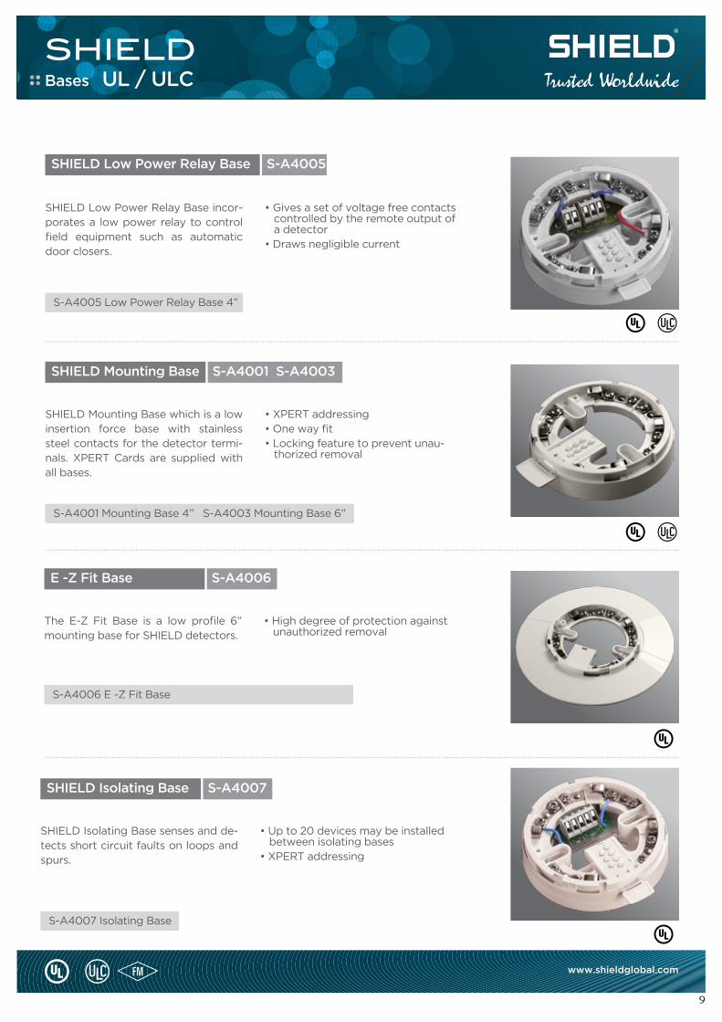
SHIELD Low Power Relay Base S-A4005
SHIELD Low Power Relay Base incor-porates a low power relay to control field equipment such as automatic door closers.
• Gives a set of voltage free contacts controlled by the remote output of a detector• Draws negligible current
.......................................................................................................................................................................................................................................................................................................
SHIELD Mounting Base
SHIELD Isolating Base
S-A4001 S-A4003
S-A4007
SHIELD Mounting Base which is a low insertion force base with stainless steel contacts for the detector termi-nals. XPERT Cards are supplied with all bases.
SHIELD Isolating Base senses and de-tects short circuit faults on loops and spurs.
• XPERT addressing• One way fit• Locking feature to prevent unau- thorized removal
• Up to 20 devices may be installed between isolating bases• XPERT addressing
.......................................................................................................................................................................................................................................................................................................
.......................................................................................................................................................................................................................................................................................................
Bases UL / ULC
S-A4005 Low Power Relay Base 4”
S-A4001 Mounting Base 4” S-A4003 Mounting Base 6”
S-A4007 Isolating Base
E -Z Fit Base S-A4006
The E-Z Fit Base is a low profile 6” mounting base for SHIELD detectors.
• High degree of protection against unauthorized removal
S-A4006 E -Z Fit Base
MODULES
SHIELD
11
www.shieldglobal.com
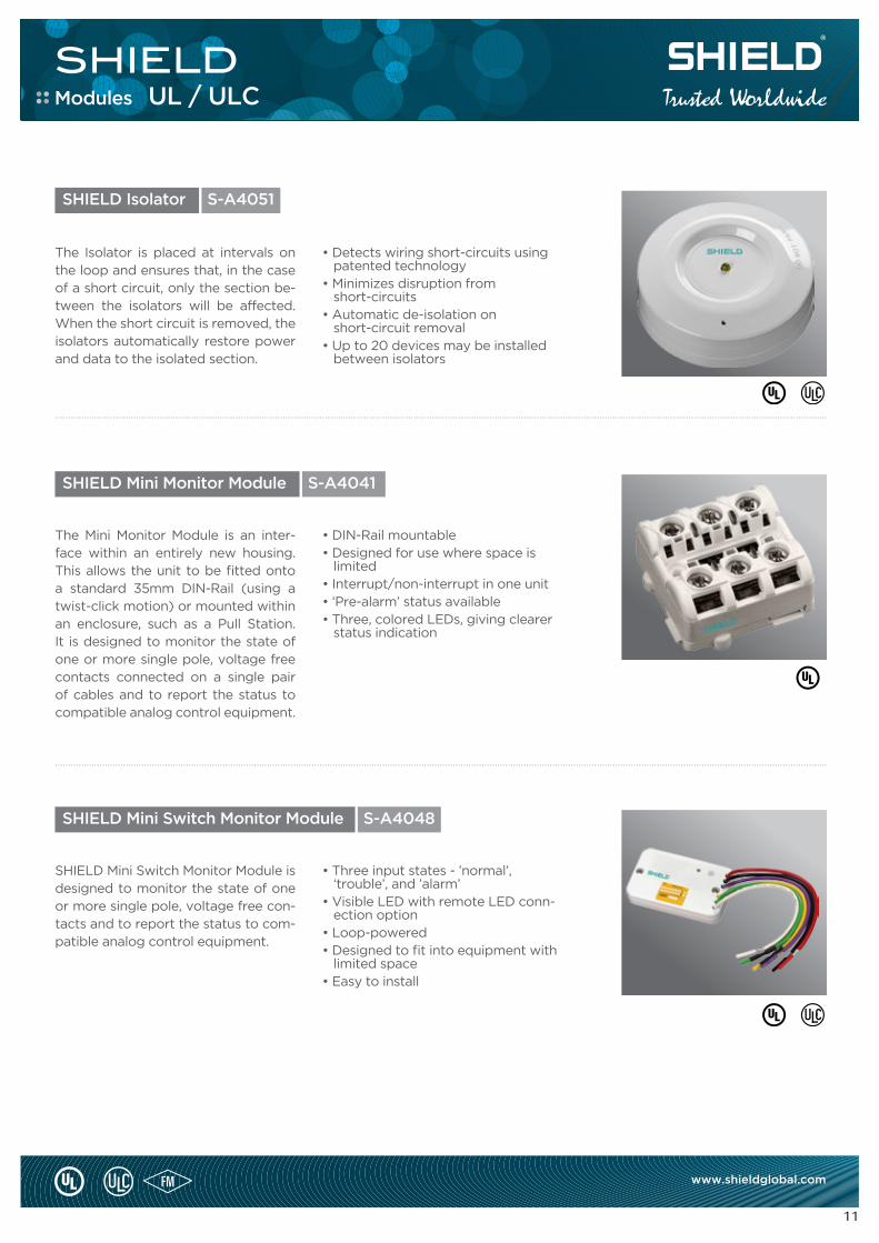
SHIELD Isolator S-A4051
The Isolator is placed at intervals on the loop and ensures that, in the case of a short circuit, only the section be-tween the isolators will be affected. When the short circuit is removed, the isolators automatically restore power and data to the isolated section.
• Detects wiring short-circuits using patented technology• Minimizes disruption from short-circuits• Automatic de-isolation on short-circuit removal• Up to 20 devices may be installed between isolators
.......................................................................................................................................................................................................................................................................................................
SHIELD Mini Monitor Module
SHIELD Mini Switch Monitor Module
S-A4041
S-A4048
The Mini Monitor Module is an inter-face within an entirely new housing. This allows the unit to be fitted onto a standard 35mm DIN-Rail (using a twist-click motion) or mounted within an enclosure, such as a Pull Station. It is designed to monitor the state of one or more single pole, voltage free contacts connected on a single pair of cables and to report the status to compatible analog control equipment.
SHIELD Mini Switch Monitor Module is designed to monitor the state of one or more single pole, voltage free con-tacts and to report the status to com-patible analog control equipment.
• DIN-Rail mountable• Designed for use where space is limited• Interrupt/non-interrupt in one unit• ‘Pre-alarm’ status available• Three, colored LEDs, giving clearer status indication
• Three input states - ’normal’, ‘trouble’, and ’alarm’• Visible LED with remote LED conn- ection option• Loop-powered• Designed to fit into equipment with limited space• Easy to install
.......................................................................................................................................................................................................................................................................................................
Modules UL / ULC
SHIELD
12
www.shieldglobal.com
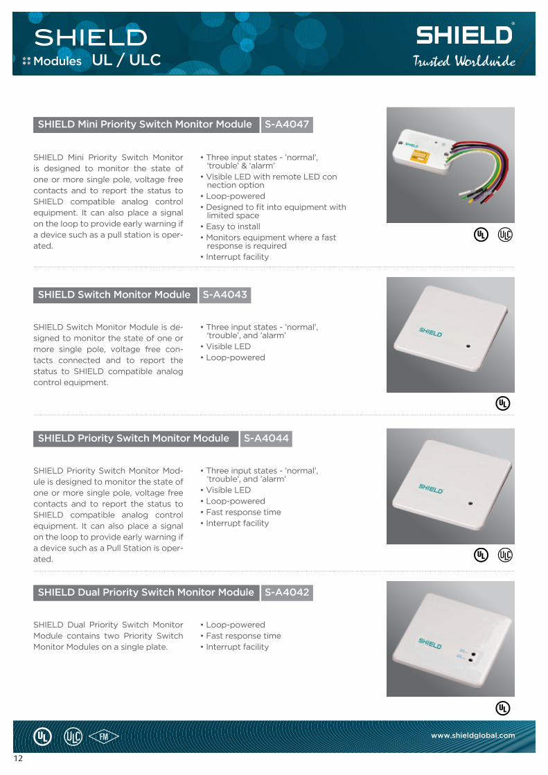
SHIELD Mini Priority Switch Monitor is designed to monitor the state of one or more single pole, voltage free contacts and to report the status to SHIELD compatible analog control equipment. It can also place a signal on the loop to provide early warning if a device such as a pull station is oper-ated.
• Three input states - ’normal’, ‘trouble’ & ‘alarm’• Visible LED with remote LED con nection option• Loop-powered• Designed to fit into equipment with limited space• Easy to install• Monitors equipment where a fast response is required• Interrupt facility
.......................................................................................................................................................................................................................................................................................................
.......................................................................................................................................................................................................................................................................................................
.......................................................................................................................................................................................................................................................................................................
SHIELD Switch Monitor Module
SHIELD Priority Switch Monitor Module
SHIELD Dual Priority Switch Monitor Module
SHIELD Mini Priority Switch Monitor Module
S-A4043
S-A4044
S-A4042
S-A4047
SHIELD Switch Monitor Module is de-signed to monitor the state of one or more single pole, voltage free con-tacts connected and to report the status to SHIELD compatible analog control equipment.
SHIELD Priority Switch Monitor Mod-ule is designed to monitor the state of one or more single pole, voltage free contacts and to report the status to SHIELD compatible analog control equipment. It can also place a signal on the loop to provide early warning if a device such as a Pull Station is oper-ated.
SHIELD Dual Priority Switch Monitor Module contains two Priority Switch Monitor Modules on a single plate.
• Three input states - ’normal’, ‘trouble’, and ’alarm’• Visible LED• Loop-powered
• Three input states - ’normal’, ‘trouble’, and ’alarm’• Visible LED• Loop-powered• Fast response time• Interrupt facility
• Loop-powered• Fast response time• Interrupt facility
Modules UL / ULC
SHIELD
13
www.shieldglobal.com
.......................................................................................................................................................................................................................................................................................................
.......................................................................................................................................................................................................................................................................................................
.......................................................................................................................................................................................................................................................................................................
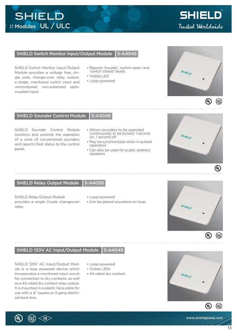
SHIELD Switch Monitor Input/Output Module
SHIELD Sounder Control Module
SHIELD Relay Output Module
SHIELD 120V AC Input/Output Module
S-A4045
S-A4046
S-A4050
S-A4049
SHIELD Switch Monitor Input/Output Module provides a voltage free, sin-gle pole, change-over relay output, a single, monitored switch input and unmonitored, non-polarized opto-coupled input.
SHIELD Sounder Control Module monitors and controls the operation of a zone of conventional sounders and reports their status to the control panel.
SHIELD Relay Output Module provides a single 2-pole changeover relay.
SHIELD 120V AC Input/Output Mod-ule is a loop powered device which incorporates a monitored input circuit for connection to dry contacts, as well as a 4A rated dry contact relay output. It is mounted in a plastic facia plate for use with a 4” square or 2 gang electri-cal back box.
• Reports ‘trouble’, ‘switch open’ and ‘switch closed’ levels• Visible LED• Loop-powered
• Allows sounders to be operated continuously or be pulsed, 1 second on, 1 second off• May be synchronized when in pulsed operation• Can also be used for public address speakers
• Loop-powered• Can be placed anywhere on loop
• Loop-powered• Visible LEDs• 4A rated dry contact
Modules UL / ULC
NOTIFICATION DEVICES
SHIELD
15
www.shieldglobal.com
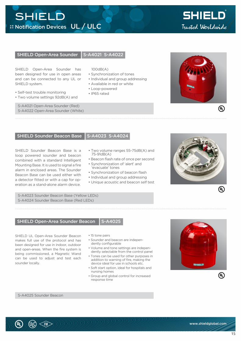
SHIELD Open-Area Sounder
SHIELD Sounder Beacon Base
SHIELD Open-Area Sounder Beacon
S-A4021 S-A4022
S-A4023 S-A4024
S-A4025
SHIELD Open-Area Sounder has been designed for use in open areas and can be connected to any UL or SHIELD system.
• Self-test trouble monitoring• Two volume settings 92dB(A) and
SHIELD Sounder Beacon Base is a loop powered sounder and beacon combined with a standard Intelligent Mounting Base. It is used to signal a fire alarm in enclosed areas. The Sounder Beacon Base can be used either with a detector fitted or with a cap for op-eration as a stand-alone alarm device.
SHIELD UL Open-Area Sounder Beacon makes full use of the protocol and has been designed for use in indoor, outdoor and open-areas. When the fire system is being commissioned, a Magnetic Wand can be used to adjust and test each
sounder locally.
100dB(A)• Synchronization of tones• Individual and group addressing• Available in red or white• Loop-powered• IP65 rated
• Two volume ranges 55-75dB(A) and 75-91dB(A)• Beacon flash rate of once per second• Synchronization of ‘alert’ and ‘evacuate’ tones• Synchronization of beacon flash• Individual and group addressing• Unique acoustic and beacon self test
• 15 tone pairs
• Sounder and beacon are indepen- dently configurable
• Volume and tone settings are indepen- dently selectable from the control panel
• Tones can be used for other purposes in addition to warning of fire, making the device ideal for use in schools etc.
• Soft start option, ideal for hospitals and nursing homes
• Group and global control for increased response time
.......................................................................................................................................................................................................................................................................................................
.......................................................................................................................................................................................................................................................................................................
S-A4021 Open-Area Sounder (Red)S-A4022 Open-Area Sounder (White)
S-A4023 Sounder Beacon Base (Yellow LEDs)S-A4024 Sounder Beacon Base (Red LEDs)
S-A4025 Sounder Beacon
Notification Devices UL / ULC
PULL STATIONS
SHIELD
17
www.shieldglobal.com
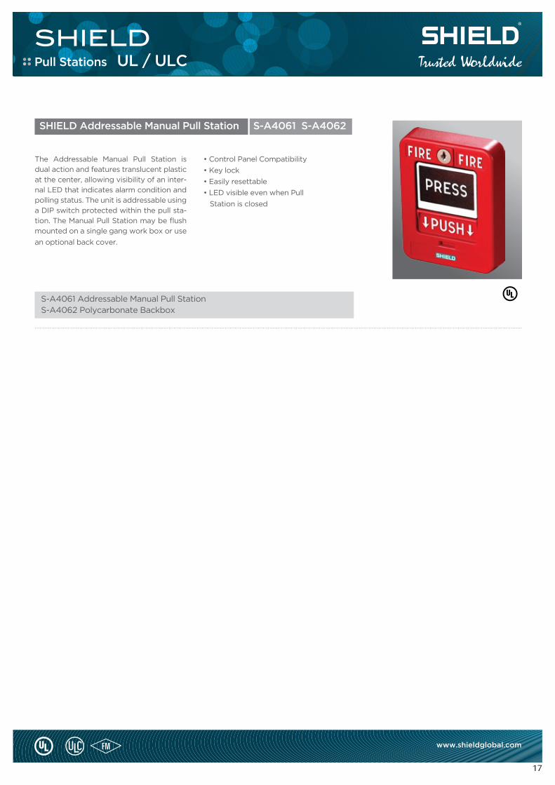
SHIELD Addressable Manual Pull Station S-A4061 S-A4062
The Addressable Manual Pull Station is
dual action and features translucent plastic
at the center, allowing visibility of an inter-
nal LED that indicates alarm condition and
polling status. The unit is addressable using
a DIP switch protected within the pull sta-
tion. The Manual Pull Station may be flush
mounted on a single gang work box or use
an optional back cover.
• Control Panel Compatibility
• Key lock
• Easily resettable
• LED visible even when Pull
Station is closed
.......................................................................................................................................................................................................................................................................................................
S-A4061 Addressable Manual Pull StationS-A4062 Polycarbonate Backbox
Pull Stations UL / ULC
FIRE ALARM CONTROL PANELS
SHIELD
19
www.shieldglobal.com
SHIELD OMEGA with Network Interface Card
Network uses standard Cat 5 cabling
Up to 2,000 ft. between adjacent panels
115 Kbps constant network speed
TCP and UPD communications through Omega-N
Total network delay less than 3 sec. with 127 panels
Network jacks – RJ-45 (Omega-N and Ethernet)
Mapped Network; Display messages for Any or All nodes
SHIELD OMEGA with Media Gateway®
All the features of the Ether/DACT and NIC plus:
Enables network programming with direct TCP/IP access to each panel
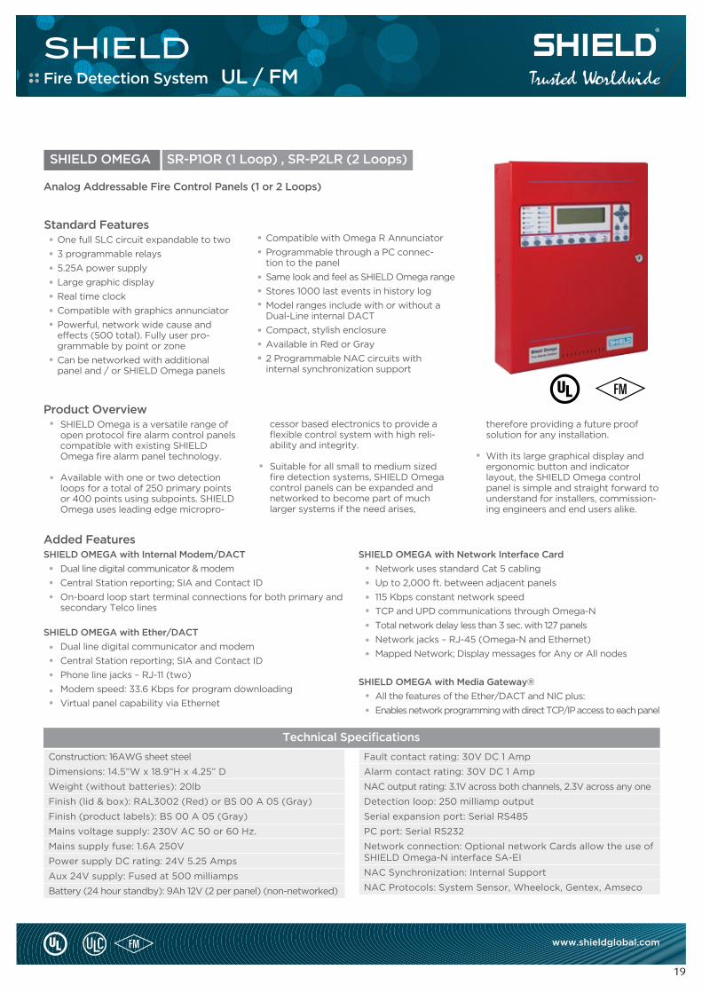
SHIELD OMEGA SR-P1OR (1 Loop) , SR-P2LR (2 Loops)
Standard FeaturesOne full SLC circuit expandable to two
3 programmable relays
5.25A power supply
Large graphic display
Real time clock
Compatible with graphics annunciator
Powerful, network wide cause and effects (500 total). Fully user pro- grammable by point or zone
Can be networked with additional panel and / or SHIELD Omega panels
Compatible with Omega R Annunciator
Programmable through a PC connec- tion to the panel
Same look and feel as SHIELD Omega range
Stores 1000 last events in history log
Model ranges include with or without a Dual-Line internal DACT
Compact, stylish enclosure
Available in Red or Gray
2 Programmable NAC circuits with internal synchronization support
Added FeaturesSHIELD OMEGA with Internal Modem/DACT
Dual line digital communicator & modem
Central Station reporting; SIA and Contact ID
On-board loop start terminal connections for both primary and secondary Telco lines
SHIELD OMEGA with Ether/DACT
Dual line digital communicator and modem
Central Station reporting; SIA and Contact ID
Phone line jacks – RJ-11 (two)
Modem speed: 33.6 Kbps for program downloading
Virtual panel capability via Ethernet
Analog Addressable Fire Control Panels (1 or 2 Loops)
Product OverviewSHIELD Omega is a versatile range of open protocol fire alarm control panels compatible with existing SHIELD Omega fire alarm panel technology.
Available with one or two detection loops for a total of 250 primary points or 400 points using subpoints. SHIELD Omega uses leading edge micropro-
cessor based electronics to provide a flexible control system with high reli-ability and integrity.
Suitable for all small to medium sized fire detection systems, SHIELD Omega control panels can be expanded and networked to become part of much larger systems if the need arises,
Construction: 16AWG sheet steel
Dimensions: 14.5”W x 18.9”H x 4.25” D
Weight (without batteries): 20lb
Finish (lid & box): RAL3002 (Red) or BS 00 A 05 (Gray)
Finish (product labels): BS 00 A 05 (Gray)
Mains voltage supply: 230V AC 50 or 60 Hz.
Mains supply fuse: 1.6A 250V
Power supply DC rating: 24V 5.25 Amps
Aux 24V supply: Fused at 500 milliamps
Battery (24 hour standby): 9Ah 12V (2 per panel) (non-networked)
Fault contact rating: 30V DC 1 Amp
Alarm contact rating: 30V DC 1 Amp
NAC output rating: 3.1V across both channels, 2.3V across any one
Detection loop: 250 milliamp output
Serial expansion port: Serial RS485
PC port: Serial RS232
Network connection: Optional network Cards allow the use of SHIELD Omega-N interface SA-EI
NAC Synchronization: Internal Support
NAC Protocols: System Sensor, Wheelock, Gentex, Amseco
therefore providing a future proof solution for any installation.
With its large graphical display and ergonomic button and indicator layout, the SHIELD Omega control panel is simple and straight forward to understand for installers, commission-ing engineers and end users alike.
Technical Specifications
Fire Detection System UL / FM
SHIELD
20
www.shieldglobal.com
Added FeaturesSHIELD Omega-X with eNET
Network uses standard RS485 cablingUp to 2,000 ft. between adjacent panels115 Kbps constant network speedSecure, fault tolerant communication
Up to 64 nodes
SHIELD Omega-X with DACTDual line digital communicator & modemContact ID and SIA reportingUL 864 9th edition listedZone or point reportingBackup and duplicate reporting
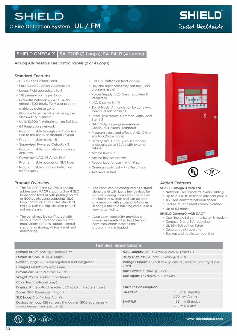
The Panel can be configured as a stand alone panel with just a few devices for a small building, it can also operate as the building system and can be part of a network with a total of 64 nodes serving a multiple building campus or a very large facility.
Auto Learn capability provides a convenient method to troubleshoot new installations before final programming is loaded.
Product OverviewThe SA-P20R and SA-P4LR analogaddressable FACP supports 2 or 4 SLCloops for a total of 500 primary points or 800 points using subpoints. SLC loop communications uses standardtwisted pair cabling, shielded cable is not necessary.
The panel may be configured with various communication cards; Com-munications options support central station monitoring, Virtual Panel, and networking.
Fire Drill button on front display
Day and night sensitivity settings (user programmable)
Power Supply: 5.25 Amp, regulated & integrated
LCD Display: 8x40
Zonal Mode: Annunciation by zone w/o individual relationships
Panel Ring Modes: Common, Zonal, and Stage 2
NAC Outputs programmable asContinuous, March, Temporal
Program cause and effects AND, OR, or any two (Cross Zone)
Battery size: Up to 17 Ah in standard enclosure; up to 52 Ah with external cabinet
Access levels: 3
Access key switch: Yes
Recognized for use in High Rise
One-man walk test – Fire Test Mode
Available in Red
SHIELD OMEGA X SA-P20R (2 Loops), SA-P4LR (4 Loops)
Standard FeaturesUL 864 9th Edition listed
Multi-Loop 2 Analog Addressable
Loops Field upgradable to 4
126 primary points per loop
Powerful, network wide cause and effects (500 total). Fully user program-
mable by point or zone
800 points per panel when using de-vices with sub-points
Up to 10,000 ft. wiring length on SLC loop
64 Panels on a network
Programmable through a PC connec-tion to the panel, or through keypad
Programmable relays – 5
Supervised Powered Outputs – 3
Programmable notification appliance circuits:4
Power per NAC: 1.6 Amps Max
Programmable outputs on SLC loop
Programmable Function button on front display
Analog Addressable Fire Control Panels (2 or 4 Loops)
Primary AC: 230VAC @ 2 Amps 60hz
Output DC: 24VDC @ 4 Amps
Power Supply: 5.25 Amp regulated and integrated
Charger Current: 1.25 Amps max.
Dimensions: 14.5”W x 24”H x 5”D
Weight: 25 lbs. (without batteries)
Color: Red (optional gray)
Display: 8 line x 40 character LCD (320 characters total)
Zones: 500 Zones per network
SLC loops: 2 or 4 (class A or B)
Devices per loop: 126 sensors & modules (800 addresses + subaddresses max. per panel)
NAC Outputs: (4) 1.6 Amp @ 24VDC (class B)
Relay Outputs: (5) Form C 1 Amp @ 30VDC
Voltage Outputs: (3) 500mA @ 24VDC, reverse polarity super-vised
Aux. Power: 500mA @ 24VDC
Aux. Inputs: (3) digital pull downs
Current Consumption
SA-P2OR 355 mA Standby
650 mA Alarm
SA-P4LR 455 mA Standby
765 mA Alarm
Technical Specifications
Fire Detection System UL / FM
SHIELD
21
www.shieldglobal.com
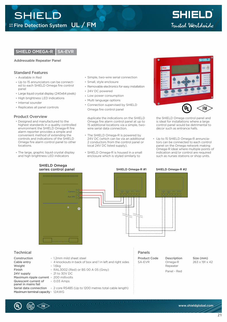
the SHIELD Omega control panel and is ideal for installations where a large control panel would be detrimental to décor such as entrance halls.
Up to 15 SHIELD Omega-R annuncia-tors can be connected to each control panel on the Omega network making Omega-R ideal where multiple points of indication and/or control are required such as nurses stations or shop units.
duplicate the indications on the SHIELD Omega fire alarm control panel at up to 15 additional locations via a simple, two-wire serial data connection.
The SHIELD Omega-R is powered by 24V DC (which can be via an additional 2 conductors from the control panel or local 24V DC listed supply).
SHIELD Omega-R is housed in a small enclosure which is styled similarly to
Product OverviewDesigned and manufactured to the highest standards in a quality controlled environment the SHIELD Omega-R fire alarm reporter provides a simple and convenient method of extending the controls and indications of the SHIELD Omega fire alarm control panel to other locations.
The large, graphic liquid crystal display and high brightness LED indicators
PanelsTechnical
SHIELD OMEGA-R SA-EVR
Standard FeaturesAvailable in Red
Up to 15 annunciators can be connect-ed to each SHIELD Omega fire control panel
Large liquid crystal display (240x64 pixels)
High brightness LED indications
Internal sounder
Replicates all panel controls
Addressable Repeater Panel
Simple, two-wire serial connection
Small, style enclosure
Removable electronics for easy installation
24V DC powered
Low power consumption
Multi language options
Connection supervised by SHIELD
Omega fire control panel
Product Code Description Size (mm)SA-EVR Omega-R 263 x 191 x 42 Repeater
Panel - Red
ConstructionCable entryWeightFinish24V supplyMaximum ripple currentQuiescent current of panel in mains failSerial data connectionMaximum terminal capacity
- 1.2mm mild sheet steel- 4 knockouts in back of box and 1 in left and right sides- 1.6kg- RAL3002 (Red) or BS 00 A 05 (Grey)- 21 to 30V DC- 200 millivolts- 0.03 Amps
- 2 core RS485 (Up to 1200 metres total cable length)- 12AWG
SHIELD Omegaseries control panel SHIELD Omega-R #1
CommsIn
CommsOut
24V In 24V Ou t
SHIELD Omega-R #2
CommsIn
CommsOut
24V In 24V Ou tComm s
Aux 24V
.....................................................................
Fire Detection System UL / FM
SHIELD
22
www.shieldglobal.com
Support for 100’s of graphics
Display and control for multiple panels
Event history explore and export facility to text or HTML documents
A comprehensive history logging and reporting system allows analysis of events and trends to be identified to reduce unwanted alarms.
Easy to programme and simple to use, Locator provides a cost effective solu-tion for fire alarm management at many levels.
The system is highly configurable in terms of the style of presentation so that the end user can be presented with maps, text, photographs, audio or a combination of all as required.
User profiles allow the system manager to control the facilities available to each individual system user.
Product Overview
SHIELD fire control panels can send data to, and be controlled by, the LO-CATOR system providing a single point of co-ordination for all alarms.
The powerful 32 bit programme features a standard Windows look and feel and runs under Windows® 2000 , XP, Vista or Windows 7 Professional.
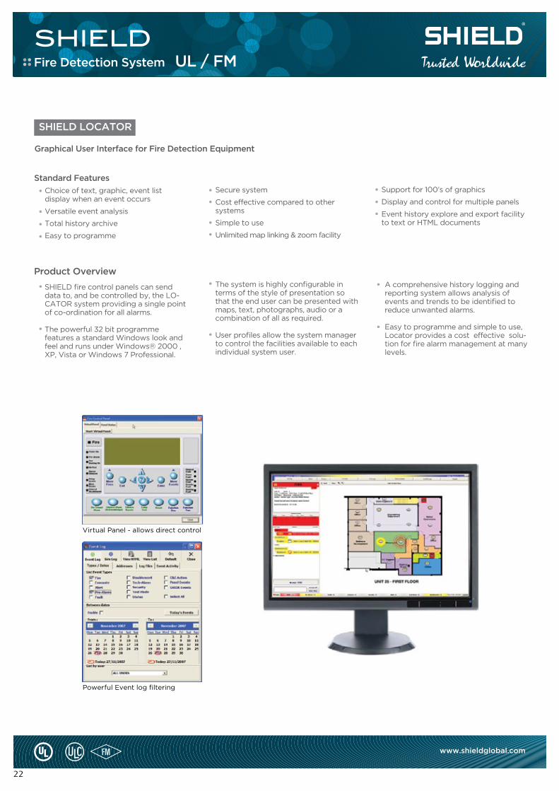
SHIELD LOCATOR
Standard Features
Choice of text, graphic, event list display when an event occurs
Versatile event analysis
Total history archive
Easy to programme
Graphical User Interface for Fire Detection Equipment
Secure system
Cost effective compared to other systems
Simple to use
Unlimited map linking & zoom facility
Powerful Event log filtering
Virtual Panel - allows direct control
Fire Detection System UL / FM
SHIELD
23
www.shieldglobal.com
Technical
Processor
Operating system
Memory
Hard disk
Graphics
Sound card
Loudspeaker
Monitor
Pointing device
Printer
Parallel port
Serial ports
CDROM drive
Backup drive
Intel Pentium 1Ghz
Windows® XP/Vista , 7 Professional
1Gb minimum
10GB minimum
1024 x 768 16M colours
Any PC sound card
Any PC speakers
Any that supports above graphics driver
Mouse essential
Optional
Optional
One RS232 per network
Any
CD Writer
RangeProduct Code Description
Recommended Minimum Notes
S1001S1004S1008S1016S1032S1064
Locator software - Single panel package
Locator software - 4 panel package
Locator software - 8 panel package
Locator software - 16 panel package
Locator software - 32 panel package
Locator software - 64 panel package
Note: Locator for use with SHIELD Panels. SHIELD Omega 6 & 8 loop panels are considered 2 panels in the packages above.
The faster the better
Will operate under Windows® 2000
The larger the better.The driver must allow this mode with large fonts. Separate Graphics card with 256MB graphics memory recommended
More convenient if built into PC.
17 inch minimum recommended, the larger the better. (1024 x 768)
Third button and wheels are supported. Touch screen option supported
Any type.
Required if parallel printer to be used.
Isolated converter supplied for connection to fire
alarm system.
Required for installation of software and updates.
To back up history.
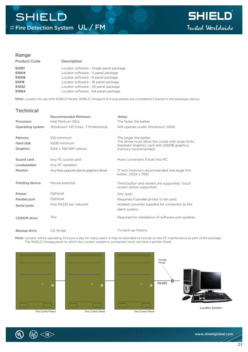
Fire Control Panel Fire Control Panel Fire Control Panel
DongleFitted
Locator System
RS485
Note: Locator will be operating 24 hours a day for many years. It may be desirable to include on site PC maintenance as part of the package. The SHIELD Omega panel to which the Locator system is connected must not have a printer fitted.
Fire Detection System UL / FM
VOICE EVACUATIONSYSTEMS
SHIELD
25
www.shieldglobal.com
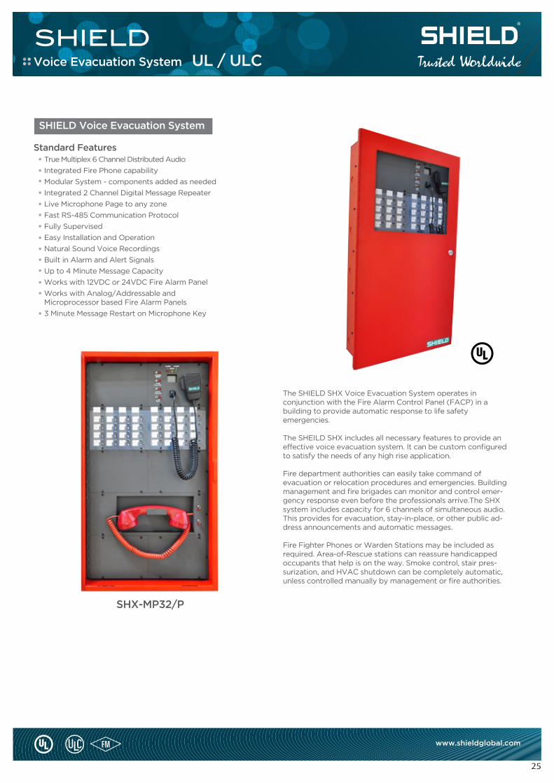
The SHIELD SHX Voice Evacuation System operates inconjunction with the Fire Alarm Control Panel (FACP) in a building to provide automatic response to life safetyemergencies.
The SHEILD SHX includes all necessary features to provide an effective voice evacuation system. It can be custom configured to satisfy the needs of any high rise application.
Fire department authorities can easily take command of evacuation or relocation procedures and emergencies. Building management and fire brigades can monitor and control emer-gency response even before the professionals arrive.The SHX system includes capacity for 6 channels of simultaneous audio. This provides for evacuation, stay-in-place, or other public ad-dress announcements and automatic messages.
Fire Fighter Phones or Warden Stations may be included as required. Area-of-Rescue stations can reassure handicapped occupants that help is on the way. Smoke control, stair pres-surization, and HVAC shutdown can be completely automatic, unless controlled manually by management or fire authorities.
SHX-MP32/P
SHIELD Voice Evacuation System
Standard FeaturesTrue Multiplex 6 Channel Distributed Audio
Integrated Fire Phone capability
Modular System - components added as needed
Integrated 2 Channel Digital Message Repeater
Live Microphone Page to any zone
Fast RS-485 Communication Protocol
Fully Supervised
Easy Installation and Operation
Natural Sound Voice Recordings
Built in Alarm and Alert Signals
Up to 4 Minute Message Capacity
Works with 12VDC or 24VDC Fire Alarm Panel
Works with Analog/Addressable andMicroprocessor based Fire Alarm Panels
3 Minute Message Restart on Microphone Key
Voice Evacuation System UL / ULC
SHIELD
26
www.shieldglobal.com
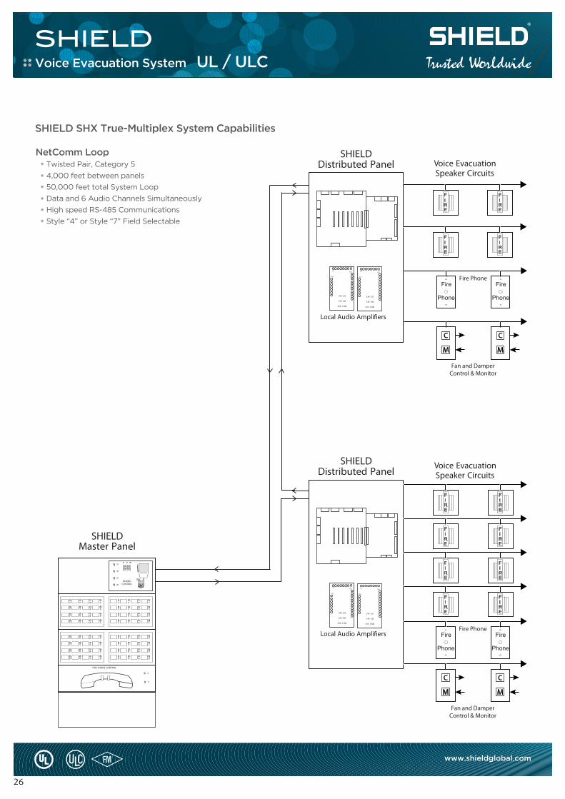
SHIELD SHX True-Multiplex System Capabilities
NetComm LoopTwisted Pair, Category 5
4,000 feet between panels
50,000 feet total System Loop
Data and 6 Audio Channels Simultaneously
High speed RS-485 Communications
Style “4” or Style “7” Field Selectable
Voice Evacuation System UL / ULC
SHIELD
27
www.shieldglobal.com
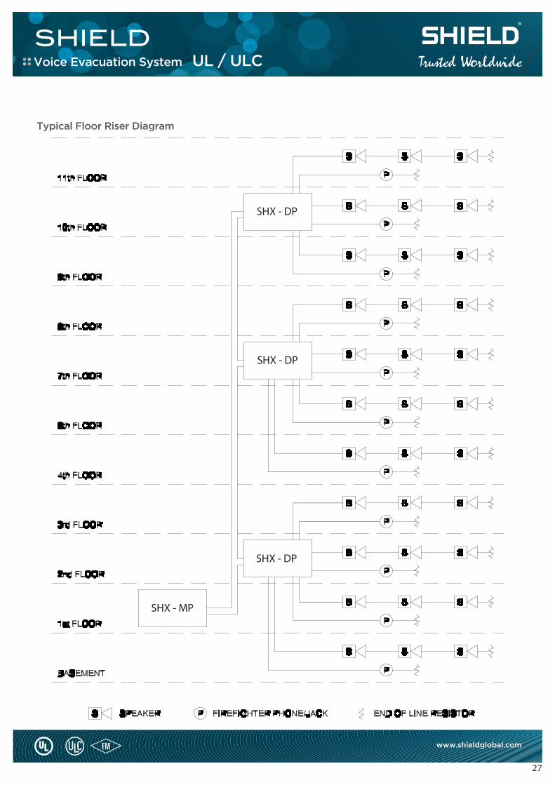
Typical Floor Riser Diagram
Voice Evacuation System UL / ULC
SHIELD
28
www.shieldglobal.com
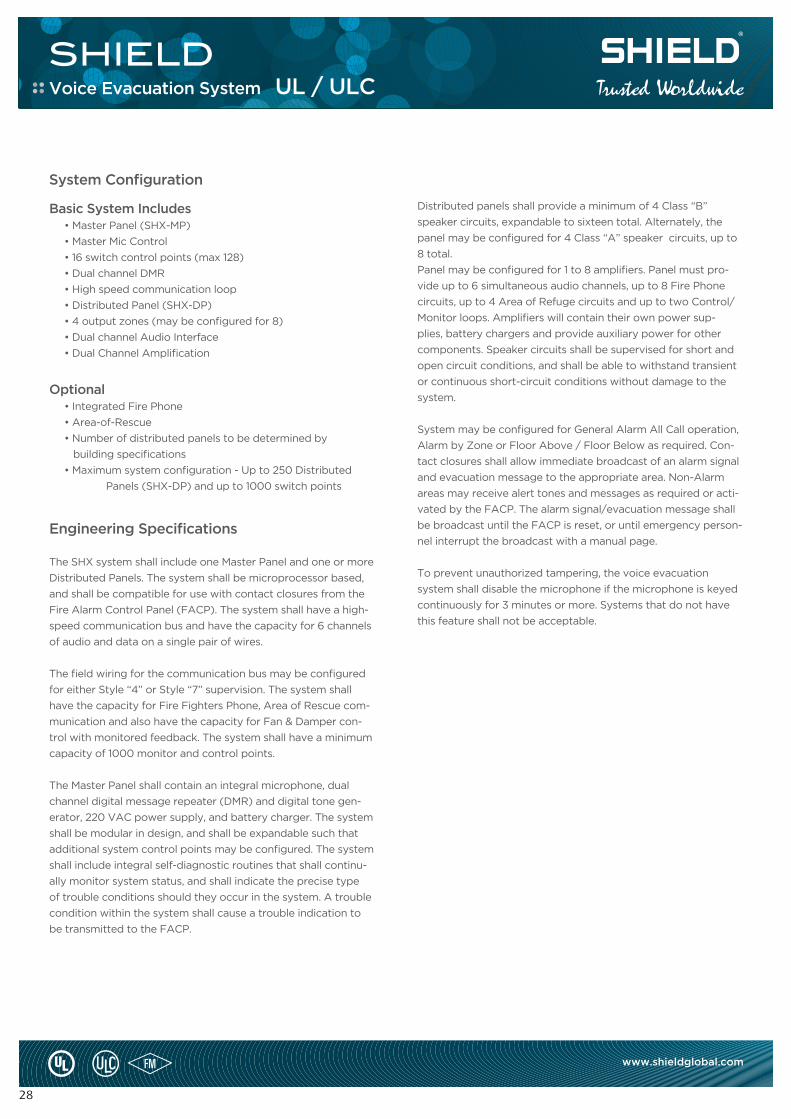
Basic System Includes• Master Panel (SHX-MP)
• Master Mic Control
• 16 switch control points (max 128)
• Dual channel DMR
• High speed communication loop
• Distributed Panel (SHX-DP)
• 4 output zones (may be configured for 8)
• Dual channel Audio Interface
• Dual Channel Amplification
Optional• Integrated Fire Phone
• Area-of-Rescue
• Number of distributed panels to be determined by
building specifications
• Maximum system configuration - Up to 250 Distributed
Panels (SHX-DP) and up to 1000 switch points
Engineering Specifications
The SHX system shall include one Master Panel and one or more
Distributed Panels. The system shall be microprocessor based,
and shall be compatible for use with contact closures from the
Fire Alarm Control Panel (FACP). The system shall have a high-
speed communication bus and have the capacity for 6 channels
of audio and data on a single pair of wires.
The field wiring for the communication bus may be configured
for either Style “4” or Style “7” supervision. The system shall
have the capacity for Fire Fighters Phone, Area of Rescue com-
munication and also have the capacity for Fan & Damper con-
trol with monitored feedback. The system shall have a minimum
capacity of 1000 monitor and control points.
The Master Panel shall contain an integral microphone, dual
channel digital message repeater (DMR) and digital tone gen-
erator, 220 VAC power supply, and battery charger. The system
shall be modular in design, and shall be expandable such that
additional system control points may be configured. The system
shall include integral self-diagnostic routines that shall continu-
ally monitor system status, and shall indicate the precise type
of trouble conditions should they occur in the system. A trouble
condition within the system shall cause a trouble indication to
be transmitted to the FACP.
System Configuration
Distributed panels shall provide a minimum of 4 Class “B”
speaker circuits, expandable to sixteen total. Alternately, the
panel may be configured for 4 Class “A” speaker circuits, up to
8 total.
Panel may be configured for 1 to 8 amplifiers. Panel must pro-
vide up to 6 simultaneous audio channels, up to 8 Fire Phone
circuits, up to 4 Area of Refuge circuits and up to two Control/
Monitor loops. Amplifiers will contain their own power sup-
plies, battery chargers and provide auxiliary power for other
components. Speaker circuits shall be supervised for short and
open circuit conditions, and shall be able to withstand transient
or continuous short-circuit conditions without damage to the
system.
System may be configured for General Alarm All Call operation,
Alarm by Zone or Floor Above / Floor Below as required. Con-
tact closures shall allow immediate broadcast of an alarm signal
and evacuation message to the appropriate area. Non-Alarm
areas may receive alert tones and messages as required or acti-
vated by the FACP. The alarm signal/evacuation message shall
be broadcast until the FACP is reset, or until emergency person-
nel interrupt the broadcast with a manual page.
To prevent unauthorized tampering, the voice evacuation
system shall disable the microphone if the microphone is keyed
continuously for 3 minutes or more. Systems that do not have
this feature shall not be acceptable.
Voice Evacuation System UL / ULC
SHIELD
29
www.shieldglobal.com
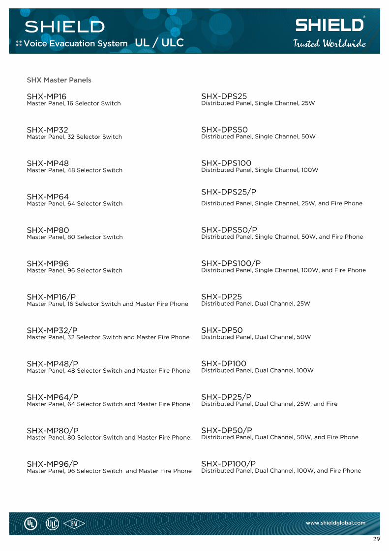
SHX Master Panels
SHX-MP16Master Panel, 16 Selector Switch
SHX-MP32Master Panel, 32 Selector Switch
SHX-MP48Master Panel, 48 Selector Switch
SHX-MP64Master Panel, 64 Selector Switch
SHX-MP80Master Panel, 80 Selector Switch
SHX-MP96Master Panel, 96 Selector Switch
SHX-MP16/PMaster Panel, 16 Selector Switch and Master Fire Phone
SHX-MP32/PMaster Panel, 32 Selector Switch and Master Fire Phone
SHX-MP48/PMaster Panel, 48 Selector Switch and Master Fire Phone
SHX-MP64/PMaster Panel, 64 Selector Switch and Master Fire Phone
SHX-MP80/PMaster Panel, 80 Selector Switch and Master Fire Phone
SHX-MP96/PMaster Panel, 96 Selector Switch and Master Fire Phone
SHX DISTRIBUTED PANELS
SHX-DPS25Distributed Panel, Single Channel, 25W
SHX-DPS50 Distributed Panel, Single Channel, 50W
SHX-DPS100Distributed Panel, Single Channel, 100W
SHX-DPS25/P
Distributed Panel, Single Channel, 25W, and Fire Phone
SHX-DPS50/PDistributed Panel, Single Channel, 50W, and Fire Phone
SHX-DPS100/PDistributed Panel, Single Channel, 100W, and Fire Phone
SHX-DP25Distributed Panel, Dual Channel, 25W
SHX-DP50Distributed Panel, Dual Channel, 50W
SHX-DP100Distributed Panel, Dual Channel, 100W
SHX-DP25/PDistributed Panel, Dual Channel, 25W, and Fire
SHX-DP50/PDistributed Panel, Dual Channel, 50W, and Fire Phone
SHX-DP100/PDistributed Panel, Dual Channel, 100W, and Fire Phone
Voice Evacuation System UL / ULC
SHIELD
30
www.shieldglobal.com
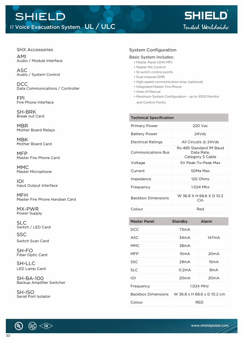
Technical Specification
Primary Power 220 Vac
Battery Power 24Vdc
Electrical Ratings All Circuits @ 24Vds
Communications BusRs-485 Standard 1M Baud
Data Rate, Category 5 Cable
Voltage 5V Peak-To-Peak Max
Current 50Ma Max
Impedance 120 Ohms
Frequency 1.024 Mhz
Backbox DimensionsW 36.8 X H 68.6 X D 10.2
Cm
Colour Red
Master Panel Standby Alarm
DCC 73mA
147mAASC 34mA
MMC 38mA
MFP 10mA 20mA
SSC 29mA 15mA
SLC 0.2mA 8mA
IOI 20mA 20mA
Frequency 1.024 MHz
Backbox Dimensions W 36.8 x H 68.6 x D 10.2 cm
Colour RED
Basic System Includes:• Master Panel (SHX-MP)
• Master Mic Control
• 16 switch control points
• Dual channel DMR
• High speed communication loop (optional)
• Integrated Master Fire Phone
• Area-of-Rescue
• Maximum System Configuration - up to 1000 Monitor
and Control Points.
System ConfigurationSHX Accessories
AMI Audio / Module Interface
ASCAudio / System Control
DCCData Communications / Controller
FPIFire Phone Interface
SH-BRKBreak out Card
MBRMother Board Relays
MBKMother Board Card
MFPMaster Fire Phone Card
MMCMaster Microphone
IOIInput Output Interface
MFHMaster Fire Phone Handset Card
MX-PWRPower Supply
SLCSwitch / LED Card
SSC Switch Scan Card
SH-FOFiber Optic Card
SH-LLCLED Lamp Card
SH-BA-100Backup Amplifier Switcher
SH-ISOSerial Port Isolator
Voice Evacuation System UL / ULC
SHIELD
31
www.shieldglobal.com
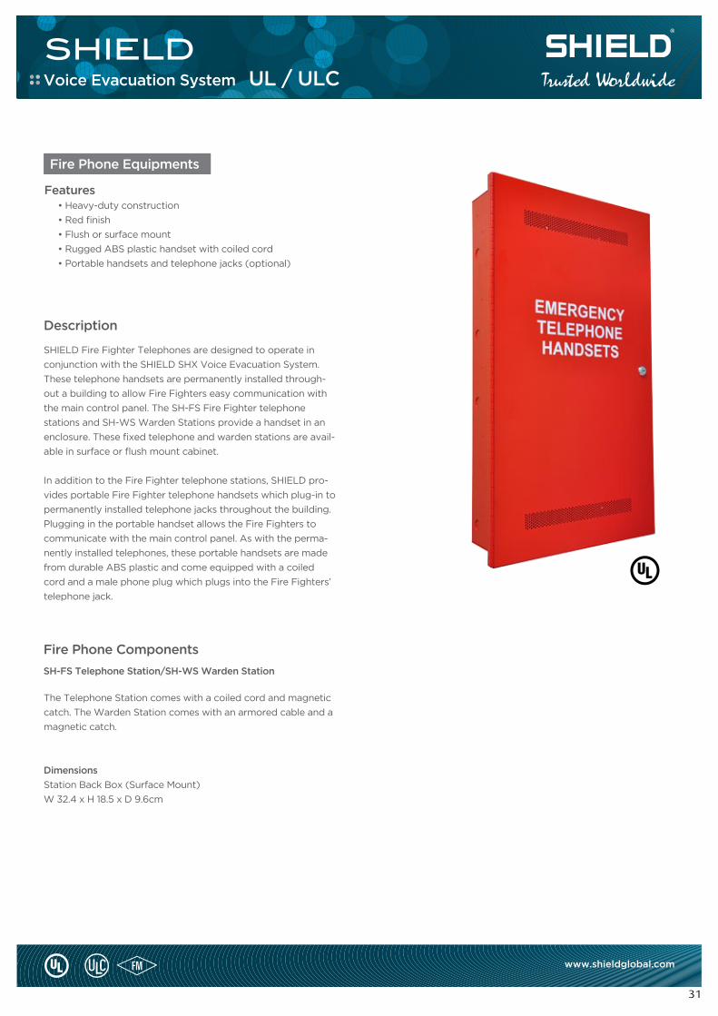
Features• Heavy-duty construction
• Red finish
• Flush or surface mount
• Rugged ABS plastic handset with coiled cord
• Portable handsets and telephone jacks (optional)
SHIELD Fire Fighter Telephones are designed to operate in
conjunction with the SHIELD SHX Voice Evacuation System.
These telephone handsets are permanently installed through-
out a building to allow Fire Fighters easy communication with
the main control panel. The SH-FS Fire Fighter telephone
stations and SH-WS Warden Stations provide a handset in an
enclosure. These fixed telephone and warden stations are avail-
able in surface or flush mount cabinet.
In addition to the Fire Fighter telephone stations, SHIELD pro-
vides portable Fire Fighter telephone handsets which plug-in to
permanently installed telephone jacks throughout the building.
Plugging in the portable handset allows the Fire Fighters to
communicate with the main control panel. As with the perma-
nently installed telephones, these portable handsets are made
from durable ABS plastic and come equipped with a coiled
cord and a male phone plug which plugs into the Fire Fighters’
telephone jack.
The Telephone Station comes with a coiled cord and magnetic
catch. The Warden Station comes with an armored cable and a
magnetic catch.
Dimensions
Station Back Box (Surface Mount)
W 32.4 x H 18.5 x D 9.6cm
Description
Fire Phone Components
SH-FS Telephone Station/SH-WS Warden Station
Fire Phone Equipments
Voice Evacuation System UL / ULC
SHIELD
32
www.shieldglobal.com
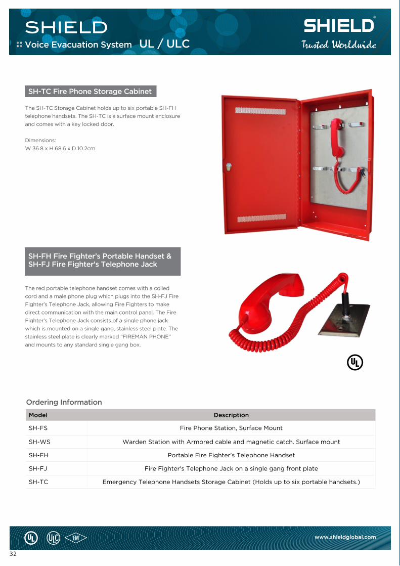
SH-TC Fire Phone Storage Cabinet
SH-FH Fire Fighter’s Portable Handset & SH-FJ Fire Fighter’s Telephone Jack
The SH-TC Storage Cabinet holds up to six portable SH-FH
telephone handsets. The SH-TC is a surface mount enclosure
and comes with a key locked door.
Dimensions:
W 36.8 x H 68.6 x D 10.2cm
The red portable telephone handset comes with a coiled
cord and a male phone plug which plugs into the SH-FJ Fire
Fighter’s Telephone Jack, allowing Fire Fighters to make
direct communication with the main control panel. The Fire
Fighter’s Telephone Jack consists of a single phone jack
which is mounted on a single gang, stainless steel plate. The
stainless steel plate is clearly marked “FIREMAN PHONE”
and mounts to any standard single gang box.
Ordering Information
Model Description
SH-FS Fire Phone Station, Surface Mount
SH-WS Warden Station with Armored cable and magnetic catch. Surface mount
SH-FH Portable Fire Fighter's Telephone Handset
SH-FJ Fire Fighter's Telephone Jack on a single gang front plate
SH-TC Emergency Telephone Handsets Storage Cabinet (Holds up to six portable handsets.)
Voice Evacuation System UL / ULC

Model Description
SH-FS Fire Phone Station, Surface Mount
SH-WS Warden Station with Armored cable and magnetic catch. Surface mount
SH-FH Portable Fire Fighter's Telephone Handset
SH-FJ Fire Fighter's Telephone Jack on a single gang front plate
SH-TC Emergency Telephone Handsets Storage Cabinet (Holds up to six portable handsets.)

SHIELD FIRE, SAFETY AND SECURITY LTDRedburn House, 2A Tonbridge Road, Romford, Essex – RM3 8QE, United KingdomTel: +44 1708 377731, Fax: +44 1708 347637, E-mail: [email protected]
www.shieldglobal.com
Recommended