8.2 Finite element modeling of laser assisted friction stir welding of carbon steels for enhanced sustainability of welded joints
A. H. Kheireddine, A. H. Ammouri, R. F. Hamade
Department of Mechanical Engineering, American University of Beirut (AUB), Beirut, Lebanon
Abstract
In Friction stir welding (FSW) of carbon steels, process parameters must be set to avoid defects such as warm
holes. Proper selection of process parameters also affects the final grain microstructure and phase
transformations and, ultimately, the weld’s mechanical properties. Process parameters, including laser-
assisted heating, of AISI 1045 carbon steel were investigated via a 3D finite element method (FEM) model.
The laser action was modeled as heat source with constant flux. The simulation findings favorably agree with
experiments reported in the literature and suggesting that with laser-assisted-FSW welding can be performed
at higher traverse speeds (400 vs. 100 mm/min) while maintaining defect free weld. Also, evolved phase
transformations are predicted across the weld geometry as time progresses. Such findings will help in the
prediction of sound welding parameters and in estimating the mechanical properties of the various regions of
the weld leading to more sustainable joints.
Keywords:
FEM; Simulations, Friction stir welding; Laser.
1 INTRODUCTION
Friction stir welding (FSW) is a solid state joining process that
utilizes a rapidly-rotating, high strength steel tool in the form
of a pin inserted along the weld steam to join similar or
dissimilar metals. Known problems associated with friction stir
welding (FSW) may be alleviated by the proper selection of
process parameters leading to more sustainable processing
and to enhanced welded joints. Such parameters include tool
feed, spindle speed, tool geometry, tool tilt angle, and in-
process cooling or heating. The proper selection of such
factors is a key for achieving defect-free welds by avoiding
defects such as warm holes and voids. Furthermore,
achieving desirable grain size at the weld as well as the final
phases also results from the combination of the process
parameters which must be carefully defined in order to
achieve target results.
FSW is considered a hot-working process in which massive
plastic deformation occurs through the rotating pin without
subjecting the workpiece to any form of induced heating or
melting. Such deformation gives rise to a
thermomechanically-affected rejoin (TMAZ) and a heat-
affected zone (HAZ) [1]. During the welding process, the
material is wiped from the front side of the pin onto the back
side in a helical motion within the stir zone [2]. Among the
advantages of Friction stir welding is the ability of this
technique to efficiently control the cooling rate and peak
temperature by varying the speed of the rotating pin [3]. FSW
is used in joining metals of poor weldability and in many
green applications [4]. Friction stir welding is heavily used in
the aerospace industry to join, for example, high strength
aluminum alloys that are hard to weld using traditional
welding techniques. For steel and other high-temperature
materials, the application of FSW is limited to the presence of
suitable tools that can operate in the temperature range of
1000 to 1200 °C [5]. This is due to the fact that the heat
produced by stirring and friction may not be sufficient to
soften the material around the rotating tool. Therefore, it is
important to select tool materials with good wear resistance
and toughness at temperatures of 1000°C or higher [4].
However, in the past few years, studies have reported to the
effect that FSW is capable of achieving grain improvements in
the stir zone in steels similar to those observed in light metals
such as aluminum. A number of studies that tackle
microstructural changes during FSW have been conducted to
examine the influence of the welding parameters on material
flow and the shape of the interface between the various
zones. One such study [6] modeled friction stir welding of
stainless steel (304L) utilizing the finite element method
(FEM) and using an Eulerian formulation with coupled
viscoplastic flow and heat transfer around the tool pin. Some
of the findings were that: higher temperatures on the
advancing side compared to the retreating side, higher
strength in the weld zone compared to the base material,
harder friction stirred zones compared to the unreformed
base metals, highest effective stress in the stirred zone, more
anisotropy in the material near the friction stirred zone than
the material passing farther from the tool pin. The
microstructure and mechanical properties of welded joints are
significantly affected by such parameters as heat input during
welding, the composition of steel metal used, and the in-
process cooling and heating of the welded zone [7]. In-
process laser heating was introduced in [8] where a laser
beam was used as a preheating source during friction stir
welding. Preheating in this process aids in softening the metal
before stirring and thus increasing the speed of the rotating
tool and less work is now required by the tool to raise the
temperature of the workpiece. Using this technique the heat
generated by the tool is reduced and the tool life is increased.
Moreover, the higher rotational speeds and the higher cooling
rates attained (above 600 mm/min) by laser-assisted FSW
prevented the formation of brittle martensite which increases
the hardness of the welded zone [9]. For more sustainable
laser-assisted friction stir welding processes, the process will
have to capture some of the elements defined in [10] to
characterize sustainability: (1) power consumption, (2)
operational safety, (3) personnel health, (4) environmental
impact, (5) manufacturing costs and (6) waste management.
G. Seliger (Ed.), Proceedings of the 11th Global Conference on Sustainable Manufacturing - Innovative Solutions
ISBN 978-3-7983-2609-5 © Universitätsverlag der TU Berlin 2013
247
A. H. Kheireddine, A. H. Ammouri, R. F. Hamade
Although laser assisted FSW requires higher power inputs but
with preheating higher production rates can be achieved thus
decreasing the total production costs. Moreover, it is believed
that achieving a better quality product especially through
enhancing surface integrity is a main aspect of manufacturing
sustainability. Using preheating in FSW through laser beam
was found [11] to enhance surface integrity through
increasing the surface hardness via refined microstructure
evolution. In addition to that the approach followed which is
numerical simulation for optimization purposes is proven to
decrease costs relative to experimental approaches. In this
paper, a finite element model was developed to simulate the
Laser-assisted FSW and optimize the process parameters to
enhance surface integrity and microstructural properties
which affect the tool ware resistance and as a result the
sustainability of the process. The commercial modelling
software DEFORM-3D™ (Scientific Forming Technologies
Corporation, 2545 Farmers Drive, Suite 200, Columbus, Ohio
43235) was used as a fully thermo-mechanically coupled FE
model to simulate the process. The model accounted for
phase transformation taking place and was validated against
experimental data.
2 THE FEM MODEL
2.1 Parts and Meshes
A thermo-mechanically coupled model using the FE software
DEFORM was implemented to model the friction stir welding
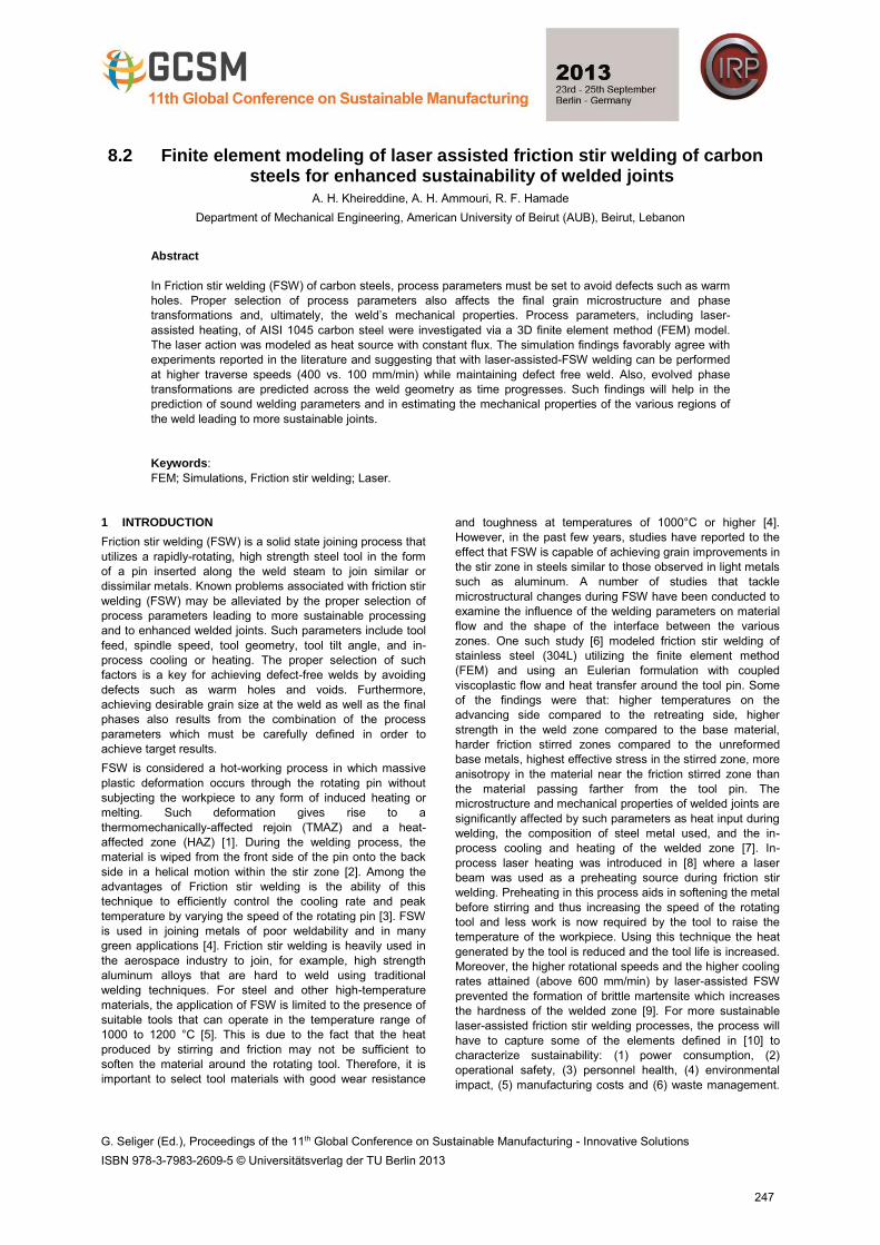
of carbon steel. As shown in figure 1, the model comprises
the tool, the workpiece, and the backing plate. Also shown
superimposed on the meshed geometry is a rendering of the
in-process laser source. To model the laser source, a heat
source circular window with constant heat flux was defined.
The circular window is of diameter 2 mm and is placed 5 mm
in front of the tool. The power of the laser was 2kW.
Both the tool and the backing plate were modeled as rigid un-
deformable bodies where only heat transfer was accounted.
On the other hand the workpiece was modeled as a plastic
body subject to deformation and heat. The two plates to be
welded were modeled as one block to avoid numerical
instabilities at the contact.
Figure 1: The meshed FE model showing the tool, workpiece,
and backing plate (under the workpiece). Shown
superimposed is a rendering of the in-process laser source.
The considered tool was a cylindrical shoulder 15mm in
diameter. From the bottom of the shoulder, a 6 mm diameter
smooth unthreaded pin extrudes 3.2 mm. The tool was tilted
3° about the vertical axis in the processing direction to further
improve material flow. Both the workpiece and the backing
plate had an area of 60x40 mm2 and a thickness of 3.2 mm.
Tetrahedral elements were used in the FEM model. The tool
and the backing plate were meshed for thermal analysis
purposes only with each containing around 10000 and 5000
elements respectively while the workpiece had around 24000
elements. To further capture the state variables at the tool-
workpiece interface, a rectangular mesh control window was
applied around the processing area of interest where finer
mesh elements (around 0.3 mm) were created as shown in
Figure 6.
2.2 Material Modeling
The material used for the tool and the backing plate was WC
based alloy. As for the workpiece, it is believed that the final
weld mechanical properties are strictly dependent on the
volume fraction of phases present. Therefore, AISI 1045
(workpiece material) was defined as a mixture of phases.
Specifically three phases were defined: martensite, austenite,
and pearlite. The transformation to any of the phases was
defined according phase transformation, isothermal, and
continuous cooling transformation diagrams. The functions
recommended by DEFORM are listed below in Table 1 and
which were used along with the appropriate generated latent
heat values. The initial volume fraction of the elements was
defined as 100 percent pearlite which is predominatly the
case of as received mild-carbon steels. Each phase has its
own materiel properties which are, in turn, function of
temperature. Similarly, each of the phases has its own flow
stress equation. The linear hardening equation used to
formulate the stress equation was
where,
A = Atom content
T = Temperature
ε ̅= Effective plastic strain
σ ̅= Flow stress
Y = Initial yield stress (temperature dependent)
H = Strain hardening (temperature dependent)
Table 1: Phase Transformation Models
Phase 1 Phase 2 Transformation
Model
Austenite Martensite Magee's Equation Austenite Pearlite Diffusion(TTT curve)
Martensite Austenite Diffusion(Simplified) Pearlite Austenite Diffusion(Simplified)
2.3 Friction Modeling
Friction at the tool-workpiece interface is a very complex
process due to the variation of temperature, strain rate, and
stress which make friction modeling a difficult task. In [12] a
numerical model with experimental evidence was developed
to estimate the shear friction coefficient in FSW. The model
uses the tool speed and dimensions to estimate the shear
friction coefficient as shown below:
σ̅ = Y(T, A) + H(T, A)ε̅ (1)
248
Finite element modeling of laser assisted friction stir welding of carbon steels for enhanced sustainability of welded joints
μf= μ0 exp(-λδωr) (2)
where δ is the percentage sticking and r is the radial distance
from the tool axis for the point in consideration. The values
used were as follows: μ0= 0.4, δ= 0.4, ω=62.8 radians, r=
0.003m and constant λ was 1s/m [12].
2.4 Boundary Conditions
Heat transfer with the environment was accounted for the
three meshed objects (tool, workpiece, and backing plate) via
a convective heat coefficient of 20 W/(m2 ºC) at a constant
temperature set at 293K for the surrounding environment.
The heat transfer coefficient between the tool-workpiece and
the backing plate-workpiece interfaces was set to 11
kW/(m2ºC). Local re-meshing was triggered by a relative
interference ratio of 70% between contacting edges. This
would ensure the integrity of the workpiece geometry during
deformation. The simulation time step selection should be
optimized to prevent redundant calculations while preserving
the state variables’ accuracy. The time step in the simulation
was determined based on the tool rotational speed and the
minimum element size to guarantee a calculation step every 5
degrees of the tool rotation. Simulation time was further
reduced by neglecting the plunging phase of FSW and taking
into consideration the traversing phase alone. The tool final
plunged shape was cut from the workpiece geometric model
to account for the deformation produced by the plunging
phase. A dwelling phase was added at the beginning of each
run where the tool spins in its place to raise the temperature
at the stir zone to the plunging elevated levels. In tool
movement definition, a trapezoidal speed profile with a rise
time of 0.5s was used. This would ensure a smooth
processing start and prevent voids during the plunging stage.
3 MODEL VALIDATION
The FEM model was validated against experimental data available in the literature by tracking the temperature history of an observation point at the seam line at a distance of 0.5 mm above the shoulder for two different test cases. The processing parameters of both cases are described in table 2.
Table 2: Processing parameters of the validation test cases
Property Case 1 Case 2
Rotational speed (RPM) 600 600
Traverse speed (mm/min) 100 400
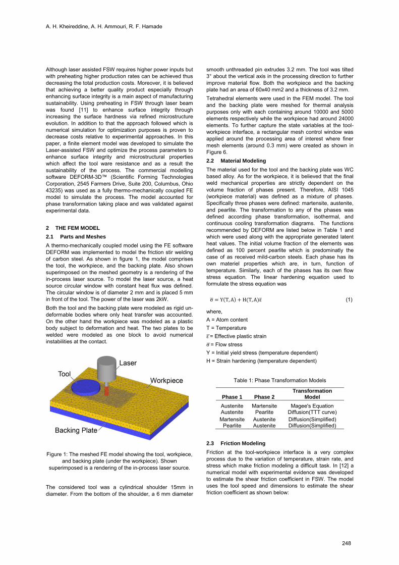
Figure 2: Temperature contour plot in workpiece for case 2
(rotational spindle speed = 600 rpm, traverse speed = 400
mm/min) after 6 seconds of welding
Figure 2 shows the temperature contours for case 2
(rotational spindle speed = 600 rpm, traverse speed = 400
mm/min) where peak temperature is located at the pin/tool
interface as one would normally expect in an FSW process.
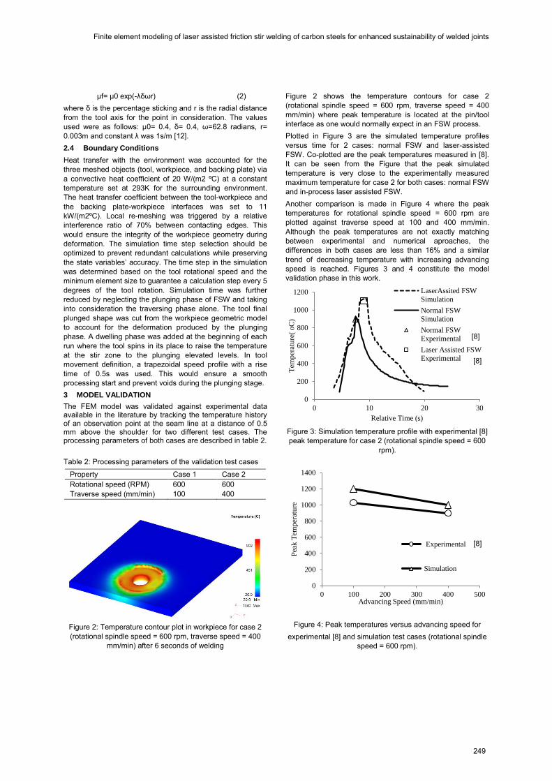
Plotted in Figure 3 are the simulated temperature profiles
versus time for 2 cases: normal FSW and laser-assisted
FSW. Co-plotted are the peak temperatures measured in [8].
It can be seen from the Figure that the peak simulated
temperature is very close to the experimentally measured
maximum temperature for case 2 for both cases: normal FSW
and in-process laser assisted FSW.
Another comparison is made in Figure 4 where the peak
temperatures for rotational spindle speed = 600 rpm are
plotted against traverse speed at 100 and 400 mm/min.
Although the peak temperatures are not exactly matching
between experimental and numerical aproaches, the
differences in both cases are less than 16% and a similar
trend of decreasing temperature with increasing advancing
speed is reached. Figures 3 and 4 constitute the model
validation phase in this work.
Figure 3: Simulation temperature profile with experimental [8]
peak temperature for case 2 (rotational spindle speed = 600
rpm).
Figure 4: Peak temperatures versus advancing speed for
experimental [8] and simulation test cases (rotational spindle
speed = 600 rpm).
0
200
400
600
800
1000
1200
0 10 20 30
Tem
per
atu
re(
oC
)
Relative Time (s)
LaserAssited FSW
Simulation
Normal FSW
Simulation
Normal FSW
Experimental
Laser Assisted FSW
Experimental
0
200
400
600
800
1000
1200
1400
0 100 200 300 400 500
Pea
k T
emp
erat
ure
Advancing Speed (mm/min)
Experimental [9]
Simulation
[8]
[24]
[8]
[8]
249
A. H. Kheireddine, A. H. Ammouri, R. F. Hamade
4 RESULTS
4.1 Phase transformations
The resulting mechanical properties of carbon steel joints
ultimately depend on the intermetallic phases present and,
thus, on the heating and cooling histories during the process.
During FSW of carbon steels, temperature exceeds the
transition temperature (about 727 oC for many steels) at
which austenite begins to form upon heating. Therefore,
transformations form austenite to other forms such as
pearlite, martensite, and bainite will take place afterwards.
Furthermore, the amount and type of these transformations is
directly affected by the maximum temperature (mostly related
to rotational speed) and cooling rate (mostly related to
advancing speed). Other external heating (e.g., laser) and
cooling (cryogenic) sources during FSW/FSP also play a
critical role in altering these phase transformations and the
resulting grain size for many materials [13,14].
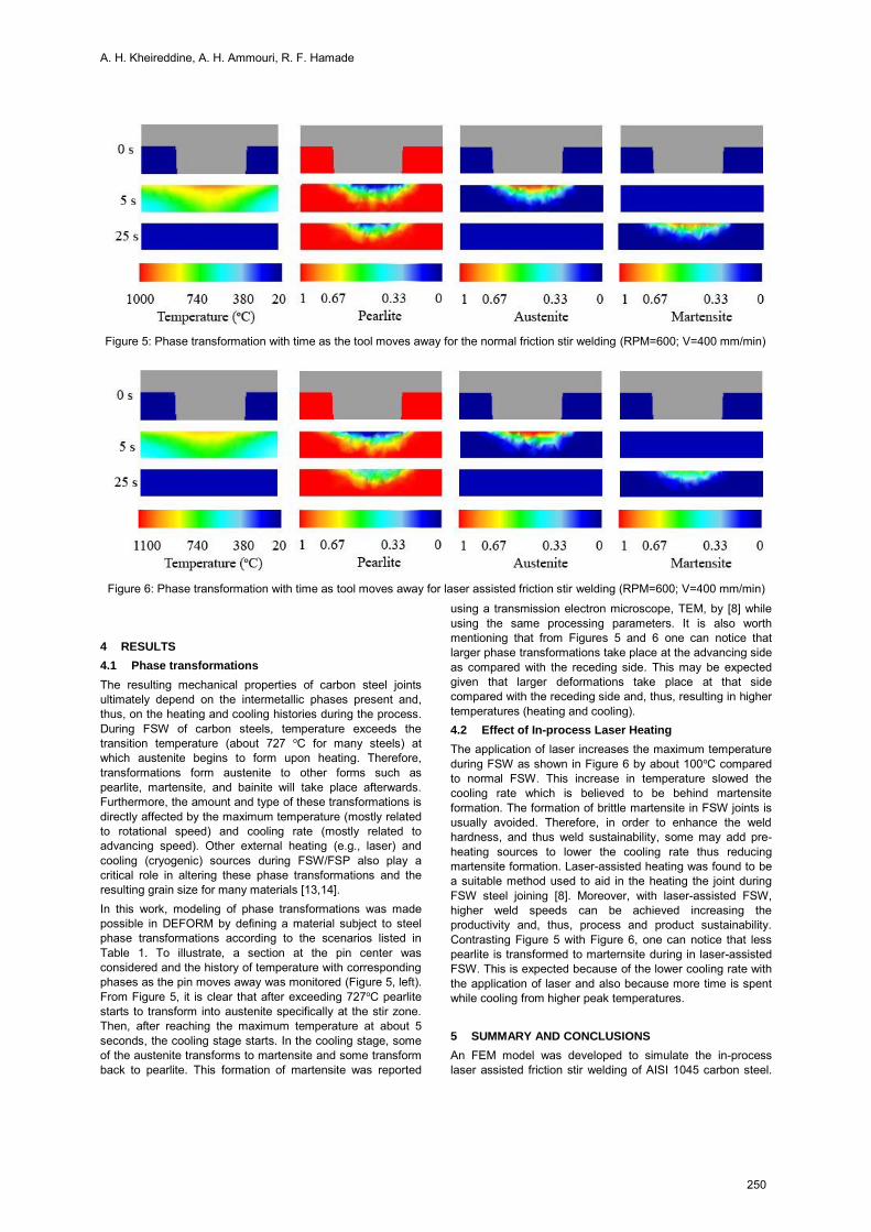
In this work, modeling of phase transformations was made
possible in DEFORM by defining a material subject to steel
phase transformations according to the scenarios listed in
Table 1. To illustrate, a section at the pin center was
considered and the history of temperature with corresponding
phases as the pin moves away was monitored (Figure 5, left).
From Figure 5, it is clear that after exceeding 727oC pearlite
starts to transform into austenite specifically at the stir zone.
Then, after reaching the maximum temperature at about 5
seconds, the cooling stage starts. In the cooling stage, some
of the austenite transforms to martensite and some transform
back to pearlite. This formation of martensite was reported
using a transmission electron microscope, TEM, by [8] while
using the same processing parameters. It is also worth
mentioning that from Figures 5 and 6 one can notice that
larger phase transformations take place at the advancing side
as compared with the receding side. This may be expected
given that larger deformations take place at that side
compared with the receding side and, thus, resulting in higher
temperatures (heating and cooling).
4.2 Effect of In-process Laser Heating
The application of laser increases the maximum temperature
during FSW as shown in Figure 6 by about 100oC compared
to normal FSW. This increase in temperature slowed the
cooling rate which is believed to be behind martensite
formation. The formation of brittle martensite in FSW joints is
usually avoided. Therefore, in order to enhance the weld
hardness, and thus weld sustainability, some may add pre-
heating sources to lower the cooling rate thus reducing
martensite formation. Laser-assisted heating was found to be
a suitable method used to aid in the heating the joint during
FSW steel joining [8]. Moreover, with laser-assisted FSW,
higher weld speeds can be achieved increasing the
productivity and, thus, process and product sustainability.
Contrasting Figure 5 with Figure 6, one can notice that less
pearlite is transformed to marternsite during in laser-assisted
FSW. This is expected because of the lower cooling rate with
the application of laser and also because more time is spent
while cooling from higher peak temperatures.
5 SUMMARY AND CONCLUSIONS
An FEM model was developed to simulate the in-process
laser assisted friction stir welding of AISI 1045 carbon steel.
Figure 5: Phase transformation with time as the tool moves away for the normal friction stir welding (RPM=600; V=400 mm/min)
Figure 6: Phase transformation with time as tool moves away for laser assisted friction stir welding (RPM=600; V=400 mm/min)
250
Finite element modeling of laser assisted friction stir welding of carbon steels for enhanced sustainability of welded joints
The simulation results of peak temperatures of the weld were
validated against experimental work reported by other
researchers [8]. The effect of advancing speed on weld
temperature was examined where peak temperatures were
found to decrease with increasing traverse welding speed.
With laser assistance, however, higher welding temperatures
can now be reached faster at higher welding speeds thus
increasing the sustainability of the process. Furthermore, the
resulting phase transformations, which have direct effect on
the microstructure and, thus, the mechanical properties of the
weld were successfully accounted in the model. It was found
that with laser-assisted processing, smaller phase fraction of
the brittle martensite phase is formed at the stir zone resulting
in enhanced properties of the welded joint and, thus,
enhancing weld sustainability. It is believed that such model
can be used for optimization purposes leading to more
sustainable processes and, more importantly, sustainable
products.
6 ACKNOWLEDGMENTS
This publication was made possible by the National Priorities
Research Program (NPRP) grant # 09-611-2-236 from the
Qatar National Research Fund (a member of The Qatar
Foundation). The statements made herein are solely the
responsibility of the authors. The second author gratefully
acknowledges the support of Consolidated Contractors
Company (CCC) through the CCC Doctoral Fellowship in
Manufacturing.
7 REFERENCES
[1]. K.V. Jata and S.L. Semiatin. 2000. Continues dynamic
recrystallization during friction stir welding of high
strength aluminum alloys. Scripta mater 43 (2000) 743-
749.
[2]. M. Guerra, C. Schmidt, J.C. McClure, L.E. Murr, A.C.
Nunes, 2002. Flow patterns during friction stir welding.
Materials Characterization 49 (2003) 95–101.
[3]. L. Cui, H. Fujii, N. Tsuji, K. Nogi.2007. Friction stir
welding of a high carbon steel. Scripta Materialia 56
(2007) 637–640.
[4]. R. Mishra, Z. Ma. 2005. Friction stir welding and
processing. Materials Science and Engineering R 50
(2005) 1–78.
[5]. A. Ozekcin, H. Jin, J. Koo, N. Bangaru, R. Ayer. 2004. A
Microstructural Study of Friction Stir Welded Joints of
Carbon Steels. International Journal of Offshore and
Polar Engineering.
[6]. J Cho, Donald E. Boyce, P. Dawson. 2005. Modeling
strain hardening and texture evolution in friction stir
welding of stainless steel. Materials Science and
Engineering A 398 (2005) 146–163.
[7]. H. Fujii, L. Cui, N. Tsuji, M. Maeda, K. Nakata, K.
Nogi.2006. Friction stir welding of carbon steels.
Materials Science and Engineering A 429 (2006) 50–57.
[8]. Y. Sun, Y. Konishi, M. Kamai, H. Fujii. Microstructure and mechanical properties of S45C steel prepared by
laser-assisted friction stir welding. Materials and Design
47 (2013) 842–849. Ueji R, Fujii H, Cui L, Nishioka A,
Kunishige K, Nogi K. Friction stir welding of ultrafine
grained plain low-carbon steel formed by the Martensite
process. Mater Sci Eng A 2006;423(1–2):324–30
[9]. Jawahir, I.S. and Dillon, O.J., 2007, Sustainable
Manufacturing Processes: New Challenges for
Developing Predictive Models and Optimization
Techniques, (Keynote Paper), Proc. 1st International
Conference on Sustainable Manufacturing (SM1),
Montreal, Canada, October 18-19, 2007, pp. 1-19.
[10]. Jawahir, I.S, Brinksmeier, E., M’Saoubi, R., Aspinwall,
D.K., Outerio, J.C., Meyer, D., Umbrello, D., Jayal, A.D.,
2011, Surface Integrity in material removal process:
Recent Advances, CIRP Annals – Manufacturing
Technology, 60:603-626.
[11]. Buffa, G., Fratini, L., and Shivpuri, R., 2007, "CDRX
Modelling in Friction Stir Welding of AA7075-T6
Aluminum Alloy: Analytical Approaches," Journal of
Materials Processing Technology, 191(1-3) pp. 356-359.
[12]. Nandan, R., Prabu, B., De, A., & Debroy, T., 2007,
Improving reliability of heat transfer and materials flow
calculations during friction stir welding of dissimilar
aluminum alloys. WELDING JOURNAL-NEWYORK-,
86(10), 313.
[13]. A.H. Kheireddine, A. H. Ammouri, R. F. Hamade, G. T.
Kridli, 2012, FEM analysis of the effects of cooling
techniques on the microstructure of aluminum 7075
friction stir welded joints, IMECE2012-88943,
proceedings of the ASME 2012 International Mechanical
Engineering Congress & Exposition, IMECE2012,
November 9-15, 2012, Houston, Texas, USA
[14]. A. H. Ammouri, A. H. Kheireddine, R. F. Hamade, G. T.
Kridli, 2013, FEM optimization of process parameters
and in-process cooling in the friction stir processing of
magnesium alloy az31b, IMECE2013-62468, ASME
2013 International Mechanical Engineering Congress &
Exposition, IMECE2013, Nov 15-21, 2013, San Diego,
USA.
251
Recommended