7/26/2019 Fig 260 Insulation Saddles
http://slidepdf.com/reader/full/fig-260-insulation-saddles 1/4
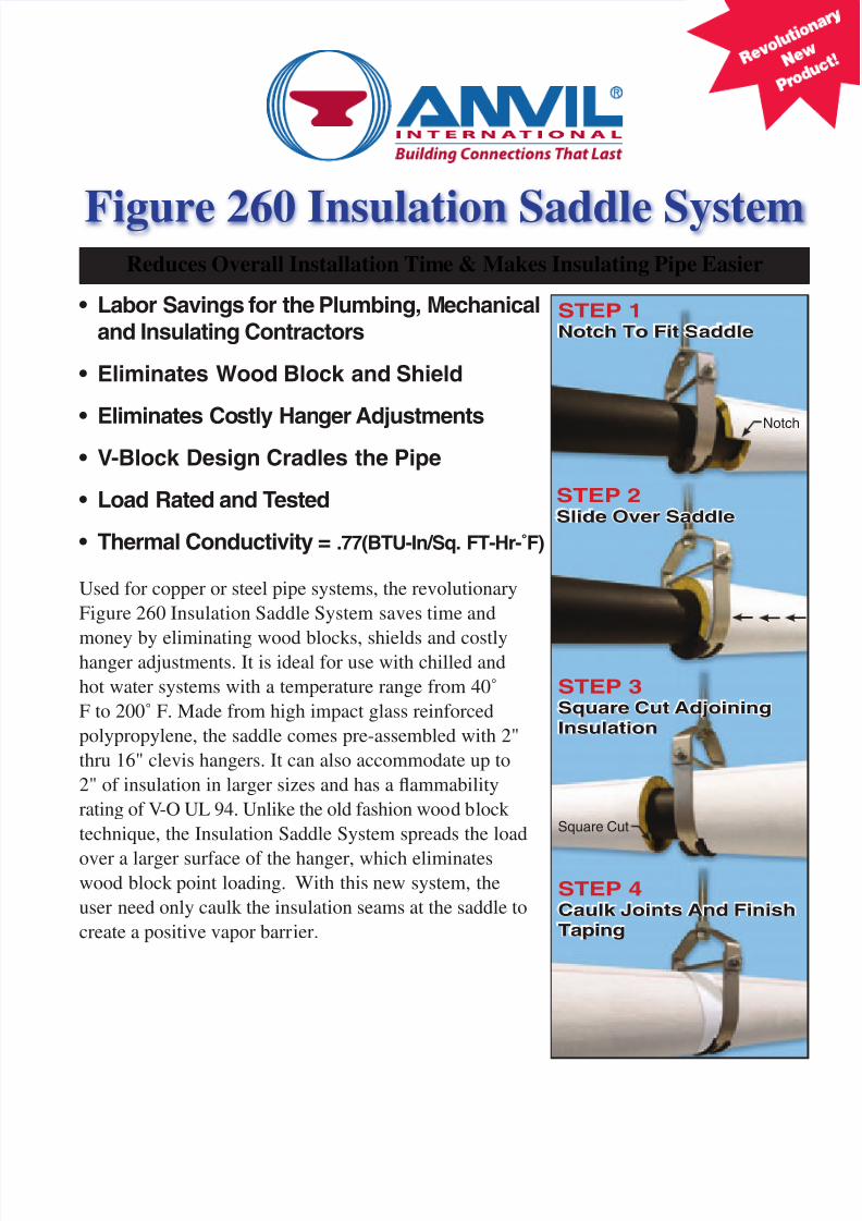
Figure 260 Insulation Saddle SystemReduces Overall Installation Time & Makes Insulating Pipe Easier
Used for copper or steel pipe systems, the revolutionary
Figure 260 Insulation Saddle System saves time and
money by eliminating wood blocks, shields and costlyhanger adjustments. It is ideal for use with chilled and
hot water systems with a temperature range from 40˚
F to 200˚ F. Made from high impact glass reinforced
polypropylene, the saddle comes pre-assembled with 2"
thru 16" clevis hangers. It can also accommodate up to
2" of insulation in larger sizes and has a flammability
rating of V-O UL 94. Unlike the old fashion wood block
technique, the Insulation Saddle System spreads the load
over a larger surface of the hanger, which eliminateswood block point loading. With this new system, the
user need only caulk the insulation seams at the saddle to
create a positive vapor barrier.
STEP 1Notch To Fit Saddle
STEP 2Slide Over Saddle
STEP 3Square Cut AdjoiningInsulation
STEP 4Caulk Joints And FinishTaping
• Labor Savings for the Plumbing, Mechanicaland Insulating Contractors
• Eliminates Wood Block and Shield
• Eliminates Costly Hanger Adjustments
• V-Block Design Cradles the Pipe
• Load Rated and Tested
• Thermal Conductivity = .77(BTU-In/Sq. FT-Hr-˚F)
Notch
Square Cut
7/26/2019 Fig 260 Insulation Saddles
http://slidepdf.com/reader/full/fig-260-insulation-saddles 2/4
Figure 260 (ISS) Insulation Saddle System
Size Range:2" through 16" Clevis Hanger with Saddle Assembly1 / 2" through 12" Pipe Diameter
Material: Carbon Steel with High Impact GlassReinforced Polypropylene Saddle and Carbon Steel PipeSpacer.
Finish: Plain or Galvanized Clevis Hanger
Service: Recommended for the suspension of StationaryInsulated Chilled or Hot Water Pipe Lines.
Maximum Temperature: 40˚F to 200˚F
How to Size: Hanger must be selected from the sizingtable according to pipe size and insulation thickness.
Installation: Hanger load nut above clevis must betightened securely to assure proper performance. Installthe pipe on the saddle. Cope or notch one section ofinsulation to securely fit around the saddle. Notch should
be deep enough to extend 1 / 8" to 1 / 4" beyond the saddle.Square cut adjoining insulation section and butt themating end to the notched section. Apply mastic to allmating insulation edges, caulk all seams between insula-tion and saddle as applicable to chilled or hot water systemsto assure positive vapor barrier. Finish via standardtaping methods.
Adjustments: Vertical adjustment without removingthe hanger may be made 7 / 8" through 23 / 8" varying withthe size of the clevis. Tighten all nuts after adjustment.
Features: Clevis Hanger with High Impact Saddle
eliminates costly hanger adjustments required during theinstallation of piping insulation. Wood blocks and shieldsare not required for use with this product. V-Block designcradles the pipe during and after installation. Low ther-mal conductivity calculated at .77 (BTU-In/Sq. Ft-Hr-˚F).Flammability rating of V-O UL 94.
Ordering:Specify size number, insulation thickness, figure numberand finish.
Fig. 260 (ISS) Insulation Saddle System Pricing
Size Plain Galvanized
2 $33.04 $36.003 $39.08 $44.204 $54.20 $62.005 $79.32 $88.806 $90.00 $105.808 $115.20 $139.60
10 $192.40 $227.8012 $248.80 $300.4014 $294.68 $352.8016 $441.36 $543.00
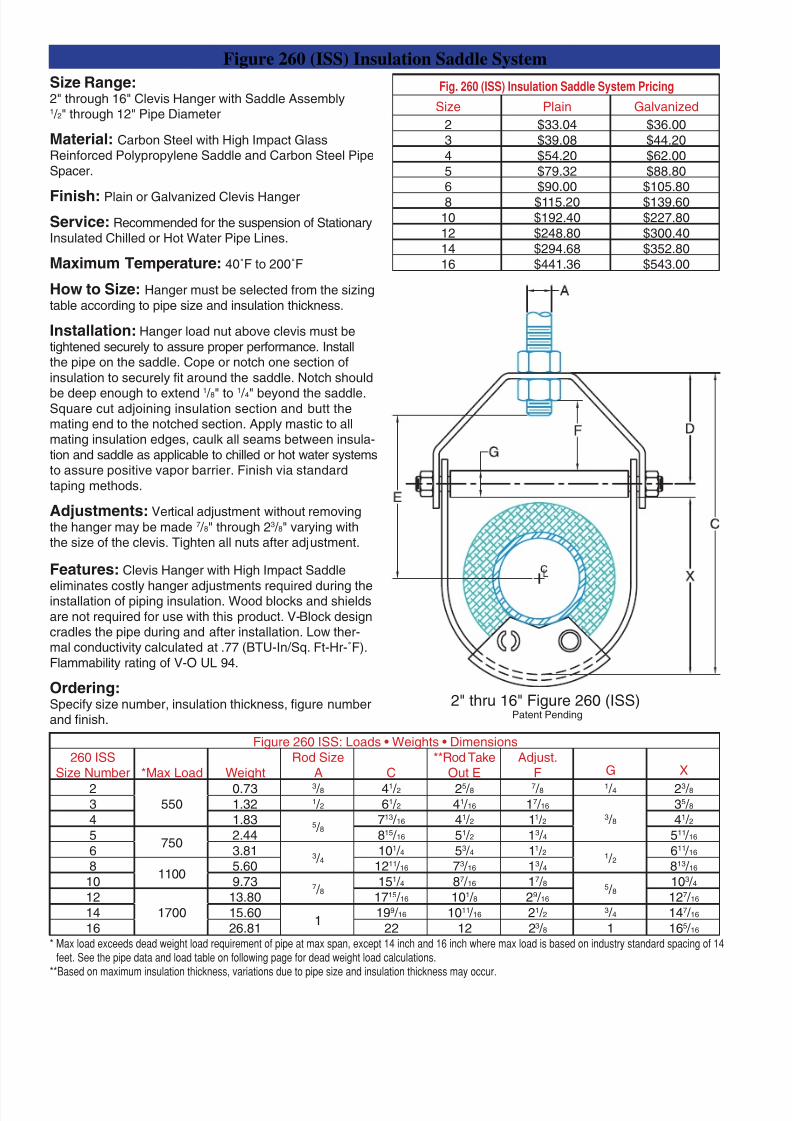
Figure 260 ISS: Loads • Weights • Dimensions260 ISS
Size Number *Max Load WeightRod Size
A C**Rod Take
Out EAdjust.
F G X
2550
0.73 3 / 8 41 / 2 25 / 8 7 / 8 1 / 4 23 / 83 1.32 1 / 2 61 / 2 41 / 16 17 / 16
3 / 835 / 8
4 1.83 5 / 8713 / 16 41 / 2 11 / 2 41 / 2
5750
2.44 815 / 16 51 / 2 13 / 4 511 / 16
6 3.81 3 / 4101 / 4 53 / 4 11 / 2 1 / 2
611 / 16
81100
5.60 1211 / 16 73 / 16 13 / 4 813 / 16
10 9.73 7 / 8151 / 4 87 / 16 17 / 8 5 / 8
103 / 412
170013.80 1715 / 16 101 / 8 29 / 16 127 / 16
14 15.601
199 / 16 1011 / 16 21 / 2 3 / 4 147 / 16
16 26.81 22 12 23 / 8 1 165 / 16
* Max load exceeds dead weight load requirement of pipe at max span, except 14 inch and 16 inch where max load is based on industry standard spacing of 14feet. See the pipe data and load table on following page for dead weight load calculations.
**Based on maximum insulation thickness, variations due to pipe size and insulation thickness may occur.
2" thru 16" Figure 260 (ISS)Patent Pending
7/26/2019 Fig 260 Insulation Saddles
http://slidepdf.com/reader/full/fig-260-insulation-saddles 3/4
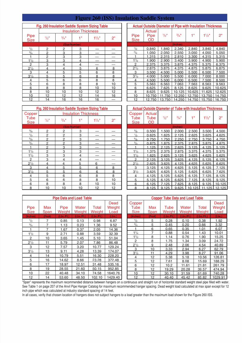
Fig. 260 Insulation Saddle System Sizing Table
PipeSize
Insulation Thickness
1 / 2" 3 / 4" 1" 11 / 2" 2"
(Size Number)1 / 2 2 2 3 — —3 / 4 2 3 3 — —1 2 3 3 — —
11 / 2 3 3 4 — —2 3 4 4 — —
21 / 2 4 4 5 6 83 4 5 5 6 8
31 / 2 5 5 6 8 84 5 6 6 8 85 6 8 8 8 106 8 8 8 10 108 10 10 10 12 12
10 12 12 12 14 1612 14 16 16 16 —
Actual Outside Diameter of Pipe with Insulation Thickness
PipeSize
ActualPipeOD
1 / 2" 3 / 4" 1" 11 / 2" 2"
(Inches)1 / 2 0.840 1.840 2.340 2.840 3.840 4.8403 / 4 1.050 2.050 2.550 3.050 4.050 5.0501 1.315 2.315 2.810 3.300 4.315 5.315
11 / 2 1.900 2.900 3.400 3.900 4.900 5.9002 2.375 3.375 3.875 4.375 5.375 6.375
21 / 2 2.875 3.875 4.375 4.875 5.875 6.8753 3.500 4.500 5.000 5.500 6.500 7.500
31 / 2 4.000 5.000 5.500 6.000 7.000 8.0004 4.500 5.500 6.000 6.500 7.500 8.5005 5.563 6.563 7.063 7.563 8.563 9.5636 6.625 7.625 8.125 8.625 9.625 10.6258 8.625 9.625 10.125 10.625 11.625 12.625
10 10.750 11.750 12.250 12.750 13.750 14.75012 12.750 13.750 14.250 14.750 15.750 16.750
Figure 260 (ISS) Insulation Saddle System
Fig. 260 Insulation Saddle System Sizing Table
CopperTubeSize
Insulation Thickness
1 / 2" 3 / 4" 1" 11 / 2" 2"(Size Number)
3 / 8 2 2 3 — —1 / 2 2 2 3 — —5 / 8 2 2 3 — —3 / 4 2 2 3 — —1 2 3 3 — —
11 / 4 2 3 3 — —11 / 2 3 3 4 — —2 3 4 4 — —
21 / 2 4 4 5 6 —3 4 5 5 6 8
31 / 2 5 5 6 6 84 5 6 6 8 8
5 6 6 8 8 106 8 8 8 10 108 10 10 10 12 12
Actual Outside Diameter of Tube with Insulation Thickness
CopperTubeSize
ActualTubeOD
1 / 2" 3 / 4" 1" 11 / 2" 2"
(Inches)3 / 8 0.500 1.500 2.000 2.500 3.500 4.5001 / 2 0.625 1.625 2.125 2.625 3.625 4.6255 / 8 0.750 1.750 2.250 2.750 3.750 4.7503 / 4 0.875 1.875 2.375 2.875 3.875 4.8751 1.125 2.125 2.625 3.125 4.125 5.125
11 / 4 1.375 2.375 2.875 3.375 4.375 5.37511 / 2 1.625 2.625 3.125 3.625 4.625 5.6252 2.125 3.125 3.625 4.125 5.125 6.125
21 / 2 2.625 3.625 4.125 4.625 5.625 6.6253 3.125 4.125 4.625 5.125 6.125 7.125
31 / 2 3.625 4.625 5.125 5.625 6.625 7.6254 4.125 5.125 5.625 6.125 7.125 8.125
5 5.125 6.125 6.625 7.125 8.125 9.1256 6.125 7.125 7.625 8.125 9.125 10.1258 8.125 9.125 9.625 10.125 11.125 12.125
Copper Tube Data and Load Table
CopperTubeSize
MaxSpan
TubeWeight
WaterWeight
TotalWeight
DeadWeightLoad
(Inches) (Feet) (Lbs./Ft.) (Lbs./Ft.) (Lbs./Ft.) (Lbs.)1 / 2 5 0.28 0.10 0.38 1.923 / 4 5 0.45 0.20 0.66 3.321 6 0.65 0.35 1.01 6.07
11 / 4 7 0.88 0.54 1.43 10.0111 / 2 8 1.14 0.76 1.90 15.25
2 8 1.75 1.34 3.09 24.7221 / 2 9 2.48 2.06 4.54 40.893 10 3.33 2.94 6.27 62.79
31 / 2 11 4.29 3.98 8.27 91.064 12 5.38 5.18 10.56 126.815 12 7.61 8.08 15.69 188.296 12 10.2 11.61 21.81 261.798 12 19.29 20.28 39.57 474.9410 12 30.10 31.59 61.69 740.2812 12 40.40 45.42 85.82 1029.91
Pipe Data and Load Table
PipeSize
MaxSpan
PipeWeight
WaterWeight
TotalWeight
DeadWeightLoad
(Inches) (Feet) (Lbs./Ft.) (Lbs./Ft.) (Lbs./Ft.) (Lbs.)
1 / 2 7 0.85 0.13 0.98 6.873 / 4 7 1.13 0.23 1.36 9.521 7 1.67 0.37 2.05 14.36
11 / 2 9 2.71 0.88 3.59 32.392 10 3.65 1.45 5.10 51.04
21 / 2 11 5.79 2.07 7.86 86.483 12 7.57 3.20 10.77 129.24
31 / 2 13 9.11 4.28 13.39 174.074 14 10.79 5.51 16.30 228.205 16 14.62 8.66 23.28 372.486 17 18.97 12.51 31.48 535.168 19 28.55 21.60 50.15 952.85
10 22 40.48 34.10 74.58 1640.7612 14 53.60 48.50 102.10 1429.40
"Span" represents the maximum recommended distance between hangers on a continuous and straight run of horizontal standard weight steel pipe lled with water.See Table 1 on page 207 of the Anvil Pipe Hanger Catalog for maximum recommended hanger spacing. Dead weight load calculated at max span except for 12inch pipe which was calculated at industry standard spacing of 14 feet.In all cases, verify that chosen location of hangers does not subject hangers to a load greater than the maximum load shown for the Figure 260 ISS.

7/26/2019 Fig 260 Insulation Saddles
http://slidepdf.com/reader/full/fig-260-insulation-saddles 4/4
EASTERN REGIONServicing: Connecticut, Delaware, Florida,
Georgia, Maine, Maryland, Massachusetts,
New Hampshire, New Jersey, New York,
North and South Carolina, East Pennsylvania,Rhode Island, Vermont, Virginia
2530 Pearl Buck RoadBristol, PA 19007Tel: 215-788-4056 • Fax: 215-788-4475
Toll Free: 1-800-451-2935
NORTHERN REGION
Servicing: Illinois, Indiana, Iowa, Kentucky,Michigan, Minnesota, Nebraska, North and
South Dakota, Ohio, West Pennsylvania,
West Virginia, Wisconsin
750 Central AvenueUniversity Park, IL 60466Tel: 708-534-1414 • Fax: 708-534-5441
Toll Free: 1-800-301-2701
SOUTHERN REGION
Servicing: Alabama, Arkansas, Kansas,
Louisiana, Mississippi, Missouri, Oklahoma,
Tennessee, Texas
1313 Avenue RGrand Prairie, TX 75050Tel: 972-343-9206 • Fax: 972-641-8946Toll Free: 1-800-451-4414
WESTERN REGION
Servicing: Alaska, Arizona, California,
Colorado, Hawaii, Idaho, Montana, Nevada,
New Mexico, Oregon, Utah, Washington,
Wyoming 1385 Greg StreetSparks, NV 89431Tel: 775-331-7029 • Fax: 775-331-5075Toll Free: 1-800-572-0051
EUROPE & MIDDLE EAST REGION
Rick van Meesen, Business Director
The NetherlandsTel: +31 53 5725570Fax: +31 53 5725579U.S. Customer Service Tel: +1 708 534 1414
LATIN AMERICA, PUERTO RICO & MEXICO
U.S. Customer ServiceTel: 708-534-1414 • Fax: 708-534-5441
Corporate Offices
110 Corporate Drive, Suite 10 • P.O. Box 3180Portsmouth, NH 03802-3180Tel: 603-422-8000 • Fax: 603-422-8033E-mail address — [email protected]
For Sales and Service Information Contact the Regional ServiceCenter Nearest You or Visit Our Website at www.anvilintl.com
U.S. Regional Service Centers
ANVILSTAR CUSTOMER SERVICE CENTERTel: 708-534-1414 • Fax: 708-534-5441Toll Free: 1-800-301-2701
#178 / 3.15.06 / ©2006
Recommended