The Quality Connection
Fiber Optic CablesAssemblies, Connectors and Accessories
Edition: September 2007
Subject to change and error.
LEONI Fiber Optics is your specialist for the fiber optics you use in
your industrial applications. Our product range includes POF (plastic)
and PCF cables, ready-made cables, connectors and accessories.
In addition to supplying these hardware items, we would also be
pleased to advise you on any issues relating to active components that
may arise during the development of your fiber optic system. You can
count on the more than ten years of experience that we have accumu-
lated in the development of fiber optic systems (and which is not lim-
ited to POF and PCF fiber optics). We also work very closely with the POF
Applications Center at the University of Applied Sciences in Nuremberg.
We actively and regularly participate in conferences in this specialist
area, and we remain in close contact with other companies in the indus-
try. This network gives us access to a wealth of knowledge and experi-
ence, which is an advantage that our customers value very highly.
LEONI Fiber OpticsLEONI Fiber Optics

ContentsYour specialist for fiber optics
LEONI has been involved in the development and production of plastic
fiber optic cables for quite some time. The LEONI iQ-LINE product line
was introduced primarily to provide an optimal solution for the industrial
applications market.
LEONI Fiber Optics GmbH evolved from the FO-Systems GmbH company,
a wholly owned subsidiary of LEONI. Our team at LEONI Fiber Optics com-
bines expertise acquired through many years of experience in developing,
producing and distributing fiber optic cables as well as through in-depth
exchange of ideas on-site with our customers about their application
requirements.
The term “fiber optic” comprises fibers for telecommunications applica-
tions and fiber optic cables made of polymer or glass/polymer combina-
tions, an area that is becoming increasingly interesting. By specialising in
and pooling such extraordinary areas of expertise we are responding not
only to the current market trend, but are also able to provide professional
support in all areas of fiber optic technology.
In addition to our line of standard products, which continue to deliver
dependable performance in the field, we can also offer you tailored cable
solutions to meet your exact requirements.
This catalogue is intended to give you an initial look at what we
have to offer in the field of fiber optics. We would be pleased to
provide any advice you might need.
Preface 4
Quality & environmental management 5
Jacket material 6
Attenuation test 7
Labelling code 8
Part number codes for odering 9
POF
Cables 10
Fiber specifications 18
Connectors 20
PCF
Cables 24
Fiber specifications 30
Connectors 32
Quartz fiber from UV to IR
Cables 36
Fiber specifications 40
Connectors 45
Assembly tools
Stripping tools 46
Crimp and cleave tools 47
Polishing tools 48
Measuring equipment 50
Termination kit 52
LEONI
LEONI service 54
LEONI also produces… 55
LEONI Fiber Optics Preface | Quality and environmental management
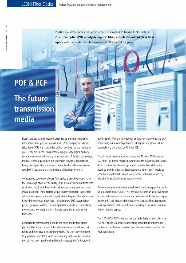
Plastics are attracting increasing attention as a means to transmit
information. Pure polymer optical fibers (POF) and polymer cladded
silica fibers (PCF) with step index profile have been on the market for
years. They have been used primarily in high-range digital audio sys-
tems, the automotive industry, some segments of lighting technology,
medical technology, and on bus systems in industrial applications.
Bus system applications are found primarily where there are signifi-
cant EMC issues and the transmission path is relatively short.
Compared to conventional glass fiber optics, plastic fiber optics have
the advantage of greater flexibility (high alternate bending stress with
small bend radii), and they are also a low-cost connection and trans-
mission solution. These factors are particularly important in mechani-
cal engineering and automation applications. Polymer fiber optics also
have all the essential properties – including low EMC susceptibility,
perfect galvanic isolation, low susceptibility to electronic surveillance,
no cross talk, low weight, etc. – that are generally associated with
fiber optics.
Compared to common single-mode and multi-mode fiber optics,
polymer fiber optics have a higher attenuation, which reduces their
range, and they have a smaller bandwidth. The latest developments
(e.g. gradient index POF), which are currently in the market introduc-
tion phase, show that there is still significant potential for improved
performance. With the introduction of Ethernet technology and LAN
networking in industrial applications, designers and planners have
been taking a closer look at POF and PCF.
The distances that can now be bridged are 70 m for POF fibers and
500 m for PCF fibers, regarded as sufficient for industrial applications.
If you consider that the average length from the floor distribution
board to a workstation in a local network is 45 m, then it would ap-
pear that using POF/PCF is not so unrealistic. Solutions are already
available for small office and home networks.
Once the necessary hardware is available in sufficient quantities and at
an affordable price, POF/PCF will certainly become an attractive option
in many office networks. Despite the drive towards higher and higher
bandwidths, 125 Mbit/sec Ethernet connections will be adequate for
most applications in the near future, especially if the user focuses on
the cost-benefit aspect.
The “LEONI iQ-LINE” offers you various cable designs using plastic or
PCF fiber optics to enhance our existing broad range of fiber optic
cables and to allow you to select the best transmission medium for
your application.
4
ww
w.le
oni-
fib
er-o
ptic
s.co
m
Plastics are attracting increasing attention as a means to transmit information.
Pure fiber optics (POF – polymer optical fiber) and plastic-coated glass fiber
optics with step index profile have been on the market for years.
POF & PCF
The future transmission media
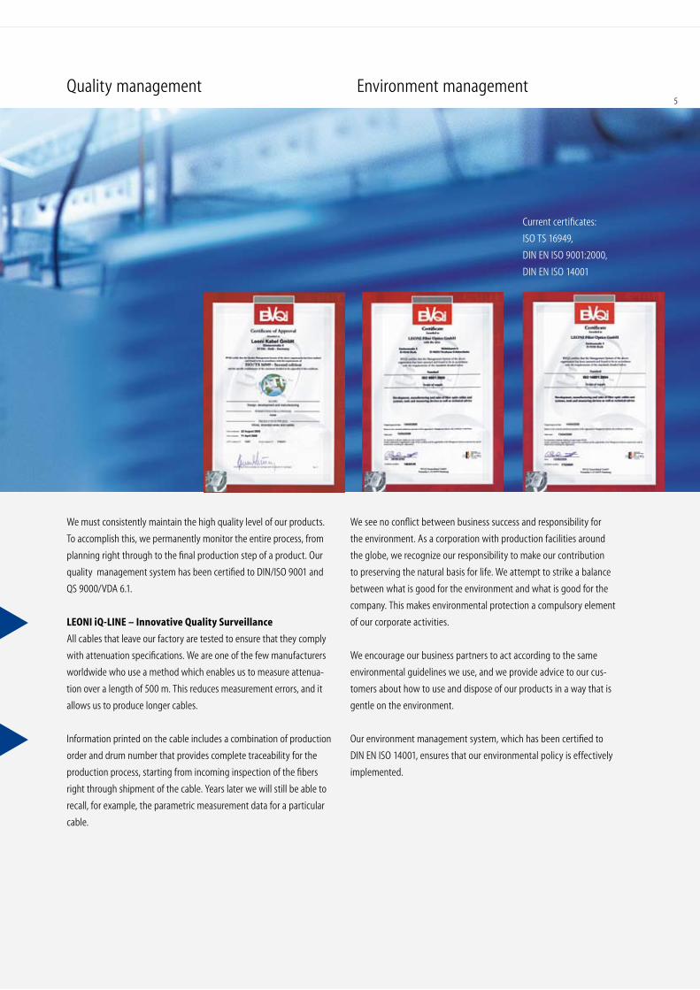
Current certificates:
ISO TS 16949,
DIN EN ISO 9001:2000,
DIN EN ISO 14001
We see no conflict between business success and responsibility for
the environment. As a corporation with production facilities around
the globe, we recognize our responsibility to make our contribution
to preserving the natural basis for life. We attempt to strike a balance
between what is good for the environment and what is good for the
company. This makes environmental protection a compulsory element
of our corporate activities.
We encourage our business partners to act according to the same
environmental guidelines we use, and we provide advice to our cus-
tomers about how to use and dispose of our products in a way that is
gentle on the environment.
Our environment management system, which has been certified to
DIN EN ISO 14001, ensures that our environmental policy is effectively
implemented.
We must consistently maintain the high quality level of our products.
To accomplish this, we permanently monitor the entire process, from
planning right through to the final production step of a product. Our
quality management system has been certified to DIN/ISO 9001 and
QS 9000/VDA 6.1.
LEONI iQ-LINE – Innovative Quality Surveillance
All cables that leave our factory are tested to ensure that they comply
with attenuation specifications. We are one of the few manufacturers
worldwide who use a method which enables us to measure attenua-
tion over a length of 500 m. This reduces measurement errors, and it
allows us to produce longer cables.
Information printed on the cable includes a combination of production
order and drum number that provides complete traceability for the
production process, starting from incoming inspection of the fibers
right through shipment of the cable. Years later we will still be able to
recall, for example, the parametric measurement data for a particular
cable.
Quality management Environment management5
LEONI Fiber Optics Jacketing material | Attenuation test
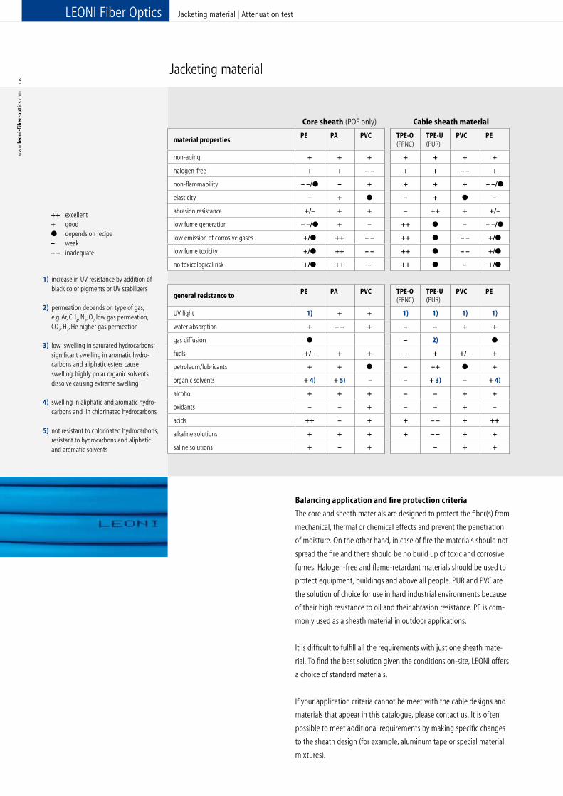
Jacketing material
1) increase in UV resistance by addition of black color pigments or UV stabilizers
2) permeation depends on type of gas, e.g. Ar, CH
4, N
2, O
2 low gas permeation,
CO2, H
2, He higher gas permeation
3) low swelling in saturated hydrocarbons; significant swelling in aromatic hydro-
carbons and aliphatic esters cause swelling, highly polar organic solvents dissolve causing extreme swelling
4) swelling in aliphatic and aromatic hydro- carbons and in chlorinated hydrocarbons
5) not resistant to chlorinated hydrocarbons, resistant to hydrocarbons and aliphatic and aromatic solvents
++ excellent+ good● depends on recipe– weak– – inadequate
Balancing application and fire protection criteria
The core and sheath materials are designed to protect the fiber(s) from
mechanical, thermal or chemical effects and prevent the penetration
of moisture. On the other hand, in case of fire the materials should not
spread the fire and there should be no build up of toxic and corrosive
fumes. Halogen-free and flame-retardant materials should be used to
protect equipment, buildings and above all people. PUR and PVC are
the solution of choice for use in hard industrial environments because
of their high resistance to oil and their abrasion resistance. PE is com-
monly used as a sheath material in outdoor applications.
It is difficult to fulfill all the requirements with just one sheath mate-
rial. To find the best solution given the conditions on-site, LEONI offers
a choice of standard materials.
If your application criteria cannot be meet with the cable designs and
materials that appear in this catalogue, please contact us. It is often
possible to meet additional requirements by making specific changes
to the sheath design (for example, aluminum tape or special material
mixtures).
6
ww
w.le
oni-
fib
er-o
ptic
s.co
m
Core sheath (POF only) Cable sheath material
material propertiesPE PA PVC TPE-O
(FRNC)TPE-U (PUR)
PVC PE
non-aging + + + + + + +
halogen-free + + – – + + – – +
non-flammability – –/● – + + + + – –/●
elasticity – + ● – + ● –
abrasion resistance +/– + + – ++ + +/–
low fume generation – –/● + – ++ ● – – –/●
low emission of corrosive gases +/● ++ – – ++ ● – – +/●
low fume toxicity +/● ++ – – ++ ● – – +/●
no toxicological risk +/● ++ – ++ ● – +/●
general resistance toPE PA PVC TPE-O
(FRNC)TPE-U (PUR)
PVC PE
UV light 1) + + 1) 1) 1) 1)
water absorption + – – + – – + +
gas diffusion ● – 2) ●
fuels +/– + + – + +/– +
petroleum/lubricants + + ● – ++ ● +
organic solvents + 4) + 5) – – + 3) – + 4)
alcohol + + + – – + +
oxidants – – + – – + –
acids ++ – + + – – + ++
alkaline solutions + + + + – – + +
saline solutions + – + – + +
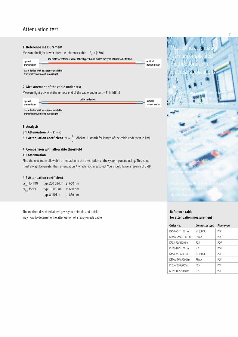
Attenuation test
1. Reference measurement
Measure the light power after the reference cable – PS in [dBm]
2. Measurement of the cable under test
Measure light power at the remote end of the cable under test – PL in [dBm]
3. Analysis
3.1 Attenuation A = PL – P
S
3.2 Attenuation coefficient α = — dB/km (L stands for length of the cable under test in km)
4. Comparison with allowable threshold
4.1 Attenuation
Find the maximum allowable attenuation in the description of the system you are using. This value
must always be greater than attenuation A which you measured. You should leave a reserve of 3 dB.
4.2 Attenuation coefficient
αmax
for POF typ. 230 dB/km at 660 nm
αmax
for PCF typ. 10 dB/km at 660 nm
typ. 8 dB/km at 850 nm
Reference cable
for attenuation measurement
AL
Tip
If you use PCF fiber optics in systems for POF,
in other words 660 nm and your system is not
explicitly specified for PCF fibers, proceed as
follows:
■ use a POF cable instead of a PCF cable
as a reference cable
■ attenuation:
A = PL (PCF cable) – P
S (POF reference)
In our analysis (4.1), the maximum
allowable attenuation must be greater
than the attenuation you have measured.
Experience shows that this method is one of
the most reliable, but you cannot determine
the attenuation coefficient (3.2) in this way.
It is better to use the transmitter that is built
into the system (and not the transmitter
described above).
see table for reference cable (fiber type should match the type of fiber to be tested)optical power meter
cable under test
Order No. Connector type Fiber type
KXST-XST 11001m ST (BFOC) POF
KSMA-SMA 11001m FSMA POF
KF05-F0511001m F05 POF
KHPS-HPS11001m HP POF
KXST-XST72001m ST (BFOC) PCF
KSMA-SMA72001m FSMA PCF
KF05-F0572001m F05 PCF
KHPS-HPS72001m HP PCF
opticaltransmitter
basic device with adapter or available transmitter with continuous light
optical transmitter
basic device with adapter or available transmitter with continuous light
optical power meter
The method described above gives you a simple and quick
way how to determine the attenuation of a ready-made cable.
Measuring attenuation – an uncomplicated method for use in practical applications
7
LEONI Fiber Optics Labelling code | Part number codes for odering
8
ww
w.le
oni-
fib
er-o
ptic
s.co
m
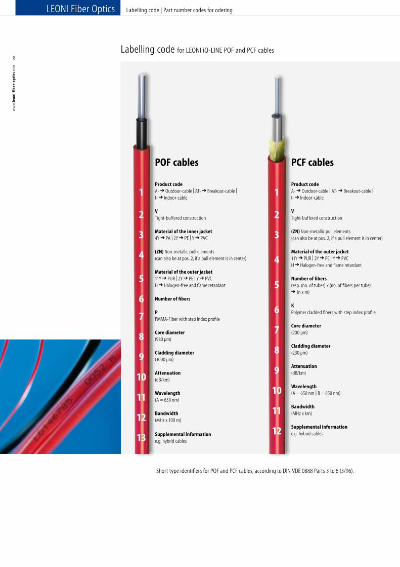
Labelling code for LEONI iQ-LINE POF and PCF cables
Short type identifiers for POF and PCF cables, according to DIN VDE 0888 Parts 3 to 6 (3/96).
POF cables Product code A- ➔ Outdoor-cable | AT- ➔ Breakout-cable |
I- ➔ Indoor-cable
V Tight-buffered construction
Material of the inner jacket 4Y ➔ PA | 2Y ➔ PE | Y ➔ PVC (ZN) Non-metallic pull elements (can also be at pos. 2, if a pull element is in center) Material of the outer jacket 11Y ➔ PUR | 2Y ➔ PE | Y ➔ PVCH ➔ Halogen-free and flame retardant
Number of fibers P PMMA-Fiber with step index profile Core diameter (980 µm) Cladding diameter (1000 µm) Attenuation (dB/km) Wavelength (A = 650 nm) Bandwidth (MHz x 100 m)
Supplemental information e.g. hybrid cables
PCF cables
Product code A- ➔ Outdoor-cable | AT- ➔ Breakout-cable |
I- ➔ Indoor-cable
V Tight-buffered construction (ZN) Non-metallic pull elements (can also be at pos. 2, if a pull element is in center)
Material of the outer jacket 11Y ➔ PUR | 2Y ➔ PE | Y ➔ PVCH ➔ Halogen-free and flame retardant
Number of fibers resp. (no. of tubes) x (no. of fibers per tube) ➔ (n x m) K Polymer cladded fibers with step index profile Core diameter (200 µm) Cladding diameter (230 µm) Attenuation (dB/km) Wavelength (A = 650 nm | B = 850 nm) Bandwidth (MHz x km)
Supplemental information e.g. hybrid cables
1
2
3
4
5
6
7
8
9
10
11
12
13
1
2
3
4
5
6
7
8
9
10
11
12
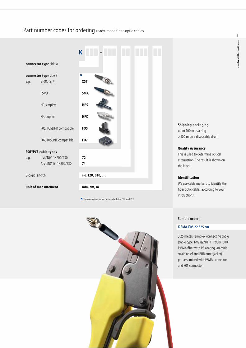
The connectors shown are available for POF and PCF
K –
connector type side A
connector type side B
e.g. BFOC (ST®) XST
FSMA SMA
HP, simplex HPS
HP, duplex HPD
F05, TOSLINK compatible FO5
F07, TOSLINK compatible FO7
POF/PCF cable types
e.g. I-V(ZN)Y 1K200/230 72
A-V(ZN)11Y 1K200/230 74
3-digit length e.g. 128, 010, …
unit of measurement mm, cm, m
Part number codes for ordering ready-made fiber-optic cables
Sample order:
K SMA-F05 22 325 cm
3.25 meters, simplex connecting cable
(cable type: I-V2Y(ZN)11Y 1P980/1000,
PMMA fiber with PE coating, aramide
strain relief and PUR outer jacket)
pre-assembled with FSMA connector
and F05 connector
Shipping packaging
up to 100 m as a ring
>100 m on a disposable drum
Quality Assurance
This is used to determine optical
attenuation. The result is shown on
the label.
Identification
We use cable markers to identify the
fiber optic cables according to your
instructions.
9
ww
w.le
oni-
fib
er-o
ptic
s.co
m
POF
V-2Y 1P980/1000
POF Cables
Cables
10
ww
w.le
oni-
fib
er-o
ptic
s.co
m
POF cables are available for both indoor and outdoor applications. We offer many dif-ferent designs to meet the large variety of applications in the industrial environment. Special requirements in terms of flexibility, resistance to oil, resistance to UV-light, halogen-free or flame-retardant properties are met by selecting suitable materials.
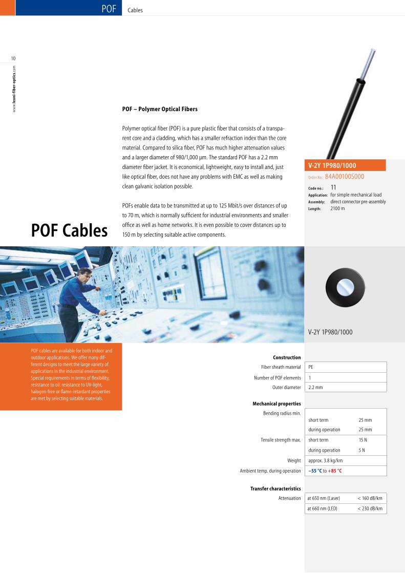
POF – Polymer Optical Fibers
Polymer optical fiber (POF) is a pure plastic fiber that consists of a transpa-
rent core and a cladding, which has a smaller refraction index than the core
material. Compared to silica fiber, POF has much higher attenuation values
and a larger diameter of 980/1,000 µm. The standard POF has a 2.2 mm
diameter fiber jacket. It is economical, lightweight, easy to install and, just
like optical fiber, does not have any problems with EMC as well as making
clean galvanic isolation possible.
POFs enable data to be transmitted at up to 125 Mbit/s over distances of up
to 70 m, which is normally sufficient for industrial environments and smaller
office as well as home networks. It is even possible to cover distances up to
150 m by selecting suitable active components.
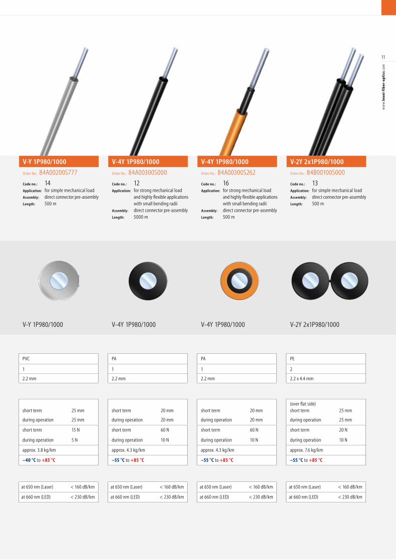
Construction
Fiber sheath material PE PVC PA PA PE
Number of POF elements 1 1 1 1 2
Outer diameter 2.2 mm 2.2 mm 2.2 mm 2.2 mm 2.2 x 4.4 mm
Mechanical properties
Bending radius min. short term 25 mm
short term 25 mm
short term 20 mm
short term 20 mm
(over flat side)short term 25 mm
during operation 25 mm during operation 25 mm during operation 20 mm during operation 20 mm during operation 25 mm
Tensile strength max. short term 15 N short term 15 N short term 60 N short term 60 N short term 20 N
during operation 5 N during operation 5 N during operation 10 N during operation 10 N during operation 10 N
Weight approx. 3.8 kg/km approx. 3.8 kg/km approx. 4.3 kg/km approx. 4.3 kg/km approx. 7.6 kg/km
Ambient temp. during operation –55 °C to +85 °C –40 °C to +85 °C –55 °C to +85 °C –55 °C to +85 °C –55 °C to +85 °C
Transfer characteristics
Attenuation at 650 nm (Laser) < 160 dB/km at 650 nm (Laser) < 160 dB/km at 650 nm (Laser) < 160 dB/km at 650 nm (Laser) < 160 dB/km at 650 nm (Laser) < 160 dB/km
at 660 nm (LED) < 230 dB/km at 660 nm (LED) < 230 dB/km at 660 nm (LED) < 230 dB/km at 660 nm (LED) < 230 dB/km at 660 nm (LED) < 230 dB/km
V-2Y 1P980/1000
Order No.: 84A00100S000
Code no.: 11Application: for simple mechanical load Assembly: direct connector pre-assemblyLength: 2100 m
11
ww
w.le
oni-
fib
er-o
ptic
s.co
m
V-Y 1P980/1000 V-4Y 1P980/1000 V-4Y 1P980/1000
Construction
Fiber sheath material PE PVC PA PA PE
Number of POF elements 1 1 1 1 2
Outer diameter 2.2 mm 2.2 mm 2.2 mm 2.2 mm 2.2 x 4.4 mm
Mechanical properties
Bending radius min. short term 25 mm
short term 25 mm
short term 20 mm
short term 20 mm
(over flat side)short term 25 mm
during operation 25 mm during operation 25 mm during operation 20 mm during operation 20 mm during operation 25 mm
Tensile strength max. short term 15 N short term 15 N short term 60 N short term 60 N short term 20 N
during operation 5 N during operation 5 N during operation 10 N during operation 10 N during operation 10 N
Weight approx. 3.8 kg/km approx. 3.8 kg/km approx. 4.3 kg/km approx. 4.3 kg/km approx. 7.6 kg/km
Ambient temp. during operation –55 °C to +85 °C –40 °C to +85 °C –55 °C to +85 °C –55 °C to +85 °C –55 °C to +85 °C
Transfer characteristics
Attenuation at 650 nm (Laser) < 160 dB/km at 650 nm (Laser) < 160 dB/km at 650 nm (Laser) < 160 dB/km at 650 nm (Laser) < 160 dB/km at 650 nm (Laser) < 160 dB/km
at 660 nm (LED) < 230 dB/km at 660 nm (LED) < 230 dB/km at 660 nm (LED) < 230 dB/km at 660 nm (LED) < 230 dB/km at 660 nm (LED) < 230 dB/km
V-2Y 2x1P980/1000
V-Y 1P980/1000
Order No.: 84A00200S777
Code no.: 14Application: for simple mechanical loadAssembly: direct connector pre-assembly Length: 500 m
V-4Y 1P980/1000
Order No.: 84A00300S000
Code no.: 12Application: for strong mechanical load and highly flexible applications with small bending radii Assembly: direct connector pre-assembly Length: 5000 m
V-4Y 1P980/1000
Order No.: 84A00300S262
Code no.: 16Application: for strong mechanical load and highly flexible applications with small bending radii Assembly: direct connector pre-assembly Length: 500 m
V-2Y 2x1P980/1000
Order No.: 84B00100S000
Code no.: 13Application: for simple mechanical loadAssembly: direct connector pre-assembly Length: 500 m
POF
POF Cables
Cables
12
ww
w.le
oni-
fib
er-o
ptic
s.co
m
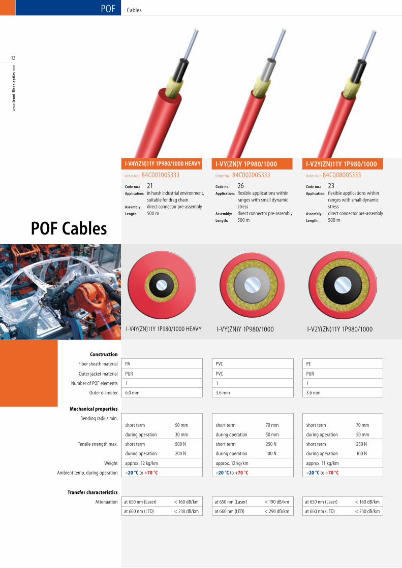
I-V2Y(ZN)11Y 1P980/1000
Construction
Fiber sheath material PA PVC PE PE PE PE
Outer jacket material PUR PVC PUR PUR FRNC FRNC
Number of POF elements 1 1 1 1 2 2
Outer diameter 6.0 mm 3.6 mm 3.6 mm 6.0 mm 4.7 x 8.2 mm 3.6 x 7.5 mm
Mechanical properties
Bending radius min. short term 50 mm short term 70 mm short term 70 mm short term 70 mm
(over flat side)short term 70 mm
(over flat side)short term 70 mm
during operation 30 mm during operation 50 mm during operation 50 mm during operation 50 mm during operation 50 mm during operation 50 mm
Tensile strength max. short term 500 N short term 250 N short term 250 N short term 400 N short term 400 N short term 400 N
during operation 200 N during operation 100 N during operation 100 N during operation 100 N during operation 100 N during operation 100 N
Weight approx. 32 kg/km approx. 12 kg/km approx. 11 kg/km approx. 32 kg/km approx. 43 kg/km approx. 28 kg/km
Ambient temp. during operation –20 °C to +70 °C –20 °C to +70 °C –20 °C to +70 °C –20 °C to +70 °C –20 °C to +70 °C –20 °C to +70 °C
Transfer characteristics
Attenuation at 650 nm (Laser) < 160 dB/km at 650 nm (Laser) < 190 dB/km at 650 nm (Laser) < 160 dB/km at 650 nm (Laser) < 160 dB/km at 650 nm (Laser) < 190 dB/km at 650 nm (Laser) < 190 dB/km
at 660 nm (LED) < 230 dB/km at 660 nm (LED) < 290 dB/km at 660 nm (LED) < 230 dB/km at 660 nm (LED) < 230 dB/km at 660 nm (LED) < 290 dB/km at 660 nm (LED) < 290 dB/km
I-VY(ZN)Y 1P980/1000I-V4Y(ZN)11Y 1P980/1000 HEAVY
I-VY(ZN)Y 1P980/1000
Order No.: 84C00200S333
Code no.: 26Application: flexible applications within ranges with small dynamic stressAssembly: direct connector pre-assembly Length: 500 m
I-V4Y(ZN)11Y 1P980/1000 HEAVY
Order No.: 84C00100S333
Code no.: 21Application: in harsh industrial environment, suitable for drag chain Assembly: direct connector pre-assembly Length: 500 m
I-V2Y(ZN)11Y 1P980/1000
Order No.: 84C00800S333
Code no.: 23Application: flexible applications within ranges with small dynamic stress
Assembly: direct connector pre-assembly Length: 500 m
13
ww
w.le
oni-
fib
er-o
ptic
s.co
m
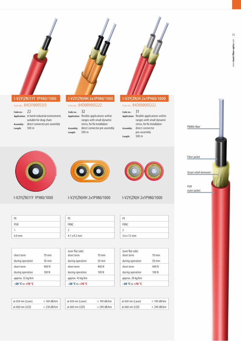
I-V2Y(ZN)11Y 1P980/1000 I-V2Y(ZN)HH 2x1P980/1000 I-V2Y(ZN)H 2x1P980/1000
Construction
Fiber sheath material PA PVC PE PE PE PE
Outer jacket material PUR PVC PUR PUR FRNC FRNC
Number of POF elements 1 1 1 1 2 2
Outer diameter 6.0 mm 3.6 mm 3.6 mm 6.0 mm 4.7 x 8.2 mm 3.6 x 7.5 mm
Mechanical properties
Bending radius min. short term 50 mm short term 70 mm short term 70 mm short term 70 mm
(over flat side)short term 70 mm
(over flat side)short term 70 mm
during operation 30 mm during operation 50 mm during operation 50 mm during operation 50 mm during operation 50 mm during operation 50 mm
Tensile strength max. short term 500 N short term 250 N short term 250 N short term 400 N short term 400 N short term 400 N
during operation 200 N during operation 100 N during operation 100 N during operation 100 N during operation 100 N during operation 100 N
Weight approx. 32 kg/km approx. 12 kg/km approx. 11 kg/km approx. 32 kg/km approx. 43 kg/km approx. 28 kg/km
Ambient temp. during operation –20 °C to +70 °C –20 °C to +70 °C –20 °C to +70 °C –20 °C to +70 °C –20 °C to +70 °C –20 °C to +70 °C
Transfer characteristics
Attenuation at 650 nm (Laser) < 160 dB/km at 650 nm (Laser) < 190 dB/km at 650 nm (Laser) < 160 dB/km at 650 nm (Laser) < 160 dB/km at 650 nm (Laser) < 190 dB/km at 650 nm (Laser) < 190 dB/km
at 660 nm (LED) < 230 dB/km at 660 nm (LED) < 290 dB/km at 660 nm (LED) < 230 dB/km at 660 nm (LED) < 230 dB/km at 660 nm (LED) < 290 dB/km at 660 nm (LED) < 290 dB/km
PURouter jacket
Strain relief elements
Fiber jacket
PMMA fiber
I-V2Y(ZN)11Y 1P980/1000
Order No.: 84C01000S333
Code no.: 22Application: in harsh industrial environment, suitable for drag chainAssembly: direct connector pre-assemblyLength: 500 m
I-V2Y(ZN)HH 2x1P980/1000
Order No.: 84D00900S222
Code no.: 32Application: flexible applications within ranges with small dynamic stress, for fix installation Assembly: direct connector pre-assemblyLength: 500 m
I-V2Y(ZN)H 2x1P980/1000
Order No.: 84D03000S222
Code no.: 31Application: flexible applications within ranges with small dynamic stress, for fix installationAssembly: direct connector pre-assembly Length: 500 m
14
ww
w.le
oni-
fib
er-o
ptic
s.co
m
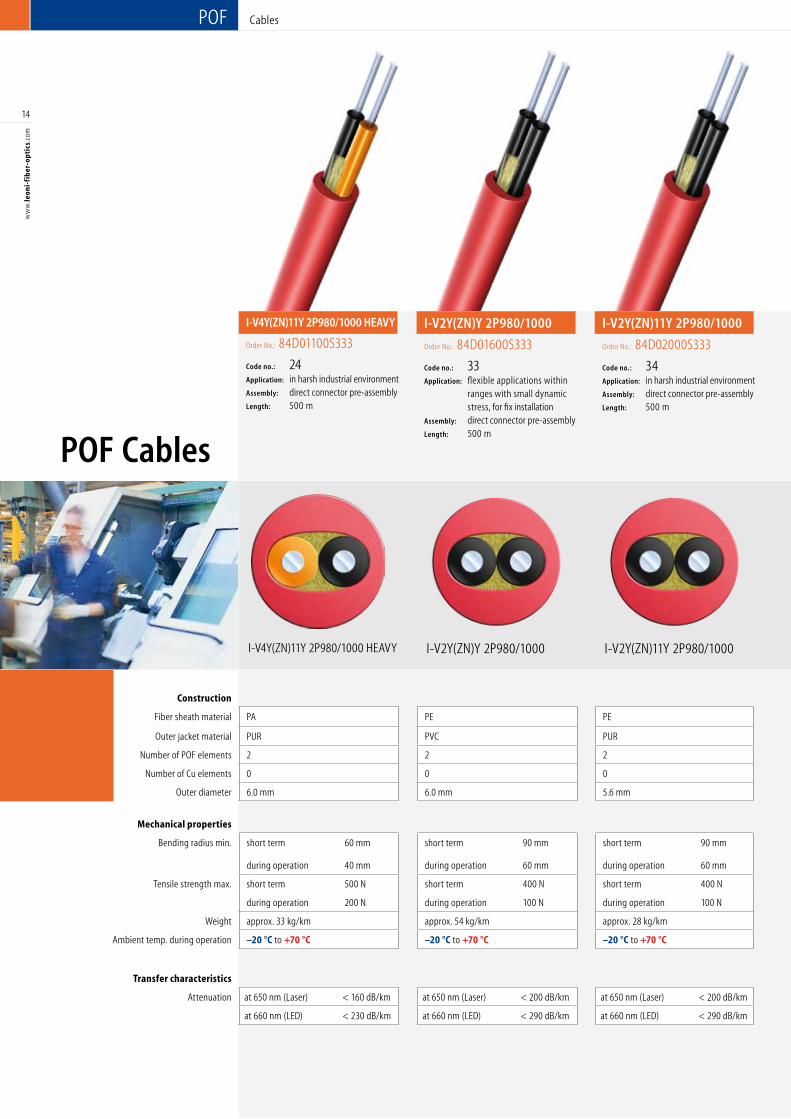
I-V2Y(ZN)11Y 2P980/1000
Construction
Fiber sheath material PA PE PE PE PA PE
Outer jacket material PUR PVC PUR PUR PUR PUR
Number of POF elements 2 2 2 2 2 2
Number of Cu elements 0 0 0 0 0 2
Outer diameter 6.0 mm 6.0 mm 5.6 mm 6.4 mm 8.0 mm 7.5 mm
Mechanical properties
Bending radius min. short term 60 mm short term 90 mm short term 90 mm short term 90 mm short term 60 mm short term 90 mm
during operation 40 mm during operation 60 mm during operation 60 mm during operation 60 mm during operation 40 mm during operation 60 mm
Tensile strength max. short term 500 N short term 400 N short term 400 N short term 200 N short term 400 N short term 200 N
during operation 200 N during operation 100 N during operation 100 N during operation 100 N during operation 100 N during operation 100 N
Weight approx. 33 kg/km approx. 54 kg/km approx. 28 kg/km approx. 30 kg/km approx. 55 kg/km approx. 62 kg/km
Ambient temp. during operation –20 °C to +70 °C –20 °C to +70 °C –20 °C to +70 °C –20 °C to +70 °C –20 °C to +70 °C –20 °C to +70 °C
Transfer characteristics
Attenuation at 650 nm (Laser) < 160 dB/km at 650 nm (Laser) < 200 dB/km at 650 nm (Laser) < 200 dB/km at 650 nm (Laser) < 220 dB/km at 650 nm (Laser) < 190 dB/km at 650 nm (Laser) < 220 dB/km
at 660 nm (LED) < 230 dB/km at 660 nm (LED) < 290 dB/km at 660 nm (LED) < 290 dB/km at 660 nm (LED) < 350 dB/km at 660 nm (LED) < 290 dB/km at 660 nm (LED) < 350 dB/km
I-V2Y(ZN)Y 2P980/1000I-V4Y(ZN)11Y 2P980/1000 HEAVY
POF
POF Cables
Cables
I-V2Y(ZN)Y 2P980/1000
Order No.: 84D01600S333
Code no.: 33Application: flexible applications within ranges with small dynamic stress, for fix installationAssembly: direct connector pre-assemblyLength: 500 m
I-V4Y(ZN)11Y 2P980/1000 HEAVY
Order No.: 84D01100S333
Code no.: 24Application: in harsh industrial environment Assembly: direct connector pre-assemblyLength: 500 m
I-V2Y(ZN)11Y 2P980/1000
Order No.: 84D02000S333
Code no.: 34Application: in harsh industrial environment Assembly: direct connector pre-assemblyLength: 500 m
15
ww
w.le
oni-
fib
er-o
ptic
s.co
m
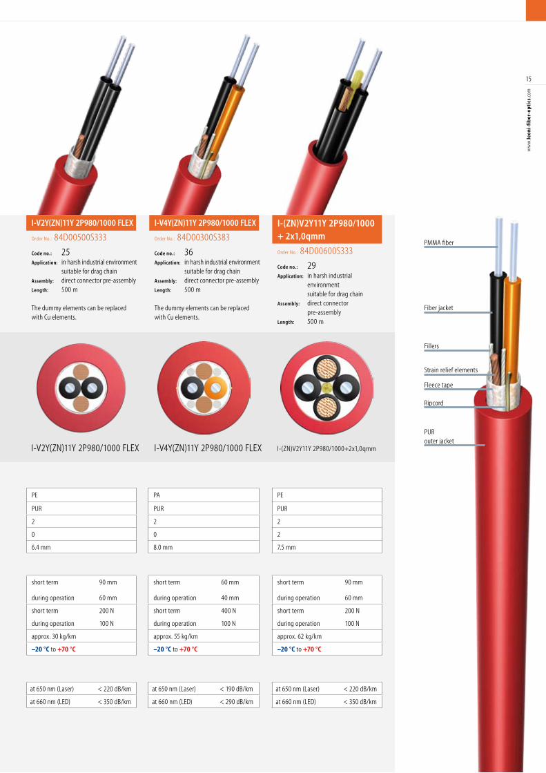
I-V2Y(ZN)11Y 2P980/1000 FLEX I-V4Y(ZN)11Y 2P980/1000 FLEX I-(ZN)V2Y11Y 2P980/1000+2x1,0qmm
Construction
Fiber sheath material PA PE PE PE PA PE
Outer jacket material PUR PVC PUR PUR PUR PUR
Number of POF elements 2 2 2 2 2 2
Number of Cu elements 0 0 0 0 0 2
Outer diameter 6.0 mm 6.0 mm 5.6 mm 6.4 mm 8.0 mm 7.5 mm
Mechanical properties
Bending radius min. short term 60 mm short term 90 mm short term 90 mm short term 90 mm short term 60 mm short term 90 mm
during operation 40 mm during operation 60 mm during operation 60 mm during operation 60 mm during operation 40 mm during operation 60 mm
Tensile strength max. short term 500 N short term 400 N short term 400 N short term 200 N short term 400 N short term 200 N
during operation 200 N during operation 100 N during operation 100 N during operation 100 N during operation 100 N during operation 100 N
Weight approx. 33 kg/km approx. 54 kg/km approx. 28 kg/km approx. 30 kg/km approx. 55 kg/km approx. 62 kg/km
Ambient temp. during operation –20 °C to +70 °C –20 °C to +70 °C –20 °C to +70 °C –20 °C to +70 °C –20 °C to +70 °C –20 °C to +70 °C
Transfer characteristics
Attenuation at 650 nm (Laser) < 160 dB/km at 650 nm (Laser) < 200 dB/km at 650 nm (Laser) < 200 dB/km at 650 nm (Laser) < 220 dB/km at 650 nm (Laser) < 190 dB/km at 650 nm (Laser) < 220 dB/km
at 660 nm (LED) < 230 dB/km at 660 nm (LED) < 290 dB/km at 660 nm (LED) < 290 dB/km at 660 nm (LED) < 350 dB/km at 660 nm (LED) < 290 dB/km at 660 nm (LED) < 350 dB/km
PURouter jacket
Fleece tape
Ripcord
Fillers
PMMA fiber
Fiber jacket
Strain relief elements
I-V2Y(ZN)11Y 2P980/1000 FLEX
Order No.: 84D00500S333
Code no.: 25Application: in harsh industrial environment suitable for drag chain Assembly: direct connector pre-assembly Length: 500 m
The dummy elements can be replaced with Cu elements.
I-V4Y(ZN)11Y 2P980/1000 FLEX
Order No.: 84D00300S383
Code no.: 36Application: in harsh industrial environment suitable for drag chain Assembly: direct connector pre-assembly Length: 500 m
The dummy elements can be replaced with Cu elements.
I-(ZN)V2Y11Y 2P980/1000+ 2x1,0qmm
Order No.: 84D00600S333
Code no.: 29Application: in harsh industrial environment suitable for drag chainAssembly: direct connector pre-assemblyLength: 500 m
16
ww
w.le
oni-
fib
er-o
ptic
s.co
m
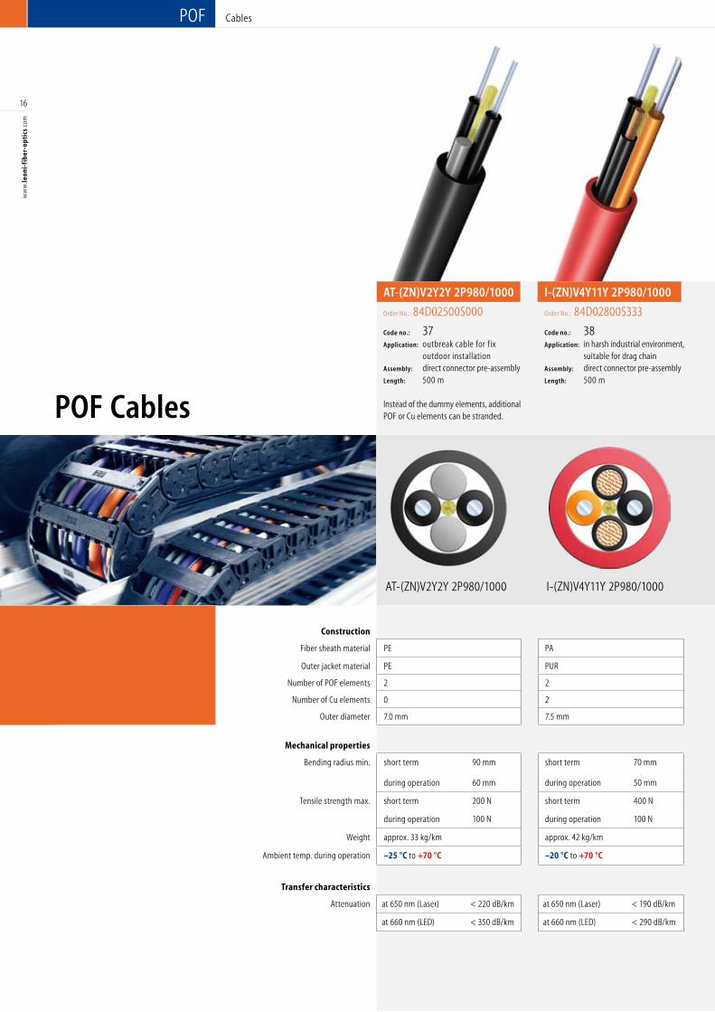
I-(ZN)V4Y11Y 2P980/1000AT-(ZN)V2Y2Y 2P980/1000
POF
Construction
Fiber sheath material PE PA PA PA PA
Outer jacket material PE PUR PUR PUR PVC
Number of POF elements 2 2 4 2 2
Number of Cu elements 0 2 0 4 3
Outer diameter 7.0 mm 7.5 mm 7.5 mm 10.6 mm 10.7 mm
Mechanical properties
Bending radius min. short term 90 mm short term 70 mm short term 70 mm short term 110 mm short term 110 mm
during operation 60 mm during operation 50 mm during operation 50 mm during operation 70 mm during operation 70 mm
Tensile strength max. short term 200 N short term 400 N short term 500 N short term 400 N short term 200 N
during operation 100 N during operation 100 N during operation 200 N during operation 100 N during operation 100 N
Weight approx. 33 kg/km approx. 42 kg/km approx. 42 kg/km approx. 146 kg/km approx. 132 kg/km
Ambient temp. during operation –25 °C to +70 °C –20 °C to +70 °C –20 °C to +70 °C –20 °C to +70 °C –20 °C to +70 °C
Transfer characteristics
Attenuation at 650 nm (Laser) < 220 dB/km at 650 nm (Laser) < 190 dB/km at 650 nm (Laser) < 190 dB/km at 650 nm (Laser) < 230 dB/km at 650 nm (Laser) < 230 dB/km
at 660 nm (LED) < 350 dB/km at 660 nm (LED) < 290 dB/km at 660 nm (LED) < 290 dB/km at 660 nm (LED) < 330 dB/km at 660 nm (LED) < 330 dB/km
POF Cables
Cables
AT-(ZN)V2Y2Y 2P980/1000
Order No.: 84D02500S000
Code no.: 37Application: outbreak cable for fix outdoor installation Assembly: direct connector pre-assembly Length: 500 m
Instead of the dummy elements, additional POF or Cu elements can be stranded.
I-(ZN)V4Y11Y 2P980/1000
Order No.: 84D02800S333
Code no.: 38Application: in harsh industrial environment, suitable for drag chainAssembly: direct connector pre-assembly Length: 500 m
17
ww
w.le
oni-
fib
er-o
ptic
s.co
m
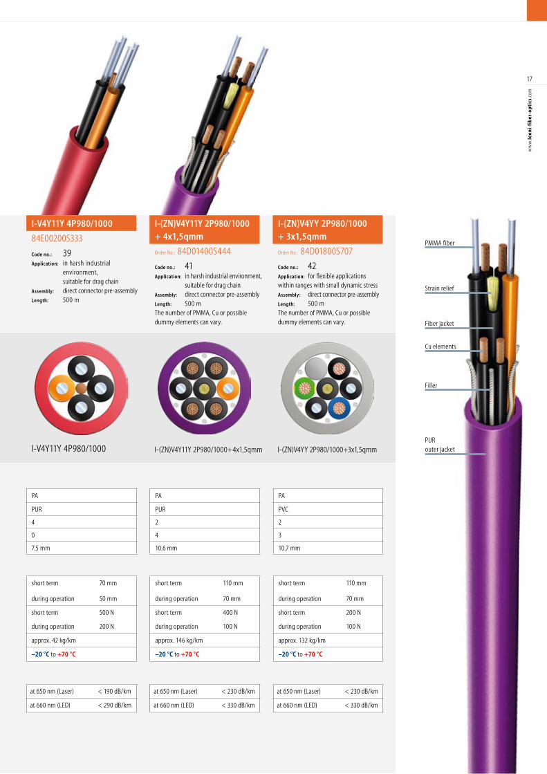
I-V4Y11Y 4P980/1000 I-(ZN)V4Y11Y 2P980/1000+4x1,5qmmPURouter jacket
Filler
Cu elements
PMMA fiber
Fiber jacket
Construction
Fiber sheath material PE PA PA PA PA
Outer jacket material PE PUR PUR PUR PVC
Number of POF elements 2 2 4 2 2
Number of Cu elements 0 2 0 4 3
Outer diameter 7.0 mm 7.5 mm 7.5 mm 10.6 mm 10.7 mm
Mechanical properties
Bending radius min. short term 90 mm short term 70 mm short term 70 mm short term 110 mm short term 110 mm
during operation 60 mm during operation 50 mm during operation 50 mm during operation 70 mm during operation 70 mm
Tensile strength max. short term 200 N short term 400 N short term 500 N short term 400 N short term 200 N
during operation 100 N during operation 100 N during operation 200 N during operation 100 N during operation 100 N
Weight approx. 33 kg/km approx. 42 kg/km approx. 42 kg/km approx. 146 kg/km approx. 132 kg/km
Ambient temp. during operation –25 °C to +70 °C –20 °C to +70 °C –20 °C to +70 °C –20 °C to +70 °C –20 °C to +70 °C
Transfer characteristics
Attenuation at 650 nm (Laser) < 220 dB/km at 650 nm (Laser) < 190 dB/km at 650 nm (Laser) < 190 dB/km at 650 nm (Laser) < 230 dB/km at 650 nm (Laser) < 230 dB/km
at 660 nm (LED) < 350 dB/km at 660 nm (LED) < 290 dB/km at 660 nm (LED) < 290 dB/km at 660 nm (LED) < 330 dB/km at 660 nm (LED) < 330 dB/km
I-(ZN)V4YY 2P980/1000+3x1,5qmm
Strain relief
I-V4Y11Y 4P980/1000Order No.:
84E00200S333
Code no.: 39Application: in harsh industrial environment, suitable for drag chainAssembly: direct connector pre-assembly Length: 500 m
I-(ZN)V4Y11Y 2P980/1000 + 4x1,5qmm
Order No.: 84D01400S444
Code no.: 41Application: in harsh industrial environment, suitable for drag chainAssembly: direct connector pre-assemblyLength: 500 m The number of PMMA, Cu or possible dummy elements can vary.
I-(ZN)V4YY 2P980/1000+ 3x1,5qmm
Order No.: 84D01800S707
Code no.: 42Application: for flexible applicationswithin ranges with small dynamic stressAssembly: direct connector pre-assemblyLength: 500 m The number of PMMA, Cu or possible dummy elements can vary.
POF Fiber Specifications
500
400
300
200
100
450 500 550 600 650
Atte
nuat
ion
[dB/
km]
Wavelength [nm]
Tran
smis
sion
/m [%
]
95
90
Typical values
18
ww
w.le
oni-
fib
er-o
ptic
s.co
m
POF Fiber Specifications
Description P980/1000 P240/250 P486/500 P735/750 P1470/1500 P1960/2000 P980/1000 low NA P980/1000 high NA P980/1000 high temperature POF
P980/1000 high temperature POF P485/500 high temperature POF
Description IEC 60793-2 A4a A4c A4b
Geometric/thermal properties
Core diameter 980 ± 60 µm 240 ± 23 µm 486 ± 30 µm 735 ± 45 µm 1470 ± 90 µm 1960 ± 120 µm 980 ± 60 µm 980 ± 60 µm 980 ± 60 µm 980 ± 60 µm 485 ± 30 µm
Cladding diameter 1000 ± 60 µm 250 ± 23 µm 500 ± 30 µm 750 ± 45 µm 1500 ± 90 µm 2000 ± 120 µm 1000 ± 60 µm 1000 ± 60 µm 1000 ± 60 µm 1000 ± 60 µm 500 ± 30 µm
Working temperature –55 °C to +85 °C –55 °C to +70 °C –55 °C to +70 °C –55 °C to +70 °C –55 °C to +70 °C –55 °C to +70 °C –40 °C to +70 °C –40 °C to +85 °C –55 °C to +105 °C –55 °C to +105 °C –55 °C to +105 °C
Transmission properties
Wavelength 650 nm 650 nm 650 nm 650 nm 650 nm 650 nm 650 nm 650 nm 650 nm 650 nm 650 nm
Attenuation max. 160 dB/km 300 dB/km 200 dB/km 180 dB/km 180 dB/km 180 dB/km 160 dB/km 160 dB/km 200 dB/km 200 dB/km 200 dB/km
Min. bandwidth (MHz x 100 m) 10 150
Numerical aperture 0.5 0.5 0.5 0.5 0.5 0.5 0.25 0.6 0.58 0.58 0.58
PMMA core
polymer cladding
Standard POF
Fiber TypeStandard
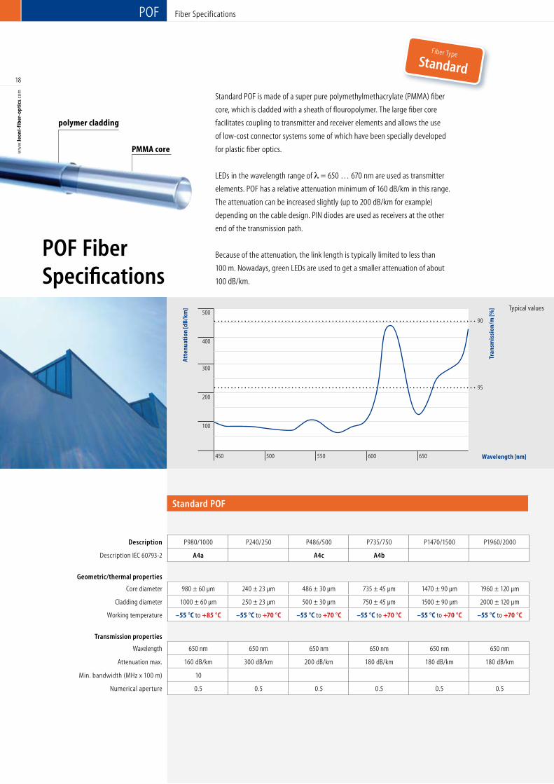
Standard POF is made of a super pure polymethylmethacrylate (PMMA) fiber
core, which is cladded with a sheath of flouropolymer. The large fiber core
facilitates coupling to transmitter and receiver elements and allows the use
of low-cost connector systems some of which have been specially developed
for plastic fiber optics.
LEDs in the wavelength range of = 650 … 670 nm are used as transmitter
elements. POF has a relative attenuation minimum of 160 dB/km in this range.
The attenuation can be increased slightly (up to 200 dB/km for example)
depending on the cable design. PIN diodes are used as receivers at the other
end of the transmission path.
Because of the attenuation, the link length is typically limited to less than
100 m. Nowadays, green LEDs are used to get a smaller attenuation of about
100 dB/km.
Wavelength [nm]
500
400
300
200
100
450 500 550 600 650
Atte
nuat
ion
[dB/
km]
Wavelength [nm]
Tran
smis
sion
/m [%
]
95
90
Typical values
19
ww
w.le
oni-
fib
er-o
ptic
s.co
mDescription P980/1000 P240/250 P486/500 P735/750 P1470/1500 P1960/2000 P980/1000 low NA P980/1000 high NA P980/1000
high temperature POF
P980/1000 high temperature POF P485/500 high temperature POF
Description IEC 60793-2 A4a A4c A4b
Geometric/thermal properties
Core diameter 980 ± 60 µm 240 ± 23 µm 486 ± 30 µm 735 ± 45 µm 1470 ± 90 µm 1960 ± 120 µm 980 ± 60 µm 980 ± 60 µm 980 ± 60 µm 980 ± 60 µm 485 ± 30 µm
Cladding diameter 1000 ± 60 µm 250 ± 23 µm 500 ± 30 µm 750 ± 45 µm 1500 ± 90 µm 2000 ± 120 µm 1000 ± 60 µm 1000 ± 60 µm 1000 ± 60 µm 1000 ± 60 µm 500 ± 30 µm
Working temperature –55 °C to +85 °C –55 °C to +70 °C –55 °C to +70 °C –55 °C to +70 °C –55 °C to +70 °C –55 °C to +70 °C –40 °C to +70 °C –40 °C to +85 °C –55 °C to +105 °C –55 °C to +105 °C –55 °C to +105 °C
Transmission properties
Wavelength 650 nm 650 nm 650 nm 650 nm 650 nm 650 nm 650 nm 650 nm 650 nm 650 nm 650 nm
Attenuation max. 160 dB/km 300 dB/km 200 dB/km 180 dB/km 180 dB/km 180 dB/km 160 dB/km 160 dB/km 200 dB/km 200 dB/km 200 dB/km
Min. bandwidth (MHz x 100 m) 10 150
Numerical aperture 0.5 0.5 0.5 0.5 0.5 0.5 0.25 0.6 0.58 0.58 0.58
Low NA/high NA POF High temperature-POF
Fiber Type
Special
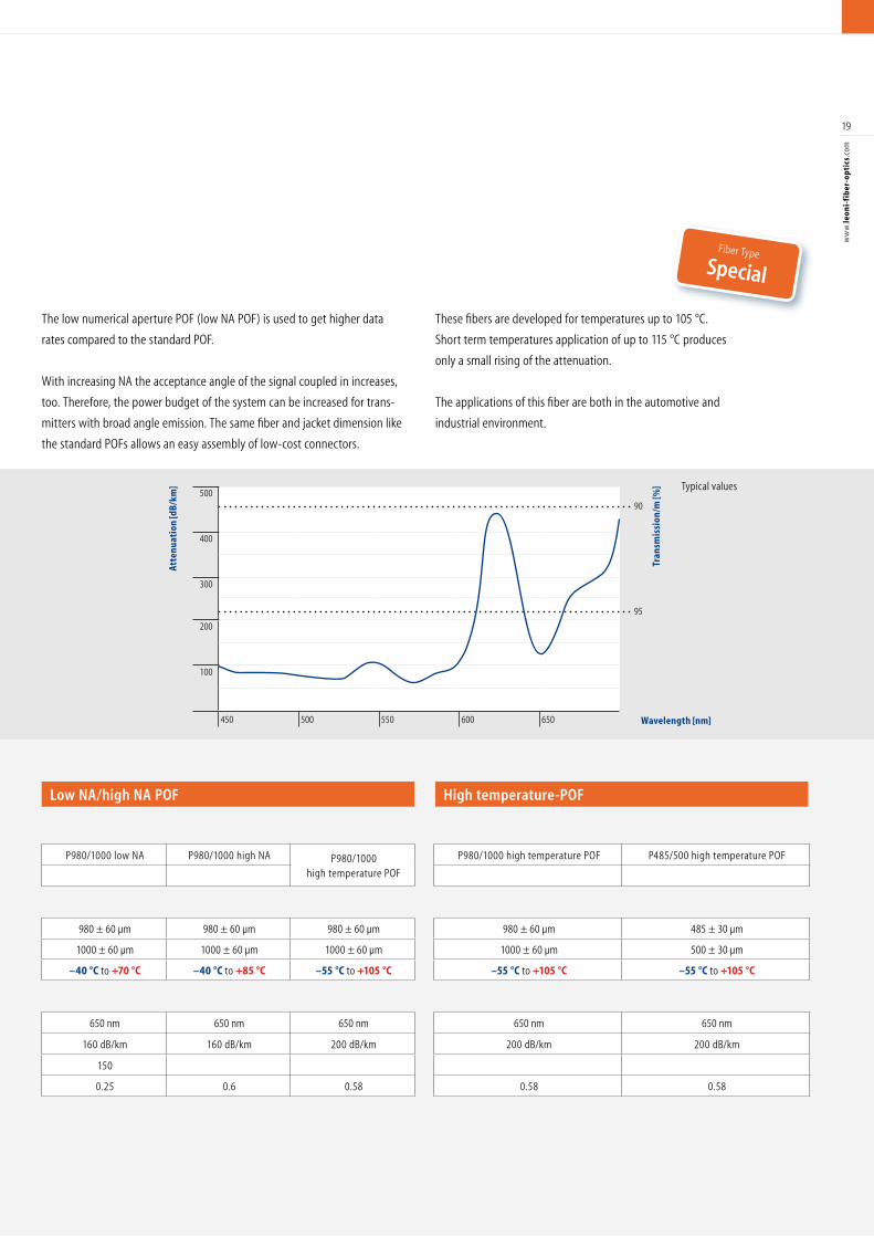
The low numerical aperture POF (low NA POF) is used to get higher data
rates compared to the standard POF.
With increasing NA the acceptance angle of the signal coupled in increases,
too. Therefore, the power budget of the system can be increased for trans-
mitters with broad angle emission. The same fiber and jacket dimension like
the standard POFs allows an easy assembly of low-cost connectors.
These fibers are developed for temperatures up to 105 °C.
Short term temperatures application of up to 115 °C produces
only a small rising of the attenuation.
The applications of this fiber are both in the automotive and
industrial environment.
20
ww
w.le
oni-
fib
er-o
ptic
s.co
m
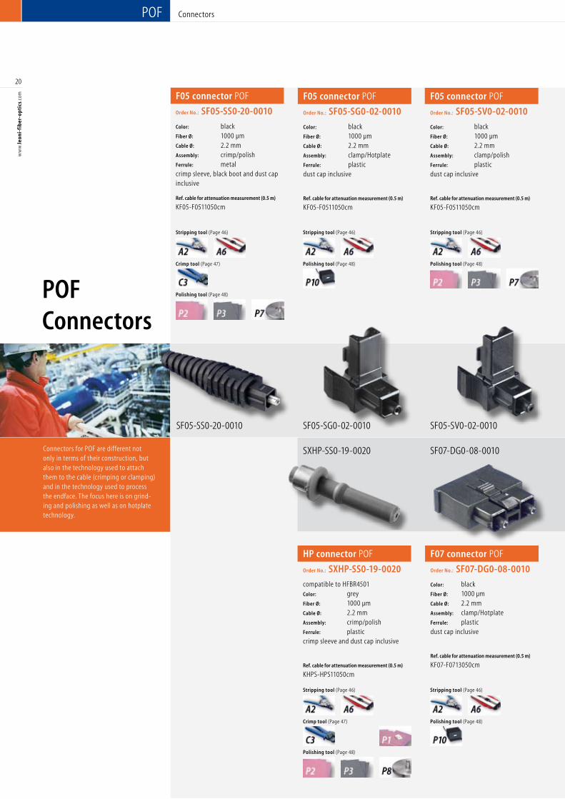
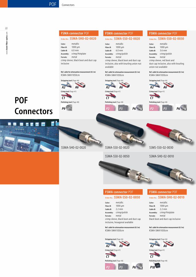
Connectors for POF are different not only in terms of their construction, but also in the technology used to attach them to the cable (crimping or clamping) and in the technology used to process the endface. The focus here is on grind-ing and polishing as well as on hotplate technology.
POF
F05 connector POF
Order No.: SF05-SS0-20-0010
Color: blackFiber Ø: 1000 µm Cable Ø: 2.2 mm Assembly: crimp/polish Ferrule: metalcrimp sleeve, black boot and dust cap inclusive
Ref. cable for attenuation measurement (0.5 m)
KF05-F0511050cm
SF05-SS0-20-0010
F05 connector POF
Order No.: SF05-SG0-02-0010
Color: blackFiber Ø: 1000 µm Cable Ø: 2.2 mm Assembly: clamp/Hotplate Ferrule: plasticdust cap inclusive
Ref. cable for attenuation measurement (0.5 m)
KF05-F0511050cm
F05 connector POF
Order No.: SF05-SV0-02-0010
Color: blackFiber Ø: 1000 µm Cable Ø: 2.2 mm Assembly: clamp/polish Ferrule: plasticdust cap inclusive
Ref. cable for attenuation measurement (0.5 m)
KF05-F0511050cm
F07 connector POF
Order No.: SF07-DG0-08-0010
Color: blackFiber Ø: 1000 µm Cable Ø: 2.2 mm Assembly: clamp/Hotplate Ferrule: plasticdust cap inclusive
Ref. cable for attenuation measurement (0.5 m)
KF07-F0713050cm
SF05-SG0-02-0010 SF05-SV0-02-0010
SF07-DG0-08-0010SXHP-SS0-19-0020
HP connector POF
Order No.: SXHP-SS0-19-0020
compatible to HFBR4501Color: grey Fiber Ø: 1000 µm Cable Ø: 2.2 mm Assembly: crimp/polish Ferrule: plasticcrimp sleeve and dust cap inclusive
Ref. cable for attenuation measurement (0.5 m)
KHPS-HPS11050cm
Stripping tool (Page 46)
Crimp tool (Page 47)
Polishing tool (Page 48)
Stripping tool (Page 46)
Polishing tool (Page 48)
Stripping tool (Page 46)
Polishing tool (Page 48)
Stripping tool (Page 46)
Crimp tool (Page 47)
Polishing tool (Page 48)
Stripping tool (Page 46)
Polishing tool (Page 48)
POF Connectors
Connectors
21
ww
w.le
oni-
fib
er-o
ptic
s.co
m
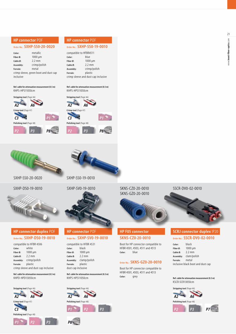
SKNS-CZ0-20-0010SKNS-GZ0-20-0010
HP F05 connectorOrder No.:
SKNS-CZ0-20-0010
Boot for HP connector compatible to HFBR 4501, 4503, 4511 and 4513Color: blue
Order No.: SKNS-GZ0-20-0010
Boot for HP connector compatible to HFBR 4501, 4503, 4511 and 4513Color: grey
SSCR-DV0-02-0010
SCRJ connector duplex IP20
Order No.: SSCR-DV0-02-0010
Color: black Fiber Ø: 1000 µm Cable Ø: 2.2 mm Assembly: clam/polish Ferrule: metalinclusive black boot and dust cap
Ref. cable for attenuation measurement (0.5 m)
KSCR-SCR13050cm
Stripping tool (Page 46)
Polishing tool (Page 48)
HP connector duplex POF
Order No.: SXHP-DS0-19-0010
compatible to HFBR 4506Color: white Fiber Ø: 1000 µm Cable Ø: 2.2 mm Assembly: crimp/polish Ferrule: plasticcrimp sleeve and dust cap inclusive
Ref. cable for attenuation measurement (0.5 m)
KHPD-HPD13050cm
SXHP-DS0-19-0010
SXHP-SS0-20-0020
SXHP-SV0-19-0010
SXHP-SS0-19-0010
HP connector POF
Order No.: SXHP-SS0-20-0020
Color: metallic Fiber Ø: 1000 µm Cable Ø: 2.2 mm Assembly: crimp/polish Ferrule: metalcrimp sleeve, green boot and dust cap inclusive
Ref. cable for attenuation measurement (0.5 m)
KHPS-HPS11050cm
HP connector POF
Order No.: SXHP-SS0-19-0010
compatible to HFBR4511Color: blue Fiber Ø: 1000 µm Cable Ø: 2.2 mm Assembly: crimp/polish Ferrule: plasticcrimp sleeve and dust cap inclusive
Ref. cable for attenuation measurement (0.5 m)
KHPS-HPS11050cm
HP connector POF
Order No.: SXHP-SV0-19-0010
compatible to HFBR 4531Color: black Fiber Ø: 1000 µm Cable Ø: 2.2 mm Assembly: clamp/polish Ferrule: plasticdust cap inclusive
Ref. cable for attenuation measurement (0.5 m)
KHPS-HPS11050cm
Stripping tool (Page 46)
Crimp tool (Page 47)
Polishing tool (Page 48)
Stripping tool (Page 46)
Crimp tool (Page 47)
Polishing tool (Page 48)
Stripping tool (Page 46)
Polishing tool (Page 48)
Stripping tool (Page 46)
Crimp tool (Page 47)
Polishing tool (Page 48)
22
ww
w.le
oni-
fib
er-o
ptic
s.co
m
SSMA-SH0-02-0010
FSMA connector POF
Order No.: SSMA-SH0-02-0010
Color: metallic Fiber Ø: 1000 µm Cable Ø: 2.2 mm Assembly: crimp/Hotplate Ferrule: metalblack boot and dust cap inclusive
Ref. cable for attenuation measurement (0.5 m)
KSMA-SMA11050cm
Stripping tool (Page 46)
Crimp tool (Page 47)
Polishing tool (Page 48)
POF
FSMA connector POF
Order No.: SSMA-SH0-02-0020
Color: metallic Fiber Ø: 1000 µm Cable Ø: 6.0 mm Assembly: crimp/Hotplate Ferrule: metalcrimp sleeve, black boot and dust cap inclusive
Ref. cable for attenuation measurement (0.5 m)
KSMA-SMA11050cm
SSMA-SH0-02-0020
FSMA connector POF
Order No.: SSMA-SS0-02-0020
Color: metallic Fiber Ø: 1000 µm Cable Ø: 6.0 mm Assembly: crimp/polish Ferrule: metalcrimp sleeve, black boot and dust cap inclusive, also with knurling union nut available
Ref. cable for attenuation measurement (0.5 m)
KSMA-SMA11050cm
FSMA connector POF
Order No.: SSMA-SS0-02-0030
Color: metallic Fiber Ø: 1000 µm Cable Ø: 3.6 mm Assembly: crimp/polish Ferrule: metalcrimp sleeve, red boot and dust cap inclusive, also with knurling union nut available
Ref. cable for attenuation measurement (0.5 m)
KSMA-SMA11050cm
FSMA connector POF
Order No.: SSMA-SS0-02-0050
Color: metallic Fiber Ø: 1000 µm Cable Ø: 2.2 mm Assembly: crimp/polish Ferrule: metalcrimp sleeve, black boot and dust cap inclusive, hexagonal available
Ref. cable for attenuation measurement (0.5 m)
KSMA-SMA11050cm
SSMA-SS0-02-0020 SSMS-SS0-02-0030
SSMA-SS0-02-0050
Stripping tool (Page 46)
Crimp tool (Page 47)
Polishing tool (Page 48)
Stripping tool (Page 46)
Crimp tool (Page 47)
Stripping tool (Page 46)
Stripping tool (Page 46)
Polishing tool (Page 48)
Crimp tool (Page 47)
Polishing tool (Page 48)
Crimp tool (Page 47)
Polishing tool (Page 48)
POF Connectors
Connectors
23
ww
w.le
oni-
fib
er-o
ptic
s.co
m
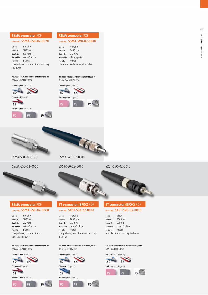
FSMA connector POF
Order No.: SSMA-SS0-02-0060
Color: metallic Fiber Ø: 1000 µm Cable Ø: 2.2 mm Assembly: crimp/polish Ferrule: plasticcrimp sleeve, black boot and dust cap inclusive
Ref. cable for attenuation measurement (0.5 m)
KSMA-SMA11050cm
SSMA-SS0-02-0060
SSMA-SS0-02-0070 SSMA-SV0-02-0010
SXST-SS0-22-0010 SXST-SV0-02-0010
FSMA connector POF
Order No.: SSMA-SS0-02-0070
Color: metallic Fiber Ø: 1000 µm Cable Ø: 6.0 mm Assembly: crimp/polish Ferrule: plastic crimp sleeve, black boot and dust cap inclusive
Ref. cable for attenuation measurement (0.5 m)
KSMA-SMA11050cm
FSMA connector POF
Order No.: SSMA-SV0-02-0010
Color: metallic Fiber Ø: 1000 µm Cable Ø: 2.2 mm Assembly: clamp/polish Ferrule: metalblack boot and dust cap inclusive
Ref. cable for attenuation measurement (0.5 m)
KSMA-SMA11050cm
ST connector (BFOC) POF
Order No.: SXST-SS0-22-0010
Color: metallic Fiber Ø: 1000 µm Cable Ø: 2.2 mm Assembly: crimp/polish Ferrule: metalcrimp sleeve, black boot and dust cap inclusive
Ref. cable for attenuation measurement (0.5 m)
KXST-XST11050cm
ST connector (BFOC) POF
Order No.: SXST-SV0-02-0010
Color: black Fiber Ø: 1000 µm Cable Ø: 2.2 mm Assembly: clamp/polish Ferrule: metalblack boot and dust cap inclusive
Ref. cable for attenuation measurement (0.5 m)
KXST-XST11050cm
Stripping tool (Page 46)
Crimp tool (Page 47)
Polishing tool (Page 48)
Stripping tool (Page 46)
Polishing tool (Page 48)
Stripping tool (Page 46)
Crimp tool (Page 47)
Polishing tool (Page 48)
Stripping tool (Page 46)
Crimp tool (Page 47)
Polishing tool (Page 48)
Stripping tool (Page 46)
Polishing tool (Page 48)
24
ww
w.le
oni-
fib
er-o
ptic
s.co
m
PCF Cables
PCF Cables
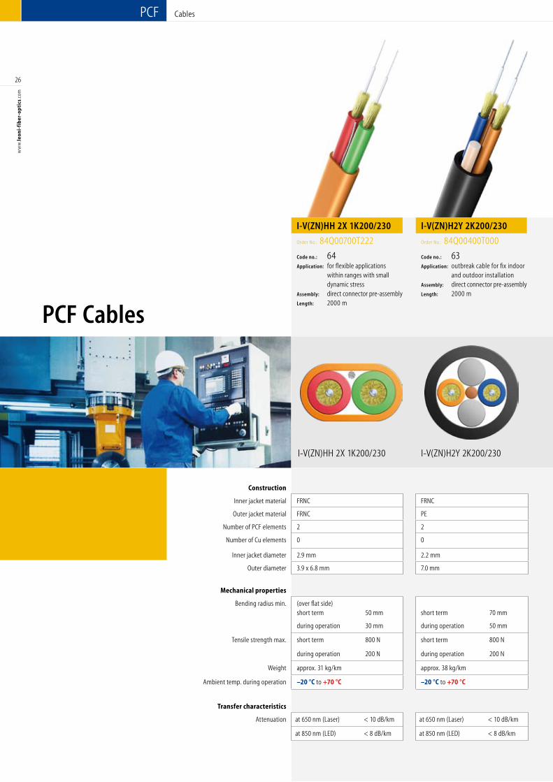
Construction
Inner jacket material PVC
Outer jacket material PVC PUR PVC FRNC PVC
Number of PCF elements 1 1 2 2 1
Inner jacket diameter 2.2 mm
Outer diameter 2.2 mm 3.0 mm 2.2 x 4.5 mm 2.2 x 4.5 mm 5.0 mm
Mechanical properties
Bending radius min. short term 60 mm short term 60 mm
(over flat side)short term 60 mm
(over flat side)short term 60 mm short term 60 mm
during operation 30 mm during operation 30 mm during operation 30 mm during operation 30 mm during operation 40 mm
Tensile strength max. short term 300 N short term 800 N short term 300 N short term 300 N short term 300 N
during operation 100 N during operation 400 N during operation 100 N during operation 100 N during operation 100 N
Weight approx. 5 kg/km approx. 6.5 kg/km approx. 10 kg/km approx. 11 kg/km approx. 28 kg/km
Ambient temp. during operation –20 °C to +70 °C –20 °C to +70 °C –20 °C to +70 °C –20 °C to +70 °C –20 °C to +70 °C
Transfer characteristics
Attenuation at 650 nm (Laser) < 10 dB/km at 650 nm (Laser) < 10 dB/km at 650 nm (Laser) < 10 dB/km at 650 nm (Laser) < 10 dB/km at 650 nm (Laser) < 10 dB/km
at 850 nm (LED) < 8 dB/km at 850 nm (LED) < 8 dB/km at 850 nm (LED) < 8 dB/km at 850 nm (LED) < 8 dB/km at 850 nm (LED) < 8 dB/km
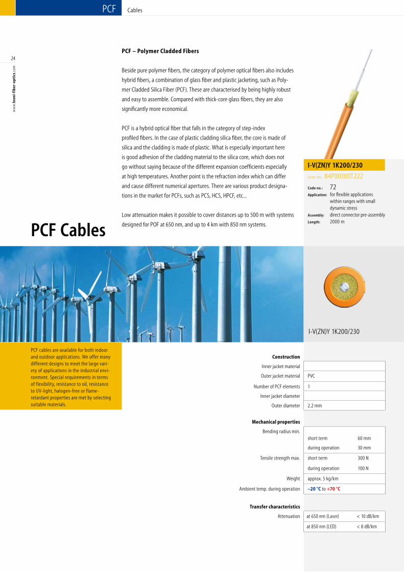
PCF – Polymer Cladded Fibers
Beside pure polymer fibers, the category of polymer optical fibers also includes
hybrid fibers, a combination of glass fiber and plastic jacketing, such as Poly-
mer Cladded Silica Fiber (PCF). These are characterised by being highly robust
and easy to assemble. Compared with thick-core glass fibers, they are also
significantly more economical.
PCF is a hybrid optical fiber that falls in the category of step-index
profiled fibers. In the case of plastic cladding silica fiber, the core is made of
silica and the cladding is made of plastic. What is especially important here
is good adhesion of the cladding material to the silica core, which does not
go without saying because of the different expansion coefficients especially
at high temperatures. Another point is the refraction index which can differ
and cause different numerical apertures. There are various product designa-
tions in the market for PCFs, such as PCS, HCS, HPCF, etc...
Low attenuation makes it possible to cover distances up to 500 m with systems
designed for POF at 650 nm, and up to 4 km with 850 nm systems.
PCF cables are available for both indoor and outdoor applications. We offer many different designs to meet the large vari-ety of applications in the industrial envi-ronment. Special requirements in terms of flexibility, resistance to oil, resistance to UV-light, halogen-free or flame- retardant properties are met by selecting suitable materials.
I-V(ZN)Y 1K200/230
I-V(ZN)Y 1K200/230
Order No.: 84P00300T222
Code no.: 72Application: for flexible applications within ranges with small dynamic stressAssembly: direct connector pre-assembly Length: 2000 m
25
ww
w.le
oni-
fib
er-o
ptic
s.co
m
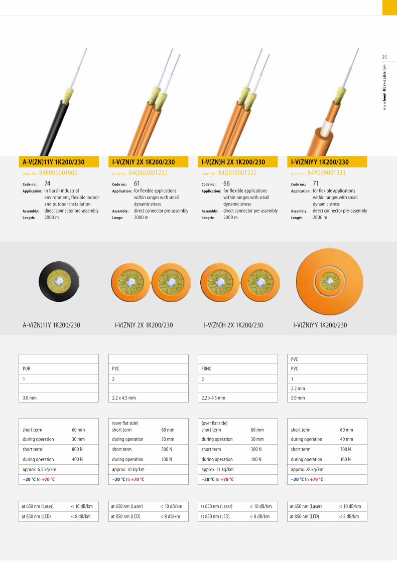
Construction
Inner jacket material PVC
Outer jacket material PVC PUR PVC FRNC PVC
Number of PCF elements 1 1 2 2 1
Inner jacket diameter 2.2 mm
Outer diameter 2.2 mm 3.0 mm 2.2 x 4.5 mm 2.2 x 4.5 mm 5.0 mm
Mechanical properties
Bending radius min. short term 60 mm short term 60 mm
(over flat side)short term 60 mm
(over flat side)short term 60 mm short term 60 mm
during operation 30 mm during operation 30 mm during operation 30 mm during operation 30 mm during operation 40 mm
Tensile strength max. short term 300 N short term 800 N short term 300 N short term 300 N short term 300 N
during operation 100 N during operation 400 N during operation 100 N during operation 100 N during operation 100 N
Weight approx. 5 kg/km approx. 6.5 kg/km approx. 10 kg/km approx. 11 kg/km approx. 28 kg/km
Ambient temp. during operation –20 °C to +70 °C –20 °C to +70 °C –20 °C to +70 °C –20 °C to +70 °C –20 °C to +70 °C
Transfer characteristics
Attenuation at 650 nm (Laser) < 10 dB/km at 650 nm (Laser) < 10 dB/km at 650 nm (Laser) < 10 dB/km at 650 nm (Laser) < 10 dB/km at 650 nm (Laser) < 10 dB/km
at 850 nm (LED) < 8 dB/km at 850 nm (LED) < 8 dB/km at 850 nm (LED) < 8 dB/km at 850 nm (LED) < 8 dB/km at 850 nm (LED) < 8 dB/km
A-V(ZN)11Y 1K200/230 I-V(ZN)Y 2X 1K200/230 I-V(ZN)H 2X 1K200/230 I-V(ZN)YY 1K200/230
A-V(ZN)11Y 1K200/230
Order No.: 84P00600T000
Code no.: 74Application: in harsh industrial environment, flexible indoor and outdoor installation Assembly: direct connector pre-assemblyLength: 2000 m
I-V(ZN)Y 2X 1K200/230
Order No.: 84Q00300T222
Code no.: 61Application: for flexible applications within ranges with small dynamic stressAssembly: direct connector pre-assembly Länge: 2000 m
I-V(ZN)H 2X 1K200/230
Order No.: 84Q01000T222
Code no.: 66Application: for flexible applications within ranges with small dynamic stressAssembly: direct connector pre-assemblyLength: 2000 m
I-V(ZN)YY 1K200/230
Order No.: 84P00900T333
Code no.: 71Application: for flexible applications within ranges with small dynamic stressAssembly: direct connector pre-assemblyLength: 2000 m
26
ww
w.le
oni-
fib
er-o
ptic
s.co
mPCF
Construction
Inner jacket material FRNC FRNC FRNC FRNC PVC
Outer jacket material FRNC PE PE PUR PUR
Number of PCF elements 2 2 2 2 2
Number of Cu elements 0 0 0 0 2
Inner jacket diameter 2.9 mm 2.2 mm 2.9 mm 2.2 mm 2.2 mm
Outer diameter 3.9 x 6.8 mm 7.0 mm 10.5 mm 7.4 mm 7.6 mm
Mechanical properties
Bending radius min. (over flat side)short term 50 mm short term 70 mm
short term 150 mm short term 70 mm short term 70 mm
during operation 30 mm during operation 50 mm during operation 200 mm during operation 50 mm during operation 50 mm
Tensile strength max. short term 800 N short term 800 N short term 1500 N short term 800 N short term 800 N
during operation 200 N during operation 200 N during operation 500 N during operation 200 N during operation 200 N
Weight approx. 31 kg/km approx. 38 kg/km approx. 90 kg/km approx. 45 kg/km approx. 65 kg/km
Ambient temp. during operation –20 °C to +70 °C –20 °C to +70 °C –20 °C to +70 °C –20 °C to +70 °C –20 °C to +70 °C
Transfer characteristics
Attenuation at 650 nm (Laser) < 10 dB/km at 650 nm (Laser) < 10 dB/km at 650 nm (Laser) < 10 dB/km at 650 nm (Laser) < 10 dB/km at 650 nm (Laser) < 10 dB/km
at 850 nm (LED) < 8 dB/km at 850 nm (LED) < 8 dB/km at 850 nm (LED) < 8 dB/km at 850 nm (LED) < 8 dB/km at 850 nm (LED) < 8 dB/km
I-V(ZN)H2Y 2K200/230
PCF Cables
Cables
I-V(ZN)HH 2X 1K200/230
I-V(ZN)HH 2X 1K200/230
Order No.: 84Q00700T222
Code no.: 64Application: for flexible applications within ranges with small dynamic stressAssembly: direct connector pre-assemblyLength: 2000 m
I-V(ZN)H2Y 2K200/230
Order No.: 84Q00400T000
Code no.: 63Application: outbreak cable for fix indoor and outdoor installationAssembly: direct connector pre-assemblyLength: 2000 m
27
ww
w.le
oni-
fib
er-o
ptic
s.co
m
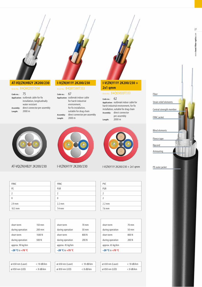
Construction
Inner jacket material FRNC FRNC FRNC FRNC PVC
Outer jacket material FRNC PE PE PUR PUR
Number of PCF elements 2 2 2 2 2
Number of Cu elements 0 0 0 0 2
Inner jacket diameter 2.9 mm 2.2 mm 2.9 mm 2.2 mm 2.2 mm
Outer diameter 3.9 x 6.8 mm 7.0 mm 10.5 mm 7.4 mm 7.6 mm
Mechanical properties
Bending radius min. (over flat side)short term 50 mm short term 70 mm
short term 150 mm short term 70 mm short term 70 mm
during operation 30 mm during operation 50 mm during operation 200 mm during operation 50 mm during operation 50 mm
Tensile strength max. short term 800 N short term 800 N short term 1500 N short term 800 N short term 800 N
during operation 200 N during operation 200 N during operation 500 N during operation 200 N during operation 200 N
Weight approx. 31 kg/km approx. 38 kg/km approx. 90 kg/km approx. 45 kg/km approx. 65 kg/km
Ambient temp. during operation –20 °C to +70 °C –20 °C to +70 °C –20 °C to +70 °C –20 °C to +70 °C –20 °C to +70 °C
Transfer characteristics
Attenuation at 650 nm (Laser) < 10 dB/km at 650 nm (Laser) < 10 dB/km at 650 nm (Laser) < 10 dB/km at 650 nm (Laser) < 10 dB/km at 650 nm (Laser) < 10 dB/km
at 850 nm (LED) < 8 dB/km at 850 nm (LED) < 8 dB/km at 850 nm (LED) < 8 dB/km at 850 nm (LED) < 8 dB/km at 850 nm (LED) < 8 dB/km
AT-VQ(ZN)HB2Y 2K200/230 I-V(ZN)H11Y 2K200/230 PE outer jacket
Ripcord
Blind elements
Fiber
Strain relief elements
I-V(ZN)Y11Y 2K200/230 + 2x1 qmm
Armouring
Fleece tape
Central strength member
FRNC jacket
AT-VQ(ZN)HB2Y 2K200/230
Order No.: 84Q00200T000
Code no.: 75Application: outbreak cable for fix installation, longitudinally water resistant Assembly: direct connector pre-assemblyLength: 2000 m
I-V(ZN)H11Y 2K200/230
Order No.: 84Q01500T333
Code no.: 67Application: outbreak indoor cable for harsh industrial environment, for fix installation, suitable for drag chain Assembly: direct connector pre-assembly Length: 2000 m
I-V(ZN)Y11Y 2K200/230 + 2x1 qmm
Order No.: 84Q03000T333
Code no.: 62Application: outbreak indoor cable for harsh industrial environment, for fix installation, suitable for drag chainAssembly: direct connector pre-assemblyLength: 2000 m
28
ww
w.le
oni-
fib
er-o
ptic
s.co
mPCF
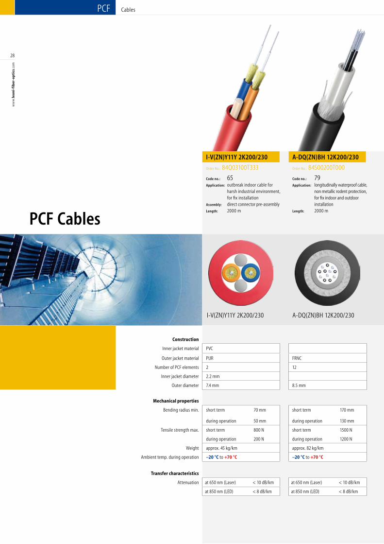
Construction
Inner jacket material PVC
Outer jacket material PUR FRNC PE
Number of PCF elements 2 12 2
Inner jacket diameter 2.2 mm
Outer diameter 7.4 mm 8.5 mm 7.5 mm
Mechanical properties
Bending radius min. short term 70 mm short term 170 mm short term 150 mm
during operation 50 mm during operation 130 mm during operation 110 mm
Tensile strength max. short term 800 N short term 1500 N short term 1500 N
during operation 200 N during operation 1200 N during operation 1200 N
Weight approx. 45 kg/km approx. 82 kg/km approx. 47 kg/km
Ambient temp. during operation –20 °C to +70 °C –20 °C to +70 °C –20 °C to +70 °C
Transfer characteristics
Attenuation at 650 nm (Laser) < 10 dB/km at 650 nm (Laser) < 10 dB/km at 650 nm (Laser) < 10 dB/km
at 850 nm (LED) < 8 dB/km at 850 nm (LED) < 8 dB/km at 850 nm (LED) < 8 dB/km
A-DQ(ZN)BH 12K200/230
PCF Cables
Cables
I-V(ZN)Y11Y 2K200/230
I-V(ZN)Y11Y 2K200/230
Order No.: 84Q03100T333
Code no.: 65Application: outbreak indoor cable for harsh industrial environment, for fix installationAssembly: direct connector pre-assemblyLength: 2000 m
A-DQ(ZN)BH 12K200/230
Order No.: 84S00200T000
Code no.: 79Application: longitudinally waterproof cable, non metallic rodent protection, for fix indoor and outdoor installation Length: 2000 m
29
ww
w.le
oni-
fib
er-o
ptic
s.co
m
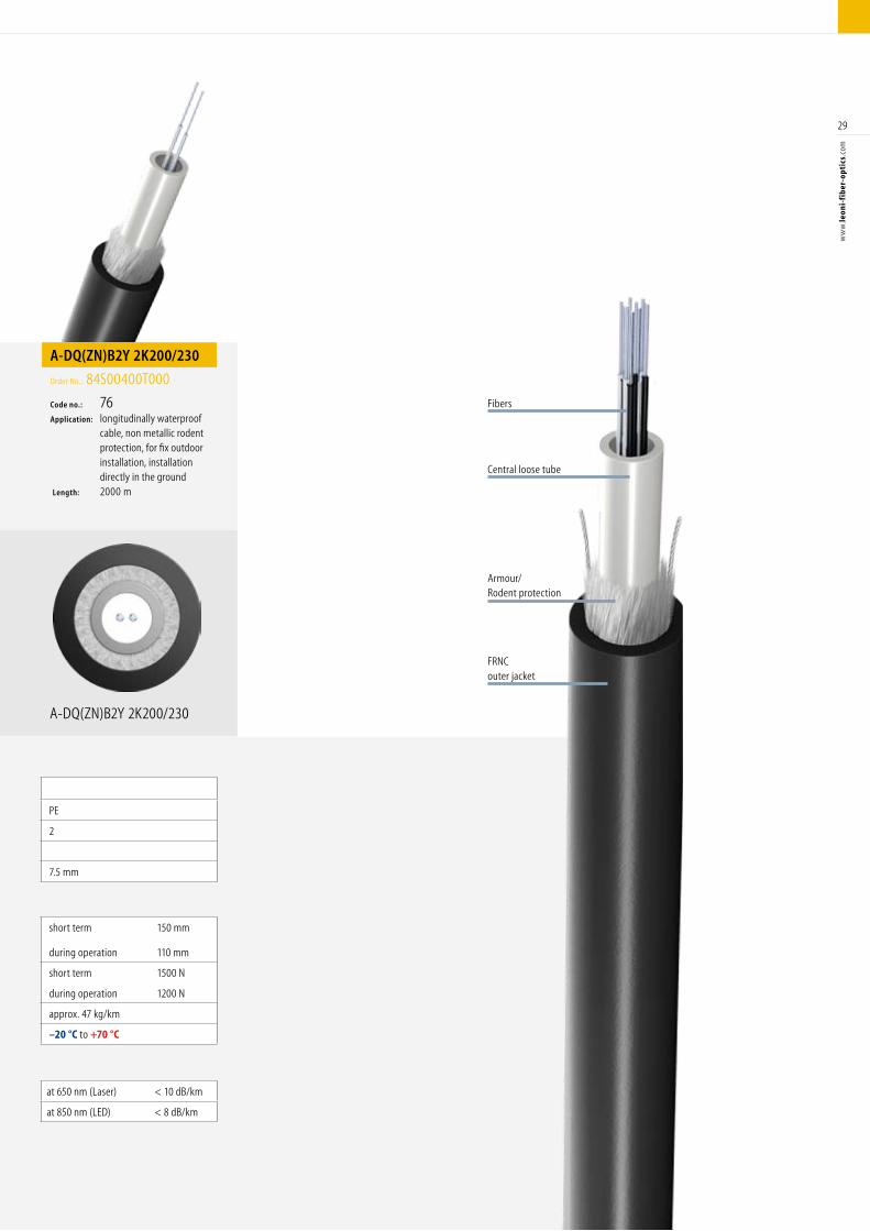
Construction
Inner jacket material PVC
Outer jacket material PUR FRNC PE
Number of PCF elements 2 12 2
Inner jacket diameter 2.2 mm
Outer diameter 7.4 mm 8.5 mm 7.5 mm
Mechanical properties
Bending radius min. short term 70 mm short term 170 mm short term 150 mm
during operation 50 mm during operation 130 mm during operation 110 mm
Tensile strength max. short term 800 N short term 1500 N short term 1500 N
during operation 200 N during operation 1200 N during operation 1200 N
Weight approx. 45 kg/km approx. 82 kg/km approx. 47 kg/km
Ambient temp. during operation –20 °C to +70 °C –20 °C to +70 °C –20 °C to +70 °C
Transfer characteristics
Attenuation at 650 nm (Laser) < 10 dB/km at 650 nm (Laser) < 10 dB/km at 650 nm (Laser) < 10 dB/km
at 850 nm (LED) < 8 dB/km at 850 nm (LED) < 8 dB/km at 850 nm (LED) < 8 dB/km
A-DQ(ZN)B2Y 2K200/230
FRNCouter jacket
Fibers
Armour/Rodent protection
Central loose tube
A-DQ(ZN)B2Y 2K200/230
Order No.: 84S00400T000
Code no.: 76Application: longitudinally waterproof cable, non metallic rodent protection, for fix outdoor installation, installation directly in the ground Length: 2000 m
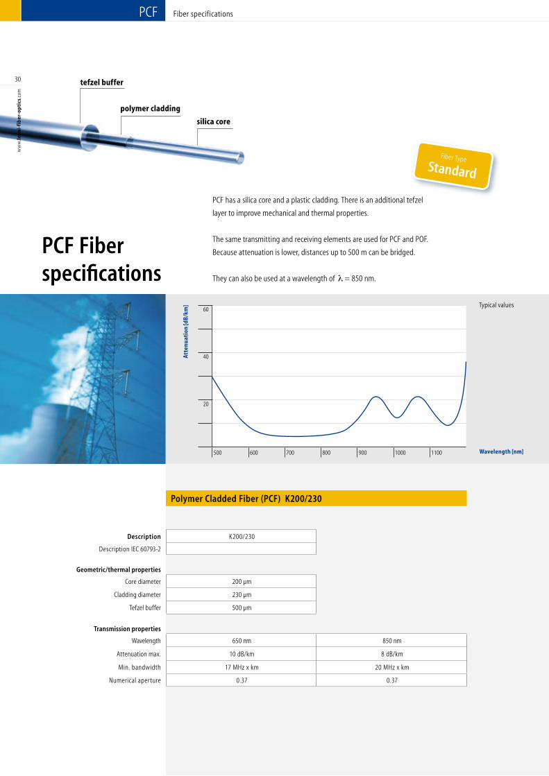
Fiber specificationsPCF
60
40
20
500 600 700 800 900 1000 1100
Atte
nuat
ion
[dB/
km]
Wavelength [nm]
Typical values
30
ww
w.le
oni-
fib
er-o
ptic
s.co
m
PCF Fiber specifications
Description K200/230
Description IEC 60793-2
Geometric/thermal properties
Core diameter 200 µm
Cladding diameter 230 µm
Tefzel buffer 500 µm
Transmission properties
Wavelength 650 nm 850 nm
Attenuation max. 10 dB/km 8 dB/km
Min. bandwidth 17 MHz x km 20 MHz x km
Numerical aperture 0.37 0.37
silica core
tefzel buffer
Polymer Cladded Fiber (PCF) K200/230
polymer cladding
Fiber TypeStandard
PCF has a silica core and a plastic cladding. There is an additional tefzel
layer to improve mechanical and thermal properties.
The same transmitting and receiving elements are used for PCF and POF.
Because attenuation is lower, distances up to 500 m can be bridged.
They can also be used at a wavelength of = 850 nm.
Wavelength [nm]
31
ww
w.le
oni-
fib
er-o
ptic
s.co
m
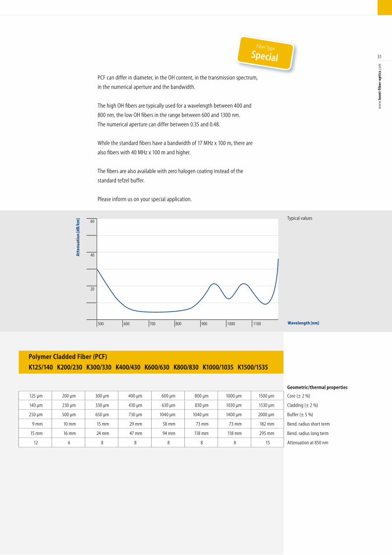
60
40
20
500 600 700 800 900 1000 1100
Atte
nuat
ion
[dB/
km]
Wavelength [nm]
Typical values
Polymer Cladded Fiber (PCF)
K125/140 K200/230 K300/330 K400/430 K600/630 K800/830 K1000/1035 K1500/1535
PCF can differ in diameter, in the OH content, in the transmission spectrum,
in the numerical aperture and the bandwidth.
The high OH fibers are typically used for a wavelength between 400 and
800 nm, the low OH fibers in the range between 600 and 1300 nm.
The numerical aperture can differ between 0.35 and 0.48.
While the standard fibers have a bandwidth of 17 MHz x 100 m, there are
also fibers with 40 MHz x 100 m and higher.
The fibers are also available with zero halogen coating instead of the
standard tefzel buffer.
Please inform us on your special application.
Geometric/thermal properties
125 µm 200 µm 300 µm 400 µm 600 µm 800 µm 1000 µm 1500 µm Core (± 2 %)
140 µm 230 µm 330 µm 430 µm 630 µm 830 µm 1030 µm 1530 µm Cladding (± 2 %)
250 µm 500 µm 650 µm 730 µm 1040 µm 1040 µm 1400 µm 2000 µm Buffer (± 5 %)
9 mm 10 mm 15 mm 29 mm 58 mm 73 mm 73 mm 182 mm Bend. radius short term
15 mm 16 mm 24 mm 47 mm 94 mm 118 mm 118 mm 295 mm Bend. radius long term
12 6 8 8 8 8 8 15 Attenuation at 850 nm
Fiber Type
Special
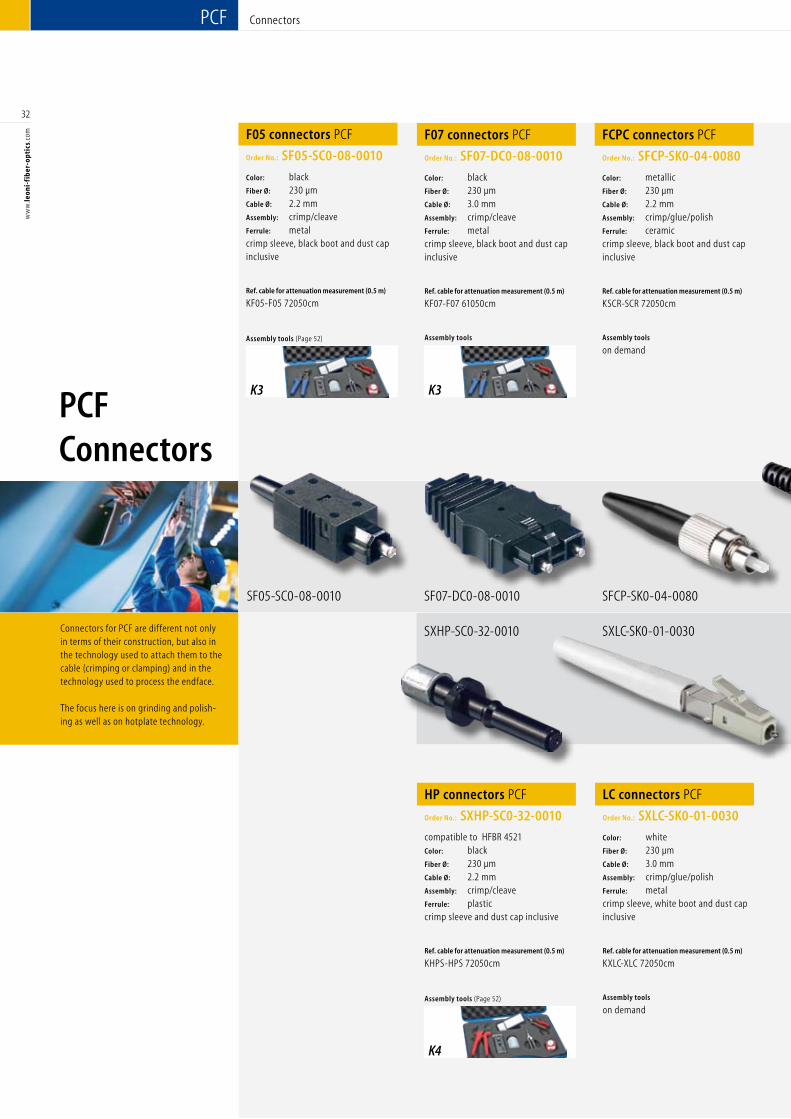
Connectors for PCF are different not only in terms of their construction, but also in the technology used to attach them to the cable (crimping or clamping) and in the technology used to process the endface. The focus here is on grinding and polish-ing as well as on hotplate technology.
PCF Connectors
32
ww
w.le
oni-
fib
er-o
ptic
s.co
mPCF Connectors
F05 connectors PCF
Order No.: SF05-SC0-08-0010
Color: black Fiber Ø: 230 µm Cable Ø: 2.2 mm Assembly: crimp/cleave Ferrule: metalcrimp sleeve, black boot and dust cap inclusive
Ref. cable for attenuation measurement (0.5 m)
KF05-F05 72050cm
Assembly tools (Page 52)
SF05-SC0-08-0010
F07 connectors PCF
Order No.: SF07-DC0-08-0010
Color: black Fiber Ø: 230 µm Cable Ø: 3.0 mm Assembly: crimp/cleave Ferrule: metalcrimp sleeve, black boot and dust cap inclusive
Ref. cable for attenuation measurement (0.5 m)
KF07-F07 61050cm
Assembly tools
FCPC connectors PCF
Order No.: SFCP-SK0-04-0080
Color: metallic Fiber Ø: 230 µm Cable Ø: 2.2 mm Assembly: crimp/glue/polishFerrule: ceramic crimp sleeve, black boot and dust cap inclusive
Ref. cable for attenuation measurement (0.5 m)
KSCR-SCR 72050cm
Assembly tools
on demand
HP connectors PCF
Order No.: SXHP-SC0-32-0010
compatible to HFBR 4521 Color: blackFiber Ø: 230 µm Cable Ø: 2.2 mm Assembly: crimp/cleaveFerrule: plastic crimp sleeve and dust cap inclusive
Ref. cable for attenuation measurement (0.5 m)
KHPS-HPS 72050cm
Assembly tools (Page 52)
LC connectors PCF
Order No.: SXLC-SK0-01-0030
Color: whiteFiber Ø: 230 µm Cable Ø: 3.0 mm Assembly: crimp/glue/polishFerrule: metalcrimp sleeve, white boot and dust cap inclusive
Ref. cable for attenuation measurement (0.5 m)
KXLC-XLC 72050cm
Assembly tools
on demand
SF07-DC0-08-0010 SFCP-SK0-04-0080
SXHP-SC0-32-0010 SXLC-SK0-01-0030
K3
K4
K3
33
ww
w.le
oni-
fib
er-o
ptic
s.co
m
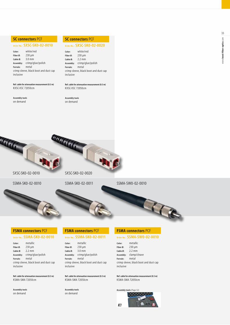
SXSC-SK0-02-0010
SSMA-SK0-02-0010
SXSC-SK0-02-0020
SSMA-SK0-02-0011 SSMA-SW0-02-0010
SC connectors PCF
Order No.: SXSC-SK0-02-0010
Color: white/red Fiber Ø: 230 µm Cable Ø: 3.0 mm Assembly: crimp/glue/polishFerrule: metalcrimp sleeve, black boot and dust cap inclusive
Ref. cable for attenuation measurement (0.5 m)
KXSC-XSC 72050cm
Assembly tools
on demand
SC connectors PCF
Order No.: SXSC-SK0-02-0020
Color: white/redFiber Ø: 230 µm Cable Ø: 2.2 mm Assembly: crimp/glue/polishFerrule: metalcrimp sleeve, black boot and dust cap inclusive
Ref. cable for attenuation measurement (0.5 m)
KXSC-XSC 72050cm
Assembly tools
on demand
FSMA connectors PCF
Order No.: SSMA-SK0-02-0010
Color: metallic Fiber Ø: 230 µm Cable Ø: 2.2 mm Assembly: crimp/glue/polishFerrule: metalcrimp sleeve, black boot and dust cap inclusive
Ref. cable for attenuation measurement (0.5 m)
KSMA-SMA 72050cm
Assembly tools
on demand
FSMA connectors PCF
Order No.: SSMA-SK0-02-0011
Color: metallic Fiber Ø: 230 µm Cable Ø: 3.0 mm Assembly: crimp/glue/polishFerrule: metalcrimp sleeve, black boot and dust cap inclusive
Ref. cable for attenuation measurement (0.5 m)
KSMA-SMA 72050cm
Assembly tools
on demand
FSMA connectors PCF
Order No.: SSMA-SW0-02-0010
Color: metallic Fiber Ø: 230 µm Cable Ø: 2.2 mm Assembly: clamp/cleaveFerrule: metalcrimp sleeve, black boot and dust cap inclusive
Ref. cable for attenuation measurement (0.5 m)
KSMA-SMA 72050cm
Assembly tools (Page 52)
K1
PCF Connectors
34
ww
w.le
oni-
fib
er-o
ptic
s.co
mPCF Connectors
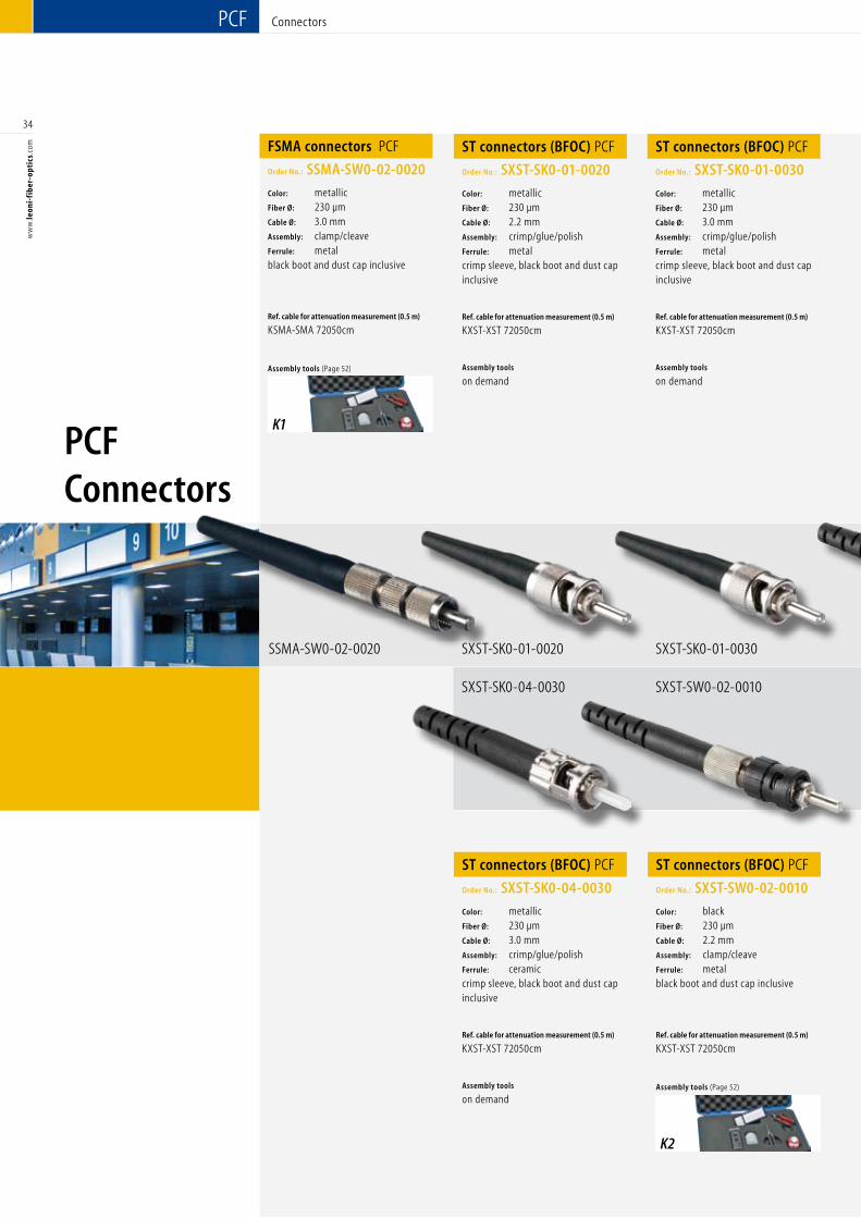
FSMA connectors PCF
Order No.: SSMA-SW0-02-0020
Color: metallic Fiber Ø: 230 µm Cable Ø: 3.0 mm Assembly: clamp/cleave Ferrule: metalblack boot and dust cap inclusive
Ref. cable for attenuation measurement (0.5 m)
KSMA-SMA 72050cm
Assembly tools (Page 52)
SSMA-SW0-02-0020
ST connectors (BFOC) PCF
Order No.: SXST-SK0-01-0020
Color: metallic Fiber Ø: 230 µm Cable Ø: 2.2 mm Assembly: crimp/glue/polish Ferrule: metalcrimp sleeve, black boot and dust cap inclusive
Ref. cable for attenuation measurement (0.5 m)
KXST-XST 72050cm
Assembly tools
on demand
ST connectors (BFOC) PCF
Order No.: SXST-SK0-01-0030
Color: metallic Fiber Ø: 230 µm Cable Ø: 3.0 mm Assembly: crimp/glue/polish Ferrule: metalcrimp sleeve, black boot and dust cap inclusive
Ref. cable for attenuation measurement (0.5 m)
KXST-XST 72050cm
Assembly tools
on demand
ST connectors (BFOC) PCF
Order No.: SXST-SK0-04-0030
Color: metallicFiber Ø: 230 µm Cable Ø: 3.0 mm Assembly: crimp/glue/polishFerrule: ceramiccrimp sleeve, black boot and dust cap inclusive
Ref. cable for attenuation measurement (0.5 m)
KXST-XST 72050cm
Assembly tools
on demand
ST connectors (BFOC) PCF
Order No.: SXST-SW0-02-0010
Color: blackFiber Ø: 230 µm Cable Ø: 2.2 mm Assembly: clamp/cleaveFerrule: metalblack boot and dust cap inclusive
Ref. cable for attenuation measurement (0.5 m)
KXST-XST 72050cm
Assembly tools (Page 52)
SXST-SK0-01-0020 SXST-SK0-01-0030
SXST-SK0-04-0030 SXST-SW0-02-0010
K1
K2
35
ww
w.le
oni-
fib
er-o
ptic
s.co
m
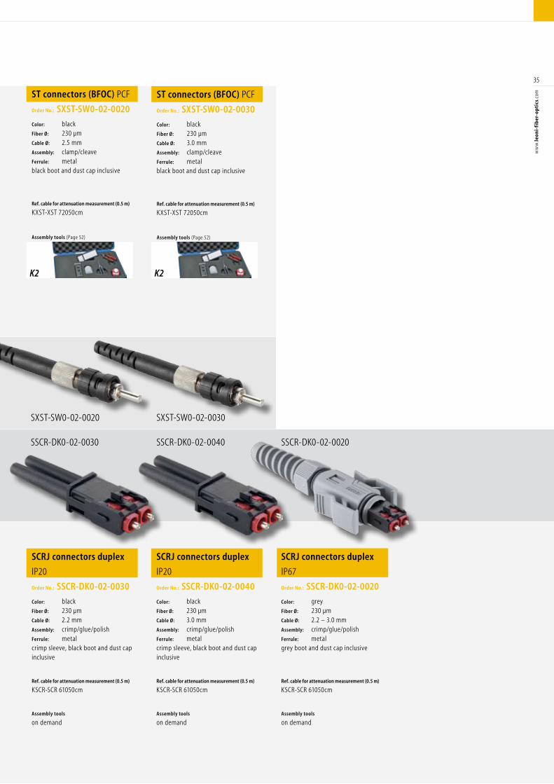
SXST-SW0-02-0020
SSCR-DK0-02-0030
SXST-SW0-02-0030
SSCR-DK0-02-0040 SSCR-DK0-02-0020
ST connectors (BFOC) PCF
Order No.: SXST-SW0-02-0020
Color: blackFiber Ø: 230 µm Cable Ø: 2.5 mm Assembly: clamp/cleaveFerrule: metalblack boot and dust cap inclusive
Ref. cable for attenuation measurement (0.5 m)
KXST-XST 72050cm
Assembly tools (Page 52)
ST connectors (BFOC) PCF
Order No.: SXST-SW0-02-0030
Color: blackFiber Ø: 230 µm Cable Ø: 3.0 mm Assembly: clamp/cleaveFerrule: metalblack boot and dust cap inclusive
Ref. cable for attenuation measurement (0.5 m)
KXST-XST 72050cm
Assembly tools (Page 52)
SCRJ connectors duplex
IP20
Order No.: SSCR-DK0-02-0030
Color: blackFiber Ø: 230 µm Cable Ø: 2.2 mm Assembly: crimp/glue/polishFerrule: metalcrimp sleeve, black boot and dust cap inclusive
Ref. cable for attenuation measurement (0.5 m)
KSCR-SCR 61050cm
Assembly tools
on demand
SCRJ connectors duplex
IP20
Order No.: SSCR-DK0-02-0040
Color: blackFiber Ø: 230 µm Cable Ø: 3.0 mm Assembly: crimp/glue/polishFerrule: metalcrimp sleeve, black boot and dust cap inclusive
Ref. cable for attenuation measurement (0.5 m)
KSCR-SCR 61050cm
Assembly tools
on demand
SCRJ connectors duplex
IP67
Order No.: SSCR-DK0-02-0020
Color: grey Fiber Ø: 230 µm Cable Ø: 2.2 – 3.0 mm Assembly: crimp/glue/polishFerrule: metalgrey boot and dust cap inclusive
Ref. cable for attenuation measurement (0.5 m)
KSCR-SCR 61050cm
Assembly tools
on demand
K2 K2
36
ww
w.le
oni-
fib
er-o
ptic
s.co
m
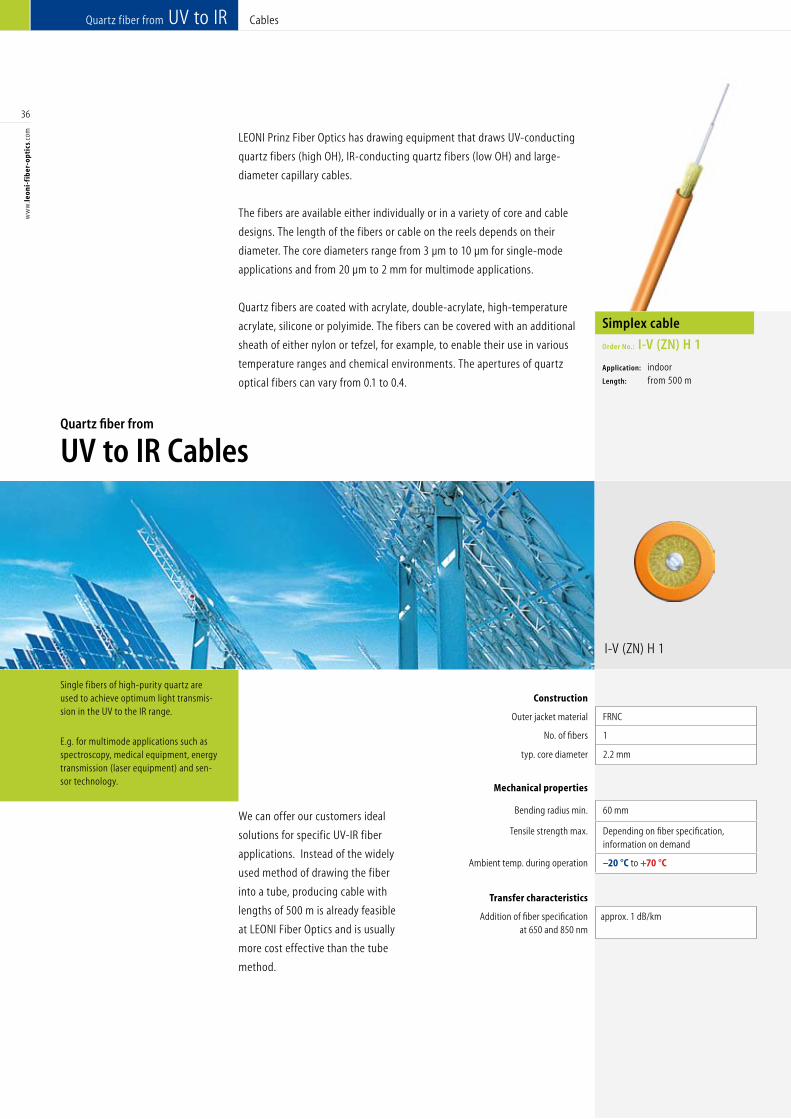
I-V (ZN) H 1
Single fibers of high-purity quartz are used to achieve optimum light transmis-sion in the UV to the IR range.
E.g. for multimode applications such as spectroscopy, medical equipment, energy transmission (laser equipment) and sen-sor technology.
LEONI Prinz Fiber Optics has drawing equipment that draws UV-conducting
quartz fibers (high OH), IR-conducting quartz fibers (low OH) and large-
diameter capillary cables.
The fibers are available either individually or in a variety of core and cable
designs. The length of the fibers or cable on the reels depends on their
diameter. The core diameters range from 3 µm to 10 µm for single-mode
applications and from 20 µm to 2 mm for multimode applications.
Quartz fibers are coated with acrylate, double-acrylate, high-temperature
acrylate, silicone or polyimide. The fibers can be covered with an additional
sheath of either nylon or tefzel, for example, to enable their use in various
temperature ranges and chemical environments. The apertures of quartz
optical fibers can vary from 0.1 to 0.4.
We can offer our customers ideal
solutions for specific UV-IR fiber
applications. Instead of the widely
used method of drawing the fiber
into a tube, producing cable with
lengths of 500 m is already feasible
at LEONI Fiber Optics and is usually
more cost effective than the tube
method.
Quartz fiber from UV to IR Cables
Quartz fiber from
UV to IR Cables
Simplex cable
Order No.: I-V (ZN) H 1
Application: indoorLength: from 500 m
Construction
Outer jacket material FRNC PUR PVC FRNC Silicone
No. of fibers 1 1 2 2 ≥ 1
typ. core diameter 2.2 mm 2.2 mm 2.2 x 4.5 mm 2.2 x 4.5 mm ≥ 4.6 mm
Mechanical properties
Bending radius min. 60 mm 60 mm 60 mm 60 mm 100 mm
Tensile strength max. Depending on fiber specification, information on demand
Depending on fiber specification, information on demand
Depending on fiber specification, information on demand
Depending on fiber specification, information on demand
Depending on fiber specification, information on demand
Ambient temp. during operation –20 °C to +70 °C –20 °C to +70 °C –20 °C to +70 °C –20 °C to +70 °C –20 °C to +70 °C
Transfer characteristics
Addition of fiber specification at 650 and 850 nm
approx. 1 dB/km approx. 2 dB/km approx. 2 dB/km approx. 2 dB/km approx. 1 dB/km
37
ww
w.le
oni-
fib
er-o
ptic
s.co
m
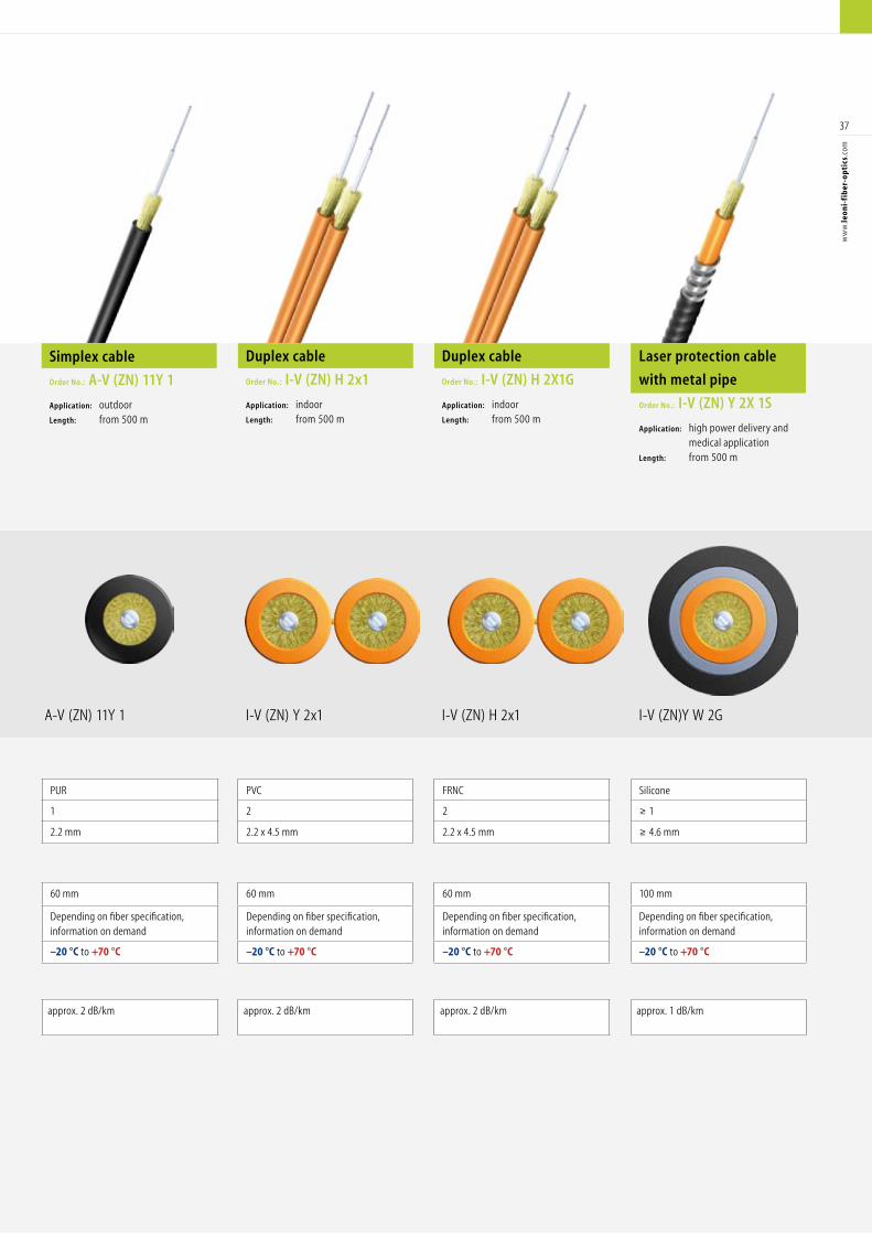
I-V (ZN) Y 2x1 I-V (ZN)Y W 2G I-V (ZN) H 2x1 A-V (ZN) 11Y 1
Duplex cable
Order No.: I-V (ZN) H 2x1
Application: indoorLength: from 500 m
Laser protection cable
with metal pipe
Order No.: I-V (ZN) Y 2X 1S
Application: high power delivery and medical applicationLength: from 500 m
Duplex cable
Order No.: I-V (ZN) H 2X1G
Application: indoor Length: from 500 m
Simplex cable
Order No.: A-V (ZN) 11Y 1
Application: outdoor Length: from 500 m
Construction
Outer jacket material FRNC PUR PVC FRNC Silicone
No. of fibers 1 1 2 2 ≥ 1
typ. core diameter 2.2 mm 2.2 mm 2.2 x 4.5 mm 2.2 x 4.5 mm ≥ 4.6 mm
Mechanical properties
Bending radius min. 60 mm 60 mm 60 mm 60 mm 100 mm
Tensile strength max. Depending on fiber specification, information on demand
Depending on fiber specification, information on demand
Depending on fiber specification, information on demand
Depending on fiber specification, information on demand
Depending on fiber specification, information on demand
Ambient temp. during operation –20 °C to +70 °C –20 °C to +70 °C –20 °C to +70 °C –20 °C to +70 °C –20 °C to +70 °C
Transfer characteristics
Addition of fiber specification at 650 and 850 nm
approx. 1 dB/km approx. 2 dB/km approx. 2 dB/km approx. 2 dB/km approx. 1 dB/km
I-V (ZN) H 2Y I-V (ZN)Y W Y
38
ww
w.le
oni-
fib
er-o
ptic
s.co
m
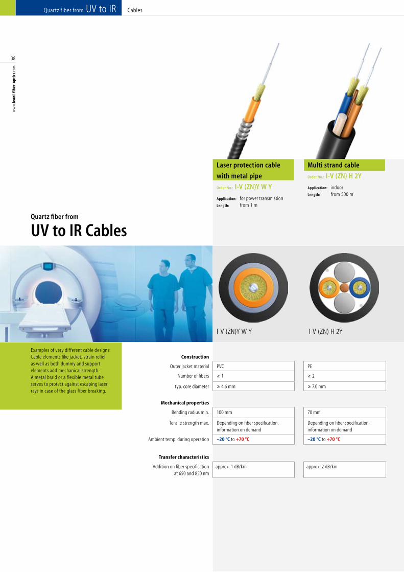
Examples of very different cable designs: Cable elements like jacket, strain relief as well as both dummy and support elements add mechanical strength. A metal braid or a flexible metal tube serves to protect against escaping laser rays in case of the glass fiber breaking.
Quartz fiber from UV to IR Cables
Quartz fiber from
UV to IR Cables
Laser protection cable
with metal pipe
Order No.: I-V (ZN)Y W Y
Application: for power transmissionLength: from 1 m
Multi strand cable
Order No.: I-V (ZN) H 2Y
Application: indoorLength: from 500 m
Construction
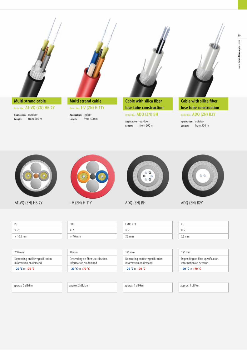
Outer jacket material PVC PE PE PUR FRNC / PE PE
Number of fibers ≥ 1 ≥ 2 ≥ 2 ≥ 2 ≥ 2 ≥ 2
typ. core diameter ≥ 4.6 mm ≥ 7.0 mm ≥ 10.5 mm ≥ 7.0 mm 7.5 mm 7.5 mm
Mechanical properties
Bending radius min. 100 mm 70 mm 200 mm 70 mm 150 mm 150 mm
Tensile strength max. Depending on fiber specification, information on demand
Depending on fiber specification, information on demand
Depending on fiber specification, information on demand
Depending on fiber specification, information on demand
Depending on fiber specification, information on demand
Depending on fiber specification, information on demand
Ambient temp. during operation –20 °C to +70 °C –20 °C to +70 °C –20 °C to +70 °C –20 °C to +70 °C –20 °C to +70 °C –20 °C to +70 °C
Transfer characteristics
Addition on fiber specification at 650 and 850 nm
approx. 1 dB/km approx. 2 dB/km approx. 2 dB/km approx. 2 dB/km approx. 1 dB/km approx. 1 dB/km
I-V (ZN) H 11Y ADQ (ZN) B2Y ADQ (ZN) BH AT-VQ (ZN) HB 2Y
39
ww
w.le
oni-
fib
er-o
ptic
s.co
m
Multi strand cable
Order No.: I-V (ZN) H 11Y
Application: indoor Length: from 500 m
Cable with silica fiber
lose tube construction
Order No.: ADQ (ZN) B2Y
Application: outdoor Length: from 500 m
Multi strand cable
Order No.: AT-VQ (ZN) HB 2Y
Application: outdoor Length: from 500 m
Cable with silica fiber
lose tube construction
Order No.: ADQ (ZN) BH
Application: outdoorLength: from 500 m
Construction
Outer jacket material PVC PE PE PUR FRNC / PE PE
Number of fibers ≥ 1 ≥ 2 ≥ 2 ≥ 2 ≥ 2 ≥ 2
typ. core diameter ≥ 4.6 mm ≥ 7.0 mm ≥ 10.5 mm ≥ 7.0 mm 7.5 mm 7.5 mm
Mechanical properties
Bending radius min. 100 mm 70 mm 200 mm 70 mm 150 mm 150 mm
Tensile strength max. Depending on fiber specification, information on demand
Depending on fiber specification, information on demand
Depending on fiber specification, information on demand
Depending on fiber specification, information on demand
Depending on fiber specification, information on demand
Depending on fiber specification, information on demand
Ambient temp. during operation –20 °C to +70 °C –20 °C to +70 °C –20 °C to +70 °C –20 °C to +70 °C –20 °C to +70 °C –20 °C to +70 °C
Transfer characteristics
Addition on fiber specification at 650 and 850 nm
approx. 1 dB/km approx. 2 dB/km approx. 2 dB/km approx. 2 dB/km approx. 1 dB/km approx. 1 dB/km
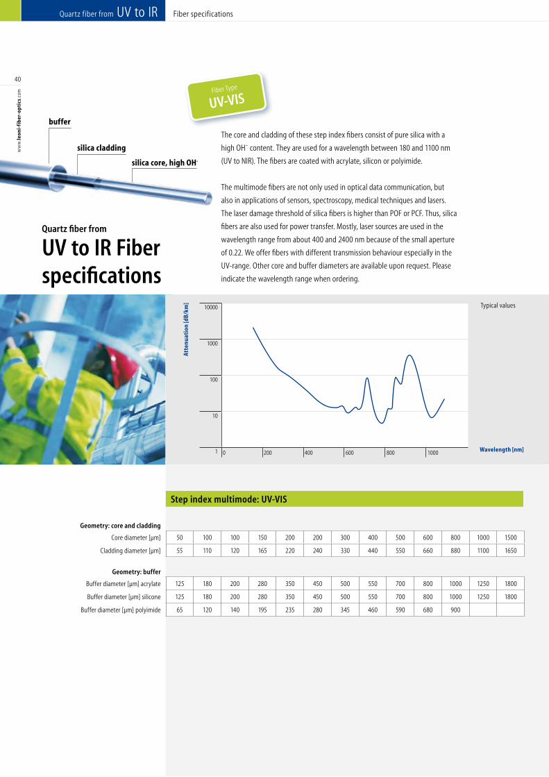
Fiber specifications
Step index multimode: UV-VIS
Quartz fiber from UV to IR
10000
1000
100
10
1 0 200 400 600 800 1000
40
ww
w.le
oni-
fib
er-o
ptic
s.co
m
silica core, high OH-
buffer
Geometry: core and cladding
Core diameter [µm] 50 100 100 150 200 200 300 400 500 600 800 1000 1500 50 100 100 150 200 200 300 400 500 600 800 1000 1500
Cladding diameter [µm] 55 110 120 165 220 240 330 440 550 660 880 1100 1650 70 120 140 165 220 280 330 440 550 660 880 1100 1650
Geometry: buffer
Buffer diameter [µm] acrylate 125 180 200 280 350 450 500 550 700 800 1000 1250 1800 125 180 200 280 350 500 500 550 700 800 1000 1250 1800
Buffer diameter [µm] silicone 125 180 200 280 350 450 500 550 700 800 1000 1250 1800 125 180 200 280 350 500 500 550 700 800 1000 1250 1800
Buffer diameter [µm] polyimide 65 120 140 195 235 280 345 460 590 680 900 85 140 155 195 235 295 345 460 590 680 900
silica cladding
Fiber Type
UV-VIS
Quartz fiber from
UV to IR Fiberspecifications
The core and cladding of these step index fibers consist of pure silica with a
high OH¯ content. They are used for a wavelength between 180 and 1100 nm
(UV to NIR). The fibers are coated with acrylate, silicon or polyimide.
The multimode fibers are not only used in optical data communication, but
also in applications of sensors, spectroscopy, medical techniques and lasers.
The laser damage threshold of silica fibers is higher than POF or PCF. Thus, silica
fibers are also used for power transfer. Mostly, laser sources are used in the
wavelength range from about 400 and 2400 nm because of the small aperture
of 0.22. We offer fibers with different transmission behaviour especially in the
UV-range. Other core and buffer diameters are available upon request. Please
indicate the wavelength range when ordering.
Atte
nuat
ion
[dB/
km]
Wavelength [nm]
Typical values
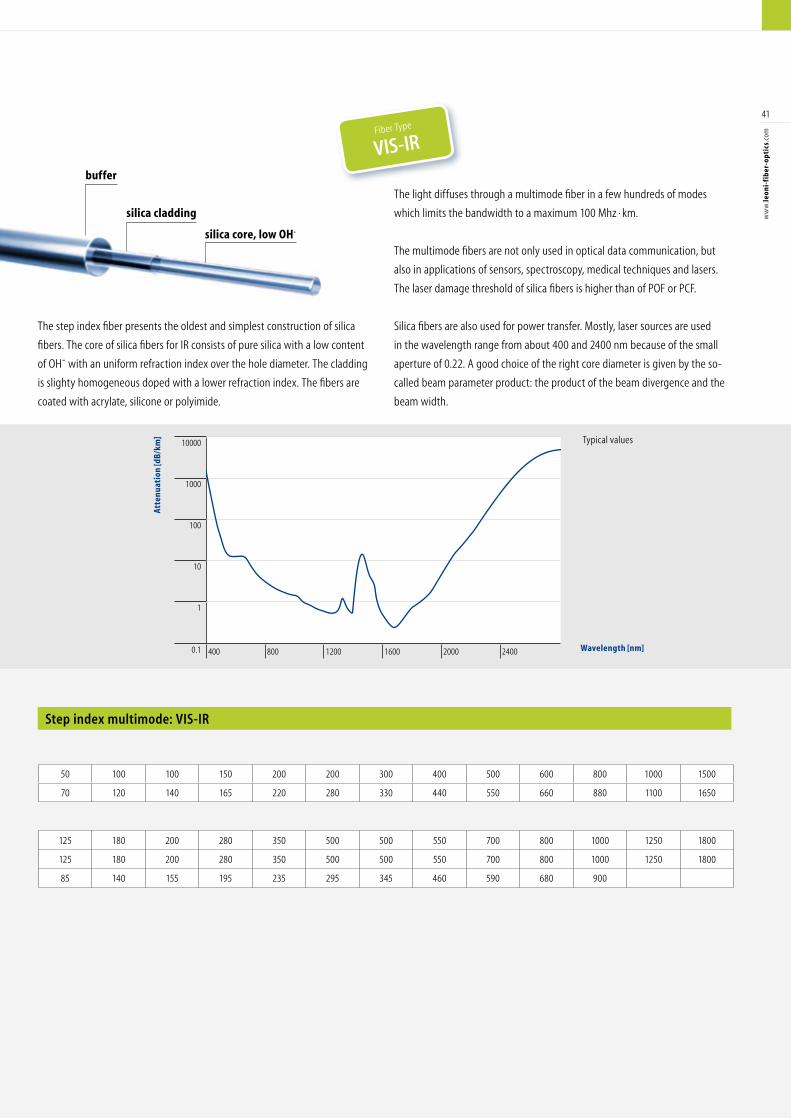
Step index multimode: VIS-IR
Typical values10000
1000
100
10
1
0.1 400 800 1200 1600 2000 2400
41
ww
w.le
oni-
fib
er-o
ptic
s.co
mGeometry: core and cladding
Core diameter [µm] 50 100 100 150 200 200 300 400 500 600 800 1000 1500 50 100 100 150 200 200 300 400 500 600 800 1000 1500
Cladding diameter [µm] 55 110 120 165 220 240 330 440 550 660 880 1100 1650 70 120 140 165 220 280 330 440 550 660 880 1100 1650
Geometry: buffer
Buffer diameter [µm] acrylate 125 180 200 280 350 450 500 550 700 800 1000 1250 1800 125 180 200 280 350 500 500 550 700 800 1000 1250 1800
Buffer diameter [µm] silicone 125 180 200 280 350 450 500 550 700 800 1000 1250 1800 125 180 200 280 350 500 500 550 700 800 1000 1250 1800
Buffer diameter [µm] polyimide 65 120 140 195 235 280 345 460 590 680 900 85 140 155 195 235 295 345 460 590 680 900
Atte
nuat
ion
[dB/
km]
Wavelength [nm]
silica core, low OH-
buffer
silica cladding
Fiber Type
VIS-IR
The light diffuses through a multimode fiber in a few hundreds of modes
which limits the bandwidth to a maximum 100 Mhz · km.
The multimode fibers are not only used in optical data communication, but
also in applications of sensors, spectroscopy, medical techniques and lasers.
The laser damage threshold of silica fibers is higher than of POF or PCF.
Silica fibers are also used for power transfer. Mostly, laser sources are used
in the wavelength range from about 400 and 2400 nm because of the small
aperture of 0.22. A good choice of the right core diameter is given by the so-
called beam parameter product: the product of the beam divergence and the
beam width.
The step index fiber presents the oldest and simplest construction of silica
fibers. The core of silica fibers for IR consists of pure silica with a low content
of OH¯ with an uniform refraction index over the hole diameter. The cladding
is slighty homogeneous doped with a lower refraction index. The fibers are
coated with acrylate, silicone or polyimide.
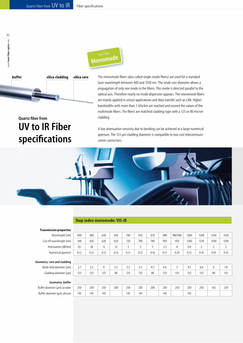
Fiber specifications
Step index monomode: VIS-IR
Quartz fiber from UV to IR
42
ww
w.le
oni-
fib
er-o
ptic
s.co
m
Transmission properties Transmission properties
Wavelength [nm] 400 480 630 630 780 810 810 980 980/1060 1300 1300 1550 1550 488 514 633 688 780 810 810 980 1064 1300 1300 1550 1550 Designed wavelength [nm]
Cut-off-wavelength [nm] 340 420 620 620 720 780 780 950 950 1260 1270 1500 1500 400 450 600 620 720 720 720 910 1000 1200 1200 1500 1500 Cut-off-wavelength [nm]
Attenuation [dB/km] 65 30 12 12 5 5 5 3.5 8 0.8 2 2 2 100 90 15 15 8 4 4 3 3 2 2 2 2 Attenuation [dB/km]
Numerical aperture 0.12 0.12 0.12 0.16 0.12 0.12 0.16 0.13 0.24 0.12 0.16 0.19 0.16 0.12 0.12 0.14 0.16 0.16 0.16 0.16 0.16 0.16 0.16 0.16 0.16 0.16 Numerical aperture
Geometry: core and cladding Geometry: core and cladding
Mode field diameter [µm] 2.7 3.2 4 3.3 5.5 5.5 4.3 6.6 3 9.5 6.6 6 7.8 3.6 3.6 3.2 3.2 3.6 4 4 4.2 6 6.6 6.6 7.9 7.9 Mode field diameter [µm]
Cladding diameter [µm] 125 125 125 80 125 125 80 125 125 125 125 80 125 125 125 125 125 125 125 80 125 125 125 80 125 80 Cladding diameter [µm]
Geometry: buffer Geometry: buffer
Buffer diameter [µm] acrylate 250 250 250 200 250 250 200 250 250 250 250 165 250 245 245 245 245 245 245 245 250 245 245 245 245 245 Buffer diameter [µm] 2xAcrylat
Buffer diameter [µm] silicone 145 145 145 145 145 145 145 400 400 400 400 400 400 400 400 400 400 400 400 400 Buffer diameter [µm] 2xAcrylat
Fiber Type
Monomode
buffer silica cladding silica core The monomode fibers (also called single-mode fibers) are used for a standard
laser wavelength between 400 and 1550 nm. The small core diameter allows a
propagation of only one mode in the fibers. This mode is directed parallel to the
optical axis. Therefore nearly no mode dispersion appears. The monomode fibers
are mainly applied in sensor applications and data transfer such as LAN. Higher
bandwidths with more than 1 GHz·km are reached and exceed the values of the
multimode fibers. The fibers are matched cladding type with a 125 or 80 micron
cladding.
A low attenuation sensivity due to bending can be achieved at a large numerical
aperture. The 125 µm cladding diameter is compatible to low cost telecommuni-
cation connectors.
Quartz fiber from
UV to IR Fiberspecifications
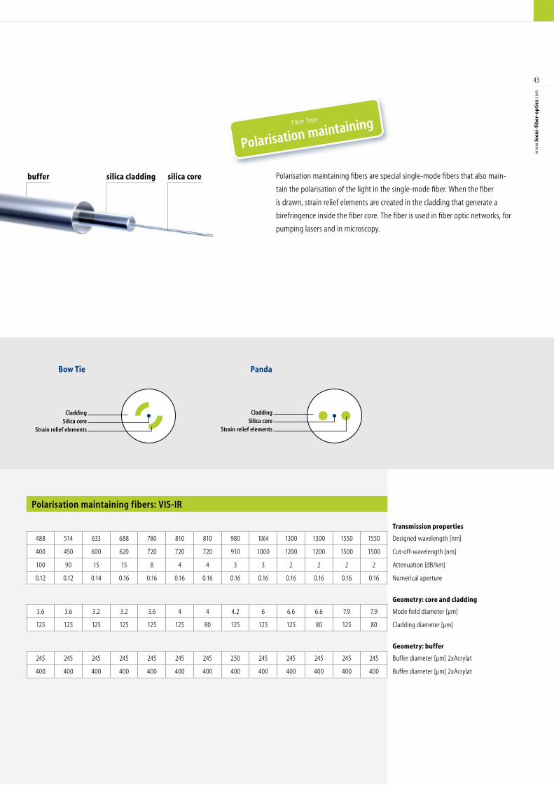
CladdingSilica core
Strain relief elements
Panda
CladdingSilica core
Strain relief elements
Bow Tie
Polarisation maintaining fibers: VIS-IR
43
ww
w.le
oni-
fib
er-o
ptic
s.co
m
Transmission properties Transmission properties
Wavelength [nm] 400 480 630 630 780 810 810 980 980/1060 1300 1300 1550 1550 488 514 633 688 780 810 810 980 1064 1300 1300 1550 1550 Designed wavelength [nm]
Cut-off-wavelength [nm] 340 420 620 620 720 780 780 950 950 1260 1270 1500 1500 400 450 600 620 720 720 720 910 1000 1200 1200 1500 1500 Cut-off-wavelength [nm]
Attenuation [dB/km] 65 30 12 12 5 5 5 3.5 8 0.8 2 2 2 100 90 15 15 8 4 4 3 3 2 2 2 2 Attenuation [dB/km]
Numerical aperture 0.12 0.12 0.12 0.16 0.12 0.12 0.16 0.13 0.24 0.12 0.16 0.19 0.16 0.12 0.12 0.14 0.16 0.16 0.16 0.16 0.16 0.16 0.16 0.16 0.16 0.16 Numerical aperture
Geometry: core and cladding Geometry: core and cladding
Mode field diameter [µm] 2.7 3.2 4 3.3 5.5 5.5 4.3 6.6 3 9.5 6.6 6 7.8 3.6 3.6 3.2 3.2 3.6 4 4 4.2 6 6.6 6.6 7.9 7.9 Mode field diameter [µm]
Cladding diameter [µm] 125 125 125 80 125 125 80 125 125 125 125 80 125 125 125 125 125 125 125 80 125 125 125 80 125 80 Cladding diameter [µm]
Geometry: buffer Geometry: buffer
Buffer diameter [µm] acrylate 250 250 250 200 250 250 200 250 250 250 250 165 250 245 245 245 245 245 245 245 250 245 245 245 245 245 Buffer diameter [µm] 2xAcrylat
Buffer diameter [µm] silicone 145 145 145 145 145 145 145 400 400 400 400 400 400 400 400 400 400 400 400 400 Buffer diameter [µm] 2xAcrylat
Polarisation maintaining fibers are special single-mode fibers that also main-
tain the polarisation of the light in the single-mode fiber. When the fiber
is drawn, strain relief elements are created in the cladding that generate a
birefringence inside the fiber core. The fiber is used in fiber optic networks, for
pumping lasers and in microscopy.
buffer silica cladding silica core
Fiber Type
Polarisation maintaining
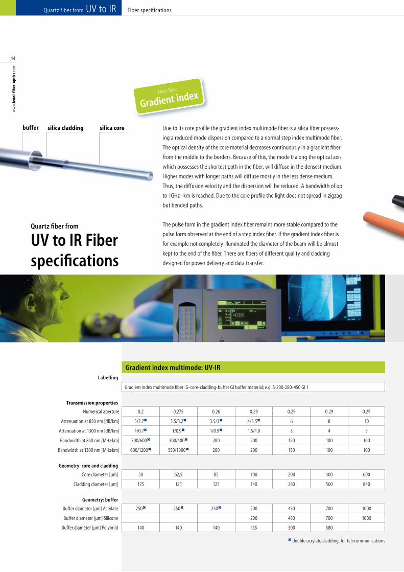
Fiber specifications
Gradient index multimode: UV-IR
Quartz fiber from UV to IR
44
ww
w.le
oni-
fib
er-o
ptic
s.co
m
Labelling
Gradient index multimode fiber: G-core-cladding-buffer GI buffer material; e.g. S-200-280-450 GI 1
Transmission properties
Numerical aperture 0.2 0.275 0.26 0.29 0.29 0.29 0.29
Attenuation at 850 nm [dB/km] 3/2.7 3.5/3.2 3.5/3 4/3.5 6 8 10
Attenuation at 1300 nm [dB/km] 1/0.7 1/0.9 1/0.9 1.5/1.0 3 4 5
Bandwidth at 850 nm [MHz·km] 300/600 300/400 200 200 150 100 100
Bandwidth at 1300 nm [MHz·km] 600/1200 550/1000 200 200 150 100 100
Geometry: core and cladding
Core diameter [µm] 50 62,5 85 100 200 400 600
Cladding diameter [µm] 125 125 125 140 280 560 840
Geometry: buffer
Buffer diameter [µm] Acrylate 250 250 250 200 450 700 1000
Buffer diameter [µm] Silicone 200 450 700 1000
Buffer diameter [µm] Polyimid 140 140 140 155 300 580
Fiber Type
Gradient index
double acrylate cladding, for telecommunications
Due to its core profile the gradient index multimode fiber is a silica fiber possess-
ing a reduced mode dispersion compared to a normal step index multimode fiber.
The optical density of the core material decreases continuously in a gradient fiber
from the middle to the borders. Because of this, the mode 0 along the optical axis
which possesses the shortest path in the fiber, will diffuse in the densest medium.
Higher modes with longer paths will diffuse mostly in the less dense medium.
Thus, the diffusion velocity and the dispersion will be reduced. A bandwidth of up
to 1GHz · km is reached. Due to the core profile the light does not spread in zigzag
but bended paths.
The pulse form in the gradient index fiber remains more stable compared to the
pulse form observed at the end of a step index fiber. If the gradient index fiber is
for example not completely illuminated the diameter of the beam will be almost
kept to the end of the fiber. There are fibers of different quality and cladding
designed for power delivery and data transfer.
buffer silica cladding silica core
Quartz fiber from
UV to IR Fiberspecifications
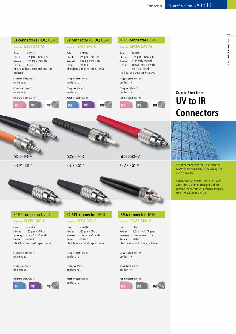
We offer connectors for UV-IR fibers to match all f iber diameters and a range of cable diameters. Connectors with metal ferrules are avail-able from 125 µm to 1000 µm, and we provide connectors with ceramic ferrules from 125 µm up to 600 µm.
Quartz fiber from UV to IRConnectors
45
ww
w.le
oni-
fib
er-o
ptic
s.co
m
FC PC connector UV-IR
Order No.: SFCPC-SK0-C
Color: metallic Fiber Ø: 125 µm – 600 µm Assembly: crimp/glue/polishFerrule: ceramicblack boot and dust cap inclusive
FC APC connector UV-IR
Order No.: SFCA-SK0-C
Color: metallic Fiber Ø: 125 µm – 600 µm Assembly: crimp/glue/polishFerrule: ceramicblack boot and dust cap inclusive
SMA connector UV-IR
Order No.: SSMA-SK0-M
Color: black Fiber Ø: 125 µm – 1500 µm Assembly: crimp/glue/polishFerrule: metalblack boot and dust cap inclusive
Stripping tool (Page 46)
on demand
Crimp tool (Page 47)
on demand
Polishing tool (Page 48)
Stripping tool (Page 46)
on demand
Crimp tool (Page 47)
on demand
Polishing tool (Page 48)
on demand
Stripping tool (Page 46)
on demand
Crimp tool (Page 47)
on demand
Polishing tool (Page 48)
SFCPC-SK0-MSXST-SK0-M SXST-SK0-C
FC PC connector UV-IR
Order No.: SFCPC-SK0-M
Color: metallic Fiber Ø: 125 µm – 1000 µm Assembly: crimp/glue/polishFerrule: metall, Ferrule with spring or fixed red boot and dust cap inclusive
Stripping tool (Page 46)
on demand
Crimp tool (Page 47)
on demand
Polishing tool (Page 48)
ST connector (BFOC) UV-IR
Order No.: SXST-SK0-M
Color: metallic Fiber Ø: 125 µm – 1000 µmAssembly: crimp/glue/polishFerrule: metalorange or black boot and dust cap inclusive
ST connector (BFOC) UV-IR
Order No.: SXST-SK0-C
Color: metallic Fiber Ø: 125 µm – 600 µm Assembly: crimp/glue/polish Ferrule: ceramic black boot and dust cap inclusive
Stripping tool (Page 46)
on demand
Crimp tool (Page 47)
on demand
Polishing tool (Page 48)
Stripping tool (Page 46)
on demand
Crimp tool (Page 47)
on demand
Polishing tool (Page 48)
SFCPC-SK0-C SFCA-SK0-C SSMA-SK0-M
Quartz fiber from
UV to IRConnectors
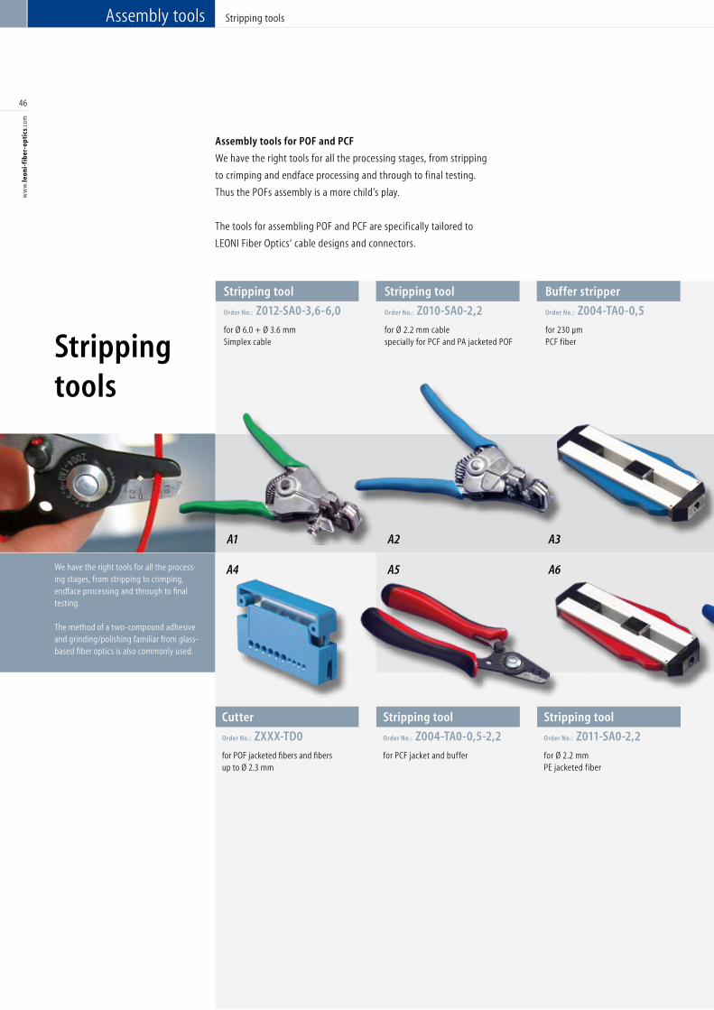
We have the right tools for all the process-ing stages, from stripping to crimping, endface processing and through to final testing. The method of a two-compound adhesive and grinding/polishing familiar from glass-based fiber optics is also commonly used.
46
ww
w.le
oni-
fib
er-o
ptic
s.co
m
Stripping tool
Order No.: Z004-TA0-0,5-2,2
for PCF jacket and buffer
Stripping tool
Order No.: Z011-SA0-2,2
for Ø 2.2 mm PE jacketed fiber
Assembly tools for POF and PCF
We have the right tools for all the processing stages, from stripping
to crimping and endface processing and through to final testing.
Thus the POFs assembly is a more child’s play.
The tools for assembling POF and PCF are specifically tailored to
LEONI Fiber Optics‘ cable designs and connectors.
Cutter
Order No.: ZXXX-TD0
for POF jacketed fibers and fibers up to Ø 2.3 mm
Stripping tools
Assembly tools Stripping tools
Stripping tool
Order No.: Z012-SA0-3,6-6,0
for Ø 6.0 + Ø 3.6 mm Simplex cable
Stripping tool
Order No.: Z010-SA0-2,2
for Ø 2.2 mm cable specially for PCF and PA jacketed POF
Buffer stripper
Order No.: Z004-TA0-0,5
for 230 µm PCF fiber
A1 A2 A3
A5 A6A4
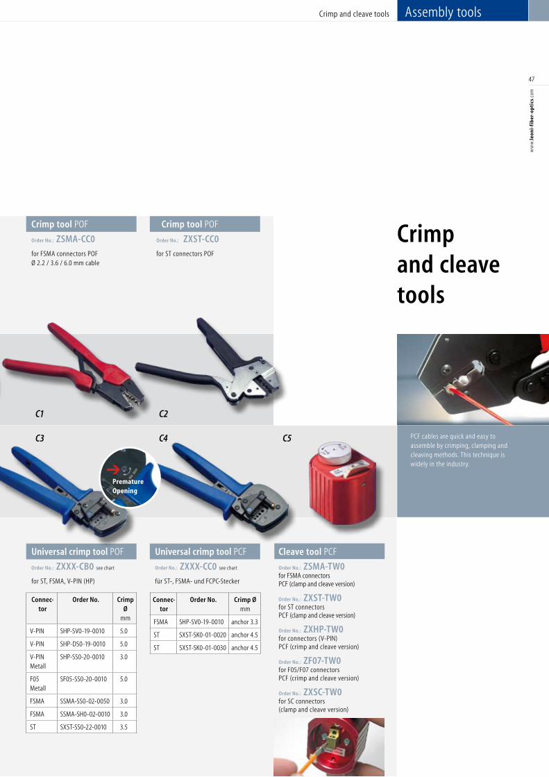
Assembly toolsCrimp and cleave tools
47
ww
w.le
oni-
fib
er-o
ptic
s.co
m
Connec-tor
Order No. Crimp Ø
mm
V-PIN SHP-SV0-19-0010 5.0
V-PIN SHP-DS0-19-0010 5.0
V-PIN Metall
SHP-SS0-20-0010 3.0
F05 Metall
SF05-SS0-20-0010 5.0
FSMA SSMA-SS0-02-0050 3.0
FSMA SSMA-SH0-02-0010 3.0
ST SXST-SS0-22-0010 3.5
Connec-tor
Order No. Crimp Ømm
FSMA SHP-SV0-19-0010 anchor 3.3
ST SXST-SK0-01-0020 anchor 4.5
ST SXST-SK0-01-0030 anchor 4.5
Crimp and cleave tools
C1
C3 C4 C5
Universal crimp tool POF
Order No.: ZXXX-CB0 see chart
for ST, FSMA, V-PIN (HP)
Universal crimp tool PCF
Order No.: ZXXX-CC0 see chart
für ST-, FSMA- und FCPC-Stecker
Cleave tool PCF
Order No.: ZSMA-TW0for FSMA connectors PCF (clamp and cleave version)
Order No.: ZXST-TW0 for ST connectors PCF (clamp and cleave version)
Order No.: ZXHP-TW0for connectors (V-PIN) PCF (crimp and cleave version)
Order No.: ZF07-TW0for F05/F07 connectors PCF (crimp and cleave version)
Order No.: ZXSC-TW0for SC connectors (clamp and cleave version)
Crimp tool POF
Order No.: ZXST-CC0
for ST connectors POF
PCF cables are quick and easy to assemble by crimping, clamping and cleaving methods. This technique is widely in the industry.
C2
Crimp tool POF
Order No.: ZSMA-CC0
for FSMA connectors POF Ø 2.2 / 3.6 / 6.0 mm cable
Premature Opening
➔
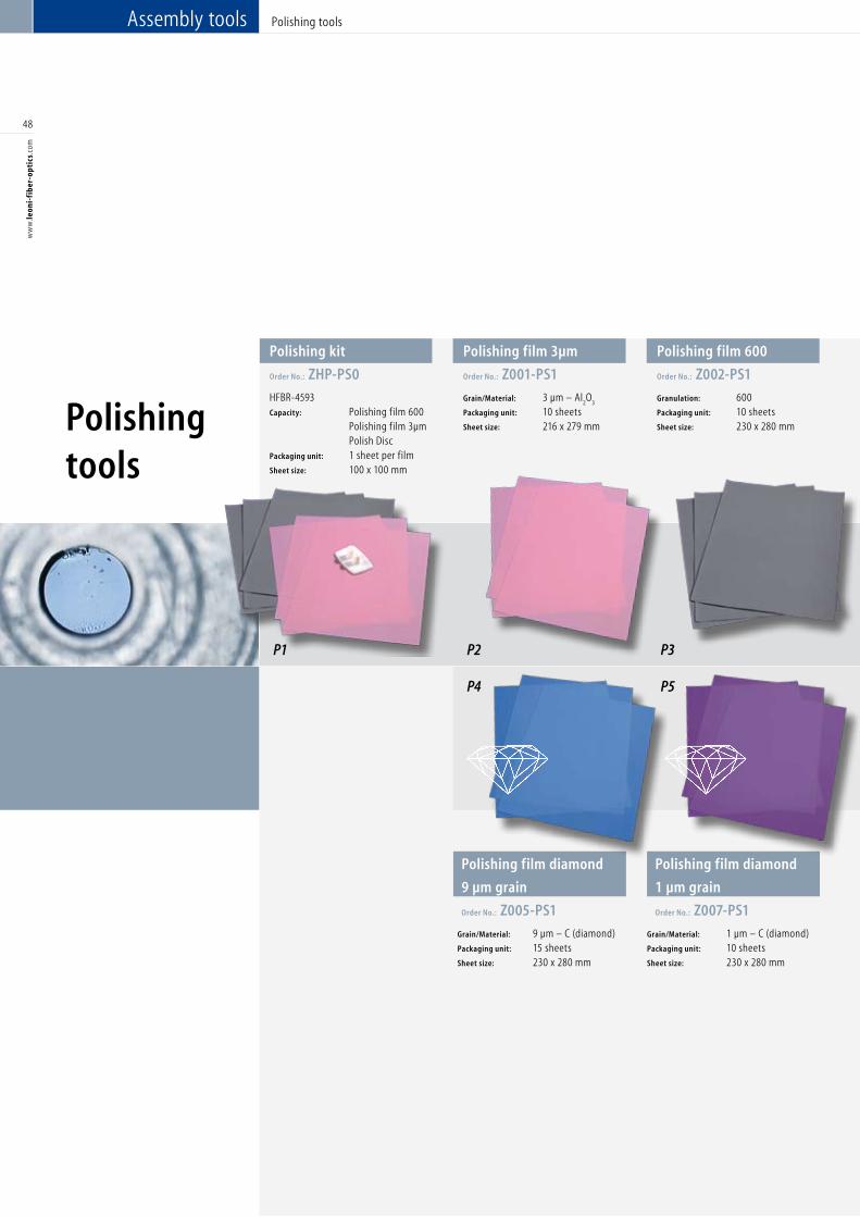
48
ww
w.le
oni-
fib
er-o
ptic
s.co
m
Polishing film diamond
9 µm grain
Order No.: Z005-PS1
Grain/Material: 9 µm – C (diamond)Packaging unit: 15 sheetsSheet size: 230 x 280 mm
Polishing film diamond
1 µm grain
Order No.: Z007-PS1
Grain/Material: 1 µm – C (diamond)Packaging unit: 10 sheetsSheet size: 230 x 280 mm
Polishingtools
Polishing tools
Polishing kit
Order No.: ZHP-PS0
HFBR-4593Capacity: Polishing film 600 Polishing film 3µm Polish Disc Packaging unit: 1 sheet per filmSheet size: 100 x 100 mm
Polishing film 3µm
Order No.: Z001-PS1
Grain/Material: 3 µm – Al2O
3
Packaging unit: 10 sheetsSheet size: 216 x 279 mm
Polishing film 600
Order No.: Z002-PS1
Granulation: 600 Packaging unit: 10 sheetsSheet size: 230 x 280 mm
P1 P2 P3
P4 P5
Assembly tools
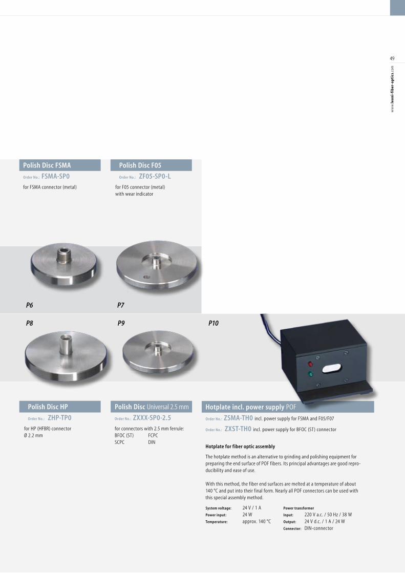
49
ww
w.le
oni-
fib
er-o
ptic
s.co
m
Hotplate incl. power supply POF
Order No.: ZSMA-TH0 incl. power supply for FSMA and F05/F07
Order No.: ZXST-TH0 incl. power supply for BFOC (ST) connector
Hotplate for fiber optic assembly
The hotplate method is an alternative to grinding and polishing equipment for preparing the end surface of POF fibers. Its principal advantages are good repro-ducibility and ease of use.
With this method, the fiber end surfaces are melted at a temperature of about 140 °C and put into their final form. Nearly all POF connectors can be used with this special assembly method.
System voltage: 24 V / 1 A Power transformer
Power input: 24 W Input: 220 V a.c. / 50 Hz / 38 W Temperature: approx. 140 °C Output: 24 V d.c. / 1 A / 24 W Connector: DIN-connector
P6
P9 P10
Polish Disc Universal 2.5 mm
Order No.: ZXXX-SP0-2.5
for connectors with 2.5 mm ferrule: BFOC (ST) FCPC SCPC DIN
Polish Disc F05
Order No.: ZF05-SP0-L
for F05 connector (metal) with wear indicator
P7
Polish Disc FSMA
Order No.: FSMA-SP0
for FSMA connector (metal)
Polish Disc HP
Order No.: ZHP-TP0
for HP (HFBR) connector Ø 2.2 mm
P8
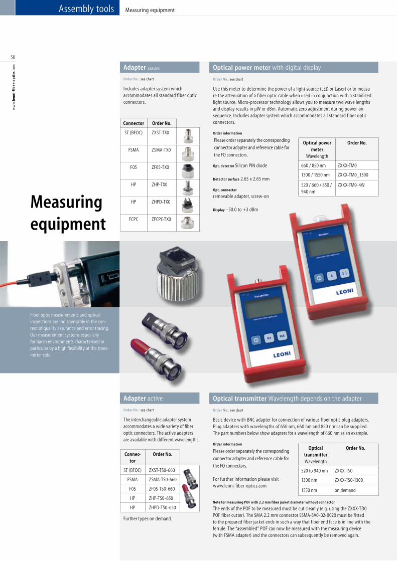
50
ww
w.le
oni-
fib
er-o
ptic
s.co
m
Measuring equipment
Fiber optic measurements and optical inspections are indispensable in the con-text of quality assurance and error tracing. Our measurement systems especially for harsh environments characterised in particular by a high flexibility at the trans-mitter side.
Measuring equipment
Adapter passive
Order No.: see chart
Includes adapter system which accommodates all standard fiber optic connectors.
Optical power meter with digital display
Order No.: see chart
Use this meter to determine the power of a light source (LED or Laser) or to measu-re the attenuation of a fiber optic cable when used in conjunction with a stabilized light source. Micro-processor technology allows you to measure two wave lengths and display results in µW or dBm. Automatic zero adjustment during power-on sequence. Includes adapter system which accommodates all standard fiber optic connectors.
Order information
Please order separately the corresponding
connector adapter and reference cable for
the FO connectors.
Opt. detector Silicon PIN diode
Detector surface 2.65 x 2.65 mm
Opt. connector
removable adapter, screw-on
Display –50.0 to +3 dBm
Connector Order No.
ST (BFOC) ZXST-TX0
FSMA ZSMA-TX0
F05 ZF05-TX0
HP ZHP-TX0
HP ZHPD-TX0
FCPC ZFCPC-TX0
Optical power meter
Wavelength
Order No.
660 / 850 nm ZXXX-TM0
1300 / 1550 nm ZXXX-TM0_1300
520 / 660 / 850 / 940 nm
ZXXX-TM0-4W
Adapter active
Order No.: see chart
The interchangeable adapter system accommodates a wide variety of fiber optic connectors. The active adapters are available with different wavelengths.
Connec-tor
Order No.
ST (BFOC) ZXST-TS0-660
FSMA ZSMA-TS0-660
F05 ZF05-TS0-660
HP ZHP-TS0-650
HP ZHPD-TS0-650
Optical transmitter Wavelength depends on the adapter
Order No.: see chart
Basic device with BNC adapter for connection of various fiber optic plug adapters. Plug adapters with wavelengths of 650 nm, 660 nm and 850 nm can be supplied. The part numbers below show adapters for a wavelength of 660 nm as an example.
Order information
Please order separately the corresponding
connector adapter and reference cable for
the FO connectors. For further information please visit www.leoni-fiber-optics.com
Further types on demand.
Note for measuring POF with 2.2 mm fiber jacket diameter without connector
The ends of the POF to be measured must be cut cleanly (e.g. using the ZXXX-TD0 POF fiber cutter). The SMA 2.2 mm connector SSMA-SV0-02-0020 must be fitted to the prepared fiber jacket ends in such a way that fiber end face is in line with the ferrule. The “assembled“ POF can now be measured with the measuring device (with FSMA adapter) and the connectors can subsequently be removed again.
Assembly tools
Optical transmitter Wavelength
Order No.
520 to 940 nm ZXXX-TS0
1300 nm ZXXX-TS0-1300
1550 nm on demand
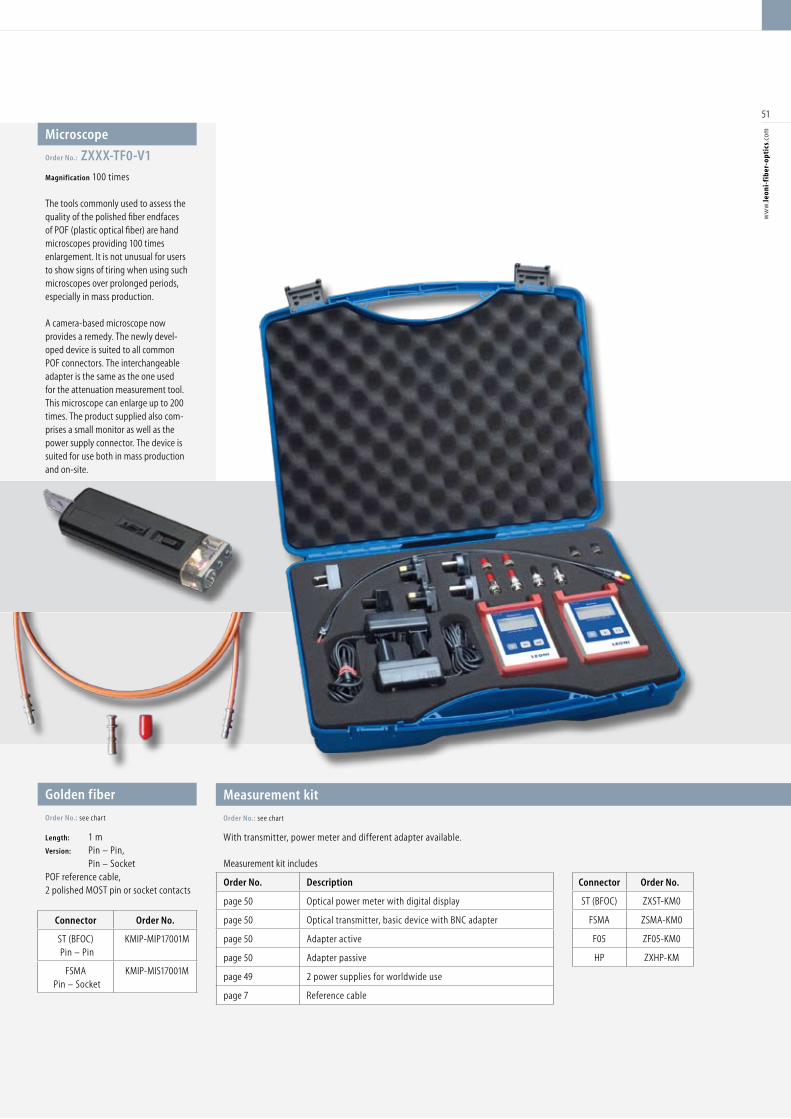
51
ww
w.le
oni-
fib
er-o
ptic
s.co
m
Measurement kit
Order No.: see chart
With transmitter, power meter and different adapter available.
Golden fiber
Order No.: see chart
Length: 1 m Version: Pin – Pin, Pin – Socket POF reference cable,2 polished MOST pin or socket contacts
Connector Order No.
ST (BFOC)Pin – Pin
KMIP-MIP17001M
FSMAPin – Socket
KMIP-MIS17001M
Connector Order No.
ST (BFOC) ZXST-KM0
FSMA ZSMA-KM0
F05 ZF05-KM0
HP ZXHP-KM
Microscope
Order No.: ZXXX-TF0-V1
Magnification 100 times The tools commonly used to assess thequality of the polished fiber endfaces of POF (plastic optical fiber) are hand microscopes providing 100 times enlargement. It is not unusual for users to show signs of tiring when using such microscopes over prolonged periods, especially in mass production.
A camera-based microscope now provides a remedy. The newly devel-oped device is suited to all common POF connectors. The interchangeable adapter is the same as the one used for the attenuation measurement tool. This microscope can enlarge up to 200 times. The product supplied also com-prises a small monitor as well as the power supply connector. The device is suited for use both in mass production and on-site.
Measurement kit includes
Order No. Description
page 50 Optical power meter with digital display
page 50 Optical transmitter, basic device with BNC adapter
page 50 Adapter active
page 50 Adapter passive
page 49 2 power supplies for worldwide use
page 7 Reference cable
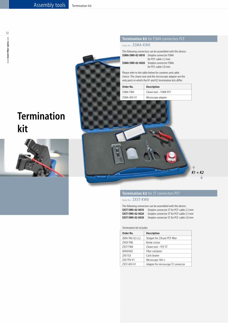
52
ww
w.le
oni-
fib
er-o
ptic
s.co
m Termination kit for FSMA connectors PCF
Order No.: ZSMA-KW0
The following connectors can be assembled with this device:SSMA-SW0-02-0010 Simplex connector FSMA for PCF-cable 2.2 mm SSMA-SW0-02-0020 Simplex connector FSMA for PCF-cable 3.0 mm
Termination kit
Termination kit
Assembly tools
Please refer to the table below for contents and cable choice. The cleave tool and the microscope adapter are the only parts in which the K1 and K2 termination kits differ.
Order No. Description
ZSMA-TW0 Cleave tool – FSMA PCF
ZSMA-AF0-V1 Microscope adapter
Termination kit includes
Order No. Description
Z004-TA0-0,5-2,2 Stripper for 230 µm PCF-fiber
ZXXX-TN0 Kevlar scissor
ZXST-TW0 Cleave tool – PCF ST
00405402 Fiber container
ZXX-TL0 Card cleaner
ZXX-TF0-V1 Microscope 100 ×
ZXST-AF0-V1 Adapter for microscope ST connector
Termination kit for ST connectors PCF
Order No.: ZXST-KW0
The following connectors can be assembled with this device:SXST-SW0-02-0010 Simplex connector ST for PCF-cable 2.2 mmSXST-SW0-02-0020 Simplex connector ST for PCF-cable 2.5 mmSXST-SW0-02-0030 Simplex connector ST for PCF-cable 3.0 mm
K1 + K2
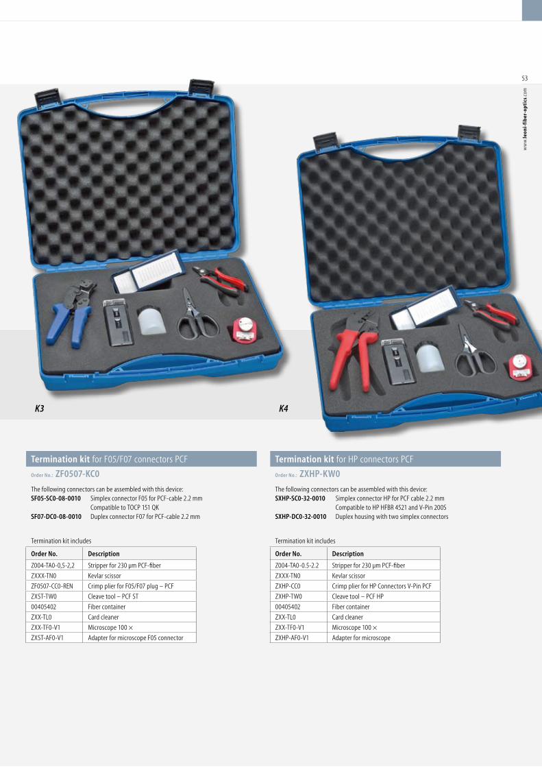
K3 K4
53
ww
w.le
oni-
fib
er-o
ptic
s.co
m
Termination kit for F05/F07 connectors PCF
Order No.: ZF0507-KC0
The following connectors can be assembled with this device: SF05-SC0-08-0010 Simplex connector F05 for PCF-cable 2.2 mm Compatible to TOCP 151 QKSF07-DC0-08-0010 Duplex connector F07 for PCF-cable 2.2 mm
Termination kit for HP connectors PCF
Order No.: ZXHP-KW0
The following connectors can be assembled with this device: SXHP-SC0-32-0010 Simplex connector HP for PCF cable 2.2 mm Compatible to HP HFBR 4521 and V-Pin 200SSXHP-DC0-32-0010 Duplex housing with two simplex connectors
Termination kit includes
Order No. Description
Z004-TA0-0,5-2,2 Stripper for 230 µm PCF-fiber
ZXXX-TN0 Kevlar scissor
ZF0507-CC0-REN Crimp plier for F05/F07 plug – PCF
ZXST-TW0 Cleave tool – PCF ST
00405402 Fiber container
ZXX-TL0 Card cleaner
ZXX-TF0-V1 Microscope 100 ×
ZXST-AF0-V1 Adapter for microscope F05 connector
Termination kit includes
Order No. Description
Z004-TA0-0.5-2.2 Stripper for 230 µm PCF-fiber
ZXXX-TN0 Kevlar scissor
ZXHP-CC0 Crimp plier for HP Connectors V-Pin PCF
ZXHP-TW0 Cleave tool – PCF HP
00405402 Fiber container
ZXX-TL0 Card cleaner
ZXX-TF0-V1 Microscope 100 ×
ZXHP-AF0-V1 Adapter for microscope

LEONI service
It is also always worth having a look
at our website:
www.leoni-fiber-optics.com
54
ww
w.le
oni-
fib
er-o
ptic
s.co
mLEONI service | LEONI also produces…LEONI
We have the latest information for you.
Our up-to-date information services including LEONIinfoLine
or LEONIinfoMail provide current information by post or
e-mail about the latest developments at LEONI Fiber Optics
and in the market, and will also inform you on important
dates and events.
In response to customer enquiries, we set up a team at the beginning
of 2004 to handle on-site service and repair of fiber optic cables of all
kinds. The team has already handled numerous service oders world-
wide.
Working together with our service team provides major benefits for
both parties. Our service person has the necessary expertise to help
quickly and immediately. In addition, he can respond specifically to
customer requirements and suggest solutions. In return, we welcome
receiving ideas and suggestions on-site to improve our products.
In the process, our service frequently also goes beyond matters relat-
ing to our products. When needed, we also provide on-site problem
analyses and suggest solutions with respect to the active components.
We shall be pleased to be at your disposal also for installa-
tion projects or repair jobs.
Do you have any questions in this regard?
Then please contact
Bernd Froetschner
Phone +49 (0)36764-81-427
Fax +49 (0)36764-81-110
E-mail [email protected]
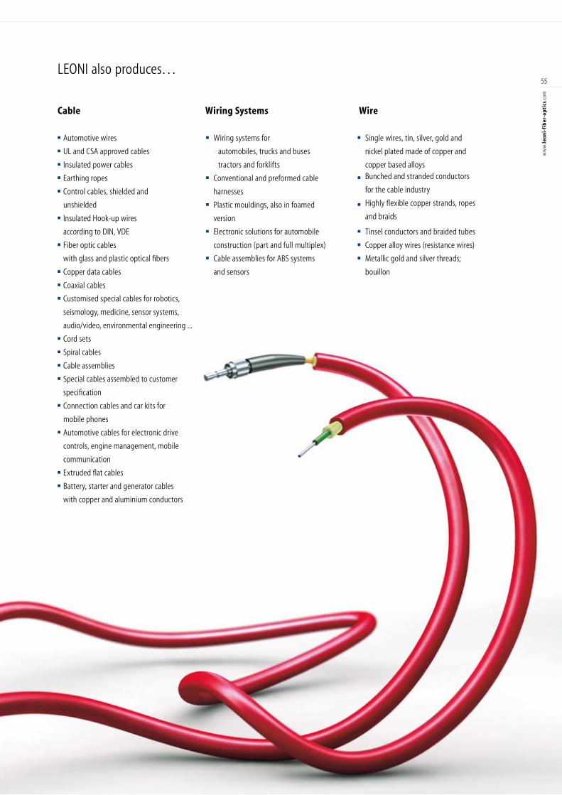
LEONI also produces…
■ Single wires, tin, silver, gold and
nickel plated made of copper and
copper based alloys■ Bunched and stranded conductors
for the cable industry
■ Highly flexible copper strands, ropes
and braids
■ Tinsel conductors and braided tubes■ Copper alloy wires (resistance wires)■ Metallic gold and silver threads;
bouillon
■ Wiring systems for
■ automobiles, trucks and buses
■ tractors and forklifts ■ Conventional and preformed cable
harnesses ■ Plastic mouldings, also in foamed
version■ Electronic solutions for automobile
construction (part and full multiplex)■ Cable assemblies for ABS systems
and sensors
■ Automotive wires ■ UL and CSA approved cables■ Insulated power cables■ Earthing ropes ■ Control cables, shielded and
unshielded ■ Insulated Hook-up wires
according to DIN, VDE■ Fiber optic cables
with glass and plastic optical fibers ■ Copper data cables■ Coaxial cables ■ Customised special cables for robotics,
seismology, medicine, sensor systems,
audio/video, environmental engineering ...■ Cord sets■ Spiral cables■ Cable assemblies■ Special cables assembled to customer
specification■ Connection cables and car kits for
mobile phones■ Automotive cables for electronic drive
controls, engine management, mobile
communication■ Extruded flat cables■ Battery, starter and generator cables
with copper and aluminium conductors
Cable Wiring Systems Wire
55
ww
w.le
oni-
fib
er-o
ptic
s.co
m

LEONI Fiber Optics
GmbH
Muehldamm 6
96524 Neuhaus-Schierschnitz
Germany
Phone +49 (0)36764-81100
Fax +49 (0)36764-81110
E-mail [email protected]
www.leoni-fiber-optics.com
Recommended