
ffirs.indd 2 12/31/2015 7:31:48 PM
Complete Electronics
Book Author ffirs V1 December 28, 2015 6:43 PM
ffirs.indd 1 12/31/2015 7:31:48 PM

ffirs.indd 2 12/31/2015 7:31:48 PM
Complete Electronics
S E L F - T E A C H I N G G U I D E W I T H P R O J E C T S
Earl Boysen | Harry Kybett
Book Author ffirs V1 December 28, 2015 6:43 PM
ffirs.indd 3 12/31/2015 7:31:49 PM

Complete Electronics
Executive Editor: Carol LongProject Editor: Kevin ShaferTechnical Editor: Rex MillerProduction Editor: Kathleen WisorCopy Editor: San Dee PhillipsEditorial Manager: Mary Beth Wakefield Freelancer Editorial Manager: Rosemarie GrahamAssociate Director of Marketing: David MayhewMarketing Manager: Ashley ZurcherBusiness Manager: Amy KniesProduction Manager: Tim TateVice President and Executive Group Publisher: Richard SwadleyVice President and Executive Publisher: Neil EddeAssociate Publisher: Jim MinatelProject Coordinator, Cover: Katie CrockerProofreader: Nancy CarrascoIndexer: Jack LewisCover Image: © Bart Coenders / iStockPhotoCover Designer: Ryan Sneed
Published by John Wiley & Sons, Inc. 10475 Crosspoint Boulevard Indianapolis, IN 46256 www.wiley.com
Copyright © 2012 by Earl Boysen and Harry Kybett
Published by John Wiley & Sons, Inc., Indianapolis, Indiana
Published simultaneously in Canada
ISBN: 978-1-118-21732-0 ISBN: 978-1-118-28232-8 (ebk) ISBN: 978-1-118-28319-6 (ebk) ISBN: 978-1-118-28469-8 (ebk)
Manufactured in the United States of America
10 9 8 7 6 5 4 3 2 1
No part of this publication may be reproduced, stored in a retrieval system or transmitted in any form or by any means, electronic, mechanical, photocopying, recording, scanning or otherwise, except as permitted under Sections 107 or 108 of the 1976 United States Copyright Act, without either the prior written permission of the Publisher, or authorization through payment of the appropriate per-copy fee to the Copyright Clearance Center, 222 Rosewood Drive, Danvers, MA 01923, (978) 750-8400, fax (978) 646-8600. Requests to the Publisher for permission should be addressed to the Permissions Department, John Wiley & Sons, Inc., 111 River Street, Hobo-ken, NJ 07030, (201) 748-6011, fax (201) 748-6008, or online at http://www.wiley.com/go/permissions.
Limit of Liability/Disclaimer of Warranty: The publisher and the author make no representations or warranties with respect to the accuracy or completeness of the contents of this work and specifically disclaim all warranties, including without limitation warran-ties of fitness for a particular purpose. No warranty may be created or extended by sales or promotional materials. The advice and strategies contained herein may not be suitable for every situation. This work is sold with the understanding that the publisher is not engaged in rendering legal, accounting, or other professional services. If professional assistance is required, the services of a com-petent professional person should be sought. Neither the publisher nor the author shall be liable for damages arising herefrom. The fact that an organization or Web site is referred to in this work as a citation and/or a potential source of further information does not mean that the author or the publisher endorses the information the organization or website may provide or recommendations it may make. Further, readers should be aware that Internet websites listed in this work may have changed or disappeared between when this work was written and when it is read.
For general information on our other products and services please contact our Customer Care Department within the United States at (877) 762-2974, outside the United States at (317) 572-3993 or fax (317) 572-4002.
Wiley publishes in a variety of print and electronic formats and by print-on-demand. Some material included with standard print versions of this book may not be included in e-books or in print-on-demand. If this book refers to media such as a CD or DVD that is not included in the version you purchased, you may download this material at http://booksupport .wiley.com. For more information about Wiley products, visit www.wiley.com.
Library of Congress Control Number: 2012940030
Trademarks: Wiley and the Wiley logo are trademarks or registered trademarks of John Wiley & Sons, Inc. and/or its affiliates, in the United States and other countries, and may not be used without written permission. All other trademarks are the property of their respective owners. John Wiley & Sons, Inc. is not associated with any product or vendor mentioned in this book.
Book Author ffirs V1 December 28, 2015 6:43 PM
ffirs.indd 4 12/31/2015 7:31:49 PM
To my science and engineering teachers. I’d particularly like to
thank Jim Giovando, my physics and chemistry teacher at
Petaluma Senior High School, who, even decades later, I
remember as having been an inspiration. I also dedicate this
book to the physics and chemistry faculty of Sonoma State
University in the 1970s, where the small class size and personal
guidance by the professors made for a great learning
environment.
Book Author ffirs V1 December 28, 2015 6:43 PM
ffirs.indd 5 12/31/2015 7:31:49 PM
vi
About the Author
Earl Boysen spent 20 years as an engineer in the semiconductor industry, and
currently runs two websites, BuildingGadgets.com (dedicated to electronics) and
UnderstandingNano.com (covering nanotechnology topics). Boysen holds a Masters
degree in Engineering Physics from the University of Virginia. He is the co-author of
three other books: Electronics Projects For Dummies (Indianapolis: Wiley, 2006), Nano-
technology For Dummies (Indianapolis: Wiley, 2011), and the first edition of Electronics
For Dummies (Indianapolis: Wiley, 2005). He lives with his wonderful wife, Nancy, and
two cats.
Book Author ffirs V1 December 28, 2015 6:43 PM
ffirs.indd 6 12/31/2015 7:31:50 PM
vii
About the Technical Editor
Rex Miller was a Professor of Industrial Technology at The State University of New
York, College at Buffalo for more than 35 years. He has taught on the technical school,
high school, and college level for more than 40 years. He is the author or co-author of
more than 100 textbooks ranging from electronics through carpentry and sheet metal
work. He has contributed more than 50 magazine articles over the years to technical
publications. He is also the author of seven civil war regimental histories.
Book Author ffirs V1 December 28, 2015 6:43 PM
ffirs.indd 7 12/31/2015 7:31:51 PM
viii
Acknowledgments
I want to first thank Harry Kybett for authoring the original version of
this book many years ago. It’s an honor to take over such a classic book in the electronics
field. Thanks also to Carol Long for bringing me on board with the project, and Kevin
Shafer for his able project management of the book. My appreciation to Rex Miller for
his excellent technical editing, and to San Dee Phillips for handling all the mechanics
of spelling and grammar in a thorough copy edit. Finally, thanks to my wonderful wife,
Nancy, for her advice and support throughout the writing of this book.
Book Author ffirs V1 December 28, 2015 6:43 PM
ffirs.indd 8 12/31/2015 7:31:51 PM
ix
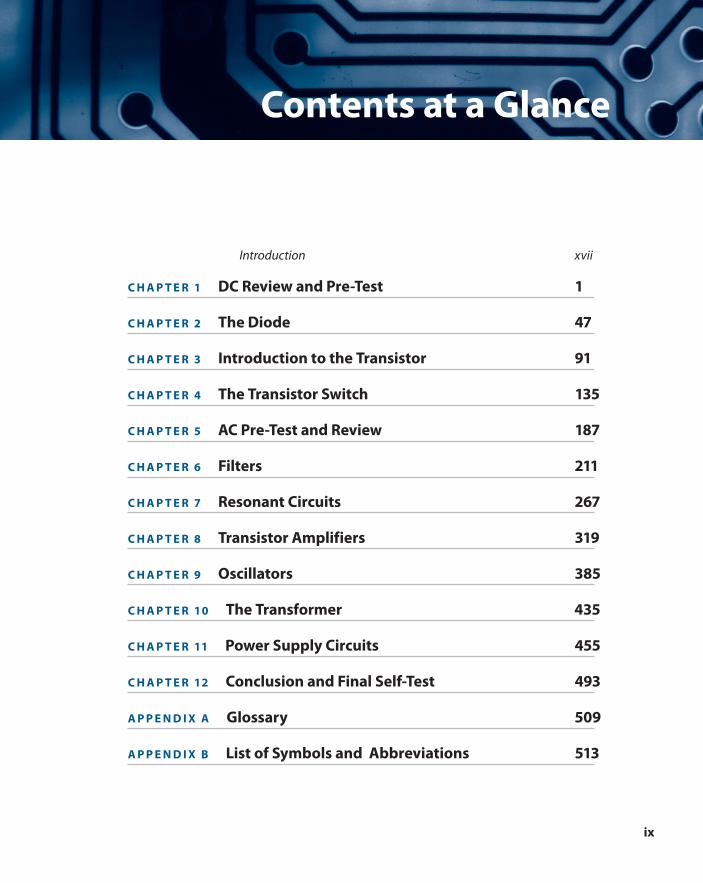
Contents at a Glance
Introduction xvii
C H A P T E R 1 DC Review and Pre-Test 1
C H A P T E R 2 The Diode 47
C H A P T E R 3 Introduction to the Transistor 91
C H A P T E R 4 The Transistor Switch 135
C H A P T E R 5 AC Pre-Test and Review 187
C H A P T E R 6 Filters 211
C H A P T E R 7 Resonant Circuits 267
C H A P T E R 8 Transistor Amplifiers 319
C H A P T E R 9 Oscillators 385
C H A P T E R 10 The Transformer 435
C H A P T E R 11 Power Supply Circuits 455
C H A P T E R 12 Conclusion and Final Self-Test 493
A P P E N D I X A Glossary 509
A P P E N D I X B List of Symbols and Abbreviations 513
Book Author ffirs V1 December 28, 2015 6:43 PM
ffirs.indd 9 12/31/2015 7:31:51 PM
x
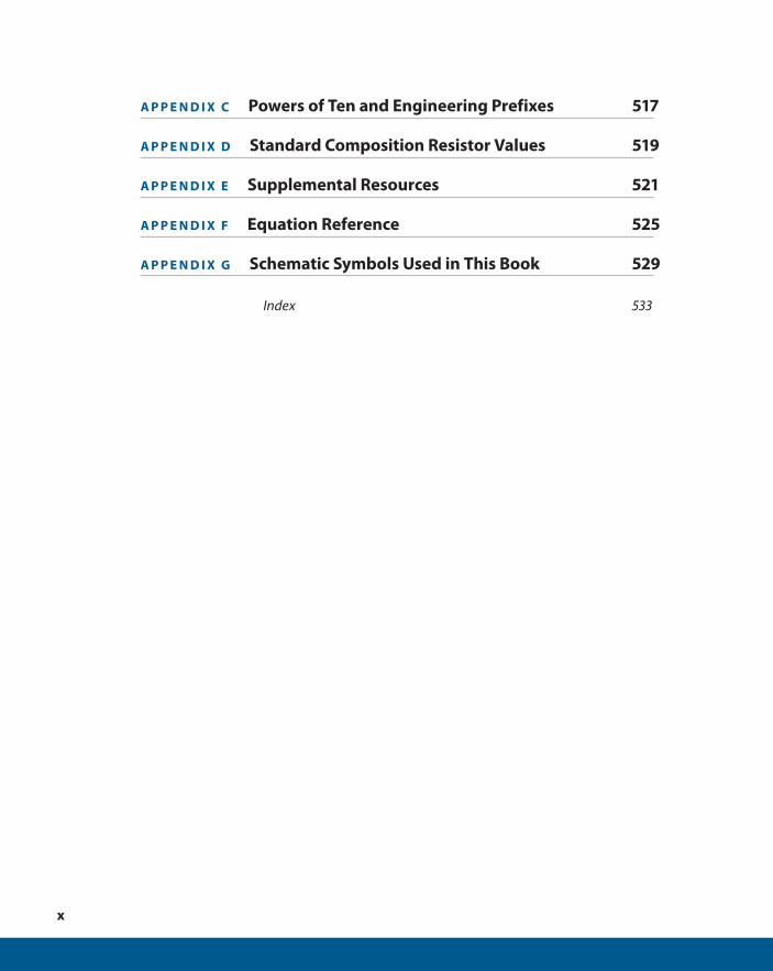
A P P E N D I X C Powers of Ten and Engineering Prefixes 517
A P P E N D I X D Standard Composition Resistor Values 519
A P P E N D I X E Supplemental Resources 521
A P P E N D I X F Equation Reference 525
A P P E N D I X G Schematic Symbols Used in This Book 529
Index 533
Book Author ffirs V1 December 28, 2015 6:43 PM
ffirs.indd 10 12/31/2015 7:31:51 PM
xi
Contents
Introduction xvii
C H A P T E R 1 DC Review and Pre-Test 1
Current Flow . . . . . . . . . . . . . . . . . . . . . . . . . . . . . . . . . . . . . . . . . . . . . . . 2
Ohm’s Law . . . . . . . . . . . . . . . . . . . . . . . . . . . . . . . . . . . . . . . . . . . . . . . . . 5
Resistors in Series . . . . . . . . . . . . . . . . . . . . . . . . . . . . . . . . . . . . . . . . . . 10
Resistors in Parallel . . . . . . . . . . . . . . . . . . . . . . . . . . . . . . . . . . . . . . . . . 10
Power. . . . . . . . . . . . . . . . . . . . . . . . . . . . . . . . . . . . . . . . . . . . . . . . . . . . . . 12
Small Currents . . . . . . . . . . . . . . . . . . . . . . . . . . . . . . . . . . . . . . . . . . . . . 15
The Graph of Resistance . . . . . . . . . . . . . . . . . . . . . . . . . . . . . . . . . . . . 16
The Voltage Divider . . . . . . . . . . . . . . . . . . . . . . . . . . . . . . . . . . . . . . . . 18
The Current Divider . . . . . . . . . . . . . . . . . . . . . . . . . . . . . . . . . . . . . . . . 24
Switches . . . . . . . . . . . . . . . . . . . . . . . . . . . . . . . . . . . . . . . . . . . . . . . . . . . 30
Capacitors in a DC Circuit . . . . . . . . . . . . . . . . . . . . . . . . . . . . . . . . . . . 33
Summary . . . . . . . . . . . . . . . . . . . . . . . . . . . . . . . . . . . . . . . . . . . . . . . . . . 41
DC Pre-Test . . . . . . . . . . . . . . . . . . . . . . . . . . . . . . . . . . . . . . . . . . . . . . . . 43
C H A P T E R 2 The Diode 47
Understanding Diodes . . . . . . . . . . . . . . . . . . . . . . . . . . . . . . . . . . . . . 48
Diode Breakdown . . . . . . . . . . . . . . . . . . . . . . . . . . . . . . . . . . . . . . . . . . 70
The Zener Diode . . . . . . . . . . . . . . . . . . . . . . . . . . . . . . . . . . . . . . . . . . . 75
Summary . . . . . . . . . . . . . . . . . . . . . . . . . . . . . . . . . . . . . . . . . . . . . . . . . . 86
Self-Test. . . . . . . . . . . . . . . . . . . . . . . . . . . . . . . . . . . . . . . . . . . . . . . . . . . . 87
Book Author ftoc V1 December 28, 2015 6:44 PM
ftoc.indd 11 12/31/2015 7:32:17 PM
xii
C H A P T E R 3 Introduction to the Transistor 91
Understanding Transistors . . . . . . . . . . . . . . . . . . . . . . . . . . . . . . . . . . 92
The Junction Field Effect Transistor (JFET) . . . . . . . . . . . . . . . . . . . 123
Summary . . . . . . . . . . . . . . . . . . . . . . . . . . . . . . . . . . . . . . . . . . . . . . . . . . 129
Self-Test. . . . . . . . . . . . . . . . . . . . . . . . . . . . . . . . . . . . . . . . . . . . . . . . . . . . 129
C H A P T E R 4 The Transistor Switch 135
Turning the Transistor On . . . . . . . . . . . . . . . . . . . . . . . . . . . . . . . . . . . 136
Turning Off the Transistor . . . . . . . . . . . . . . . . . . . . . . . . . . . . . . . . . . 142
Why Transistors Are Used as Switches . . . . . . . . . . . . . . . . . . . . . . . 146
The Three-Transistor Switch . . . . . . . . . . . . . . . . . . . . . . . . . . . . . . . . 161
Alternative Base Switching . . . . . . . . . . . . . . . . . . . . . . . . . . . . . . . . . 166
Switching the JFET . . . . . . . . . . . . . . . . . . . . . . . . . . . . . . . . . . . . . . . . . 172
Summary . . . . . . . . . . . . . . . . . . . . . . . . . . . . . . . . . . . . . . . . . . . . . . . . . . 181
Self-Test. . . . . . . . . . . . . . . . . . . . . . . . . . . . . . . . . . . . . . . . . . . . . . . . . . . . 182
C H A P T E R 5 AC Pre-Test and Review 187
The Generator . . . . . . . . . . . . . . . . . . . . . . . . . . . . . . . . . . . . . . . . . . . . . 188
Resistors in AC Circuits. . . . . . . . . . . . . . . . . . . . . . . . . . . . . . . . . . . . . . 193
Capacitors in AC Circuits . . . . . . . . . . . . . . . . . . . . . . . . . . . . . . . . . . . . 195
The Inductor in an AC Circuit. . . . . . . . . . . . . . . . . . . . . . . . . . . . . . . . 202
Resonance . . . . . . . . . . . . . . . . . . . . . . . . . . . . . . . . . . . . . . . . . . . . . . . . . 204
Summary . . . . . . . . . . . . . . . . . . . . . . . . . . . . . . . . . . . . . . . . . . . . . . . . . . 207
Self-Test. . . . . . . . . . . . . . . . . . . . . . . . . . . . . . . . . . . . . . . . . . . . . . . . . . . . 207
C H A P T E R 6 Filters 211
Capacitors in AC Circuits . . . . . . . . . . . . . . . . . . . . . . . . . . . . . . . . . . . . 212
Capacitors and Resistors in Series . . . . . . . . . . . . . . . . . . . . . . . . . . . 214
Phase Shift of an RC Circuit . . . . . . . . . . . . . . . . . . . . . . . . . . . . . . . . . 239
Resistor and Capacitor in Parallel . . . . . . . . . . . . . . . . . . . . . . . . . . . . 246
Inductors in AC Circuits . . . . . . . . . . . . . . . . . . . . . . . . . . . . . . . . . . . . . 250
Book Author ftoc V1 December 28, 2015 6:44 PM
ftoc.indd 12 12/31/2015 7:32:18 PM
xiii
Phase Shift for an RL Circuit . . . . . . . . . . . . . . . . . . . . . . . . . . . . . . . . . 258
Summary . . . . . . . . . . . . . . . . . . . . . . . . . . . . . . . . . . . . . . . . . . . . . . . . . . 260
Self-Test. . . . . . . . . . . . . . . . . . . . . . . . . . . . . . . . . . . . . . . . . . . . . . . . . . . . 260
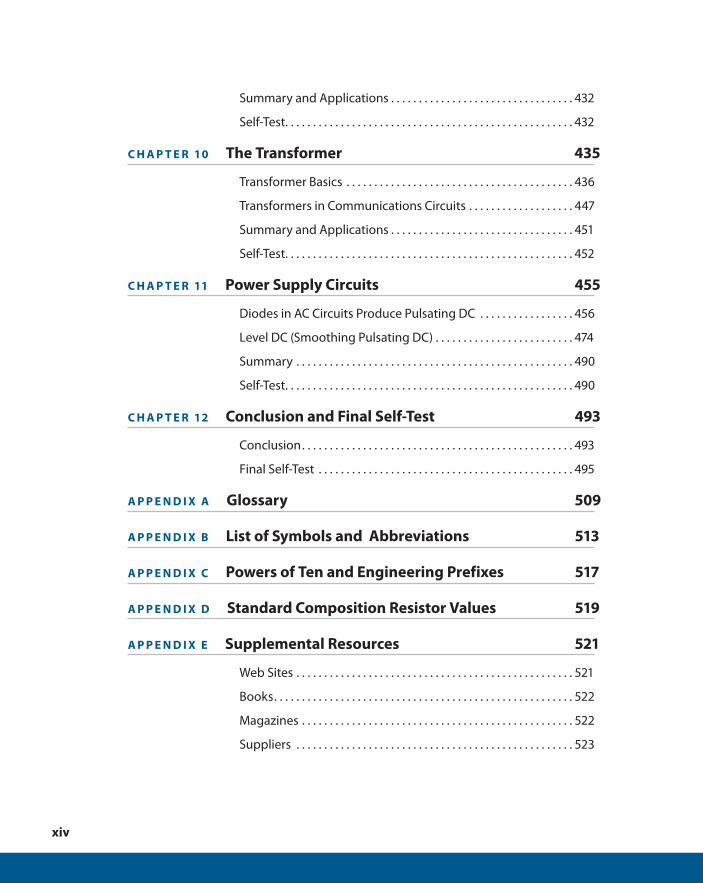
C H A P T E R 7 Resonant Circuits 267
The Capacitor and Inductor in Series . . . . . . . . . . . . . . . . . . . . . . . . 268
The Output Curve . . . . . . . . . . . . . . . . . . . . . . . . . . . . . . . . . . . . . . . . . . 286
Introduction to Oscillators . . . . . . . . . . . . . . . . . . . . . . . . . . . . . . . . . . 309
Summary . . . . . . . . . . . . . . . . . . . . . . . . . . . . . . . . . . . . . . . . . . . . . . . . . . 314
Self-Test. . . . . . . . . . . . . . . . . . . . . . . . . . . . . . . . . . . . . . . . . . . . . . . . . . . . 314
C H A P T E R 8 Transistor Amplifiers 319
Working with Transistor Amplifiers . . . . . . . . . . . . . . . . . . . . . . . . . . 320
A Stable Amplifier . . . . . . . . . . . . . . . . . . . . . . . . . . . . . . . . . . . . . . . . . . 330
Biasing . . . . . . . . . . . . . . . . . . . . . . . . . . . . . . . . . . . . . . . . . . . . . . . . . . . . . 334
The Emitter Follower . . . . . . . . . . . . . . . . . . . . . . . . . . . . . . . . . . . . . . . 350
Analyzing an Amplifier . . . . . . . . . . . . . . . . . . . . . . . . . . . . . . . . . . . . . 356
The JFET as an Amplifier . . . . . . . . . . . . . . . . . . . . . . . . . . . . . . . . . . . . 361
The Operational Amplifier . . . . . . . . . . . . . . . . . . . . . . . . . . . . . . . . . . 370
Summary . . . . . . . . . . . . . . . . . . . . . . . . . . . . . . . . . . . . . . . . . . . . . . . . . . 380
Self-Test. . . . . . . . . . . . . . . . . . . . . . . . . . . . . . . . . . . . . . . . . . . . . . . . . . . . 380
C H A P T E R 9 Oscillators 385
Understanding Oscillators . . . . . . . . . . . . . . . . . . . . . . . . . . . . . . . . . . 386
Feedback . . . . . . . . . . . . . . . . . . . . . . . . . . . . . . . . . . . . . . . . . . . . . . . . . . 396
The Colpitts Oscillator . . . . . . . . . . . . . . . . . . . . . . . . . . . . . . . . . . . . . . 402
The Hartley Oscillator. . . . . . . . . . . . . . . . . . . . . . . . . . . . . . . . . . . . . . . 414
The Armstrong Oscillator . . . . . . . . . . . . . . . . . . . . . . . . . . . . . . . . . . . 421
Practical Oscillator Design . . . . . . . . . . . . . . . . . . . . . . . . . . . . . . . . . . 422
Simple Oscillator Design Procedure . . . . . . . . . . . . . . . . . . . . . . . . . 423
Oscillator Troubleshooting Checklist . . . . . . . . . . . . . . . . . . . . . . . . 426
Book Author ftoc V1 December 28, 2015 6:44 PM
ftoc.indd 13 12/31/2015 7:32:18 PM
xiv
Summary and Applications . . . . . . . . . . . . . . . . . . . . . . . . . . . . . . . . . 432
Self-Test. . . . . . . . . . . . . . . . . . . . . . . . . . . . . . . . . . . . . . . . . . . . . . . . . . . . 432
C H A P T E R 10 The Transformer 435
Transformer Basics . . . . . . . . . . . . . . . . . . . . . . . . . . . . . . . . . . . . . . . . . 436
Transformers in Communications Circuits . . . . . . . . . . . . . . . . . . . 447
Summary and Applications . . . . . . . . . . . . . . . . . . . . . . . . . . . . . . . . . 451
Self-Test. . . . . . . . . . . . . . . . . . . . . . . . . . . . . . . . . . . . . . . . . . . . . . . . . . . . 452
C H A P T E R 11 Power Supply Circuits 455
Diodes in AC Circuits Produce Pulsating DC . . . . . . . . . . . . . . . . . 456
Level DC (Smoothing Pulsating DC) . . . . . . . . . . . . . . . . . . . . . . . . . 474
Summary . . . . . . . . . . . . . . . . . . . . . . . . . . . . . . . . . . . . . . . . . . . . . . . . . . 490
Self-Test. . . . . . . . . . . . . . . . . . . . . . . . . . . . . . . . . . . . . . . . . . . . . . . . . . . . 490
C H A P T E R 12 Conclusion and Final Self-Test 493
Conclusion . . . . . . . . . . . . . . . . . . . . . . . . . . . . . . . . . . . . . . . . . . . . . . . . . 493
Final Self-Test . . . . . . . . . . . . . . . . . . . . . . . . . . . . . . . . . . . . . . . . . . . . . . 495
A P P E N D I X A Glossary 509
A P P E N D I X B List of Symbols and Abbreviations 513
A P P E N D I X C Powers of Ten and Engineering Prefixes 517
A P P E N D I X D Standard Composition Resistor Values 519
A P P E N D I X E Supplemental Resources 521
Web Sites . . . . . . . . . . . . . . . . . . . . . . . . . . . . . . . . . . . . . . . . . . . . . . . . . . 521
Books . . . . . . . . . . . . . . . . . . . . . . . . . . . . . . . . . . . . . . . . . . . . . . . . . . . . . . 522
Magazines . . . . . . . . . . . . . . . . . . . . . . . . . . . . . . . . . . . . . . . . . . . . . . . . . 522
Suppliers . . . . . . . . . . . . . . . . . . . . . . . . . . . . . . . . . . . . . . . . . . . . . . . . . . 523
Book Author ftoc V1 December 28, 2015 6:44 PM
ftoc.indd 14 12/31/2015 7:32:18 PM
xv
A P P E N D I X F Equation Reference 525
A P P E N D I X G Schematic Symbols Used in This Book 529
Index 533
Book Author ftoc V1 December 28, 2015 6:44 PM
ftoc.indd 15 12/31/2015 7:32:18 PM

Book Author flast V1 December 28, 2015 6:44 PM
flast.indd 16 12/31/2015 7:32:05 PM
xvii
Introduction
The rapid growth of modern electronics is truly a phenomenon. Electronic
devices (including cell phones, personal computers, portable MP3 players, and digital
cameras) are a big part of many of our daily lives. Many industries have been founded,
and older industries have been revamped, because of the availability and application of
modern electronics in manufacturing processes, as well as in electronic products. Elec-
tronic products are constantly evolving, and their impact on our lives, and even the way
we socialize, is substantial.
WHAT THIS BOOK TEACHES
Complete Electronics Self-Teaching Guide with Projects is for anyone who has a basic
understanding of electronics concepts and wants to understand the operation of com-
ponents found in the most common discrete circuits. The chapters focus on circuits that
are the building blocks for many common electronic devices, and on the very few (but
important) principles you need to know to work with electronics.
The arrangement and approach is completely different from any other book on elec-
tronics in that it uses a question-and-answer approach to help you understand how elec-
tronic circuits work. This book steps you through calculations for every example in an
easy-to-understand fashion, and you do not need to have a mathematical background
beyond first-year algebra to follow along.
For many of you, the best way to understand new concepts is by doing, rather
than reading or listening. This book reinforces your understanding of electronic
concepts by leading you through the calculations and concepts for key circuits, as
well as the construction of circuits. Projects interspersed throughout the material
enable you to get hands-on practice. You build many of the circuits and observe or
measure how they work.
Book Author flast V1 December 28, 2015 6:44 PM
flast.indd 17 12/31/2015 7:32:05 PM
xviii
Helpful sidebars are interspersed throughout the book to provide more information
about how components work, and how to choose the right component. Other sidebars
provide discussions of techniques for building and testing circuits. If you want this addi-
tional information, be sure to read these.
Understanding the circuits composed of discrete components and the applicable cal-
culations discussed is useful not only in building and designing circuits, but it also helps
you to work with integrated circuits (ICs). That’s because ICs use miniaturized compo-
nents (such as transistors, diodes, capacitors, and resistors) that function based on the
same rules as discrete components (along with some specific rules necessitated by the
extremely small size of IC components).
HOW THIS BOOK IS ORGANIZED
This book is organized with sets of problems that challenge you to think through a con-
cept or procedure, and then provides answers so that you can constantly check your
progress and understanding. Specifically, the chapters in this book are organized as
follows:
C H A P T E R 1 DC Review and Pre-Test—This chapter provides a review and pre-test on
the basic concepts, components, and calculations that are useful when working with
direct current (DC) circuits.
C H A P T E R 2 The Diode—This chapter teaches you about the diode, including how you
use diodes in DC circuits, the main characteristics of diodes, and calculations you can
use to determine current, voltage, and power.
C H A P T E R 3 Introduction to the Transistor—This chapter explores the transistor and
how it’s used in circuits. You also discover how bipolar junction transistors (BJTs) and
junction field effect transistors (JFETs) control the flow of electric current.
C H A P T E R 4 The Transistor Switch—This chapter examines the simplest and most
widespread application of the transistor: switching. In addition to learning how to design
a transistor circuit to drive a particular load, you also compare the switching action of a
JFET and a BJT.
C H A P T E R 5 AC Pre-Test and Review—This chapter examines the basic concepts and
equations for alternating current (AC) circuits. You discover how to use resistors and
capacitors in AC circuits, and learn related calculations.
Book Author flast V1 December 28, 2015 6:44 PM
flast.indd 18 12/31/2015 7:32:05 PM

xix
C H A P T E R 6 Filters—This chapter looks at how resistors, capacitors, and inductors are
used in high-pass filters and low-pass filters to pass or block AC signals above or below a
certain frequency.
C H A P T E R 7 Resonant Circuits—This chapter examines the use of capacitors, induc-
tors, and resistors in bandpass filters and band-reject filters to pass or block AC signals
in a band of frequencies. You also learn how to calculate the resonance frequency and
bandwidth of these circuits. This chapter also introduces the use of resonant circuits in
oscillators.
C H A P T E R 8 Transistor Amplifiers—This chapter explores the use of transistor ampli-
fiers to amplify electrical signals. In addition to examining the fundamental steps used to
design BJT-based amplifiers, you learn how to use JFETs and operational amplifiers (op-
amps) in amplifier circuits.
C H A P T E R 9 Oscillators —This chapter introduces you to the oscillator, a circuit that
produces a continuous AC output signal. You learn how an oscillator works and step
through the procedure to design and build an oscillator.
C H A P T E R 10 The Transformer—This chapter discusses how a transformer converts AC
voltage to a higher or lower voltage. You learn how a transformer makes this conversion
and how to calculate the resulting output voltage.
C H A P T E R 11 Power Supply Circuits—This chapter examines how power supplies con-
vert AC to DC with a circuit made up of transformers, diodes, capacitors, and resistors.
You also learn how to calculate the values of components that produce a specified DC
output voltage for a power supply circuit.
C H A P T E R 12 Conclusion and Final Self-Test—This chapter enables you to check your
overall knowledge of electronics concepts presented in this book through the use of a
final self-test.
In addition, this book contains the following appendixes for easy reference:
A P P E N D I X A Glossary—This appendix provides key electronics terms and their
definitions.
A P P E N D I X B List of Symbols and Abbreviations—This appendix gives you a handy ref-
erence of commonly used symbols and abbreviations.
A P P E N D I X C Powers of Ten and Engineering Prefixes—This appendix lists prefixes
commonly used in electronics, along with their corresponding values.
Book Author flast V1 December 28, 2015 6:44 PM
flast.indd 19 12/31/2015 7:32:05 PM

xx
A P P E N D I X D Standard Resistor Values—This appendix provides standard resistance
values for the carbon film resistor, the most commonly used type of resistor.
A P P E N D I X E Supplemental Resources—This appendix provides references to helpful
websites, books, and magazines.
A P P E N D I X F Equation Reference—This appendix serves as a quick guide to commonly
used equations, along with chapter and problem references showing you where they are
first introduced in this book.
A P P E N D I X G Schematic Symbols Used in This Book—This appendix provides a listing
of schematic symbols used in the problems found throughout the book.
CONVENTIONS USED IN THIS BOOK
As you study electronics, you will find that there is some variation in terminology and
the way that circuits are drawn. Following are three conventions followed in this book
that you should be aware of:
■ The discussions use “V” to stand for voltage, versus “E,” which you see used in
some other books.
■ In all circuit diagrams, intersecting lines indicate an electrical connection. (Some
other books use a dot at the intersection of lines to indicate a connection.) If a
semicircle appears at the intersection of two lines, it indicates that there is no con-
nection. See Figure 9.5 for an example of this.
■ The discussions in this book use conventional current flow to determine the flow
of electric current (from positive voltage to negative voltage), whereas some other
books use electron flow (from negative voltage to positive voltage).
HOW TO USE THIS BOOK
This book assumes that you have some knowledge of basic electronics such as Ohm’s law
and current flow. If you have read a textbook or taken a course on electronics, or if you
have worked with electronics, you probably have the prerequisite knowledge. If not, you
Book Author flast V1 December 28, 2015 6:44 PM
flast.indd 20 12/31/2015 7:32:05 PM
xxi
should read a book such as Electronics for Dummies (Indianapolis: Wiley, 2009) to get the
necessary background for this book. You can also go to the author’s Website
(www.BuildingGadgets.com) and use the Tutorial links to find useful online lessons in
electronics. In addition, Chapters 1 and 5 enable you to test your knowledge and review
the necessary basics of electronics.
You should read the chapters in order because often later material depends on con-
cepts and skills covered in earlier chapters.
Complete Electronics Self-Teaching Guide with Projects is presented in a self-teaching
format that enables you to learn easily, and at your own pace. The material is presented
in numbered sections called problems. Each problem presents some new information and
gives you questions to answer. To learn most effectively, you should cover up the answers
with a sheet of paper and try to answer each question. Then, compare your answer with
the correct answer that follows. If you miss a question, correct your answer and then go
on. If you miss many in a row, go back and review the previous section, or you may miss
the point of the material that follows.
Be sure to try to do all the projects. They are not difficult, and they help reinforce
your learning of the subject matter. If you don’t have the equipment to work through
a project, simply reading through it can help you to better understand the concepts it
demonstrates.
Each project includes a schematic, parts list, step-by-step instructions, and detailed
photos of the completed circuit. Working through these projects, you can test your skill
by building the circuit using just the schematic and parts list. If you want additional help,
check the photos showing the details of how the components are connected. A Camera
icon in the margin as shown here indicates that there is a color version of the figure in a
special insert in the paperback version of this book. If you purchased an electronic ver-
sion of this book, and have an e-reader without color capabilities, you can find the color
photos on the author’s website at www.buildinggadgets.com/complete-electronics.
htm.
This website also provides project pages that include links to suppliers. These pages
are kept up-to-date with supplier part numbers for the components you need.
When you reach the end of a chapter, evaluate your learning by taking the Self-Test.
If you miss any questions, review the related parts of the chapter again. If you do well on
the Self-Test, you’re ready to go to the next chapter. You may also find the Self-Test useful
as a review before you start the next chapter. At the end of the book, there is a Final Self-
Test that enables you to assess your overall learning.
Book Author flast V1 December 28, 2015 6:44 PM
flast.indd 21 12/31/2015 7:32:05 PM
xxii
You can work through this book alone, or you can use it with a course. If you use the book
alone, it serves as an introduction to electronics but is not a complete course. For that reason,
at the end of the book are some suggestions for further reading and online resources. Also, at
the back of the book is a table of symbols and abbreviations for reference and review.
Now you’re ready to learn electronics!
Book Author flast V1 December 28, 2015 6:44 PM
flast.indd 22 12/31/2015 7:32:05 PM
1DC Review and Pre-Test
Electronics cannot be studied without first under-
standing the basics of electricity. This chapter is a
review and pre-test on those aspects of direct current
(DC) that apply to electronics. By no means does it
cover the whole DC theory, but merely those topics
that are essential to simple electronics.
This chapter reviews the following:
■ Current flow
■ Potential or voltage difference
■ Ohm’s law
■ Resistors in series and parallel
Book Author c01 V1 12/30/2015 6:12 PM
c01.indd 1 12/31/2015 6:06:54 PM
CHAPTER 1 DC REVIEW AND PRE-TEST2
■ Power
■ Small currents
■ Resistance graphs
■ Kirchhoff’s Voltage Law
■ Kirchhoff’s Current Law
■ Voltage and current dividers
■ Switches
■ Capacitor charging and discharging
■ Capacitors in series and parallel
CURRENT FLOW
1 Electrical and electronic devices work because of an electric current.
QUESTION
What is an electric current?
ANSWER
An electric current is a flow of electric charge. The electric charge usually consists
of negatively charged electrons. However, in semiconductors, there are also positive
charge carriers called holes.
2 There are several methods that can be used to generate an electric current.
QUESTION
Write at least three ways an electron flow (or current) can be generated.
Book Author c01 V1 12/30/2015 6:12 PM
c01.indd 2 12/31/2015 6:06:54 PM
CURRENT FLOW 3
ANSWER
The following is a list of the most common ways to generate current:
■ Magnetically—This includes the induction of electrons in a wire rotating within a
magnetic field. An example of this would be generators turned by water, wind, or
steam, or the fan belt in a car.
■ Chemically—This involves the electrochemical generation of electrons by reac-
tions between chemicals and electrodes (as in batteries).
■ Photovoltaic generation of electrons—This occurs when light strikes semiconduc-
tor crystals (as in solar cells).
Less common methods to generate an electric current include the following:
■ Thermal generation—This uses temperature differences between thermocouple
junctions. Thermal generation is used in generators on spacecrafts that are fueled
by radioactive material.
■ Electrochemical reaction—This occurs between hydrogen, oxygen, and electrodes
(fuel cells).
■ Piezoelectrical—This involves mechanical deformation of piezoelectric substances.
For example, piezoelectric material in the heels of shoes power LEDs that light up
when you walk.
3 Most of the simple examples in this book contain a battery as the voltage source. As
such, the source provides a potential difference to a circuit that enables a current to flow.
An electric current is a flow of electric charge. In the case of a battery, electrons are the
electric charge, and they flow from the terminal that has an excess number of electrons to
the terminal that has a deficiency of electrons. This flow takes place in any complete cir-
cuit that is connected to battery terminals. It is this difference in the charge that creates
the potential difference in the battery. The electrons try to balance the difference.
Because electrons have a negative charge, they actually flow from the negative ter-
minal and return to the positive terminal. This direction of flow is called electron flow.
Most books, however, use current flow, which is in the opposite direction. It is referred to
as conventional current flow, or simply current flow. In this book, the term conventional
current flow is used in all circuits.
Later in this book, you see that many semiconductor devices have a symbol that con-
tains an arrowhead pointing in the direction of conventional current flow.
Book Author c01 V1 12/30/2015 6:12 PM
c01.indd 3 12/31/2015 6:06:54 PM
CHAPTER 1 DC REVIEW AND PRE-TEST4
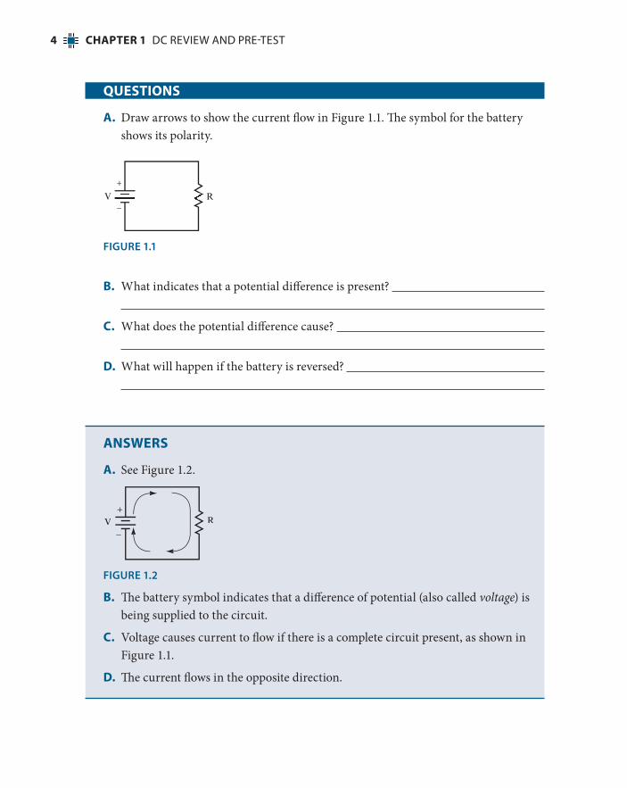
QUESTIONS
A. Draw arrows to show the current flow in Figure 1.1. The symbol for the battery
shows its polarity.
V R+
−
FIGURE 1.1
B. What indicates that a potential difference is present?
C. What does the potential difference cause?
D. What will happen if the battery is reversed?
ANSWERS
A. See Figure 1.2.
V R+
−
FIGURE 1.2
B. The battery symbol indicates that a difference of potential (also called voltage) is
being supplied to the circuit.
C. Voltage causes current to flow if there is a complete circuit present, as shown in
Figure 1.1.
D. The current flows in the opposite direction.
Book Author c01 V1 12/30/2015 6:12 PM
c01.indd 4 12/31/2015 6:06:55 PM

OHM’S LAW 5
OHM’S LAW
4 Ohm’s law states the fundamental relationship between voltage, current, and resistance.
QUESTION
What is the algebraic formula for Ohm’s law?
ANSWER
V I R5 3
This is the most basic equation in electricity, and you should know it well. Some
electronics books state Ohm’s law as E 5 IR. E and V are both symbols for voltage.
This book uses V to indicate voltage. When V is used after a number in equations
and circuit diagrams, it represents volts, the unit of measurement of voltage. Also, in
this formula, resistance is the opposition to current flow. Larger resistance results in
smaller current for any given voltage.
5 Use Ohm’s law to find the answers in this problem.
QUESTIONS
What is the voltage for each combination of resistance and current values?
A. R 5 20 ohms, I 5 0.5 amperes
V 5
B. R 5 560 ohms, I 5 0.02 amperes
V 5
C. R 5 1,000 ohms, I 5 0.01 amperes
V 5
D. R 5 20 ohms I 5 1.5 amperes
V 5
Book Author c01 V1 12/30/2015 6:12 PM
c01.indd 5 12/31/2015 6:06:55 PM
CHAPTER 1 DC REVIEW AND PRE-TEST6
ANSWERS
A. 10 volts
B. 11.2 volts
C. 10 volts
D. 30 volts
6 You can rearrange Ohm’s law to calculate current values.
QUESTIONS
What is the current for each combination of voltage and resistance values?
A. V 5 1 volt, R 5 2 ohms
I 5
B. V 5 2 volts, R 5 10 ohms
I 5
C. V 5 10 volts, R 5 3 ohms
I 5
D. V 5 120 volts, R 5 100 ohms
I 5
ANSWERS
A. 0.5 amperes
B. 0.2 amperes
C. 3.3 amperes
D. 1.2 amperes
7 You can rearrange Ohm’s law to calculate resistance values.
Book Author c01 V1 12/30/2015 6:12 PM
c01.indd 6 12/31/2015 6:06:55 PM
Recommended