External Gear Pumps
Series S
AZPS-...
Fixed pumpsV = 4.0...28 cm3/rev
RE 10 095/02.12Replaces:RE 10 095/09.09
Overview of contents
Contents Page
General 2
Product overview 3
Ordering code single pumps 4
Ordering code multiple pumps 5
Drive shaft 6
Front cover 7
Line ports 8
Pumps with integral valves 9
Design calculations for pumps 9
Performance charts 10
Noise charts 13
Specifications 15
Drive arrangements 16
Multiple pumps through drives 18
Dimensions 19
Fittings 28
Overview of part numbers 29
Notes for commissioning 30
Service parts 31
Features
– Nominal pressure 280 bar
– Slide bearings for heavy duty applications
– Drive shafts to ISO or SAE
– Combination of several pumps possible
– Line ports:
connection flange or screw thread
– Optimized pressure pulsation with reduced noise emissions
and vibration excitation in the system
– Consistent high quality
– Considerably longer service life due to reinforced shaft and
case
2/32 Bosch Rexroth AG Hydraulics AZPS RE 10 095/02.12
GeneralThe key task of external gear units is to convert mechanical
energy (torque and rotational speed) into hydraulic energy
(flow and pressure). In external gear motors this is the other
way round. These machines are required to be highly efficient
in order to avoid unnecessary heat. This efficiency is achieved
by means of precision production engineering and pressure-
sensitive gap sealing.
Moreover, in the low-noise SILENCE pumps, the dual-flank
principle helps to reduce flow pulsation by up to 75 %.
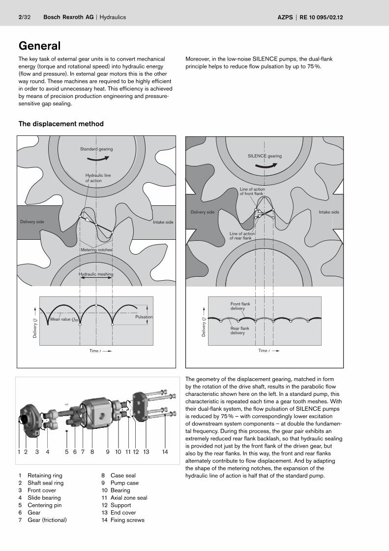
The displacement method
The geometry of the displacement gearing, matched in form
by the rotation of the drive shaft, results in the parabolic flow
characteristic shown here on the left. In a standard pump, this
characteristic is repeated each time a gear tooth meshes. With
their dual-flank system, the flow pulsation of SILENCE pumps
is reduced by 75 % – with correspondingly lower excitation
of downstream system components – at double the fundamen-
tal frequency. During this process, the gear pair exhibits an
extremely reduced rear flank backlash, so that hydraulic sealing
is provided not just by the front flank of the driven gear, but
also by the rear flanks. In this way, the front and rear flanks
alternately contribute to flow displacement. And by adapting
the shape of the metering notches, the expansion of the
hydraulic line of action is half that of the standard pump. 1 Retaining ring
2 Shaft seal ring
3 Front cover
4 Slide bearing
5 Centering pin
6 Gear
7 Gear (frictional)
8 Case seal
9 Pump case
10 Bearing
11 Axial zone seal
12 Support
13 End cover
14 Fixing screws
1 2 3 4 5 6 7 8 9 10 11 12 13 14
Intake side
Line of actionof rear flank
Front flankdelivery
Rear flankdelivery
Deliv
ery
Q
Time t
Delivery side
Line of actionof front flank
SILENCE gearing
Mean value Qm
Time t
Pulsation
Intake sideDelivery side
Hydraulic line
of action
Metering notches
Hydraulic meshing
Deliv
ery
Q
Standard gearing
Hydraulics Bosch Rexroth AGAZPS RE 10 095/02.12 3/32
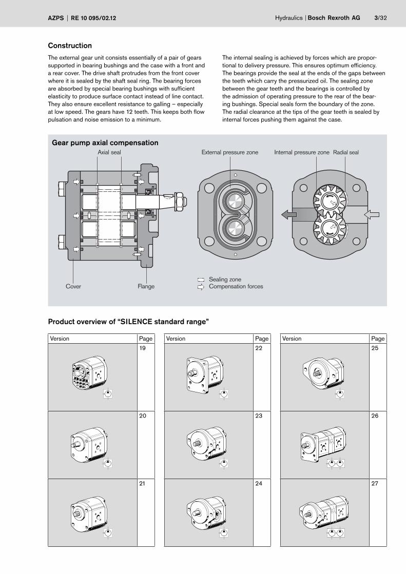
Construction
The external gear unit consists essentially of a pair of gears
supported in bearing bushings and the case with a front and
a rear cover. The drive shaft protrudes from the front cover
where it is sealed by the shaft seal ring. The bearing forces
are absorbed by special bearing bushings with sufficient
elasticity to produce surface contact instead of line contact.
They also ensure excellent resistance to galling – especially
at low speed. The gears have 12 teeth. This keeps both flow
pulsation and noise emission to a minimum.
The internal sealing is achieved by forces which are propor-
tional to delivery pressure. This ensures optimum efficiency.
The bearings provide the seal at the ends of the gaps between
the teeth which carry the pressurized oil. The sealing zone
between the gear teeth and the bearings is controlled by
the admission of operating pressure to the rear of the bear-
ing bushings. Special seals form the boundary of the zone.
The radial clearance at the tips of the gear teeth is sealed by
internal forces pushing them against the case.
Cover
Axial seal Radial seal External pressure zone
Flange Compensation forcesSealing zone
Internal pressure zone
Gear pump axial compensation
Product overview of “SILENCE standard range”
Version Page
19
20
21
Version Page
22
23
24
Version Page
25
26
27
4/32 Bosch Rexroth AG Hydraulics AZPS RE 10 095/02.12
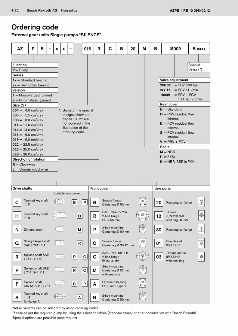
AZ P S – x x – 016 R C B 20 M B 18009 S xxxx
Ordering code External gear units Single pumps “SILENCE”
Function
P = Pump
Series
1x = Standard bearing
2x = Reinforced bearing
Version
1 = Phosphatized, pinned
2 = Chromatized, pinned
Size (S)
004 = 4.0 cm3/rev
005 = 5.5 cm3/rev
008 = 8.0 cm3/rev
011 = 11.0 cm3/rev
014 = 14.0 cm3/rev
016 = 16.0 cm3/rev
019 = 19.0 cm3/rev
022 = 22.5 cm3/rev
025 = 25.0 cm3/rev
028 = 28.0 cm3/rev
*) Some of the special
designs shown on
pages 19–27 are
not covered in the
illustration of the
ordering code.
Direction of rotation
R = Clockwise
L = Counter-clockwise
Special
design *)
Valve adjustment
200 xx = PRV 200 bar
xxx 11 = FCV 11 l/min
18009 = PRV + FCV
180 bar, 9 l/min
Rear cover
B = Standard
D = PRV residual flow
internal
E = FCV residual flow
external
S = FCV residual flow
internal
V = PRV + FCV
Seals
M = NBR
P = FKM
K = NBR, SSR in FKM
Drive shafts Front cover Line ports
Suitable front cover
CTapered key shaft
1 : 5B P B
Square flange
Centering Ø 80 mm 20 Rectangular flange
HTapered key shaft
1 : 8O R
SAE J 744 82-2 A
2-bolt flange
Ø 82.55 mm12
Thread
(UN-2B) SAE
seal ring BOSS
N Dihedral claw M P 2-bolt mounting
Centering Ø 50 mm 30 Rectangular flange
QStraight keyed shaft
SAE J 744 16-1R O
Square flange
Centering Ø 36.47 mm 01Pipe thread
ISO 228/1
RSplined shaft SAE
J 744 16-4 9TR C C
SAE J 744 101-2 B
2-bolt flange
Ø 101.6 mm03
Thread, metric
ISO 6149
with seal ring
PSplined shaft SAE
J 744 19-4 11TR C M
2-bolt mounting
Centering Ø 52 mm
with seal ring
FSplined shaft
DIN 5482 B 17 x 14B P A
Outboard bearing
Ø 80 mm, Type 1
STapered key shaft
1 : 5
for flange A
A N 2-bolt mounting
Centering Ø 50 mm
Not all variants can be selected by using ordering code!
Please select the required pump by using the selection tables (standard types) or after consultation with Bosch Rexroth!
Special options are possible upon request.
Hydraulics Bosch Rexroth AGAZPS RE 10 095/02.12 5/32
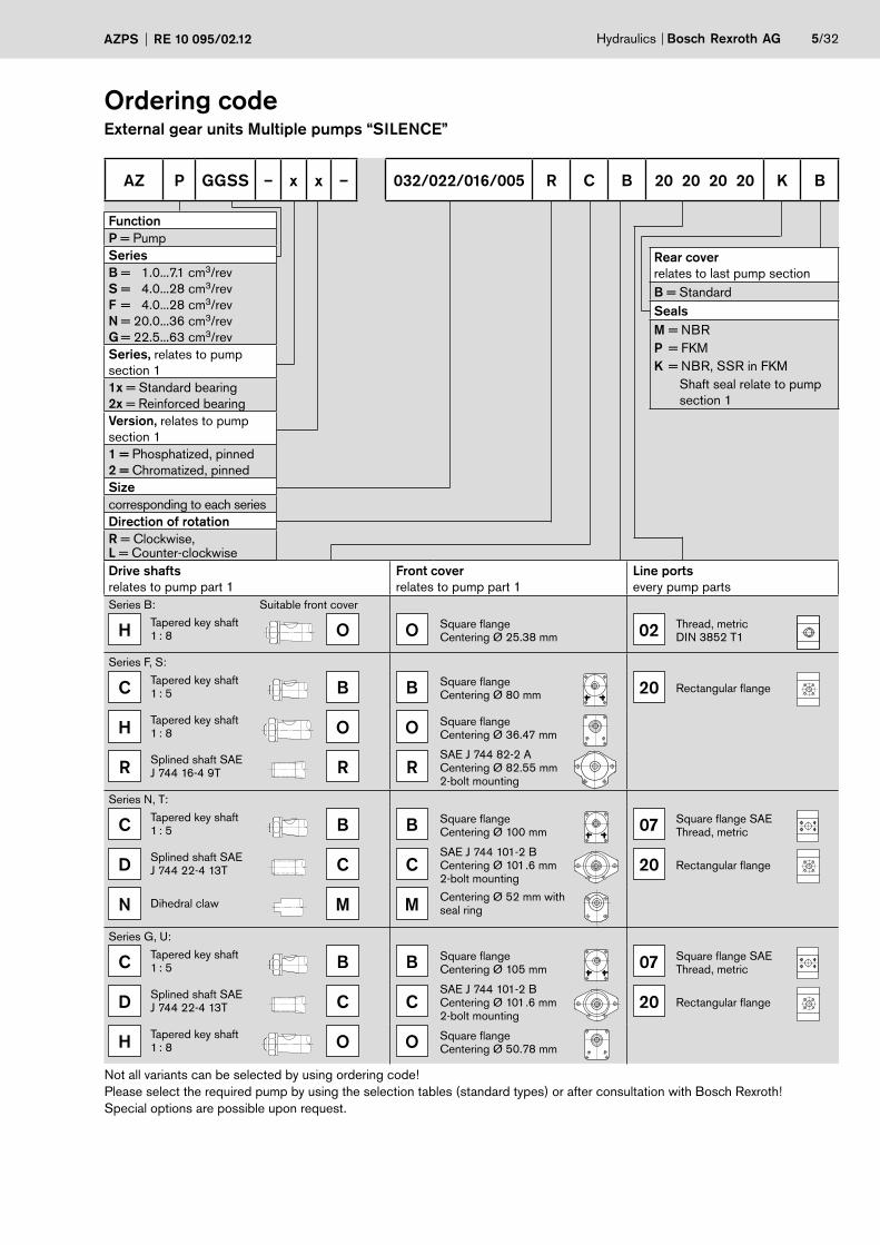
AZ P GGSS – x x – 032/022/016/005 R C B 20 20 20 20 K B
Ordering code External gear units Multiple pumps “SILENCE”
Function
P = Pump
Series
B = 1.0...7.1 cm3/rev
S = 4.0...28 cm3/rev
F = 4.0...28 cm3/rev
N = 20.0...36 cm3/rev
G = 22.5...63 cm3/rev
Series, relates to pump
section 1
1x = Standard bearing
2x = Reinforced bearing
Version, relates to pump
section 1
1 = Phosphatized, pinned
2 = Chromatized, pinned
Size
corresponding to each series
Direction of rotation
R = Clockwise, L = Counter-clockwise
Rear cover
relates to last pump section
B = Standard
Seals
M = NBR
P = FKM
K = NBR, SSR in FKM
Shaft seal relate to pump
section 1
Drive shafts
relates to pump part 1
Front cover
relates to pump part 1
Line ports
every pump parts
Series B: Suitable front cover
HTapered key shaft 1 : 8 O O
Square flangeCentering Ø 25.38 mm 02
Thread, metricDIN 3852 T1
Series F, S:
CTapered key shaft 1 : 5 B B
Square flangeCentering Ø 80 mm 20 Rectangular flange
HTapered key shaft 1 : 8 O O
Square flangeCentering Ø 36.47 mm
RSplined shaft SAEJ 744 16-4 9T R R
SAE J 744 82-2 A Centering Ø 82.55 mm2-bolt mounting
Series N, T:
CTapered key shaft 1 : 5 B B
Square flangeCentering Ø 100 mm 07
Square flange SAEThread, metric
DSplined shaft SAEJ 744 22-4 13T C C
SAE J 744 101-2 B Centering Ø 101.6 mm2-bolt mounting
20 Rectangular flange
N Dihedral claw M M Centering Ø 52 mm with seal ring
Series G, U:
CTapered key shaft 1 : 5 B B
Square flangeCentering Ø 105 mm 07
Square flange SAEThread, metric
DSplined shaft SAEJ 744 22-4 13T C C
SAE J 744 101-2 B Centering Ø 101.6 mm2-bolt mounting
20 Rectangular flange
HTapered key shaft 1 : 8 O O
Square flangeCentering Ø 50.78 mm
Not all variants can be selected by using ordering code!
Please select the required pump by using the selection tables (standard types) or after consultation with Bosch Rexroth!
Special options are possible upon request.
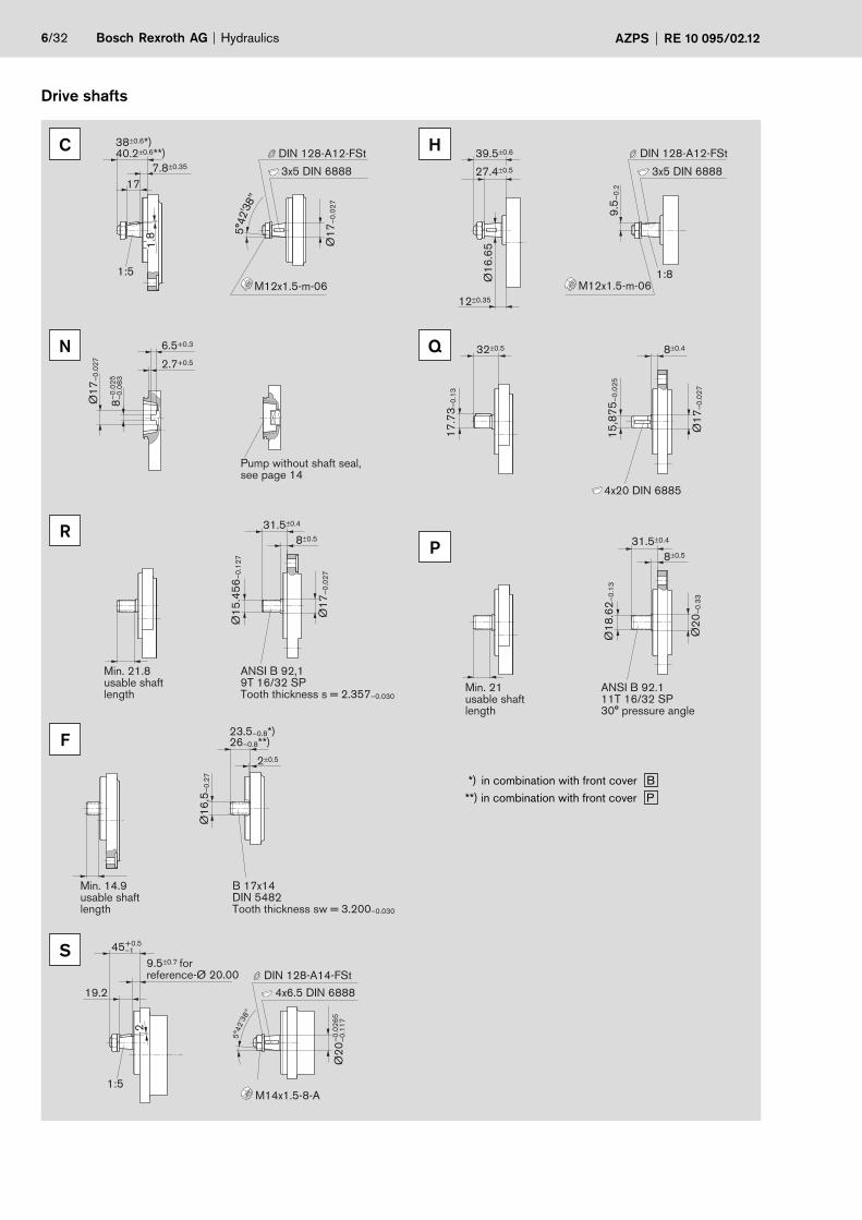
6/32 Bosch Rexroth AG Hydraulics AZPS RE 10 095/02.12
Drive shafts
3x5 DIN 6888
M12x1.5-m-06
DIN 128-A12-FSt
17
1:5
1.8
5°4
2'3
8"
7.8±0.35
40.2±0.6**)38±0.6*)
Ø1
7–
0.0
27
9.5
–0
.2
Ø1
6.6
5
3x5 DIN 6888
M12x1.5-m-06
DIN 128-A12-FSt
1:8
39.5±0.6
27.4±0.5
12±0.35
H
2.7+0.5
6.5+0.3
Ø1
7–
0.0
27
Pump without shaft seal, see page 14
–0
.02
5
8–
0.0
83
15
,87
5–
0.0
25
17
.73
–0
.13
32±0.5
Ø1
7–
0.0
27
8±0.4
4x20 DIN 6885
Q
Ø1
7–
0.0
27
Ø1
5.4
56
–0
.12
7
31.5±0.4
8±0.5
Min. 21.8 usable shaft length
ANSI B 92,1 9T 16/32 SP Tooth thickness s = 2.357–0.030
Min. 21 usable shaft length
Ø1
8.6
2–
0.1
3
31.5±0.4
8±0.5
ANSI B 92.1 11T 16/32 SP 30° pressure angle
Ø2
0–
0.3
3
P
Ø1
6,5
–0
.27
26–0.8**)23.5–0.8*)
2±0.5
Min. 14.9 usable shaft length
B 17x14 DIN 5482 Tooth thickness sw = 3.200–0.030
1:5
4x6.5 DIN 6888
M14x1.5-8-A
DIN 128-A14-FSt
5°4
2'3
8"
+0.5 45–1
19.2
9.5±0.7 for reference-Ø 20.00
–0
.02
65
Ø
20
–0
.11
7
2
C
N
R
F
S
*) in combination with front cover B
**) in combination with front cover P
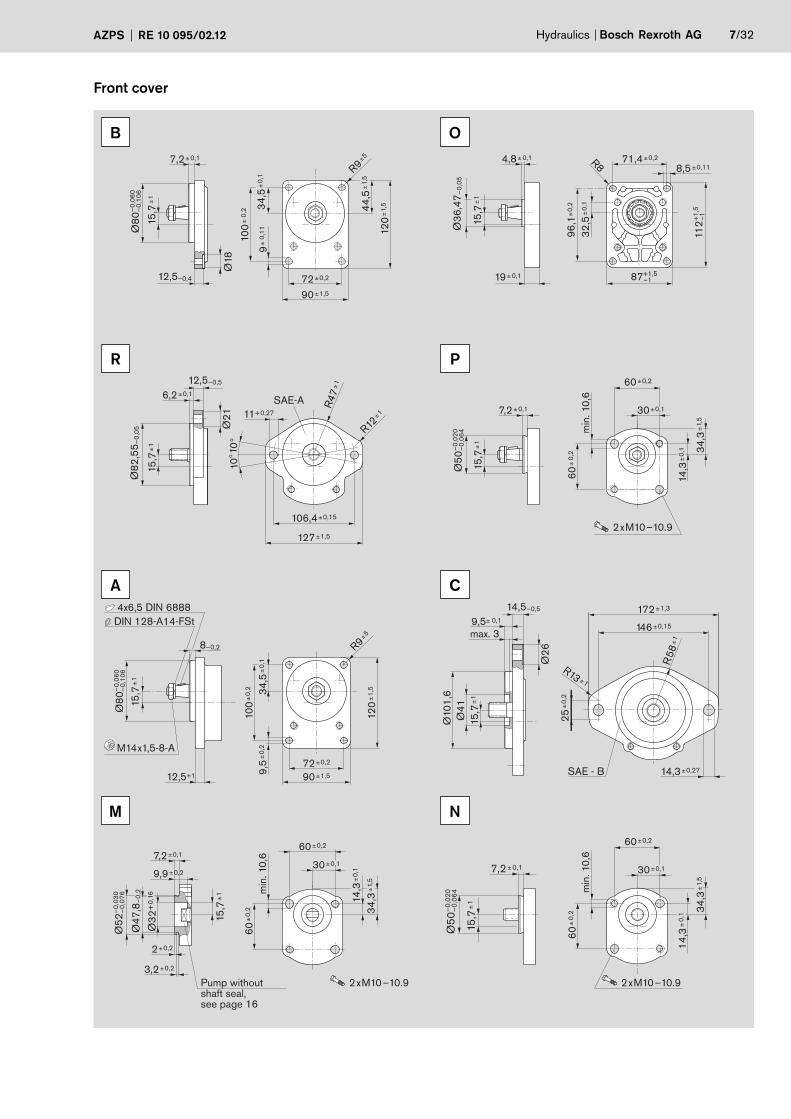
Hydraulics Bosch Rexroth AGAZPS RE 10 095/02.12 7/32
Front cover
72±0,2
100±
0,2 34
,5±
0,1
9±
0,11
44,5
±1,
5
120±
1,5
90±1,5
12,5–0,4
15,7
±1
7,2±0,1
Ø18
Ø80
–0,
060
–0,
106
R9±5
B
112+
1,5
–1
87+1,5–1
Ø36
,47 –
0,05
15
,7±
1
32,5
±0,
1
71,4±0,2
8,5±0,11
96,1
±0,
2
4,8±0,1
19±0,1
R8
O
SAE-A6,2±0,1
106,4±0,15
11+0,27
10°
10°
127±1,5
R47
±112,5–0,5
15,7
±1
Ø21
Ø82
,55 –
0,05 R12
±1
R
Ø50
–0,
020
–0,
064
7,2±0,1
15,7
±1
60±
0,2
14,3
±0,
1 34,3
±1,
5
60±0,2
30±0,1
min
. 10,
6
2xM10–10.9
P
12,5+1
8–0,2
Ø80
–0,
060
–0,
106
15,7
±1
120±
1,5
100±
0,2
9,5±
0,2
90±1,5
72±0,2
34,5
±0,
1
R9±5
4x6,5 DIN 6888
M14x1,5-8-A
DIN 128-A14-FSt
A
SAE - B
Ø10
1,6
Ø41
14,5–0,5
15,7
±1
25±
0,2
Ø26
9,5± 0,1
14,3±0,27
146±0,15
172±1,3
max. 3
R58
±1
R13 ±1
C
Pump withoutshaft seal, see page 16
Ø52
–0,
030
–0,
076
Ø47
,8–
0,2
Ø32
+0,
16
15,7
±1
14,3
±0,
1
34,3
±1,
5
30±0,1
60±0,2
60±
0,2
7,2±0,1
2±0,2
3,2±0,2
9,9±0,2
min
. 10,
6
2xM10–10.9
M
2xM10–10.9
Ø50
–0,
020
–0,
064
34,3
±1,
5
60±
0,2
60±0,2
30±0,1
min
. 10,
6
14,3
±0,
1
15,7
±1
7,2±0,1
N
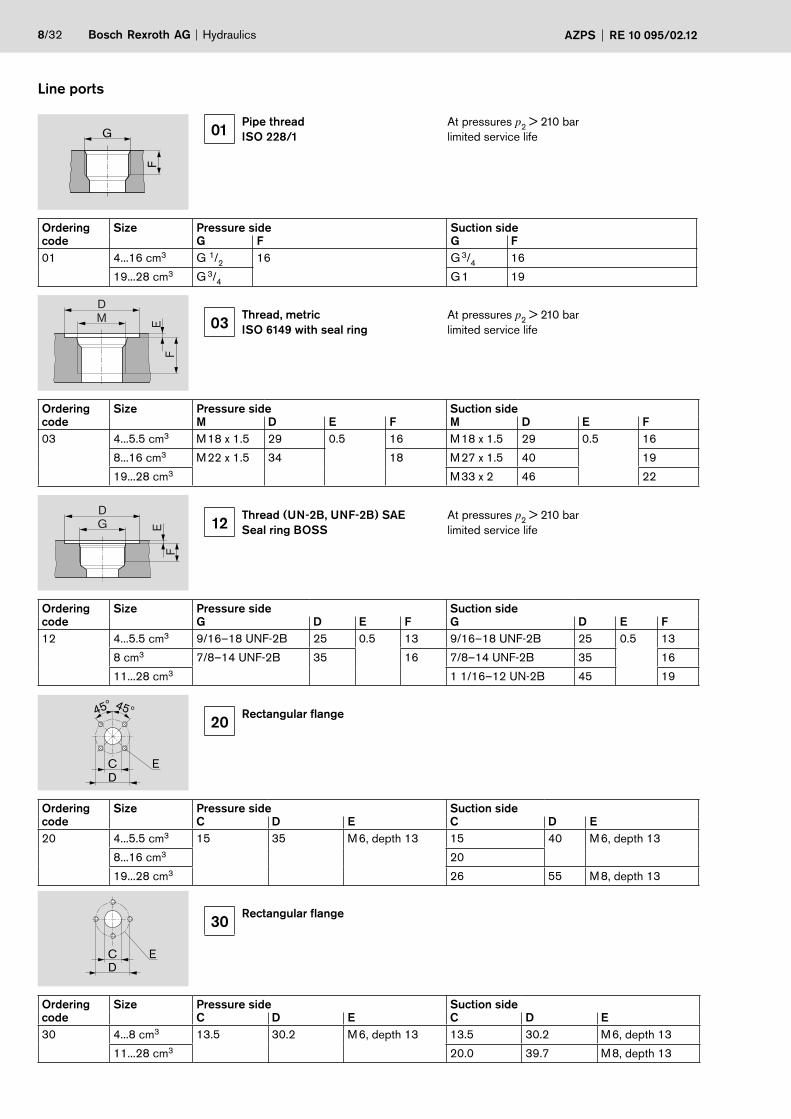
8/32 Bosch Rexroth AG Hydraulics AZPS RE 10 095/02.12
Line ports
01Pipe thread
ISO 228/1
At pressures p2 > 210 bar
limited service life
F
G
03 Thread, metric
ISO 6149 with seal ring
At pressures p2 > 210 bar
limited service life
D
M
EF
12 Thread (UN-2B, UNF-2B) SAE
Seal ring BOSS
At pressures p2 > 210 bar
limited service life
DG E
F
20 Rectangular flange
45°45°
C
D
E
30 Rectangular flange
ECD
Ordering Size Pressure side Suction side
code C D E C D E
30 4...8 cm3 13.5 30.2 M 6, depth 13 13.5 30.2 M 6, depth 13
11...28 cm3 20.0 39.7 M 8, depth 13
Ordering Size Pressure side Suction side
code G D E F G D E F
12 4...5.5 cm3 9/16–18 UNF-2B 25 0.5 13 9/16–18 UNF-2B 25 0.5 13
8 cm3 7/8–14 UNF-2B 35 16 7/8–14 UNF-2B 35 16
11...28 cm3 1 1/16–12 UN-2B 45 19
Ordering Size Pressure side Suction side
code C D E C D E
20 4...5.5 cm3 15 35 M 6, depth 13 15 40 M 6, depth 13
8...16 cm3 20
19...28 cm3 26 55 M 8, depth 13
Ordering Size Pressure side Suction side
code G F G F
01 4...16 cm3 G 1/2
16 G 3/4
16
19...28 cm3 G 3/4
G 1 19
Ordering Size Pressure side Suction side
code M D E F M D E F
03 4...5.5 cm3 M 18 x 1.5 29 0.5 16 M 18 x 1.5 29 0.5 16
8...16 cm3 M 22 x 1.5 34 18 M 27 x 1.5 40 19
19...28 cm3 M 33 x 2 46 22
Hydraulics Bosch Rexroth AGAZPS RE 10 095/02.12 9/32
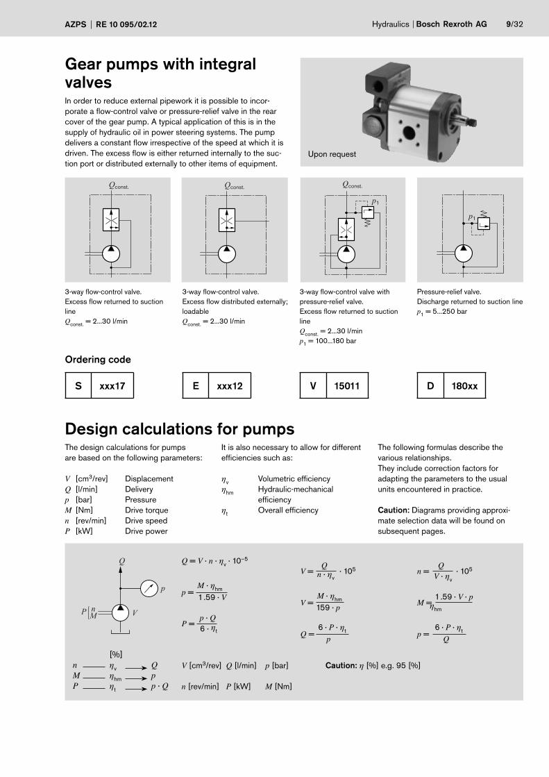
Gear pumps with integral
valvesIn order to reduce external pipework it is possible to incor-
porate a flow-control valve or pressure-relief valve in the rear
cover of the gear pump. A typical application of this is in the
supply of hydraulic oil in power steering systems. The pump
delivers a constant flow irrespective of the speed at which it is
driven. The excess flow is either returned internally to the suc-
tion port or distributed externally to other items of equipment.
Qconst. Qconst.Qconst.
p1
p1
3-way flow-control valve.
Excess flow returned to suction
line
Qconst.
= 2...30 l/min
3-way flow-control valve.
Excess flow distributed externally;
loadable
Qconst.
= 2...30 l/min
3-way flow-control valve with
pressure-relief valve.
Excess flow returned to suction
line
Qconst.
= 2...30 l/min
p1 = 100...180 bar
Pressure-relief valve.
Discharge returned to suction line
p1 = 5...250 bar
Ordering code
S xxx17 E xxx12 V 15011 D 180xx
The design calculations for pumps
are based on the following parameters:
V [cm3/rev] Displacement
Q [l/min] Delivery
p [bar] Pressure
M [Nm] Drive torque
n [rev/min] Drive speed
P [kW] Drive power
It is also necessary to allow for different
efficiencies such as:
ηv Volumetric efficiency
ηhm
Hydraulic-mechanical
efficiency
ηt Overall efficiency
The following formulas describe the
various relationships.
They include correction factors for
adapting the parameters to the usual
units encountered in practice.
Caution: Diagrams providing approxi-
mate selection data will be found on
subsequent pages.
Design calculations for pumps
V
Q
p
P Mn
[%]
n ηv
QM η
hm p
P ηt
p · Q
Q = V · n · ηv · 10–5
M · ηhm p =
1.59 · V
p · Q
P = 6 · ηt
QV = · 105 n · η
v
M · ηhmV =
159 · p
6 · P · ηtQ =
p
Qn = · 105
V · ηv
1.59 · V · pM = ηhm
6 · P · ηtp =
Q
V [cm3/rev] Q [l/min] p [bar] Caution: η [%] e.g. 95 [%]
n [rev/min] P [kW] M [Nm]
Upon request
10/32 Bosch Rexroth AG Hydraulics AZPS RE 10 095/02.12
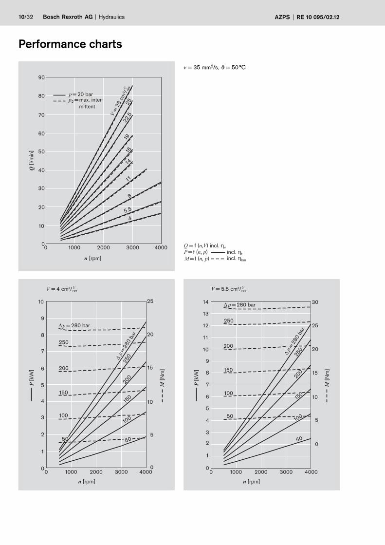
Performance charts
0 1000 2000 3000 4000
60
0
10
20
30
40
50
90
80
70
n [rpm]
Q [
l/m
in]
V =
28 c
m3 /
19
16
22.5
25
14
11
8
5.5
4
U
rev
p = 20 bar p2 = max. inter-
mittent
n [rpm]
0 1000 2000 4000 3000 0
5
10
15
20
25
8
7
10
9
6
5
4
3
2
1
0
p = 280 bar
250
200
150
50
100
p =
280 b
ar
250
200
150
100
50
P [
kW
]
M [
Nm
]
V = 4 cm3/ U rev
250
200
150
50
100
250
200
150
100
50
n [rpm]
0 1000 2000 4000 3000
0
30
25
20
15
10
5
14
13
12
11
10
9
8
7
6
5
4
3
2
1
0
p = 280 bar
p = 2
80 b
ar
P [
kW
]
M [
Nm
]
V = 5.5 cm3/ U rev
Q = f (n,V) incl. ηv
P = f (n, p) incl. ηt
M = f (n, p) incl. ηhm
ν = 35 mm2/s, ϑ = 50 °C
Hydraulics Bosch Rexroth AGAZPS RE 10 095/02.12 11/32
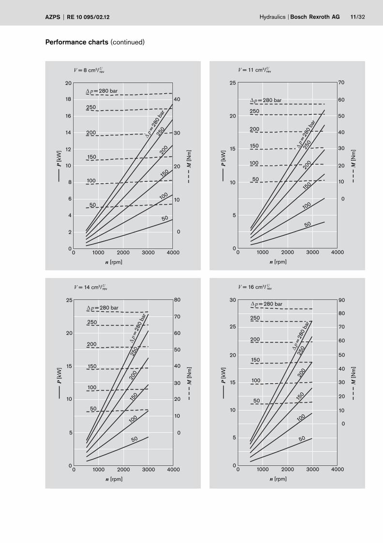
Performance charts (continued)
250
200
150
50
100
250
200
150
100
50
n [rpm]
0 1000 2000 40003000
60
70
50
40
30
20
10
0
25
20
15
10
5
0
p = 280 bar
p =
280 b
ar
P [
kW
]
M [
Nm
]
V = 11 cm3/Urev
250
200
150
50
100
250
200
150
100
50
n [rpm]
0 1000 2000 40003000
70
60
50
40
30
20
10
0
8025
20
15
10
5
0
p = 280 bar
p =
280 b
ar
P [
kW
]
M [
Nm
]
V = 14 cm3/Urev
250
200
150
50
100
250
200
150
100
50
n [rpm]
0 1000 2000 40003000
0
40
30
20
10
20
18
16
14
12
10
8
6
4
2
0
p = 280 bar
p =
280 b
ar
P [
kW
]
M [
Nm
]
V = 8 cm3/Urev
250
200
150
50
100
250
200
150
100
50
n [rpm]
0 1000 2000 40003000
90
80
70
0
10
20
30
40
50
60
30
25
20
15
10
5
0
p = 280 bar
p =
280 b
ar
P [
kW
]
M [
Nm
]
V = 16 cm3/ Urev
12/32 Bosch Rexroth AG Hydraulics AZPS RE 10 095/02.12
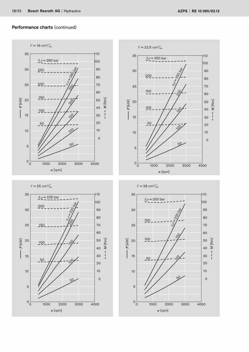
Performance charts (continued)
200
150
50
100
200
150
100
50
n [rpm]
0 1000 2000 4000 3000
90
100
110
80
70
0
10
20
30
40
50
60
35
30
25
20
15
10
5
0
p = 225 bar
p =
225 b
ar
P [
kW
]
M [
Nm
]
V = 25 cm3/ U rev
250
200
150
50
100
200
250
150
100
50
n [rpm]
0 1000 2000 4000 3000
90
100
110
80
70
0
10
20
30
40
50
60
35
30
25
20
15
10
5
0
p = 280 bar
p =
280 b
ar
P [
kW
]
M [
Nm
]
V = 19 cm3/ U rev
150
200
50
100
150
200
100
50
n [rpm]
0 1000 2000 4000 3000
90
110
100
80
70
0
10
20
30
40
50
60
35
25
30
20
15
10
5
0
p = 250 bar
p =
250 b
ar
P [
kW
]
M [
Nm
]
V = 22.5 cm3/U rev
150
50
100 150
100
50
n [rpm]
0 1000 2000 4000 3000
90
100
110
80
70
0
10
20
30
40
50
60
35
30
25
20
15
10
5
0
p = 200 bar
p =
200 b
ar
P [
kW
]
M [
Nm
]
V = 28 cm3/ U rev

Hydraulics Bosch Rexroth AGAZPS RE 10 095/02.12 13/32
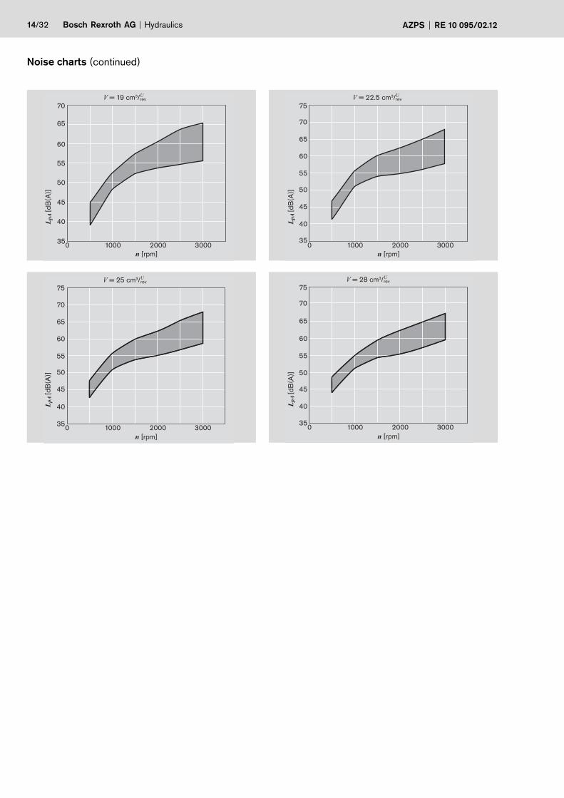
Noise charts
Noise level dependent on rotational speed, pressure range
between 10 bar and pressure value p2 (see page 15 Speci-
fications table).
Oil data: ν = 32 mm2/s, ϑ = 50 °C.
Sound pressure level calculated from noise measurements
made in the sound absorbent measuring room compliant with
DIN 45635, Part 26.
Spacing between measuring sensor – pump: 1 m.
These are typical characteristic values for the respective model.
They describe the airborne sound emitted solely by the pump.
Environmental influences (installation site, piping, further
system components) are not taken into consideration.
Each value applies for a single pump.
1000 0 2000 3000 4000
30
25
35
40
45
50
55
60
n [rpm]
LpA
[d
B(A
)]
V = 4 cm3/ U rev
n [rpm]
LpA
[d
B(A
)]
1000 0 2000 3000 4000
30
25
35
40
45
50
55
60
65 V = 5.5 cm3/U
rev
n [rpm]
LpA
[d
B(A
)]
1000 0 2000 3000 4000 25
30
35
40
45
50
55
60
65 V = 8 cm3/ U
rev
n [rpm]
LpA
[d
B(A
)]
1000 0 2000 3000 4000 30
30
35
40
45
50
55
60
65
V = 11 cm3/ U rev
n [rpm]
LpA
[d
B(A
)]
1000 0 2000 3000 30
35
40
45
50
55
60
65
V = 14 cm3/ U rev
n [rpm]
LpA
[d
B(A
)]
1000 0 2000 3000 30
35
40
45
50
55
60
65
V = 16 cm3/ U rev
14/32 Bosch Rexroth AG Hydraulics AZPS RE 10 095/02.12
Noise charts (continued)
1000 0 2000 3000 35
40
45
50
55
60
65
70
n [rpm]
LpA
[d
B(A
)]
V = 19 cm3/ U rev
n [rpm]
LpA
[d
B(A
)]
1000 0 2000 3000 35
40
45
50
55
60
65
70
75
V = 22.5 cm3/U rev
n [rpm]
LpA
[d
B(A
)]
1000 0 2000 3000 35
40
45
50
55
60
65
70
75 V = 25 cm3/ U
rev
n [rpm]
LpA
[d
B(A
)]
1000 0 2000 3000 35
40
45
50
55
60
65
70
75 V = 28 cm3/ U
rev
Hydraulics Bosch Rexroth AGAZPS RE 10 095/02.12 15/32
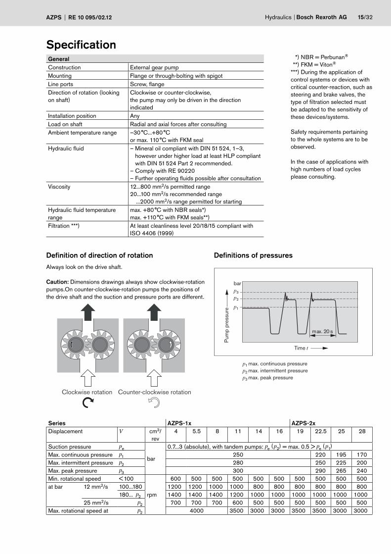
Specification General
Construction External gear pump
Mounting Flange or through-bolting with spigot
Line ports Screw, flange
Direction of rotation (looking
on shaft)
Clockwise or counter-clockwise,
the pump may only be driven in the direction
indicated
Installation position Any
Load on shaft Radial and axial forces after consulting
Ambient temperature range –30 °C...+80 °C
or max. 110 °C with FKM seal
Hydraulic fluid – Mineral oil compliant with DIN 51 524, 1–3,
however under higher load at least HLP compliant
with DIN 51 524 Part 2 recommended.
– Comply with RE 90220
– Further operating fluids possible after consultation
Viscosity 12...800 mm2/s permitted range
20...100 mm2/s recommended range
...2000 mm2/s range permitted for starting
Hydraulic fluid temperature
range
max. +80 °C with NBR seals*)
max. +110 °C with FKM seals**)
Filtration ***) At least cleanliness level 20/18/15 compliant with
ISO 4406 (1999)
*) NBR = Perbunan®
**) FKM = Viton®
***) During the application of
control systems or devices with
critical counter-reaction, such as
steering and brake valves, the
type of filtration selected must
be adapted to the sensitivity of
these devices/systems.
Safety requirements pertaining
to the whole systems are to be
observed.
In the case of applications with
high numbers of load cycles
please consulting.
Definition of direction of rotation
Always look on the drive shaft.
Caution: Dimensions drawings always show clockwise-rotation
pumps.On counter-clockwise-rotation pumps the positions of
the drive shaft and the suction and pressure ports are different.
Definitions of pressures
p3
p2
p1
p1max. continuous pressure
p2max. intermittent pressure
p3max. peak pressure
max. 20 s
Time t
Pum
p p
ressure
bar
Clockwise rotation Counter-clockwise rotation
Series AZPS-1x AZPS-2x
Displacement V cm3/
rev
4 5.5 8 11 14 16 19 22.5 25 28
Suction pressure pe
bar
0.7...3 (absolute), with tandem pumps: pe ( p
2) = max. 0.5 > pe
( p1)
Max. continuous pressure p1 250 220 195 170
Max. intermittent pressure p2 280 250 225 200
Max. peak pressure p3 300 290 265 240
Min. rotational speed < 100
rpm
600 500 500 500 500 500 500 500 500 500
at bar 12 mm2/s 100...180 1200 1200 1000 1000 800 800 800 800 800 800
180... p2 1400 1400 1400 1200 1000 1000 1000 1000 1000 1000
25 mm2/s p2 700 700 700 600 500 500 500 500 500 500
Max. rotational speed at p2 4000 3500 3000 3000 3500 3500 3000 3000
16/32 Bosch Rexroth AG Hydraulics AZPS RE 10 095/02.12
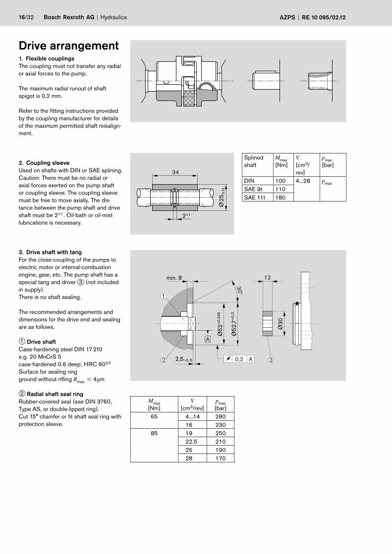
Drive arrangement1. Flexible couplings
The coupling must not transfer any radial
or axial forces to the pump.
The maximum radial runout of shaft
spigot is 0.2 mm.
Refer to the fitting instructions provided
by the coupling manufacturer for details
of the maximum permitted shaft misalign-
ment.
2. Coupling sleeve
Used on shafts with DIN or SAE splining.
Caution: There must be no radial or
axial forces exerted on the pump shaft
or coupling sleeve. The coupling sleeve
must be free to move axially. The dis-
tance between the pump shaft and drive
shaft must be 2+1. Oil-bath or oil-mist
lubrications is necessary.
3. Drive shaft with tang
For the close-coupling of the pumps to
electric motor or internal-combustion
engine, gear, etc. The pump shaft has a
special tang and driver 3 (not included
in supply).
There is no shaft sealing.
The recommended arrangements and
dimensions for the drive end and sealing
are as follows.
1 Drive shaft
Case-hardening steel DIN 17 210
e.g. 20 MnCrS 5
case-hardened 0.6 deep; HRC 60±3
Surface for sealing ring
ground without rifling Rmax.
� 4μm
2 Radial shaft seal ring
Rubber-covered seal (see DIN 3760,
Type AS, or double-lipped ring).
Cut 15° chamfer or fit shaft seal ring with
protection sleeve.
34
2+1
Ø2
5h11
Splined
shaft
Mmax
[Nm]
V
[cm3/
rev]
pmax
[bar]
DIN 100 4...28 pmax
SAE 9t 110
SAE 11t 180
min. 8 12
30°
Ø3
0
Ø5
2+
0,0
46
Ø5
2,7
+0
,3
0,2 A
A
32 2,5–0, 5
1
Mmax
[Nm]
V[cm3/rev]
pmax
[bar]
65 4...14 280
16 230
85 19 250
22.5 210
25 190
28 170
Hydraulics Bosch Rexroth AGAZPS RE 10 095/02.12 17/32
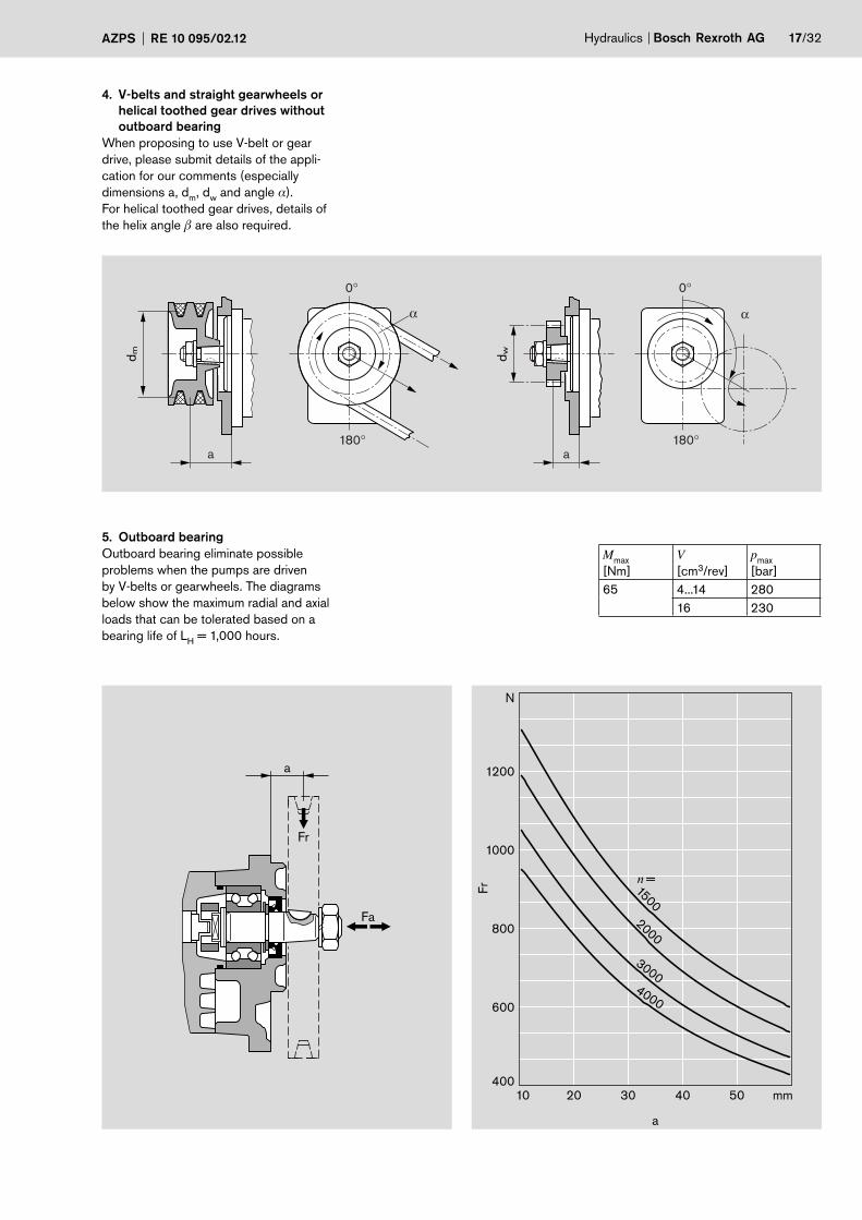
4. V-belts and straight gearwheels or
helical toothed gear drives without
outboard bearing
When proposing to use V-belt or gear
drive, please submit details of the appli-
cation for our comments (especially
dimensions a, dm
, dw and angle α).
For helical toothed gear drives, details of
the helix angle � are also required.
5 . Outboard bearing
Outboard bearing eliminate possible
problems when the pumps are driven
by V-belts or gearwheels. The diagrams
below show the maximum radial and axial
loads that can be tolerated based on a
bearing life of LH = 1,000 hours.
0°
180°
0°
180°
α α
aa
dw
dm
Fr
Fa
a
40010 20 30 40
1500
2000
30004000
50 mm
600
800
1000
1200
N
n =
a
Fr
Mmax
[Nm]
V
[cm3/rev]
pmax
[bar]
65 4...14 280
16 230
18/32 Bosch Rexroth AG Hydraulics AZPS RE 10 095/02.12
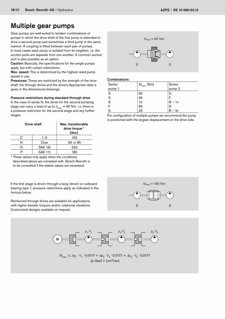
Multiple gear pumpsGear pumps are well-suited to tandem combinations of
pumps in which the drive shaft of the first pump is extended to
drive a second pump and sometimes a third pump in the same
manner. A coupling is fitted between each pair of pumps.
In most cases each pump is isolated from its neighbor, i.e. the
suction ports are separate from one another. A common suction
port is also possible as an option.
Caution: Basically, the specifications for the single pumps
apply, but with certain restrictions:
Max. speed: This is determined by the highest rated pump
speed in use.
Pressures: These are restricted by the strength of the drive
shaft, the through drives and the drivers.Appropriate data is
given in the dimensional drawings.
Pressure restrictions during standard through drive
In the case of series N, the driver for the second pumping
stage can carry a load of up to Smax.
= 95 Nm, i.e. there is
a pressure restriction for the second stage and any further
stages.
Drive shaft Max. transferrable
drive torque *
[Nm]
C 1: 5 155
N Claw 65 or 85
D SAE 13t 320
P SAE 11t 180
* These values only apply when the conditions
described above are complied with. Bosch Rexroth is
to be consulted if the stated values are exceeded.
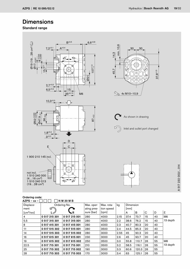
If the first stage is driven through a tang (driver) or outboard
bearing type 1, pressure restrictions apply as indicated in the
formula below.
Reinforced through drives are available for applications
with higher transfer torques and/or rotational vibrations.
Customized designs available on request.
S S
Mmax. = 65 Nm
Combinations
Series
pump 1
Mmax.
[Nm] Series
pump 2
S
S
S
F
S
65
65
12
65
25
S
F
B – 1x
S
B – 2x
For configuration of multiple pumps we recommend the pump
is positioned with the largest displacement on the drive side.
S S
Mmax. = 160 Nm
M
Mmax.
� Δp1 · V
1 · 0.0177 + Δp
2 · V
2 · 0.0177 + Δp
3 · V
3 · 0.0177
Δp [bar] V [cm3/rev]
p1 V
1p
2 V
2p
3 V
3
Hydraulics Bosch Rexroth AGAZPS RE 10 095/02.12 19/32
As shown in drawing
Inlet and outlet port changed
15
35±0,15
36
–0
,5
45° 45°
A±0,4
10
7+
1,5
–1
Ø2
1
87
–0
,2
Ø1
9 (
19
…2
8 c
m3 /
)
–0
,02
58
–0
,08
3
–0
,03
0Ø
52
–0
,07
6
7,2±0,1
B±0,5 6,6±0,8
10,3±0,3
C
45° 45°
D
1,8±0,2
3±0,2
not incl.1 510 240 000 (4…16 cm3)1 510 240 013 (19…28 cm3)
M6
E
15
,7±1
6,5+0,2
2,7+0,5
Ø4
7,9
–0
,1
37
,8±1
,5
min
. 1
0,6
4x M10–10,9
45
,71
4,3
3030
1 900 210 145 incl.
U rev
Ø1
7–
0,0
27
A 5
17
23
2 0
02
/... 0
14
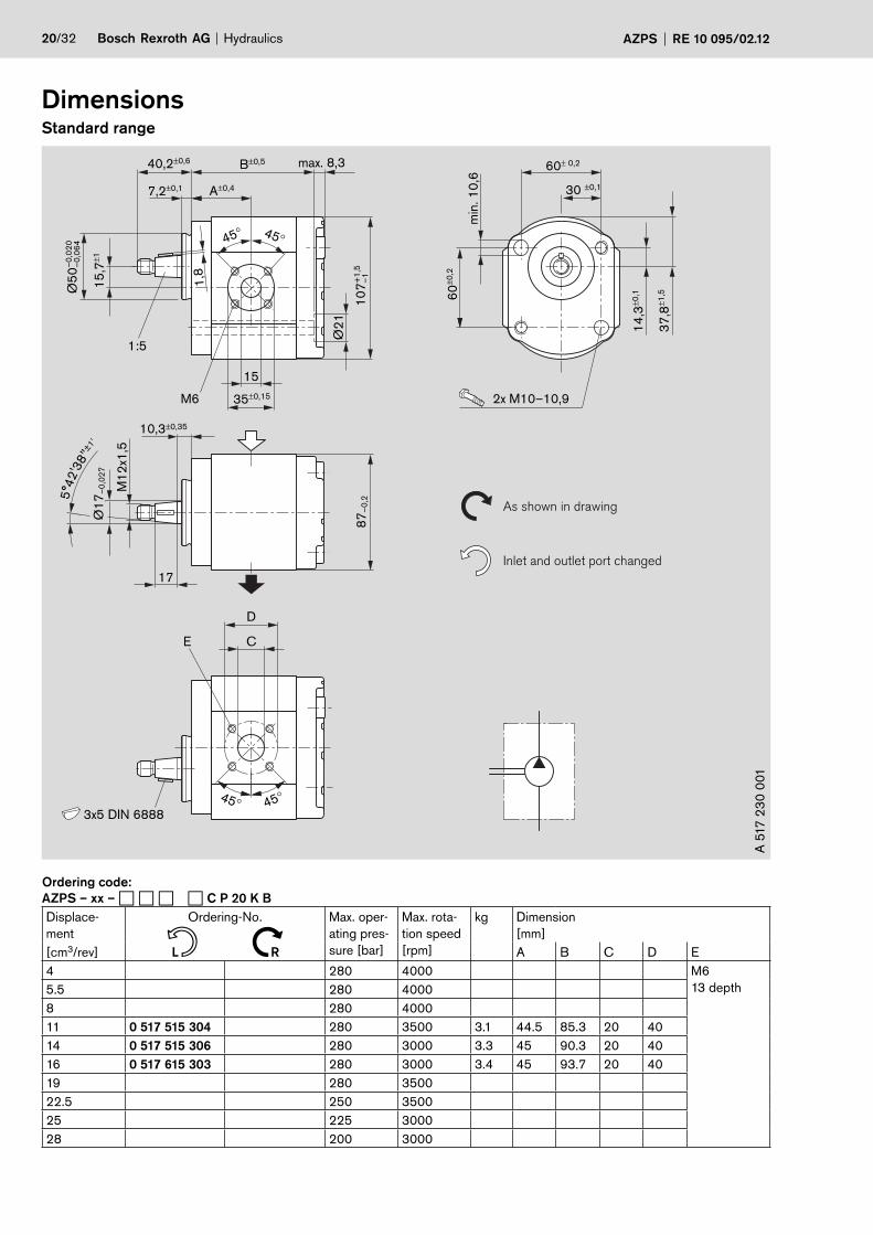
DimensionsStandard range
Ordering code:
AZPS – xx – � � � � N M 20 M B
Displace-
ment
Ordering-No. Max. oper-
ating pres-
sure [bar]
Max. rota-
tion speed
[rpm]
kg Dimension
[mm]
[cm3/rev] L R A B C D E
4 0 517 215 301 0 517 215 001 280 4000 2.15 37.4 73.7 15 40 M6
13 depth5.5 0 517 315 301 0 517 315 001 280 4000 2.2 38.6 76.2 15 40
8 0 517 415 301 0 517 415 001 280 4000 2.3 40.7 80.3 20 40
11 0 517 515 302 0 517 515 001 280 3500 2.4 44.5 85.3 20 40
14 0 517 515 303 0 517 515 002 280 3000 2.55 45 90.3 20 40
16 0 517 615 301 0 517 615 001 230 3000 2.6 45 93.7 20 40
19 0 517 615 302 0 517 615 002 250 3500 3.0 55.8 110.7 26 55 M8
13 depth22.5 0 517 715 301 0 517 715 001 210 3500 3.2 58.5 116.1 26 55
25 0 517 715 302 0 517 715 002 190 3000 3.3 60.6 120.3 26 55
28 0 517 715 303 0 517 715 003 170 3000 3.4 63 125.1 26 55
n N
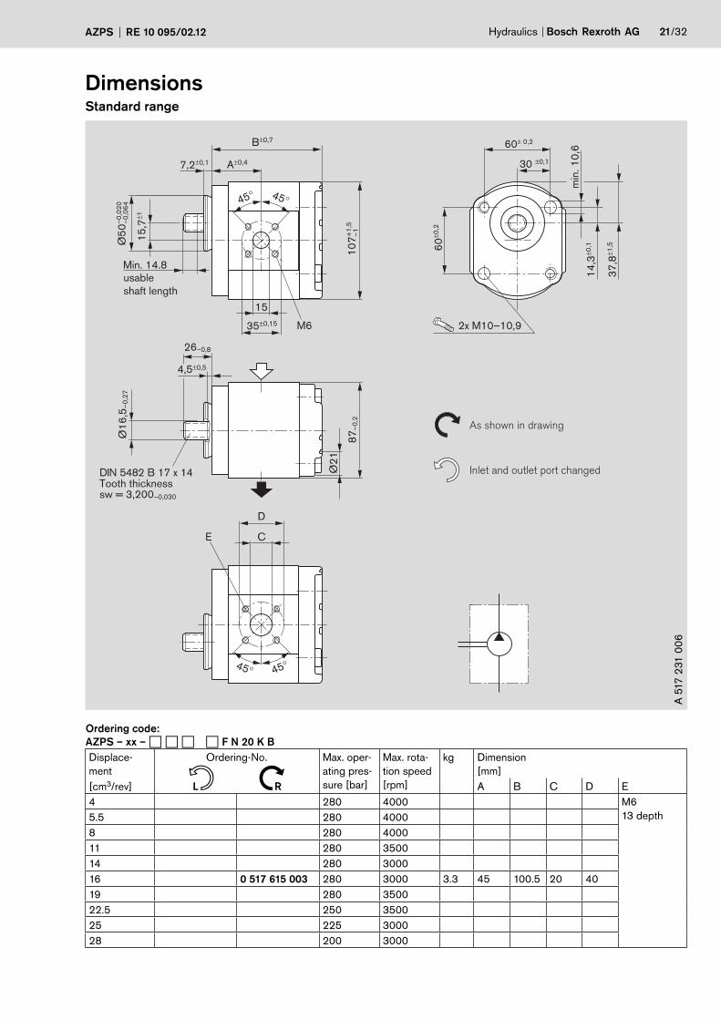
20/32 Bosch Rexroth AG Hydraulics AZPS RE 10 095/02.12
DimensionsStandard range
As shown in drawing
Inlet and outlet port changed
37
,8±1
,5
15
35±0,15
45° 45°
max. 8,3
A±0,4
Ø2
1
Ø1
7–
0,0
27
87
–0
,2
min
. 1
0,6
2x M10–10,9
60
±0,2
60± 0,2
30 ±0,1
14
,3±0
,1
15
,7±1
–0
,02
0Ø
50
–0
,06
4
1,8
40,2±0,6
7,2±0,1
1:5
B±0,5
17
10,3±0,35
C
45° 45°
D
3x5 DIN 6888
M1
2x1
,5
M6
5°4
2'3
8"
±1'
E
10
7+
1,5
–1
A 5
17
23
0 0
01
Ordering code:
AZPS – xx – � � � � C P 20 K B
Displace-
ment
Ordering-No. Max. oper-
ating pres-
sure [bar]
Max. rota-
tion speed
[rpm]
kg Dimension
[mm]
[cm3/rev] L R A B C D E
4 280 4000 M6
13 depth5.5 280 4000
8 280 4000
11 0 517 515 304 280 3500 3.1 44.5 85.3 20 40
14 0 517 515 306 280 3000 3.3 45 90.3 20 40
16 0 517 615 303 280 3000 3.4 45 93.7 20 40
19 280 3500
22.5 250 3500
25 225 3000
28 200 3000
n N
Hydraulics Bosch Rexroth AGAZPS RE 10 095/02.12 21/32
DimensionsStandard range
37
,8±1
,5
15
35±0,15
45° 45°
A±0,4
Ø1
6,5
–0
,27
87
–0
,2
min
. 1
0,6
2x M10–10,9
As shown in drawing
Inlet and outlet port changed
60
±0,2
60± 0,2
30 ±0,1
14
,3±0
,1 1
5,7
±1
26–0,8
7,2±0,1
B±0,7
4,5±0,5
45° 45°
M6
Min. 14.8
usable
shaft length
DIN 5482 B 17 x 14Tooth thickness sw = 3,200–0,030
Ø2
1
–0
,02
0
Ø5
0–
0,0
64
10
7+
1,5
–
1
C
D
E
A 5
17
231
00
6
Ordering code:
AZPS – xx – � � � � F N 20 K B
Displace-
ment
Ordering-No. Max. oper-
ating pres-
sure [bar]
Max. rota-
tion speed
[rpm]
kg Dimension
[mm]
[cm3/rev] L R A B C D E
4 280 4000 M6
13 depth5.5 280 4000
8 280 4000
11 280 3500
14 280 3000
16 0 517 615 003 280 3000 3.3 45 100.5 20 40
19 280 3500
22.5 250 3500
25 225 3000
28 200 3000
n N
22/32 Bosch Rexroth AG Hydraulics AZPS RE 10 095/02.12
DimensionsStandard range
12
0±1
,5
72±0,2
90±1,5
15
35±0,15
45° 45°
A±0,4
Ø1
8
Ø1
7–
0,0
27
12,5–0,4
87
–0
,2
As shown in drawing
Inlet and outlet port changed
10
0±0
,2
34
,5±0
,19
±0,1
1
44
,5±1
,5
15
,7±1
–0
,06
0Ø
80
–0
,10
6
1,8
38±0,6
7,2±0,1
1:5
B±0,7
17
7,8±0,35
C
45° 45°
D
3x5 DIN 6888
DIN 936-M12x1,5-m-06
DIN 128-A12-FSt
M6
= 50+10 NmE
5°4
2'3
8"
±1'
R9±0
,5
10
7+
1,5
–1
A 5
17
24
0 0
02
/... 0
13
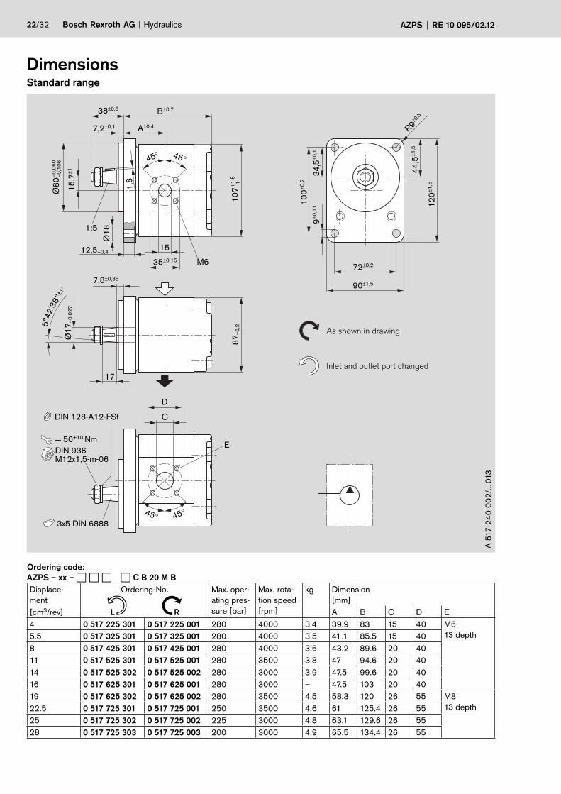
Ordering code:
AZPS – xx – � � � � C B 20 M B
Displace-
ment
Ordering-No. Max. oper-
ating pres-
sure [bar]
Max. rota-
tion speed
[rpm]
kg Dimension
[mm]
[cm3/rev] L R A B C D E
4 0 517 225 301 0 517 225 001 280 4000 3.4 39.9 83 15 40 M6
13 depth5.5 0 517 325 301 0 517 325 001 280 4000 3.5 41.1 85.5 15 40
8 0 517 425 301 0 517 425 001 280 4000 3.6 43.2 89.6 20 40
11 0 517 525 301 0 517 525 001 280 3500 3.8 47 94.6 20 40
14 0 517 525 302 0 517 525 002 280 3000 3.9 47.5 99.6 20 40
16 0 517 625 301 0 517 625 001 280 3000 – 47.5 103 20 40
19 0 517 625 302 0 517 625 002 280 3500 4.5 58.3 120 26 55 M8
13 depth22.5 0 517 725 301 0 517 725 001 250 3500 4.6 61 125.4 26 55
25 0 517 725 302 0 517 725 002 225 3000 4.8 63.1 129.6 26 55
28 0 517 725 303 0 517 725 003 200 3000 4.9 65.5 134.4 26 55
n N
Hydraulics Bosch Rexroth AGAZPS RE 10 095/02.12 23/32
DimensionsStandard range
15
35±0,15
31,5±0,4 12,5–0,5
(7–0,3/Ø18,5)
A±0,4
Ø1
5,4
56
–0
,12
7
Ø1
7–
0,0
27 Ø
21
87
–0
,2 As shown in drawing
Inlet and outlet port changed
32
+2
106,4± 0,15
127± 1,5
11+0,27
R47
±1
15
,7±1
Ø8
2,5
5–
0,0
5
6,2±0,1 B±0,7
8±0,5
C
45° 45°
D
M6
E
Urev
ANSI B 92.1,9T 16/32 SPTooth thickness s = 2,357–0,030
Profile offset –0,087
4/5,5 cm3 /
45° 45°
10
7+
1,5
–1
Min. 21.8
usable
shaft length
A 5
17
241
001/.
.. 0
09
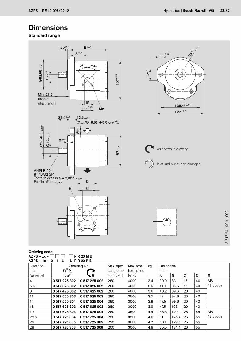
Ordering code:
AZPS – xx – � � � � R R 20 M B
AZPS – 1x – 0 1 6 L R R 20 P B
Displace-
ment
Ordering-No. Max. oper-
ating pres-
sure [bar]
Max. rota-
tion speed
[rpm]
kg Dimension
[mm]
[cm3/rev] L R A B C D E
4 0 517 225 302 0 517 225 002 280 4000 3.4 39.9 83 15 40 M6
13 depth5.5 0 517 325 302 0 517 325 002 280 4000 3.5 41.1 85.5 15 40
8 0 517 425 302 0 517 425 002 280 4000 3.6 43.2 89.6 20 40
11 0 517 525 303 0 517 525 003 280 3500 3.7 47 94.6 20 40
14 0 517 525 304 0 517 525 004 280 3000 3.9 47.5 99.6 20 40
16 0 517 625 303 0 517 625 003 280 3000 3.9 47.5 103 20 40
19 0 517 625 304 0 517 625 004 280 3500 4.4 58.3 120 26 55 M8
13 depth22.5 0 517 725 304 0 517 725 004 250 3500 4.6 61 125.4 26 55
25 0 517 725 305 0 517 725 005 225 3000 4.7 63.1 129.6 26 55
28 0 517 725 306 0 517 725 006 200 3000 4.8 65.5 134.4 26 55
n N
24/32 Bosch Rexroth AG Hydraulics AZPS RE 10 095/02.12
DimensionsStandard range
12,5–0,5
A±0,4
Ø1
5,8
75
–0
,02
5
Ø1
7,7
3–
0,1
3Ø
17
–0
,02
7 Ø2
1
87
–0
,2 As shown in drawing
Inlet and outlet port changed
32
+2
106,4± 0,15
127± 1,5
11+0,27
15
,7±1
Ø8
2,5
5–
0,0
5
6,2±0,1
7,8±0,5
32±0,4
B±0,7
R47
±1
KEY.156 SQ x .750 LG
C
for O-ring sealing
D
for O-ring sealing
10
7+
1,5
–1
A 5
17
24
0 8
01
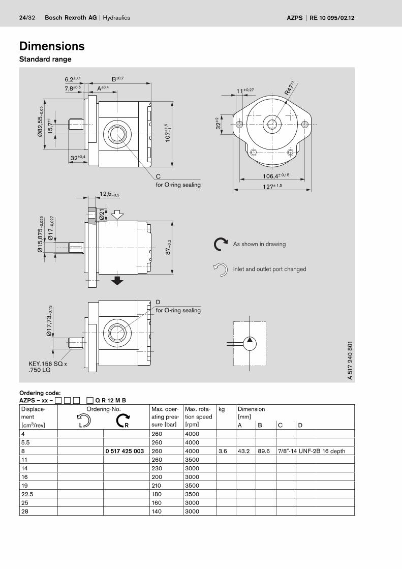
Ordering code:
AZPS – xx – � � � � Q R 12 M B
Displace-
ment
Ordering-No. Max. oper-
ating pres-
sure [bar]
Max. rota-
tion speed
[rpm]
kg Dimension
[mm]
[cm3/rev] L R A B C D
4 260 4000
5.5 260 4000
8 0 517 425 003 260 4000 3.6 43.2 89.6 7/8�-14 UNF-2B 16 depth
11 260 3500
14 230 3000
16 200 3000
19 210 3500
22.5 180 3500
25 160 3000
28 140 3000
n N
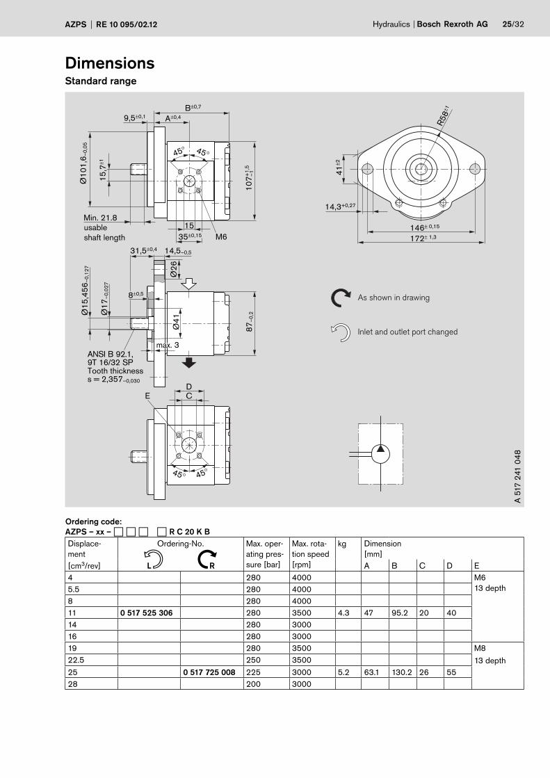
Hydraulics Bosch Rexroth AGAZPS RE 10 095/02.12 25/32
DimensionsStandard range
14,5–0,531,5±0,4
8±0,5
A±0,4
Ø1
5,4
56
–0
,12
7
Ø4
1Ø
26
Ø1
7–
0,0
27
87
–0
,2
41
±2
146± 0,15
14,3+0,27
172± 1,3
15
,7±1
35±0,15
15
Ø1
01
,6–
0,0
5
9,5±0,1
B±0,7
45° 45°
max. 3
M6
C
45° 45°
DE
ANSI B 92.1,9T 16/32 SPTooth thicknesss = 2,357–0,030
R58
±1
10
7+
1,5
–1
As shown in drawing
Inlet and outlet port changed
Min. 21.8
usable
shaft length
A 5
17
241
04
8Ordering code:
AZPS – xx – � � � � R C 20 K B
Displace-
ment
Ordering-No. Max. oper-
ating pres-
sure [bar]
Max. rota-
tion speed
[rpm]
kg Dimension
[mm]
[cm3/rev] L R A B C D E
4 280 4000 M6
13 depth5.5 280 4000
8 280 4000
11 0 517 525 306 280 3500 4.3 47 95.2 20 40
14 280 3000
16 280 3000
19 280 3500 M8
13 depth22.5 250 3500
25 0 517 725 008 225 3000 5.2 63.1 130.2 26 55
28 200 3000
n N
26/32 Bosch Rexroth AG Hydraulics AZPS RE 10 095/02.12
DimensionsStandard range
7,8±0,35
12,5–0,4
17
Ø1
7–
0,0
27
87
–0
,2 As shown in drawing
Inlet and outlet port changed
Ø8
0–
0,0
60
–0
,10
6
B+0,7–1,2
72± 0,2
10
0±
0,2 3
4,5
± 0
,19
± 0
,11
44
,5±
1,5
12
0±
1,5
90± 1,5
15
,7±1
D
C
7,2±0,1
38±0,6 A2
A1
45° 45°
E
45° 45°
15
35±0,15
Ø1
8
1,8
3x5 DIN 6888
1:5
5°4
2'3
8"
±1'
DIN 936-M12x1,5-m-06
DIN 128-A12-FSt
= 50+10 Nm
M6R9
±0,5
10
7+
1,5
–1
A 5
17
24
4 0
07
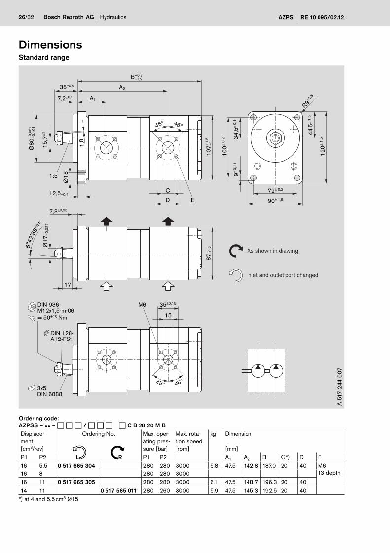
Ordering code:
AZPSS – xx – � � � / � � � � C B 20 20 M B
Displace-
ment
[cm3/rev]
Ordering-No. Max. oper-
ating pres-
sure [bar]
Max. rota-
tion speed
[rpm]
kg Dimension
[mm]
P1 P2 L R P1 P2 A1 A2 B C *) D E
16 5.5 0 517 665 304 280 280 3000 5.8 47.5 142.8 187.0 20 40 M6
13 depth16 8 280 280 3000
16 11 0 517 665 305 280 280 3000 6.1 47.5 148.7 196.3 20 40
14 11 0 517 565 011 280 260 3000 5.9 47.5 145.3 192.5 20 40
*) at 4 and 5.5 cm3 Ø15
n N
Hydraulics Bosch Rexroth AGAZPS RE 10 095/02.12 27/32
DimensionsStandard range
15
35±0,15
31,5±0,4 12,5–0,5
45° 45°
A1±0,4
Ø1
5,4
56
–0
,12
7
Ø1
7–
0,0
27 Ø
21
87
–0
,2
As shown in drawing
Inlet and outlet port changed3
2+
2
106,4± 0,15
127± 1,5
11+0,27
R47
±1
15
,7±1
Ø8
2,5
5–
0,0
5
6,2±0,1
8±0,5
C
45° 45°
D
M6
E
ANSI B 92.1,9T 16/32 SPTooth thickness s = 2,357–0,030
Profile offset –0,087
B+0,7–1,2
A2±1
10
7+
1,5
–1
Min. 21.8
usable
shaft length
A 5
17
24
5 0
03
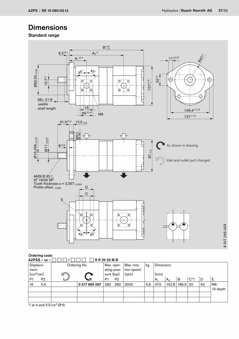
Ordering code:
AZPSS – xx – � � � / � � � � R R 20 20 M B
Displace-
ment
[cm3/rev]
Ordering-No. Max. oper-
ating pres-
sure [bar]
Max. rota-
tion speed
[rpm]
kg Dimension
[mm]
P1 P2 L R P1 P2 A1 A2 B C *) D E
16 5.5 0 517 665 007 280 280 3000 5.8 47.5 142.8 186.9 20 40 M6
13 depth
*) at 4 and 5.5 cm3 Ø15
n N
28/32 Bosch Rexroth AG Hydraulics AZPS RE 10 095/02.12
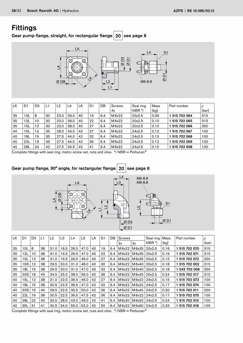
FittingsGear pump flange, straight, for rectangular flange 20 see page 8
Gear pump flange, 90° angle, for rectangular flange 20 see page 8
LAL4 S1
L2
L1
Ø D
3
Ø D
1
Ø D
1
Ø DB LK
LA
M6-8.8
LK D1 D3 L1 L2 L4 LA S1 DB Screws
4x
Seal ring
NBR *)
Mass
[kg]
Part number p[bar]
35 10L 8 30 23.0 39.0 40 19 6.4 M 6x22 20x2.5 0.09 1 515 702 064 315
35 12L 10 30 23.0 39.0 40 22 6.4 M 6x22 20x2.5 0.10 1 515 702 065 315
35 15L 12 30 23.0 38.0 40 27 6.4 M 6x22 20x2.5 0.10 1 515 702 066 250
40 15L 12 35 28.0 43.0 42 27 6.4 M 6x22 24x2.5 0.12 1 515 702 067 100
40 18L 15 35 27.5 44.0 42 32 6.4 M 6x22 24x2.5 0.13 1 515 702 068 100
40 22L 19 35 27.5 44.5 42 36 6.4 M 6x22 24x2.5 0.12 1 515 702 069 100
40 28L 24 42 27.5 34.5 42 41 6.4 M 6x22 24x2.5 0.15 1 515 702 008 100
Complete fittings with seal ring, metric screw set, nuts and olive. *) NBR = Perbunan®
LK D1 D3 L1 L2 L3 L4 L5 LA S1 DB Screws Seal ring
NBR *)
Mass
[kg]
Part number p(bar)2x 2x
35 10L 8 38 31.0 16.5 26.5 47.0 40 19 6.4 M 6x22 M 6x35 20x2.5 0.16 1 515 702 070 315
35 12L 10 38 31.0 16.5 26.5 47.0 40 22 6.4 M 6x22 M 6x35 20x2.5 0.16 1 515 702 071 315
35 15L 12 38 31.0 16.5 26.5 46.0 40 27 6.4 M 6x22 M 6x35 20x2.5 0.15 1 515 702 072 250
35 16S 12 38 29.5 20.0 31.0 48.0 40 30 6.4 M 6x22 M 6x40 20x2.5 0.18 1 515 702 002 315
35 18L 15 38 29.5 20.0 31.0 47.0 40 32 6.4 M 6x22 M 6x40 20x2.5 0.18 1 545 702 006 250
35 20S 16 45 34.5 25.0 38.0 56.0 40 36 6.4 M 6x22 M 6x45 20x2.5 0.24 1 515 702 017 315
40 15L 12 38 31.0 22.5 36.5 46.0 42 27 6.4 M 6x22 M 6x22 24x2.5 0.15 1 515 702 073 100
40 18L 15 38 30.5 22.5 36.5 47.0 42 32 6.4 M 6x22 M 6x22 24x2.5 0.17 1 515 702 074 100
40 20S 16 40 29.5 22.5 35.5 50.0 42 36 6.4 M 6x22 M 6x45 24x2.5 0.20 1 515 702 011 250
40 22L 19 38 30.5 22.5 36.5 47.5 42 36 6.4 M 6x22 M 6x22 24x2.5 0.17 1 515 702 075 100
40 28L 22 40 32.5 28.0 43.0 49.0 42 41 6.4 M 6x20 M 6x50 24x2.5 0.24 1 515 702 010 100
40 35L 31 41 30.5 34.0 55.0 52.0 42 50 6.4 M 6x22 M 6x60 24x2.5 0.33 1 515 702 018 100
Complete fittings with seal ring, metric screw set, nuts and olive. *) NBR = Perbunan®
M6-8.8 M8-8.8 LA
S1
L2L1
L3
L4
L5
Ø D3
Ø D1
Ø D1
LK
Ø D
BLA
Hydraulics Bosch Rexroth AGAZPS RE 10 095/02.12 29/32
Gear pump flange, 3-hole, 90° angle, for rectangular flange 30 see page 8
LK D1 D3 L1 L2 L3 L4 L5 LA S1 DB Screws
3x
Seal ring
NBR *)
Mass
[kg]
Part number p[bar]
30 12L 10 37 30.0 10 37.5 46 38 22 6.4 M 6x22 16x2.5 0.13 1 515 702 146 250
30 15L 12 37 30.0 10 37.5 47 38 27 6.4 M 6x22 16x2.5 0.14 1 515 702 147 250
30 18L 15 37 30.0 10 37.5 47 38 32 6.4 M 6x22 16x2.5 0.17 1 515 702 148 160
40 22L 19 43 35.5 14 41.0 53 48 36 8.4 M 8x30 24x2.5 0.29 1 515 702 149 160
40 28L 24 43 35.5 14 41.0 53 48 41 8.4 M 8x30 24x2.5 0.40 1 515 702 150 160
Complete fittings with seal ring, metric screw set, nuts and olive. *) NBR = Perbunan®
M6-8.8M8-8.8LK
LA
Ø D3
Ø D1 S1
L3
L4
L5
L1L2
Ø D
B
Ordering-No.
Ordering-No. Page
0 517 215 001 19
0 517 215 301 19
0 517 225 001 22
0 517 225 002 23
0 517 225 301 22
0 517 225 302 23
0 517 315 001 19
0 517 315 301 19
0 517 325 001 22
0 517 325 002 23
0 517 325 301 22
0 517 325 302 23
0 517 415 001 19
0 517 415 301 19
0 517 425 001 22
0 517 425 002 23
0 517 425 003 24
0 517 425 301 22
0 517 425 302 23
0 517 515 001 19
0 517 515 002 19
0 517 515 302 19
0 517 515 303 19
0 517 515 304 20
Ordering-No. Page
0 517 515 306 20
0 517 525 001 22
0 517 525 002 22
0 517 525 003 23
0 517 525 004 23
0 517 525 301 22
0 517 525 302 22
0 517 525 303 23
0 517 525 304 23
0 517 525 306 25
0 517 565 011 26
0 517 615 001 19
0 517 615 002 19
0 517 615 003 21
0 517 615 301 19
0 517 615 303 19
0 517 615 303 20
0 517 625 001 22
0 517 625 002 22
0 517 625 003 23
0 517 625 004 23
0 517 625 301 22
0 517 625 302 22
0 517 625 303 23
Ordering-No. Page
0 517 625 304 23
0 517 665 007 27
0 517 665 304 26
0 517 665 305 26
0 517 715 001 19
0 517 715 002 19
0 517 715 003 19
0 517 715 301 19
0 517 715 302 19
0 517 715 303 19
0 517 725 001 22
0 517 725 002 22
0 517 725 003 22
0 517 725 004 23
0 517 725 005 23
0 517 725 006 23
0 517 725 008 25
0 517 725 301 22
0 517 725 302 22
0 517 725 303 22
0 517 725 304 23
0 517 725 305 23
0 517 725 306 23
Note
You can find the permissible tightening torques in our publication:
“General Operating Instructions for External Gear Units”
RE 07 012-B1.
30/32 Bosch Rexroth AG Hydraulics AZPS RE 10 095/02.12
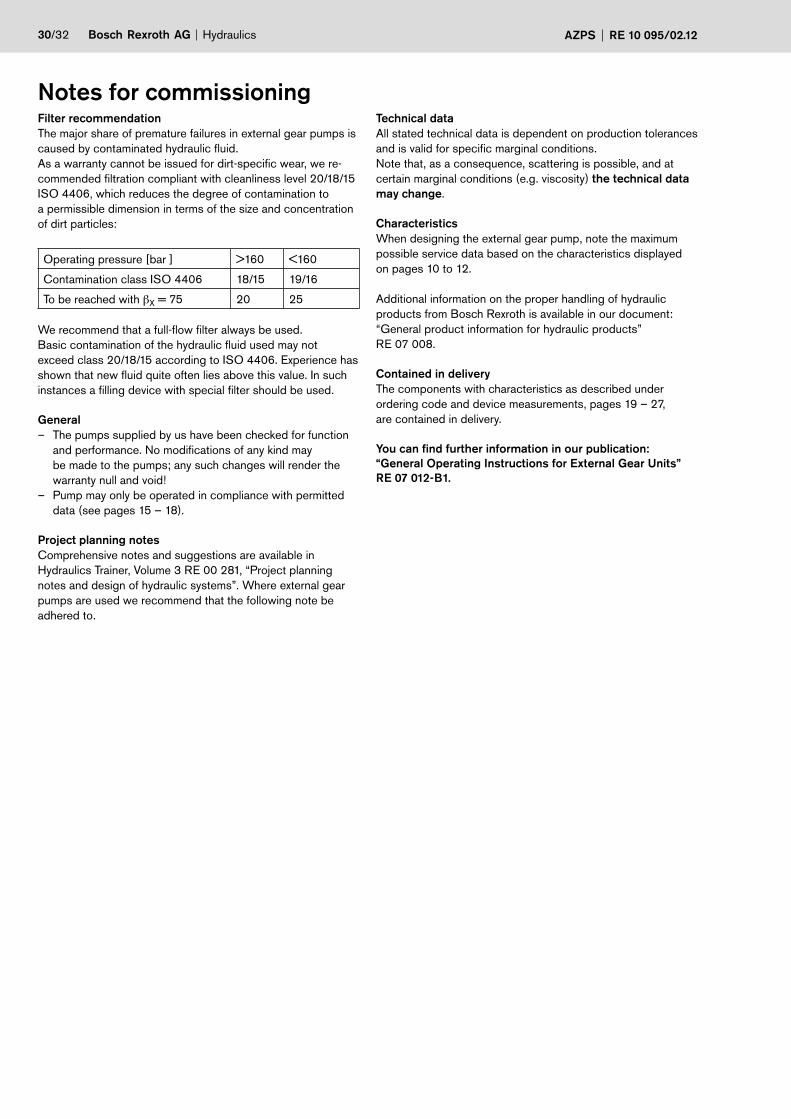
Notes for commissioningFilter recommendation
The major share of premature failures in external gear pumps is
caused by contaminated hydraulic fluid.
As a warranty cannot be issued for dirt-specific wear, we re-
commended filtration compliant with cleanliness level 20/18/15
ISO 4406, which reduces the degree of contamination to
a permissible dimension in terms of the size and concentration
of dirt particles:
Operating pressure [bar ] >160 <160
Contamination class ISO 4406 18/15 19/16
To be reached with βX = 75 20 25
We recommend that a full-flow filter always be used.
Basic contamination of the hydraulic fluid used may not
exceed class 20/18/15 according to ISO 4406. Experience has
shown that new fluid quite often lies above this value. In such
instances a filling device with special filter should be used.
General
– The pumps supplied by us have been checked for function
and performance. No modifications of any kind may
be made to the pumps; any such changes will render the
warranty null and void!
– Pump may only be operated in compliance with permitted
data (see pages 15 – 18).
Project planning notes
Comprehensive notes and suggestions are available in
Hydraulics Trainer, Volume 3 RE 00 281, “Project planning
notes and design of hydraulic systems”. Where external gear
pumps are used we recommend that the following note be
adhered to.
Technical data
All stated technical data is dependent on production toler ances
and is valid for specific marginal conditions.
Note that, as a consequence, scattering is possible, and at
certain marginal conditions (e.g. viscosity) the technical data
may change.
Characteristics
When designing the external gear pump, note the maximum
possible service data based on the characteristics displayed
on pages 10 to 12.
Additional information on the proper handling of hydraulic
products from Bosch Rexroth is available in our document:
“General product information for hydraulic products”
RE 07 008.
Contained in delivery
The components with characteristics as described under
ordering code and device measurements, pages 19 – 27,
are contained in delivery.
You can find further information in our publication:
“General Operating Instructions for External Gear Units”
RE 07 012-B1.
Hydraulics Bosch Rexroth AGAZPS RE 10 095/02.12 31/32
Page Ordering code Seal kit
Pos. 800
1 517 010 ...
Shaft seal ring
Pos. 3
1 510 283 ...
Dimension Seal ring
Pos. 31
1 900 210 ...
Material Dimen-
sion
Driver
Pos. 30
1 510 240 ...
19 AZPS – 1x – � � � � N M 20 M B 208 – 145 NBR 45x2.5 000
19 AZPS – 2x – � � � � N M 20 K B 212 – 145 NBR 45x2.5 013
20 AZPS – 1x – � � � � C P 20 K B 208 027 FKM 17x30x7/8 – – –
21 AZPS – 1x – � � � � F N 20 K B 208 027 FKM 17x30x7/8 – – –
22 AZPS – 1x – � � � � C B 20 M B 208 008 NBR 17x30x7/8 – – –
22 AZPS – 2x – � � � � C B 20 M B 212 008 NBR 17x30x7/8 – – –
23 AZPS – 1x – � � � � R R 20 M B 208 008 NBR 17x30x7/8 – – –
23 AZPS – 1x – 0 1 6 L R R 20 P B 206 027 FKM 17x30x7/8 – – –
23 AZPS – 2x – � � � � R R 20 M B 212 008 NBR 17x30x7/8 – – –
24 AZPS – 1x – � � � � Q R 12 M B 208 008 NBR 17x30x7/8 – – –
25 AZPS – 1x – � � � � R C 20 K B 208 027 FKM 17x30x7/8 – – –
25 AZPS – 2x – � � � � R C 20 K B 212 027 FKM 17x30x7/8 – – –
26 AZPSS – 1x – � � � � � � � C B 20 20 M B 208 008 NBR 17x30x7/8 145 NBR 45x2.5 –
27 AZPSS – 1x – � � � � � � � R R 20 20 M B 208 008 NBR 17x30x7/8 145 NBR 45x2.5 –
NBR = Perbunan® FKM = Viton®
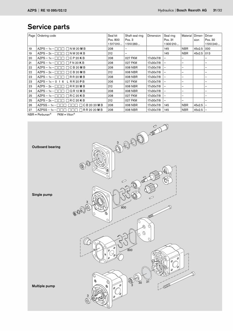
3
3
3
800
330 31
800
Outboard bearing
Multiple pump
Single pump
Service parts
Bosch Rexroth AG
External Gear Units
Robert-Bosch-Straße 2
D-71701 Schwieberdingen
Phone +49 (0) 711-811 10 63
Fax +49 (0) 711-811 17 98
www.boschrexroth.com/brm
© This document, as well as the data, specifications and other information
set forth in it, are the exclusive property of Bosch Rexroth AG. It may not
be reproduced or given to third parties without its consent.
The data specified above only serve to describe the product. No state-
ments concerning a certain condition or suitability for a certain application
can be derived from our information. The information given does not release
the user from the obligation of own judgement and verification. It must be
remembered that our products are subject to a natural process of wear and
aging.
32/32 Bosch Rexroth AG Hydraulics AZPS RE 10 095/02.12
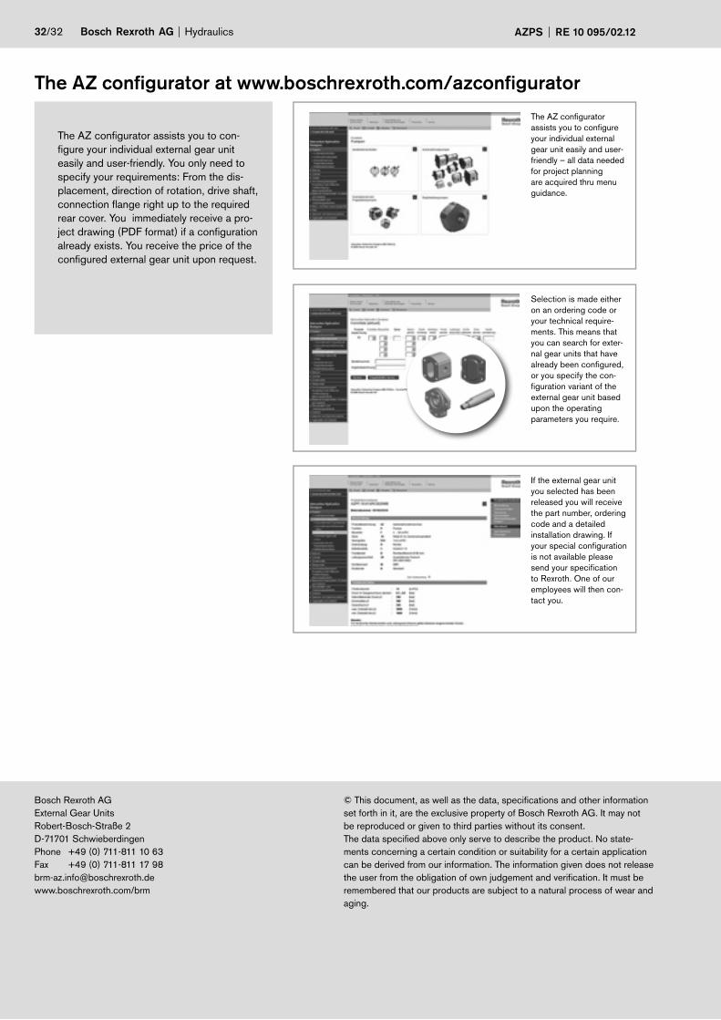
The AZ configurator at www.boschrexroth.com/azconfigurator
The AZ configurator assists you to con-
figure your individual external gear unit
easily and user-friendly. You only need to
specify your requirements: From the dis-
placement, direction of rotation, drive shaft,
connection flange right up to the required
rear cover. You immediately receive a pro-
ject drawing (PDF format) if a configuration
already exists. You receive the price of the
configured external gear unit upon request.
The AZ configurator
assists you to configure
your individual external
gear unit easily and user-
friendly – all data needed
for project planning
are acquired thru menu
guidance.
Selection is made either
on an ordering code or
your technical require-
ments. This means that
you can search for exter-
nal gear units that have
already been configured,
or you specify the con-
figuration variant of the
external gear unit based
upon the operating
parameters you require.
If the external gear unit
you selected has been
released you will receive
the part number, ordering
code and a detailed
installation drawing. If
your special configuration
is not available please
send your specification
to Rexroth. One of our
employees will then con-
tact you.
Recommended


![[Shinobi] Claymore 095](https://img.pdfslide.us/doc/110x75/568bd68f1a28ab20349c8aa9/shinobi-claymore-095.jpg)