COMPUTER ANIMATION AND VIRTUAL WORLDSComp. Anim. Virtual Worlds 2016; 27:35–57
Published online 2 February 2015 in Wiley Online Library (wileyonlinelibrary.com). DOI: 10.1002/cav.1630
RESEARCH ARTICLE
Extending FABRIK with model constraintsAndreas Aristidou1*, Yiorgos Chrysanthou1 and Joan Lasenby2
1 Department of Computer Science, University of Cyprus, Nicosia, 1678, Cyprus2 Department of Engineering, University of Cambridge, Cambridge, CB2 1PZ, UK
ABSTRACT
Forward and Backward Reaching Inverse Kinematics (FABRIK) is a recent iterative inverse kinematics solver that becamevery popular because of its simplicity, convergence speed and control performance, especially in models with multiple endeffectors. In this paper, we extend and/or adjust FABRIK to be used in problems with leaf joints and closed-loop chains andto control a fixed inter-joint distance in a kinetic chain with unsteady data. In addition, we provide optimisation solutionswhen the target is unreachable and a proof of convergence when a solution is available. We also present various techniquesfor constraining anthropometric and robotic joint models using FABRIK and provide clarifications and solutions to manyquestions raised since the first publication of FABRIK. Finally, a human-like model that has been structured hierarchicallyand sequentially using FABRIK is presented, utilising most of the suggested joint models; it can efficiently trace targets inreal time, without oscillations or discontinuities, verifying the effectiveness of FABRIK. Copyright © 2015 John Wiley &Sons, Ltd.
KEYWORDS
animation; FABRIK; human modelling; inverse kinematics; joint configuration
Supporting information may be found in the online version of this article.
*Correspondence
Andreas Aristidou, Department of Computer Science, University of Cyprus, Nicosia, 1678, Cyprus.E-mail: [email protected]
1. INTRODUCTION
The production of realistic and plausible motions hasbeen a long-standing problem for scholars in many fields,including robotics technology and computer graphics.During recent decades, several approaches have beenimplemented for solving the inverse kinematics (IK) prob-lem; IK is a method for computing the skeletal configu-ration of a figure via estimating each individual degree offreedom (DoF) in order to satisfy a given task. IK findsapplications in many areas where the animation and/orcontrol of different virtual creatures is necessary. IK meth-ods are also frequently used in the video games industryand in the field of computer-aided ergonomics, especiallyin human model development and for simulation pur-poses. However, most of the currently available IK solversseem to have drawbacks, such as erratic discontinuitiesand singularities. They also suffer from unnatural poses,have difficulties in dealing with complex figures and arecomputationally expensive.
Forward and Backward Reaching IK (FABRIK) [1] isa recent, iterative algorithm that uses points and lines tosolve the IK problem. It divides the problem into two
relevant phases, a forward step and a backward step, andsupports all the rotational joint limits and joint orientationsby re-positioning and re-orienting the target at each step.It does not suffer from singularity problems and producessmooth motion without discontinuities. The main advan-tages of the FABRIK approach are its simplicity, the easewith which it can be fit into various models, the support ofdirect optimisations and its ability to control multiple endeffectors, making it ideal for applications in systems thatrequire real-time computation.
In this paper, we present various extensions of theFABRIK algorithm, thus demonstrating its effectiveusage in real-world scenarios. An assortment of differ-ent anthropometric and robotic joint models has beenconstructed, incorporating manipulator constraints. More-over, a variety of different solutions using adjustments ofFABRIK are presented, solving the IK problem in caseswith multiple end effectors, in cases where the ‘end effec-tor’ is not positioned at the end of the chain (leaf joints)and in cases where the chain is in a closed-loop form. Thealgorithm has also been modified to ensure fixed distancesunder noisy or unsteady data. In addition, some minorproblems that have been raised since the first publication
Copyright © 2015 John Wiley & Sons, Ltd. 35

Extending FABRIK with model constraints A. Aristidou, Y. Chrysanthou and J. Lasenby
of the algorithm are clarified, and solutions are clearlydescribed. We also indicate when the targets are reachableor not for cases of single or multiple end effector, providingoptimisation solutions that can save an important amountof computational time. We also provide a proof for theconvergence of the unconstrained version of FABRIK, ifthere is a solution available. Finally, the proposed joint andmodel constraints have been incorporated in a human-likemodel for evaluation purposes; the human-like model hasbeen structured hierarchically, while each individual kine-matic chain is solved sequentially using the constrainedsolutions proposed in this paper, so as to enable tracking ofmultiple targets.
2. LITERATURE REVIEW
2.1. Inverse Kinematics
The solutions to the IK problem can be classified asbelonging to one of six main categories, the analytical,Jacobian, Newton, statistical, data-driven and heuristicmethods. Analytical methods, such as those in [2–5], findall possible solutions as a function of the lengths of themechanism, its starting posture and the rotation constraints.The analytical methods are mainly used in robotics in orderto solve the IK problem of an anthropometric arm and leg.The analytical IK solutions have no singularity problems,they offer a global solution and they are fast, simple andreliable; however, the non-linear nature of the kinematicequations makes them not suitable for redundant systemswith more than 7 DoFs.
The Jacobian solutions are linear approximationsof the IK problem; they linearly model the end effectors’movements relative to instantaneous system changes inlink translation and joint angle. Several different method-ologies have been presented for calculating or approximat-ing the Jacobian inverse, such as the Jacobian transpose,singular value decomposition, damped least squares, selec-tively damped least squares and several extensions [6–11].Jacobian inverse solutions produce smooth postures;however, most of these approaches suffer from high com-putational cost, complex matrix calculations and singular-ity problems. Recently, Kenwright proposed an approachthat solves the IK problem using the Gauss–Seideliterative approximation method [12] that does not sufferfrom singularity problems.
Another family of IK solvers is based on Newton meth-ods. These algorithms seek target configurations that areposed as solutions to a minimisation problem; hence, theyreturn smooth motion without erratic discontinuities. Themost well-known methods are Broyden’s method, Powell’smethod and the Broyden, Fletcher, Goldfarb and Shannomethod [13]. However, the Newton methods are complex,are difficult to implement and have a high computationalcost per iteration.
Recently, some papers have been introduced that solvethe IK problem from a statistical point of view. Courty and
Arnaud [14] proposed a sequential Monte Carlo methodto incorporate kinematic constraints. Hecker et al. [15]utilised an iterative IK solver (particle IK) with variousparameters for tuning the character skeleton behaviourboth statically and dynamically. Neither method suffersfrom matrix singularity problems, and both perform rea-sonably well. An alternative approach is given by Pechevin [16] where the problem is solved from a control perspec-tive; this approach is computationally efficient and does notsuffer from singularity problems.
Data-driven methods use pre-learned postures to solvethe IK problem, via methods that are based on neural netsand artificial intelligence. For instance, Grochow et al.[17] presented a style-based IK method that is based on alearned model of human poses. Given a set of constraints,the proposed system was able to produce, in real time,the most likely pose satisfying those constraints. Anotheralternative approach to the style-based IK was proposed byWu et al. [18], named NAT-IK; instead of using continuousposes, they used discrete poses in order to add robustness tothe IK solver. Wei et al. [19] have presented a data-drivenalgorithm for interactive posing of 3D human charactersfor large training motion database, while Ho et al. [20]proposed a data-driven framework that conserves the topol-ogy of the synthesising postures; using a Gauss linkingintegral, they create realistic human control, while avoid-ing body part penetration by distinguishing topologicallydifferent postures. Sumner et al. [21], and later Der et al.[22], proposed mesh-based IK solvers that learn the spaceof shapes from example meshes. Nevertheless, this fam-ily of methods produces poses that require a pre-learningphase and are highly dependent on the training data.
Finally, the heuristic methods are the simplest andfastest IK solvers. A very popular solution is the cycliccoordinate descent (CCD) method, first introduced byWang and Chen [23]. CCD has a low computational costfor each joint per iteration and can solve the IK problemwithout matrix manipulations. However, CCD can sufferfrom unrealistic animation, even if manipulator constraintshave been added. It is designed to handle serial chains;thus, it is difficult to extend to problems with multipleend effectors or target positions for internal joints. Never-theless, there are several extensions of the CCD algorithmthat deal with the production of unrealistic postures, suchas the one proposed by Kulpa and Multon [24]. Thetriangulation algorithm [25] is another heuristic solver thatuses the cosine rule to calculate each joint angle, start-ing at the root of the kinematic chain and moving outwardtowards the end effector. Although it can reach the targetin just one iteration, having low computational cost, itsresults are often visually unnatural; it can only be appliedto problems with a single end effector and does not supportimposed joint limits. An improved version is given in [26]where the n-link IK problem is reduced to a two-link prob-lem in which each link is rotated at most once in an attemptto reach the target position. A more detailed overview ofIK techniques is given in [27].
36 Comp. Anim. Virtual Worlds 2016; 27:35–57 © 2015 John Wiley & Sons, Ltd.DOI: 10.1002/cav

A. Aristidou, Y. Chrysanthou and J. Lasenby Extending FABRIK with model constraints
2.2. Forward and Backward ReachingInverse Kinematics
In this paper, we discuss and extend the FABRIK algo-rithm; FABRIK is a recent, real-time IK solver that returnssmooth postures in an iterative fashion. Instead of usingangle rotations, FABRIK treats finding the joint locationsas a problem of finding a point on a line; the algorithmtraces back step by step to different positions of the jointof a chain, crossing the chain and back in a finite num-ber of iterations. Although FABRIK is a recent algorithm,it has become a popular IK solver; many researchers andgame developers have implemented or extended FABRIKbecause of its efficiency and simplicity. The latter is whyit is most suitable for being applied on top of animation,when the pose becomes rewritten in each frame. Forinstance, FABRIK has been used for hand skeleton recon-struction [28,29] and for skeletal control under markerocclusion in motion capture (mocap) technology [30].Poddighe and Roos [31] used FABRIK to enable a NAOhumanoid robot to play tic-tac-toe, while they showthat FABRIK outperforms methods that use the Jacobianinverse on all aspects; they also conclude that it is theonly method from the tested algorithms that always yieldsresults with the error tolerance set to zero and is wellbalanced near singularities. Moreover, Liu implementedFABRIK for robot manipulation [32] and Munshi for robotsimulation [33], while Lo and Xie [34] used FABRIK ina redundant four-revolute (4R) spherical wrist mechanismfor an active shoulder exoskeleton. Recently, Hwang andChoi [35] exploited the advantages of FABRIK to manipu-late multiple chains and used it to estimate the root joint ofsmall-articulated animals. In addition, different variationsof FABRIK are currently available; Ramachandran andJohn [36] solve the IK problem using an alternative versionof FABRIK with an intersection of circles, while Naouret al. [37] uses FABRIK within a global iterative optimisa-tion process. Furthermore, Huang and Pelachaud [38] use avariation of FABRIK in order to solve the IK problem froman energy transfer perspective. They used a mass–springmodel to adjust the joint positions by minimising theforce energy that is conserved in springs. Recently, Moyaand Colloud, in [39], proved that FABRIK can cope withtarget priorities, adjusting the initial algorithm to deal withjoints that have more than two segments. Bentrah et al. [40]propose an extension of FABRIK to handle environmentalobstacles and conflicts between tasks. The flexibility of thealgorithm to be easily adapted into different problems, itseasy configuration, its low computational cost and the itsperformance in closed loops or problems with multiple endeffectors make FABRIK a popular and efficient IK solver.
2.3. Joint and Model Constraints
Several biomechanically and anatomically correct modelsthat formalise the range of motion of an articulated figurehave been presented. Joint and model constraints aremainly characterised by the number of parameters that
describe the motion space and are hierarchically structured.For instance, Blow [41] proposes a loop hung in space,limiting the range of motion of the bone to ‘reach windows’described by star polygons. Wilhelms and Van Gelder [42]presented a 3D ‘reach cone’ methodology using planes,treating the joint limits in the same way as in [41].Korein in [2] and Baerlocher and Boulic in [43] parame-terise realistic joint boundaries of the ball-and-socket jointby decomposing the arbitrary orientation into two compo-nents and controlling the rotational joint limits so that theydo not exceed their bounds. Once a proper parametrisa-tion is defined for each joint of the articulated body, ananimation engine is utilised. Tolani et al. [4] presentedanalytical and numerical constraints suitable for anthro-pomorphic limbs; they treat the limbs of 3D charactersindependently in closed form, resulting in fast analyticalsolutions. However, analytic solutions, in general, lackflexibility for under-constrained instances. A pin-and-draginterface for articulated characters is presented by Yamaneand Nakamura [44], where multiple-priority-level archi-tectures for combining end effector and centre of massposition control are illustrated.
Model restrictions, because of their complex nature, aresimplified or approximated by more than one joint. Themost well-known models are the following: the shouldermodel, a complex model composed of three different joints[45–48]; the spine model, a complex arrangement of 24vertebrae (usually, for simplicity, the spine is modelled asa simple chain of joints [2,49–51]); the hand model, whichis the most versatile part of the body comprising a largenumber of joints [52–54]; and the strength model, whichtakes account of the forces applied from the skeletalmuscles to the bones [49].
3. CONVERGENCE PROOF
In this section, we study the articulated system and indicatewhether a target is reachable or not; if the target is unreach-able, we provide optimisation solutions that return the finalpose in just one iteration. In addition, we present a proof ofconvergence when there is a solution available.
The definitions of the terms articulated body, links,joints, kinematic chain and end effector, as well as theirinter-connection, are as described in the original FABRIKpaper [1].
3.1. Reachable and Non-reachable Targets
Even in the simple IK problem, where no movementconstraint exists, the target is not always reachable becauseof the chain configuration and the target location. Thus,it is very important to check whether the target is withinreach or not; the step to identify the conditions that causea target position to be unreachable is easy to implement,especially for cases where no rotational or orientationrestrictions exist, and can importantly lead to a large savingin processing time.
Comp. Anim. Virtual Worlds 2016; 27:35–57 © 2015 John Wiley & Sons, Ltd. 37DOI: 10.1002/cav

Extending FABRIK with model constraints A. Aristidou, Y. Chrysanthou and J. Lasenby
Assume pi is the position of the i-th joint of the kine-matic chain, where i D 1, : : : , n. The reachability checkproceeds as follows: find the distance between the root andthe target, d, and if this distance is smaller than the totalsum of all the inter-joint distances, d <
Pn�1iD1 di, where
di D jpiC1 � pij, for i D 1, : : : , n � 1, and pi is theposition of the i-th joint of the kinematic chain, the targetis within reach; otherwise, it is unreachable. In the casewhere the target is within the feasible bounds, the FABRIKalgorithm is applied normally; otherwise, the solution willbe the direct construction of a line pointing towards thetarget, while keeping the inter-joint distances constant.This can be performed by applying only the backward stepof the algorithm, starting from the root joint, and instead ofusing the joint positions as the intermediate targets at everystep, using the target position. The final pose will be struc-tured in just one iteration. In addition, there are cases wherethe kinematic chain cannot bend enough to reach the target,even if the latter is within the reachable bounds. Such acase occurs when the kinematic chain consists of a linkwith size dmax that is larger than the sum of all the remain-ing links dmax >
Pn�1iD1 di � dmax and the target is located
in a distance d < 2dmax�Pn�1
iD1 di; this is more obvious inFigure 1(a), where a solution cannot be formed if the targetis outside the circle with centre pi radius dist.
Thus, in order to avoid cases where the iterative processenters an endless loop, even though we may neverencounter experimentally such a situation, it is advisableto add termination conditions: the first termination condi-tion would be to compare the position of the end effectorat the previous and current iterations, and if this distance is
less than an indicated tolerance, FABRIK should terminateits operation. Furthermore, in the extreme case where thenumber of iterations has exceeded an indicated value andthe target has not been reached, the algorithm should alsobe terminated.
3.2. Targets Located on theKinematic Chain
In the rare case where the kinematic chain is straight andthe target is located on the line segment between the pointspi and p0i (p0i is the reflection of pi in the root joint p1),as illustrated in Figure 1(b), the algorithm is not able tofind a solution; the kinematic chain remains straight, notallowing the end effector to reach the target. Thus, thealgorithm should be modified to allow a small degree ofsideways bending, say 2ı (the well-known random pertur-bation case) during the backward step of the first iteration,that will change the straight format of the kinematic chain.Thereafter, the algorithm can be applied in its standardform and will return the solution as usual.
3.3. Proof of Convergence
The unconstrained version of FABRIK converges to anygiven chains/goal positions, when the target is withinthe reachable bounds and there is a solution available; thealgorithm is able to find a solution for any family of inputswith a single chain of at least three joints.
The convergence proof can be divided into two cases. InCase A, the kinematic chain is formed in a straight line, and
(a) (b)
Figure 1. (a) The target is unreachable even if the distance between the root and the target is less than the length of the kinematicchain. (b) The target is located on the kinematic chain: if the kinematic chain is straight and the target lies on the line segment
between points p4 and p04, then the algorithm should allow bending during the backward step of the first iteration.
38 Comp. Anim. Virtual Worlds 2016; 27:35–57 © 2015 John Wiley & Sons, Ltd.DOI: 10.1002/cav

A. Aristidou, Y. Chrysanthou and J. Lasenby Extending FABRIK with model constraints
the target is located on that line segment. This is a commonproblem of all the IK solvers; the algorithm is able to detectthe case and recovers via a random perturbation of a jointto a different position, as described in Section 3.2.
In Case B, the kinematic chain is not in a straight line orthe target is not located on the straight line, either becauseof correction or because it was not initialised in that man-ner. It is important to note that, if the kinematic chain is notstraight and the target is within the reaching bounds, thenthe kinematic chain will never be in a straight line after afull set of iterations of the algorithm.
An iteration of FABRIK ends when both the forward andbackward steps have been completed; by construction ofthe algorithm, the forward and backward steps are identicalin process. Thus, we look at the iteration as two repetitionsof one forward step and one backward step; on the forwardstep, the end effector moves to the desired position(target) and the algorithm is applied till the root, while onthe backward step, the root joint moves back to its initialposition and the algorithm is applied forward to the target.Even though they are alike, each step of the algorithm hasa different target; let the target of the forward step be calledthe forward target, Ft, and the target of the backward stepcalled the backward target, Bt. After the forward step, weget closer to Ft, while after the backward step, we getcloser to Bt; recall that the IK’s target coincides with Bt.Thus, when both steps are completed, the end effector hasmoved closer to the target, and after a number of iterations,the end effector reaches the target.
Each step is comprised of n � 1 identical propagations,where n is the number of joints of the kinematic chain. Ateach propagation step, there are three positions involved,the target t, the ‘acting’ end effector pi and the joint nextto the end effector pi�1, where i D 1, : : : , n, as shown in
Figure 2(a). The distance between the target and the endeffector, called the residual distance, is determined as dt,while the distance between joints pi and pi�1 is definedas di�1. Each propagation proceeds as follows: the endeffector moves to the target position p0i, the new target posi-tion t0 is assigned as the point on the line li�1 that passesthrough p0i and pi�1 and has distance di�1 from p0i, whilepi�1 is allocated as the new end effector position, as shownin Figure 2(b). The new residual distance d0t is the distancebetween the new target t0 and the new end effector pi�1.The same procedure is repeated for the rest of the kinematicchain, till the root joint p1.
Demonstrating that the residual distance between theend effector and the target, at each propagation, is alwaysdecreasing means that, at each step, the distances betweenthe end effector and Ft and Bt is becoming smaller, respec-tively. By generalising this for each iteration, we can showthat the end effector moves closer to the target, and we havea converging solution. Thus, we want to prove that
d0t < dt (1)
at each propagation, where dt is the distance betweenthe end effector and the target in the beginning of thepropagation and d0t is the same distance after the propaga-tion step.
Observing Figure 2(b), we see that a triangle is formed,which is highlighted by the red shape, which is defined bythe points t, pi and pi�1. Because the length of one sideof a triangle is always smaller than the sum of the othertwo, we can conclude that the distance di�1 is less than thesum of the distances dt and dist, where dist is the distancebetween the joint pi�1 and the target t. Thus,
di�1 < dt C dist (2)
(b)(a)
Figure 2. Indicating the joints and the triangle used in the proof of convergence. (a) The joint and target configuration within apropagation step, where three joints are involved, the target t, the end effector pi and the joint next to the end effector pi�1, where
i D 1, : : : , n. (b) The triangle formed by the points t, pi and pi�1 and the residual distance after a propagation step.
Comp. Anim. Virtual Worlds 2016; 27:35–57 © 2015 John Wiley & Sons, Ltd. 39DOI: 10.1002/cav

Extending FABRIK with model constraints A. Aristidou, Y. Chrysanthou and J. Lasenby
and
dist < dt C di�1 (3)
After the propagation step ends, the three joints pi�1,p0i and t0 lie on the line li�1, creating three differentdistances, the distances dist, di�1 and d0t . Therefore, wehave the following equalities:
d0t D di�1 � dist if di�1 > dist (4)
and
d0t D dist � di�1 if dist > di�1 (5)
Substituting Equation (2) in Equation (4), and Equation(3) in Equation (5), we have
d0t < dt C dist � dist D dt if di�1 > dist (6)
and
d0t < dt C di�1 � di�1 D dt if dist > di�1 (7)
respectively.Thus, we have proved that d0t is always smaller than dt,
meaning that the distance between the end effector and thetarget decreases at each propagation step of the algorithm.Because all propagations within a step are alike, we haveproved that both steps progress to their own target; theforward step converges towards Ft, while the backwardstep converges towards Bt. Given that both steps withinan iteration are identical, we can safely conclude that thedistance between the end effector and the target alwaysdecreases and the algorithm converges to a solution. Thatis always true except in cases where all joints lie on a line,in which case the inequality changes to equality, dn�1 D
dt C dist, and the algorithm does not progress. However, ifthere is at least one propagation step of the iterative processwhere joints are not aligned, the algorithm will converge,and the end effector will move closer to the target. Recallthat, if the kinematic chain forms a straight line, it will behandled with a random perturbation of a joint to a differentposition, as described in Section 3.2.
4. FORWARD AND BACKWARDREACHING INVERSE KINEMATICSIMPLEMENTATION ONSPECIAL CASES
This section aims to show the flexibility of the FABRIKalgorithm and how easily it can be adapted to a varietyof different problems; we extend the multiple-end-effectorversion of FABRIK to identify whether a target is reachable
or not, offering optimisation solutions that return the finalposture in just one iteration. We also adjust FABRIK tocope with closed-loop problems, with chains in which theend effector is not positioned at the end of the chain, andfor inter-joint distance control. The solutions presented canbe extended or modified to solve different models in a simi-lar manner. Note that the cases described in this section areconstraint free, but they can easily be adjusted to considerjoint limitations, as described in Section 5.
4.1. Multiple End Effectors
One of the main advantages of FABRIK is its ability toeffectively treat chains with multiple end effectors. Mostof the available models, especially the human-like models,are comprised of several kinematic chains, and each chaingenerally has more than one end effector.
As described in [1], the algorithm is divided into twostages: in the first stage, the normal algorithm is applied,but this time starting from each end effector and movinginwards to the parent sub-base; a sub-base joint is a jointthat connects two or more chains and is assigned as the‘half-long target’. This will produce as many differentpositions of the sub-base as the number of end effectorsconnected with that particular sub-base. The new positionof the sub-base will then be the centroid of all these posi-tions. Thereafter, the normal algorithm should be appliedstarting from the new sub-base position to the manipula-tor root. If there are more intermediate sub-bases, the sametechnique should be used. In the second stage, the normalalgorithm is applied, starting now from the root and mov-ing to the sub-base. Then, the algorithm is applied sepa-rately for each chain until the end effector is reached. Themethod is repeated until all end effectors reach the targetsor there is no significant change between their previous andtheir new positions.
Huang and Pelachaud [38] recently presented an alter-native of the FABRIK multiple-end-effector solution usingan energy transfer approach; the sub-base position has thesame use and properties; however, it is directly obtainedfrom the mass–spring model. The flexibility of FABRIKallows a variety of different solutions based on the problemspecifications and model requirements.
4.1.1. Reachable or Non-reachable Targets.
As in the single-end-effector case, it is highly advisableto check whether targets are reachable or not. In themultiple-end-effector models, there are more instancesto consider because of the higher-complexity problemthat occurs from the multiple chains. In this section, forsimplicity reasons, we describe the two-end-effector case;the proposed checking procedure can be extended for caseswith more end effectors in a similar manner.
The first step is to check whether targets are within thereaching area; hence, the distance between each target andthe root should not exceed the sum of the inter-joint lengths
40 Comp. Anim. Virtual Worlds 2016; 27:35–57 © 2015 John Wiley & Sons, Ltd.DOI: 10.1002/cav

A. Aristidou, Y. Chrysanthou and J. Lasenby Extending FABRIK with model constraints
between the root and the corresponding end effector. Thereare three different instances, the case where both targetsare outside the reaching area, the case where one target isoutside and the other is within the reaching area and thecase where both targets are within the reaching area.
In the first case, the FABRIK algorithm can be appliedin its usual format; after a few iterations, the terminationprocedure will be activated, ending in a straight line start-ing from the root joint, passing through the sub-base andterminating in straight lines towards the targets. However,an optimised version can be applied; during the forwardstep of the algorithm, move the end effector to the targetposition, as in the usual form of FABRIK. Thereafter, thenew intermediate joints are re-positioned to lie on the linethat passes through the end effector and the sub-base (orthe root joint, depending on the problem configuration),keeping the appropriate inter-joint distance fixed. This pro-cess will return two straight kinematic chains and two newpossible positions for the sub-base; the new sub-base posi-tion is assigned to be their centroid position. Then, thenormal algorithm is applied till the root joint. On the back-ward step, move the root joint to its initial position andapply the FABRIK algorithm till the new sub-base. There-after, the remaining joints are positioned on the line thatpasses through the new sub-base position and their corre-sponding target. Both optimised and standard procedureswill return the same solution; nevertheless, the optimisedversion requires only one iteration, saving an importantamount of processing time. The optimised procedure isillustrated in Figure 3.
In the second case, where one target is outside andthe other target is within the reaching area, there are twopossible solutions. The first solution would be to attainone target, leaving the other end effector away from its
corresponding target. The second solution is to keep bothend effectors away from their corresponding targets withequal distances. The system specifications usually deter-mine what is the right approach to follow; nonetheless, theuser can choose to apply a process similar to the aforemen-tioned optimisation procedure, or to let the algorithm enterthe the termination procedure (the solution will coincidewith one of the aforesaid cases, depending on the shape ofthe kinematic chain and the target location).
In the last case, both targets are within reach; never-theless, there are two possible cases: the case where bothtargets are reachable (the normal multiple-end-effectorversion of FABRIK can be applied) and the case whereit is only possible to reach one target. Even if both tar-gets are within the reach area, nothing assures us that theyare reachable; for instance, if the distance between the twotargets, as shown in Figure 4, is greater than the maximumpossible distance between the two end effectors, then onlyone target can be reached. Once more, if no system spec-ifications are defined, the user can select whether one ofthe end effectors will reach the target or not. If no optimi-sation procedure is applied, neither end effector will reachthe target, but both will be the same distance from theircorresponding target.
4.1.2. Targets Located on the Kinematic Chain.
As in the single-end-effector case, there is a rare instancewhere even if a possible solution exists, FABRIK fails tobend the kinematic chain and reach the target; this happenswhen both targets have equal distance from the root andthe kinematic chain between the sub-base and the root isstraight. The solution is simple. First, identify the unreach-able conditions, as for the configuration in Figure 1.Then, during the forward step of the first iteration of the
(a) (b) (c)
Figure 3. The optimised solution when both targets are not within the reaching bounds. (a) The initial configuration. (b) The forwardstep of the algorithm: starting from the end effector, the intermediate joints are re-positioned on the line that passes through theend effector and the sub-base. (c) The backward step of the algorithm: starting from the root joint, the joints are positioned on theline that passes through the root and the new sub-base position (centroid). Then, the remaining joints are positioned on the line that
passes through the new sub-base and the end effectors, respectively. The final posture is given in just one iteration.
Comp. Anim. Virtual Worlds 2016; 27:35–57 © 2015 John Wiley & Sons, Ltd. 41DOI: 10.1002/cav

Extending FABRIK with model constraints A. Aristidou, Y. Chrysanthou and J. Lasenby
Figure 4. The targets are unreachable, even if they are locatedwithin the reaching bounds, as the target opening is larger than
the maximum possible opening of the end effectors.
algorithm, let the new sub-base position be given byonly one of the kinematic chains (not the centroid). Inthe extreme case where this position remains on theline segment, then apply a similar procedure to thesingle-end-effector case and allow a small bend of thechain, taking into consideration the system limitations.
4.2. Closed Loops
A human-like model, as well as many other models, doesnot only consist of single or multiple kinematic chains;there are kinematic chain structures in the form of aclosed loop. The FABRIK algorithm is capable of return-ing solutions in closed-loop problems, keeping the primaryIK assumption that the inter-joint distance should remainunchanged.
Figure 5 demonstrates a simple example of a closed-loopimplementation with three joints, where joint p1 isassumed to be the end effector and it is necessary to movep1 to the target position. The procedure remains similar tothe initial FABRIK algorithm; during the forward step ofthe algorithm, the end effector moves to the target posi-tion (named here as p01). Then, p3 is re-positioned at theline that passes through the joint positions p01 and p3 andhas distance d3 from p01. Similarly, the new position p02 canbe calculated using the line that passes through p03 and p2and has distance d2 from p03. Obviously, if the kinematicchain consists of more joints, the algorithm will continuetill all joints are re-positioned. The backward step performsexactly the same procedure, but this time starting fromthe other side of the chain, meaning p02. The process isthen repeated, for as many iterations as needed, until jointpositions (p2 and p3) at the current iteration do not differ(or differ less than an indicated tolerance) from the previ-ous iteration. Note that the algorithm performs differentlyif it starts on the opposite side of the loop (e.g. p2 insteadof p3), and the final solution is therefore not unique.
4.3. Leaf Joints
Forward and Backward Reaching IK can also cope withcases where the ‘end effector’ is not positioned at the endof the chain (i.e. it is a leaf). The kinematic chains in thiscase can be divided into two parts. Thus, move the endeffector at the target position and then apply FABRIK inboth parts of the kinematic chain, simultaneously. Obvi-ously, if it is desirable to keep the root joint at its initialposition, FABRIK will iterate to a solution; otherwise, itwill return the solution in just one iteration. This procedureis demonstrated in Figure 6.
4.4. Controlling the Inter-joint Length inKinematic Chains
Another major application of FABRIK is the control ofthe kinematic chain in models with incomplete, flippedor noisy data. In this section, we present another vari-ant of FABRIK, by adjusting the algorithm to control theinter-joint lengths in kinematic chains. We consider thethree most representative and common cases of inter-jointdistance control; obviously, different kinematic chains canbe handled in a similar way. Note that the true inter-jointdistances are known a priori for all the cases described inthe following.
4.4.1. Joint Control in Serial Chains.
A serial kinematic chain has one root joint, which shouldnot be moved, and a number of noisy joints that need tobe re-positioned to meet the fixed inter-joint distanceassumption. In this case, FABRIK does not work in aniterative fashion but uses only the backward step. It startsfrom the root joint and works backward, adjusting each ofthe internal joints along the way until the last joint. Thus,assume pi is the root joint position. The joint update p0iC1is set as the point on line li that passes through pi and piC1and has di distance from pi. This procedure is repeatedfor all the remaining joints until the end of the chain.A graphical representation of an implemented example isgiven in Figure 7.
4.4.2. Joint Control between Two True Joint
Positions.
This case has one root joint and an end joint, where bothof them should remain at the same position; in addition,it consists of a number of noisy internal joints that needto be re-positioned to meet the fixed inter-joint distanceassumption. The solution can be achieved using forwardand backward iterative modes. Before applying this itera-tive procedure, it is advisable to check whether the targetis reachable or not; thus, find the distance between the endjoint and the root joint, dist, and if this distance is smallerthan the total sum of all the inter-joint distances, the targetis within reach; otherwise, it is unreachable. If the targetis unreachable, but both the end and root joints shouldremain at their current positions, the algorithm should
42 Comp. Anim. Virtual Worlds 2016; 27:35–57 © 2015 John Wiley & Sons, Ltd.DOI: 10.1002/cav

A. Aristidou, Y. Chrysanthou and J. Lasenby Extending FABRIK with model constraints
(b)(a)
(d)(c)
(f)(e)
(g)
Figure 5. The closed-loop solution: (a) the initial configuration showing the end effector, p1, in red; (b) the beginning of the forwardstep; the end effector moves to the target position; (c) p03 is re-positioned at the line that passes through the joint positions p01 andp3; (d) the new position of p02 lies on the line that passes through p03 and p2 and has distance d2 from p03; (e and f) the backward stepof the algorithm, which performs similarly to the forward but this time starting from the other side of the chain, meaning p02; (g) the
final posture configuration after a number of iterations.
construct a straight line, adjusting the inter-joint distancesin such a way that each distance has changed uniformly(extend the length of the chain). In cases where the targetis reachable, the normal iterative FABRIK solution isapplied starting from the end joint position and movingfirst forward and later backward, adjusting each of theintermediate joints along the way until the root joint. Thisprocedure is illustrated graphically in Figure 8.
4.4.3. Joint Control in Closed-loop Chains.
The third case is an example of inter-joint distancecorrection in a simple closed-loop problem; the algorithmis applied consecutively, as shown by arrows (steps) inFigure 9. The solution is divided into five phases; in thefirst phase, the FABRIK algorithm is applied in a circularform, attempting to correct the noisy joints. Thus, startingfrom joint p1, the algorithm re-positions the noisy joints
Op3 and Op4 (Steps 1 and 2), in order to meet the inter-jointdistance assumption. Subsequently, the algorithm gives anew temporal value for joint p1 (in Step 3). The first phaseis completed in Step 4, as shown in Figure 9(b). In thesecond phase of the algorithm, p1 returns to its initial posi-tion, and the algorithm is applied from the other direction,as shown in Steps 5 and 6. The third phase takes into con-sideration the positions of joints p2 and p5; this phase ofthe algorithm ensures that the distance between these jointsand the noisy joints remains constant. Steps 7–10 are casesof the simplest version of a serial chain, where only twojoints exist. Lastly, the fourth and fifth phases are similarto the first and second. This procedure is repeated (Steps7–16) until the positions of the noisy joints between twoiterations are identical or their difference is smaller than anacceptable error.
Comp. Anim. Virtual Worlds 2016; 27:35–57 © 2015 John Wiley & Sons, Ltd. 43DOI: 10.1002/cav

Extending FABRIK with model constraints A. Aristidou, Y. Chrysanthou and J. Lasenby
(a) (b) (c)
Figure 6. The leaf joint solution: the end effector moves at the target position, dividing the kinematic chain into two parts. ThenForward and Backward Reaching Inverse Kinematics is applied simultaneously to both parts of the kinematic chain. (a) The initialconfiguration, where p4 is the end effector. (b) The solution after the first iteration. (c) The solution after a number of iterations, in the
case where the root joint must return to its initial position.
Figure 7. A simple case where the noisy joints are located atthe end of the chain. In this example, the serial chain has fourjoints where p1 is the root and Op2, Op3 and Op4 positions need tobe corrected. Thus, set p02 to be the point on line l1 that hasdistance d1 from p1, p03 the point on line l2 that has a distance ofd3 from joint p02 and p04 the point on line l3 that has d3 distance
from joint p03.
Different configurations can be treated using the afore-mentioned approach; for instance, if joint p2 is not avail-able, Steps 7 and 8 will not be performed. Moreover, ifboth p2 and p5 are not available, then only the first sixsteps will be applied. By taking advantage of FABRIK’seasy adaptation to different models, its flexibility and itslow computational cost, a variety of different inter-jointcontrols can be incorporated for skeletal modelling.
4.5. Self-collision Determination
Collision detection is a significant problem in com-puter animation, physically based modelling, geometricmodelling, robotics and rope simulation. For instance, inhuman-like models, body segments often collide with oth-ers or the main body. Self-collisions in FABRIK can bedetected and handled using the technique introduced byBrown et al. [55]; all self-collisions must be detected atevery iteration, as each one of them will affect the motion
of the kinematic chain at the next iteration. More work isneeded to ascertain if the FABRIK framework gives anyadvantages when dealing with self-collision.
5. INCORPORATING JOINT ANDMODEL RESTRICTIONS
Human-like models, as well as most legged body models,are comprised of joints having motion restrictions. Thus,in order to keep movements within a feasible range and toreduce any visually unrealistic movements, it is a neces-sity that IK solvers support model constraints; joint andmodel limitations are essential in physical simulations andmotion tracking. In [1], it is shown that FABRIK supportsrotational and orientational constraints. In this section, weextend the rotational and orientational usage of FABRIK,presenting solutions to many different anthropometric androbotic models; we aim to highlight the versatility ofFABRIK in various joint models and demonstrate that thealgorithm can be integrated and used in complex real-worldhumanoid models.
A joint is defined by its position and orientation and,in most general cases, has 3 DoFs. The essential featureof a joint is that it permits a relative motion between thetwo limbs it connects. As explained in [1], a bone rotationcan be factored into two components: one ‘simple rota-tion’, named rotational (2 DoFs), that moves the boneto its final direction vector and another called orienta-tional (1 DoF), which represents the twist around this finalvector. Thus, the range of movement of a bone can becontrolled by dividing the joint restriction procedure intotwo inter-connected phases, a rotational phase and an
44 Comp. Anim. Virtual Worlds 2016; 27:35–57 © 2015 John Wiley & Sons, Ltd.DOI: 10.1002/cav

A. Aristidou, Y. Chrysanthou and J. Lasenby Extending FABRIK with model constraints
(a)
(b)
(c)
Figure 8. A simple example of Forward and Backward ReachingInverse Kinematics for the case where noisy data are posi-tioned between the root and end joint positions. (a) The initialconfiguration of the chain, where Opi ’s are noisy joint positions.(b) The first phase of the algorithm; the joint p0 i has beenadjusted as the point on line li�1 with distance di�1 from pi�1.(c) The second phase of the algorithm: let the new position of p05be its initial position p5; repeat the procedure starting this timefrom the other side of the chain. The algorithm is then repeatedfor as many iterations as needed until the differences betweenthe initial and current positions of p1 and p5 are less than a
given tolerance.
orientational phase, contributing equally to the joint restric-tions. The operating mode of the algorithm for incorporat-ing constraints is the re-position and re-orientation of thetarget to be within the allowable bounds; because FABRIKis iterative, the joint restrictions are enforced at each step(propagation) of the algorithm to ensure that the target iswithin the limits and, if it is not, to guarantee that it will bemoved accordingly.
Ramachandran and John [36] developed an alternativeof FABRIK that is based on the intersection of circles.They used a geometric approach to control the rotationand orientation of a robot manipulator, while the rota-tional and orientational limits are controlled independently.Huang and Pelachaud [38] describe how to incorporatejoint restrictions in an energy transfer variation of the FAB-RIK algorithm; they checked all the joints’ rotation values
after the mass-spring process, and if the rotation in localspace is out of bounds, they modify the model to excludethese values.
The joint restriction models presented in this papershould be considered as an illustration of how joint ormodel constraints can be incorporated within FABRIK;similar techniques can be easily adopted to limit differentjoint models.
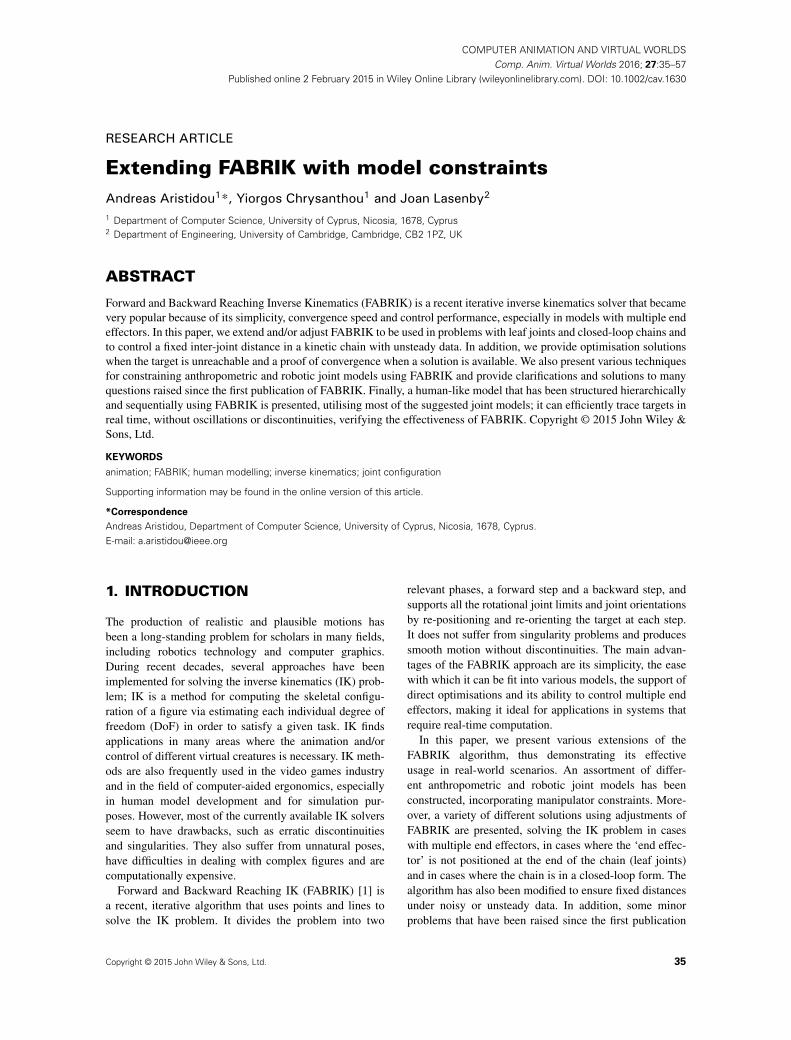
5.1. Anthropometric Joints
In this section, we present the six most common anthro-pometric joints and describe how to incorporate jointrestrictions using FABRIK. Figure 10 shows the six jointsdiscussed in this paper: the ball-and-socket, hinge, pivot,condyloid, saddle and gliding joints, indicating wherethey can be found on the human body. Note that reference[1] presented the main concept of how to apply jointrestrictions using FABRIK, giving as an example the ball-and-socket and hinge joints; in this paper, we demonstratehow joint restriction can be incorporated into the mostcommon anthropometric and robotic joint models. Somemore sophisticated anthropometric models (such as theshoulder model) can be formed by a combination ofthese techniques.
The ball-and-socket joint (or spheroidal joint) is a jointin which a ball moves within a socket so as to allow rotarymotion in every direction within certain limits. This is themost mobile type of joint in the human body, allowing thegreatest range of movements; it allows flexion, extension,rotation, abduction, adduction and circumduction. On theother hand, the hinge joint is the simplest type of joint;it can be found in the elbows, knees and the joints of thefingers and toes. It is a bone joint in which the articu-lar surfaces are moulded to each other in such a manneras to permit motion only in one plane/direction about asingle axis. It allows flexion and extension movements.The procedure for orientational and rotational control forboth the ball-and-socket and hinge joints is described indetail in [1].
A pivot joint is one in which a bone rotates aroundanother, permitting only rotating movement; the axis of aconvex articular surface is parallel with the longitudinalaxis of the bone. It can be found in the neck, allowinga side-to-side turn of the head. Given that the pivot jointallows only rotational movements, it is a requirement thatthe target should be moved to lie on the same line with thejoint, as illustrated in Figure 11. Thus, the target t is pro-jected on line l1 that passes through joints p1 and p2; thenew position of joint p3 is positioned on line l1 and hasdistance d2 from p2, while its final orientation is given bythe target and should be kept within the allowed limits. Theorientation can be adjusted by applying the orientationalprocedure of the FABRIK algorithm, as described in [1].
A condyloid joint (also called ellipsoidal joint) is anovoid articular surface that is received into an ellipticalcavity. This permits biaxial movements, that is, forward–backward and side to side, but not rotation. The condyloid
Comp. Anim. Virtual Worlds 2016; 27:35–57 © 2015 John Wiley & Sons, Ltd. 45DOI: 10.1002/cav

Extending FABRIK with model constraints A. Aristidou, Y. Chrysanthou and J. Lasenby
(b)(a)
(d)(c)
(f)(e)
Figure 9. The Forward and Backward Reaching Inverse Kinematics solution for inter-joint control in closed-loop problems. (a) Theinitial configuration of the problem. (b) The first phase of the algorithm, which is in a circular form, re-positions the joints of theclosed loop. (c) The second phase of the algorithm. (d) The third phase, where the other true joint positions contribute to correction
of inter-joint distances. (e and f) The last two phases that are identical to Phases 1 and 2, respectively.
joint allows flexion, extension, adduction, abduction andcircumduction. Examples of condyloid joints are the wristsand the radius carpal. Condyloid joints are dealt within a manner similar to the ball-and-socket joint, withoutapplying the orientational procedure because no rotationalmovement is allowed.
In a saddle joint (also known as a sellar joint), theopposing surfaces are reciprocally concave–convex. It canbe treated exactly in the same way as the condyloid joint,but different angle limits describe the allowable bounds.A saddle joint supports flexion, extension, adduction,abduction and circumduction; similarly, no axial rotation ispermitted. The thumb is an example of a saddle joint.
A gliding joint (also known as a plane joint) is a synovialjoint that, under physiological conditions, allows onlygliding or sliding (sideways) movements. The solution forthe gliding joint requires a relaxation of some of the con-ditions of the IK problem. The solution is demonstratedin Figure 12. The target is first projected onto the jointplane; if the projected position is within the joint limits,then re-position p3 on the line that passes through the targetand its projection with distance d2 from p2. In the case thatthe projected position is out of bounds, move the projectedtarget position accordingly to be within the allowable
limits and follow the same procedure. It is important tonote that no axis rotation is permitted.
5.2. Robotic Joints
A prismatic joint is a 1-DoF kinematic pair mainly usedin robotics and mechanisms. Prismatic joints provide asingle-axis sliding function with the axis of the joint coin-cident with the centre line of the sliding link. Because anyprismatic form can be used for the elements of a slidingpair, it does not have a specific axis (as a turning pair does),but merely an axial direction.
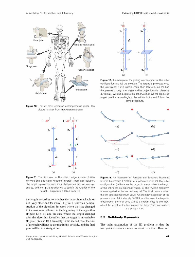
This family of joints changes the size of the linksconnecting the joints; thus, it is generally not supportedby most IK solvers. However, FABRIK can be adjusted todeal with prismatic joints, if details about the permissiblevariations of link sizes are available or the maximum andminimum sizes for each link are a priori known.
The solution described in this paper has minimum andmaximum values for di; this value can be adjusted on thefirst step or after the algorithm identifies that the target isunreachable, according to the user preferences or the modelspecifications. For instance, the user may choose to havethe mean of the length as the initialisation size and adjust
46 Comp. Anim. Virtual Worlds 2016; 27:35–57 © 2015 John Wiley & Sons, Ltd.DOI: 10.1002/cav
A. Aristidou, Y. Chrysanthou and J. Lasenby Extending FABRIK with model constraints
Figure 10. The six most common anthropometric joints. Thepicture is taken from http://anatomisty.com/
(b)(a)
Figure 11. The pivot joint. (a) The initial configuration and (b) theForward and Backward Reaching Inverse Kinematics solution.The target is projected onto line l1 that passes through joints p1
and p2, and joint p3 is re-oriented to satisfy the rotation of thetarget. This picture is taken from [1].
the length according to whether the target is reachable ornot (very close and far away). Figure 13 shows a demon-stration of the algorithm in cases where the size changedto the maximum allowed in the beginning of the algorithm(Figure 13(b–d)) and the case where the length changedafter the algorithm identifies that the target is unreachable(Figure 13(e and f)). Obviously, in the second case, the sizeof the chain will not be the maximum possible, and the finalpose will be in a straight line.
(b)(a)
Figure 12. An example of the gliding joint solution. (a) The initialconfiguration and (b) the solution. The target is projected ontothe joint plane; if it is within limits, then locate p3 on the linethat passes through the target and its projection with distanced2 from p2, with no axis rotation; otherwise, move the projectedtarget position accordingly to be within limits and follow the
same procedure.
(a) (b)
(c) (d)
(e) (f)
Figure 13. An illustration of Forward and Backward ReachingInverse Kinematics (FABRIK) for a prismatic joint. (a) The initialconfiguration. (b) Because the target is unreachable, the lengthof the link takes its maximum value. (c) The FABRIK algorithmis now applied in the normal way. (d) The final posture whenthe link takes its maximum value. An alternative approach of theprismatic joint: (e) first apply FABRIK, and because the target isunreachable, the final pose will be a straight line; (f) and then,adjust the length of the link to reach the target (the final posture
is a straight line).
5.3. Self-body Dynamics
The main assumption of the IK problem is that theinter-joint distances remain constant over time. However,
Comp. Anim. Virtual Worlds 2016; 27:35–57 © 2015 John Wiley & Sons, Ltd. 47DOI: 10.1002/cav

Extending FABRIK with model constraints A. Aristidou, Y. Chrysanthou and J. Lasenby
(a) (b) (c)
(d) (e) (f)
(g) (h) (i)
(j) (k) (l)
Figure 14. The deadlock case. (a) The initial configuration, where the bounds of joint p3 are indicated by red shading. (b) The forwardstep of the algorithm starts; thus, p4 is moved to the target position; (c) p3 is positioned on the line that passes through p4 and itsprevious position, (d) p2 is positioned by taking into consideration p3’s constraints and (e) p1 is placed on the line that passes throughp2 and its previous position. Then, in (f–i) is shown the backward step of the algorithm, where the root joint p1 returns to its initialposition and the rest of the joints are placed based on their joint constraints. If this procedure is repeated, the algorithm enters adeadlock situation, as shown in (j) during the forward and in (k) during the backward step. The algorithm will never find the exotic
solution, as shown in (l).
especially in human models, bones allow a small fluc-tuation in links’ length size that most researchers in theliterature use a mass–spring model to describe. Therefore,
there is a need to allow the IK solvers to increase anddecrease the inter-joint distance according to the user ormodel requirements. Huang and Pelachaud [38] proposed
48 Comp. Anim. Virtual Worlds 2016; 27:35–57 © 2015 John Wiley & Sons, Ltd.DOI: 10.1002/cav

A. Aristidou, Y. Chrysanthou and J. Lasenby Extending FABRIK with model constraints
a mass–spring-based variation of FABRIK to allow smallalterations on the link lengths; however, their energy trans-fer IK solver suffers from oscillations that derive fromusing the mass–spring system. In this section, we outline aself-body dynamic approach that uses FABRIK to replacethe mass–spring model, in cases where the bone length isallowed to change (such as extreme extensions of the armto reach a target).
The solution is similar to the prismatic joint case:the link length is slightly adjusted, based on the modelspecifications, in order to allow the end effector to reach thetarget. The approach utilised keeps the initial length ofthe links, and only when their target is unreachable doesit change the size; in that manner, the final posture is astraight line. Nevertheless, further investigation is neededto find out when the chain should be expanded or shrunk,according to the human anatomy and physiology, andhow much it can be expanded without the user perceivingit [56].
5.4. Dealing with the Deadlock Situation
The constrained version of the FABRIK algorithm encoun-ters a deadlock situation when the kinematic chain issmall in size and the joints close to the end effector havestrict constraints. The algorithm is then incapable of find-ing the exotic solution because the kinematic chain wasunable to bend enough and reach the target. This is dueto the structure of the algorithm in which each joint istreated independently; the algorithm does not take intoconsideration the restrictions in the previous (parent) ornext (child) joints in order to push, if possible, the kine-matic chain to bend further in the current joint.
Figure 14(a–k) illustrates the deadlock situation, andFigure 14(l) shows the desirable solution. Essentially,because of rotational constraints, the chain goes into adeadlock mode, when each iteration simply repeats theprevious position until the maximum number of triesis reached.
The solution to the problem is simple. First, check if thetarget is within the reachable area. It is important to notethat no optimisation is recommended when the target is outof reach and joint limitations exist, as there are joint con-straints that may be violated. If the target is not within thereaching area, the algorithm enters the termination process,and the iterative procedure is terminated. If the target iswithin reach but the kinematic chain cannot bend enoughto reach the target, check whether the distance between theend effector and the target becomes smaller after each iter-ation. If not, there is a chance that the algorithm has entereda deadlock situation, or the constraints do not allow thechain to bend more. Thus, during the backward step of thefirst iteration of the algorithm, bend the chain by 2ı (or15ı, 30ı, etc., based on the user requirements or the sys-tem specifications) in the opposite direction of the target,in order to allow other joints to bend more, and and thencontinue using the FABRIK algorithm in its normal state.If the end effector still does not reach the target, allow more
bending till the target is reached or a full turn of 360ı iscompleted. In that way, the algorithm pushes the parentjoints to their limits, allowing more flexion for the childjoints. Having a small rotation, for instance a rotation of2–5ı, is more effective compared with cases with largerdegrees of rotation, ensuring a smooth motion without dis-continuities and/or oscillations. This procedure does notaffect the efficiency of the FABRIK algorithm, especiallyin cases where the end effector is simply tracking the targetin time with high frequency rate.
5.5. Human-like Model
In this section, we describe an example of how the con-straints mentioned in Sections 4 and 5 can be applied toa human-like model. The purpose of setting up the modelis to show evidence of the flexibility of the algorithm andillustrate how it can easily be adapted to sequentially andhierarchically structured humanoid models. Obviously, thehuman-like model can be constrained further by taking intoconsideration physiological and anatomical constraints; fora well-designed human model, it is essential to study alljoint types and their constraint parameters.
5.5.1. The Human Geometry.
We have implemented a human model based on thegeometry described in Figure 15. In this example, thehuman model consists of nine ball-and-socket joints, fourhinge joints (knees and elbows), one pivot joint (neck)and five oriented end effectors that are defined by threemarkers. The implemented model comprises two orientedtargets to be tracked by the two hands, a serial chain withan oriented end effector that is tracked by the head and twomore oriented targets that are tracked by the feet.
Ball-and-Socket
Hinge
Pivot
End effector (markers)
Figure 15. Human configuration and the joint types used in ourexperimental model.
Comp. Anim. Virtual Worlds 2016; 27:35–57 © 2015 John Wiley & Sons, Ltd. 49DOI: 10.1002/cav

Extending FABRIK with model constraints A. Aristidou, Y. Chrysanthou and J. Lasenby
5.5.2. Hierarchical Structure.
The flexibility of the FABRIK algorithm enables imple-mentation of many different approaches to solve thisproblem. In this work, we show a simple solution, wherethe structure of the human skeleton is divided into smallerkinetic chains, which are then sequentially adapted intothe body posture in a hierarchical order. The adaptionhierarchy may vary between different models. Let usassume that, in this example, the two hands track the mov-ing targets, while the feet should remain constant at theirinitial position. Figure 16 shows the hierarchical structureof the humanoid model used in our experimental results.First in the hierarchy are the hand chains, which have theend effectors that track the targets. Figure 16(a) showsthe two hand chains, while Figure 16(b) the upper trian-gle of the main body. As the end effectors start to move
(b)(a)
(d)(c)
(f)(e)
Figure 16. Human structure: the different chains of the humanmodel in a hierarchical order; because hands are the end effec-tors controlling the movement of the character, they are firstin the hierarchy. (a) The upper kinematic chains (hands). (b)The upper triangle of the main body. Panels (a) and (b) areinter-connected; thus, the first iteration will sequentially move allthe joints. The left and right hands work simultaneously. (c) Thesub-base, (d) the lower triangle of the main body, (e) the lower
kinematic chains (feet) and (f) the chain of the head.
around, FABRIK re-locates the hand chains and the uppertriangle, to meet the inter-joint distance assumption. Thisprocess moves the sub-base (as presented in Figure 16(c))of the model to its new position. The algorithm is iter-ative, and it will be repeated till the distance betweenthe targets and the two end effectors is smaller than anindicated tolerance.
In the second stage of the algorithm, FABRIK isapplied to re-position the three remaining chains. First, itis applied to control the lower triangle of the main body, asshown in Figure 16(d), and then the leg chains, asshown in Figure 16(e). This is also an iterative pro-cess because, in this model, it is assumed that the feetpositions should remain constant. Finally, FABRIK isincorporated to re-position the head chain; this is not aniterative process because it is treated as a serial chain(Section 4.4.1).
Obviously, if the humanoid model is different, forinstance, there are four end effectors (the two hands andtwo feet), the upper and lower body will return twodifferent positions for the sub-base joint; the mid-point ofthese two positions will be chosen, as for the sub-basein the multiple-end-effector case, and the algorithm willcontinue iteratively till the distance between the targets andend effectors is less than an acceptable threshold.
The proposed human-like model has been adapted tothe Aristidou and Lasenby framework [30], which hasbeen integrated in the PhaseSpace Inc. mocap software.A similar implementation for hand modelling and recon-struction is presented in [28], where joint constraints havebeen incorporated using FABRIK on a hand. Similarly, dif-ferent models can be designed for various applications,ensuring that the targets will always remain within theallowable space.
6. EXPERIMENTAL RESULTS
In this section, we present the results of various imple-mentations and tests of the aforementioned optimisationsand joint and model structures for validation purposes. Theexperiments are demonstrated using a humanoid modelcontaining 14 partially constrained joints with five endeffectors. The IK problem for the humanoid model issolved sequentially using closed loops in a predefinedhierarchical order, as described in Section 5.5.
Forward and Backward Reaching IK, as shown in [1],performs faster than other IK solvers that has been tested;in this paper, we ensure that, when the target is unreachableand the optimisation step has been applied, the requisiteprocessing time has been reduced by a factor of 50–60times, depending on the termination condition and thepermitted error tolerance, while we add only 2% to the pro-cessing time in cases where the target is within reachingbounds. Furthermore, it is guaranteed that the kinematicchain will be straight, compared with when no optimisa-tion has been applied, where the straightness of the chainis based on the selected error tolerance.
50 Comp. Anim. Virtual Worlds 2016; 27:35–57 © 2015 John Wiley & Sons, Ltd.DOI: 10.1002/cav

A. Aristidou, Y. Chrysanthou and J. Lasenby Extending FABRIK with model constraints
The human-like model described in Section 5.5 isimplemented for testing purposes; even if only limitedinformation about the tracking pose is available, the pro-posed model returns visually natural solutions that satisfythe user or character constraints. Having available onlythe position and orientation of the end effector of themodel and the initial skeletal configuration, we were ableto successfully track the targets and reconstruct and ani-mate the avatar’s motion, while the model remains withina feasible set of postures. Figure 17 shows three differentexamples of target tracking where the end effectors (pointsof impact) move manually and the human model follows
smoothly, retaining the user-pre-defined constraints. In thefirst case, as shown in Figure 17(a), the hands (the onlytwo end effectors of the model) were able to follow thetargets without affecting the posture configuration of thecharacter. This happened because both targets are withinthe reaching limits and have similar distance from theirrespective end effectors. In contrast, Figure 17(b and c)shows the cases where the model posture changed becausetargets were not within the reachable bounds. The endeffector pulled the entire body in the direction of thetargets, so that it can eventually reach the targets. Nev-ertheless, in all cases, the algorithm returned a smooth
(a)
(b)
(c)
Figure 17. An example of Forward and Backward Reaching Inverse Kinematics implementation; the hands of the avatar smoothlytrack the moving targets, while the character posture remains within a feasible set defined by the joint and model constraints.
Comp. Anim. Virtual Worlds 2016; 27:35–57 © 2015 John Wiley & Sons, Ltd. 51DOI: 10.1002/cav

Extending FABRIK with model constraints A. Aristidou, Y. Chrysanthou and J. Lasenby
solution, ensuring that the joint and model limitations aresatisfied over time. The algorithm performs equally effec-tively in cases of four, five or even more targets and/orend effectors.
Figure 18 shows an example where the proposedhuman-like model was incorporated within a mocap frame-work. The human skeleton was reconstructed using theCameron and Lasenby method [58], which requires threemarkers available at each limb segment. In order to eval-uate our method, we have artificially deleted a number ofmarkers for an extended period so as to add noise in thejoint estimation. The large tracks of deleted marker datawere estimated, and the joint positions were calculatedusing [57], as shown in Figure 18(a). The joint positionswere further corrected using the proposed human model,as shown in Figure 18(b). It can be observed that theerror between the true and reconstructed (after deletions)skeletons has been reduced when FABRIK was applied, asFABRIK ensures that the inter-joint distance remains con-stant over time; this is more obvious when looking at thehip and shoulder joints of the skeletons in Figure 18. Thereconstructed postures, as also seen in the supplementaryvideo, are animated smoothly without discontinuities,
abnormalities or oscillations, resulting in an average jointerror of 1.02 cm, compared with 3.37 cm in cases whereFABRIK was not applied.
In order to push the FABRIK reconstruction ability toits limits, we implemented FABRIK so as to animate aconstrained human model by tracking five end effectorpositions (also named control points), the two hands, thetwo feet and the head. The mocap system returns thepositions of the control points and the root joint (seesub-base in Figure 16(c)), while the proposed humanoidmodel tracks the movement of the character; note thatthe human skeleton, meaning the inter-joint distances, isknown a priori. This is very useful to efficiently animateinteractive characters using low-cost mocap systems,especially in the computer game industry. Figure 19(a–c)shows different examples where the tracking characterkneels, kicks and punches, respectively. FABRIK ensuresthat the end effectors track the targets and the rest ofthe body satisfies its constraints, resulting in visuallynatural postures.
Figure 20 shows a snapshot of the FABRIK implemen-tation compared with the true joint positions, as returnedby the mocap system. It can be observed that the use
(a)
(b)
Figure 18. Snapshots of Forward and Backward Reaching Inverse Kinematics (FABRIK) implementation within a motion captureframework in cases where a number of marker were artificially deleted. (a) The joint positions were estimated using [57].(b) The joint positions were estimated using [57] and corrected by utilising FABRIK, which ensures that the inter-joint distanceremains constant over time. The true (before the deletions) skeleton in both cases is given in blue, while the reconstructed
in red.
52 Comp. Anim. Virtual Worlds 2016; 27:35–57 © 2015 John Wiley & Sons, Ltd.DOI: 10.1002/cav

A. Aristidou, Y. Chrysanthou and J. Lasenby Extending FABRIK with model constraints
of such a small number of control points may lead towrong joint estimates, as well as the production of arte-facts, especially in the shoulders and knees; however, thereconstructed skeleton respects the human model con-straints, even if some joints are not identical to the truejoint positions. The implemented model results in an aver-age positioning error of 1.66 cm; the joint with the higheraverage error was the left shoulder with 7.6 cm, while theknees and the elbows have an average error of 2.1 cm.The errors occurring in joint estimation, as well as theartefacts and oscillations, can be eliminated by addingmore control points, such as the hips and shoulders. Using
more control points will allow the kinematic chain toget into smaller closed loops, removing the noise pre-sented in the intermediate joints. In such a case, the arte-facts are significantly reduced, making the reconstructedjoint average error comparable with the case where thehuman skeleton is animated using the mocap system.The proposed method could be implemented in applica-tions where a fast interactive control is needed (e.g. inMicrosoft Kinect™) or in cases where it is desirable to ani-mate a human character using only a limited number ofcontrol points.
(a)
(b)
(c)
Figure 19. Snapshots of Forward and Backward Reaching Inverse Kinematics implementation when the human skeleton is controlledby five end effectors. The end effectors, which are animated using motion capture data, are in yellow, while the reconstructed joints
are in red.
Comp. Anim. Virtual Worlds 2016; 27:35–57 © 2015 John Wiley & Sons, Ltd. 53DOI: 10.1002/cav

Extending FABRIK with model constraints A. Aristidou, Y. Chrysanthou and J. Lasenby
(a)
(b)
Figure 20. Snapshots of the Forward and Backward Reaching Inverse Kinematics skeleton reconstruction compared with the truejoint positions, as returned by the motion capture system. The end effectors are in yellow, the true joint positions and the markersare in blue, while the reconstructed joints are in red. It can be seen that in (a) the skeleton has been successfully tracked andreconstructed, while in (b) there are wrong estimates, especially on the shoulders. Nevertheless, the reconstructed skeleton respects
the user and character constraints, even if some joints differ from their true value.
7. CONCLUSIONS
Forward and Backward Reaching IK is a simple, fast andreliable solver that uses an iterative method with points andlines to solve the IK problem. It divides the problem intotwo phases, a forward and backward reaching approach,and it is able to support a variety of different anthropo-metric and robotic joint types. Even though it is a recentalgorithm, it has become a popular IK solver becauseof its simplicity and flexibility, enabling easy adaptationinto different problems and models. In this paper, wepresent a framework that detects the cases where the targetis unreachable or not; in addition, we prove that FAB-RIK always converges to an answer if there is a solutionavailable. Furthermore, we introduce optimisation solu-tions when the targets are unreachable, in kinematic chainswith both single or multiple end effectors, converging to asolution in just a single iteration. FABRIK has been alsoadjusted to control a fixed inter-joint distance under noisyor flipped data, in serial or closed-loop chains. To the bestof our knowledge, FABRIK supports all the rotational andorientational joint limits by re-positioning and re-orientingthe target at each step. Consequently, we have incorporatedjoint constraints into different anthropometric and robotic
joints, showing that FABRIK is easily adaptable to differ-ent models and problems. A humanoid model is imple-mented, where FABRIK has been applied hierarchicallyand sequentially to track multiple targets and ensure fixedinter-joint distance. FABRIK remained executable inreal time, achieving good results in complex structuredhumanoid models with joint limitations and closed-loopforms. The efficiency of the proposed methodology wasfurther tested by tracking and animating a human skeletonthat uses only five control points, demonstrating its use inapplications where fast interactive control is needed.
Future work will see the introduction of the aforemen-tioned approaches in more complex models that take intoconsideration physiological and anatomical constraints.Further investigation is also needed to consider smallchanges in limb size, so as to add extra realism inhuman animation.
ACKNOWLEDGEMENTS
This project is co-financed by the Office of Naval ResearchGlobal (N62909-13-1-V090), the European RegionalDevelopment Fund and the Republic of Cyprus through theResearch Promotion Foundation (DIDAKTOR/0311/73).
54 Comp. Anim. Virtual Worlds 2016; 27:35–57 © 2015 John Wiley & Sons, Ltd.DOI: 10.1002/cav

A. Aristidou, Y. Chrysanthou and J. Lasenby Extending FABRIK with model constraints
The authors would also like to thank Dr Chrysis Georgiou(University of Cyprus), Mr Tracy McSheery and Dr KanAnant (PhaseSpace Inc.) for their valuable help.
REFERENCES
1. Aristidou A, Lasenby J. FABRIK: a fast, iterativesolver for the inverse kinematics problem. GraphicalModels 2011; 73(5): 243–260.
2. Korein JU. A Geometric Investigation of Reach. MITPress: Cambridge, MA, USA, 1985.
3. Paul RP, Shimano B, Mayer GE. Kinematic controlequations for simple manipulators. IEEE Transac-tions on System, Man and Cybernetics 1988; 11(6):1398–1406.
4. Tolani D, Goswami A, Badler NI. Real-time inversekinematics techniques for anthropomorphic limbs.Graphical Models 2000; 62(5): 353–388.
5. Fu Z, Yang W, Yang Z. Computer ‘experiments’on classical fluids. I. Thermodynamic properties ofLennard–Jones molecules. Journal of Mechanisms andRobotics 2013; 5: 1–7.
6. Balestrino A, De Maria G, Sciavicco L. Robust controlof robotic manipulators. In Proceedings of the 9th IFACWorld Congress, volume 5, 1984; 2435–440.
7. Wolovich WA, Elliott H. A computational techniquefor inverse kinematics. The 23rd IEEE Conference onDecision and Control 1984; 23: 1359–1363.
8. Baillieul J. Kinematic programming alternatives forredundant manipulators. In Proceedings of the IEEEInternational Conference on Robotics and Automation,volume 2, March 1985; 722–728.
9. Wampler CW. Manipulator inverse kinematic solutionsbased on vector formulations and damped least-squaresmethods. Proceeding of the IEEE Transactions onSystems, Man and Cybernetics 1986; 16(1): 93–101.
10. Nakamura Y, Hanafusa H. Inverse kinematic solu-tions with singularity robustness for robot manipulatorcontrol. Trans. ASME, Journal of Dynamic Systems,Measurement, and Control 1986; 108(3): 163–171.
11. Buss SR, Kim J-S. Selectively damped least squaresfor inverse kinematics. Journal of Graphics Tools2005; 10(3): 37–49.
12. Kenwright B. Inverse kinematics with dual-quaternions, exponential-maps, and joint limits. Inter-national Journal on Advances in Intelligent Systems2013; 6(1 and 2): 53–65.
13. Fletcher R. Practical Methods of Optimization, 2ndedn. Wiley-Interscience: New York, NY, USA, 1987.
14. Courty N, Arnaud E. Inverse kinematics using sequen-tial monte carlo methods. In Proceedings of the VConference on Articulated Motion and Deformable
Objects, volume 5098. LNCS, Mallorca, Spain, July9-11; 1–10.
15. Hecker C, Raabe B, Enslow RW, Deweese J,Maynard J, van Prooijen K. Real-time motion retarget-ing to highly varied user-created morphologies. ACMTransactions on Graphics (TOG) 2008; 27(3): 1–11.
16. Pechev AN. Inverse kinematics without matrixinvertion. In Proceedings of the IEEE InternationalConference on Robotics and Automation (ICRA ’08),Pasadena, CA, USA, May 19-23 2008; 2005–2012.
17. Grochow K, Martin SL, Hertzmann A, Popovic Z.Style-based inverse kinematics. In ACM Transactionson Graphics (TOG). ACM, New York, NY, USA,August 2004; 522–531.
18. Wu X, Tournier M, Reveret L. Natural character pos-ing from a large motion database. IEEE ComputerGraphics and Applications 2011; 31(3): 69–77.
19. Wei X, Chai J. Intuitive interactive human-characterposing with millions of example poses. IEEE Com-puter Graphics and Applications July 2011; 31(4):78–88.
20. Ho ESL, Shum HPH, Cheung YM, Yuen PC. Topol-ogy aware data-driven inverse kinematics. In ComputerGraphics Forum, October 2013.
21. Sumner RW, Zwicker M, Gotsman C, Popovic J.Mesh-based inverse kinematics. ACM Transactions onGraphics (TOG) 2005; 24(3): 488–495.
22. Der KG, Sumner RW, Popovic J. Inverse kinematicsfor reduced deformable models. In ACM SIGGRAPHPapers. ACM, New York, NY, USA, 2006; 1174–1179.
23. Wang L-CT, Chen CC. A combined optimizationmethod for solving the inverse kinematics problemsof mechanical manipulators. IEEE Transactions onRobotics and Automation 1991; 7(4): 489–499.
24. Kulpa R, Multon F. Fast inverse kinematics and kinet-ics solver for human-like figures. In International Con-ference on Humanoid Robots, IEEE-RAS, Tsukuba,Japan, December 2005; 38–43.
25. Müller-Cajar R, Mukundan R. Triangulation: a newalgorithm for inverse kinematics. In Proceedings of theImage and Vision Computing New Zealand 2007, NewZealand, December 2007; 181–186.
26. Mukundan R. A robust inverse kinematics algorithmfor animating a joint chain. International Journal ofComputer Applications in Technology 2009; 34(4):303–308.
27. Aristidou A, Lasenby J. Inverse kinematics: a review ofexisting techniques and introduction of a new fast iter-ative solver. Technical Reports F-INFENG/TR. 632,CUED, 2009.
28. Aristidou A, Lasenby J. Inverse kinematics solu-tions using conformal geometric algebra. In Guide to
Comp. Anim. Virtual Worlds 2016; 27:35–57 © 2015 John Wiley & Sons, Ltd. 55DOI: 10.1002/cav

Extending FABRIK with model constraints A. Aristidou, Y. Chrysanthou and J. Lasenby
Geometric Algebra in Practice, Dorst L, Lasenby J(eds). Springer: London, 2011; 47–62.
29. Alver J. A virtual hand for prosthetic training. Master’sThesis, Chalmers University of Technology, Gothen-burg, Sweden, 2011.
30. Aristidou A, Lasenby J. Real-time marker predictionand CoR estimation in optical motion capture. TheVisual Computer 2013; 29(1): 7–26.
31. Poddighe R, Roos N. A NAO robot paying tic-tac-toe:comparing alternative methods for inverse kinematics.In Proceedings of the 25th Belgium–Netherlands Arti-ficial Intelligence Conference, BNAIC’13, November2013.
32. Liu Y-C. Gesture and end-effector trajectory planningof robot manipulator using human motion imitation.Master’s Thesis, National Taipei University of Tech-nology, China, 2012.
33. Munshi SM. Analysis, investigation and design offlexible universal pneumatic industrial manipulatorsinvolving cartesian and joint control in the basis ofeconomic feasibility and appropriate technology. PhDthesis, University of New South Wales, Australia,2012.
34. Lo HS, Xie SSQ. Optimization of a redundant 4Rrobot for a shoulder exoskeleton. In Proceedings of theIEEE/ASME International Conference on AdvancedIntelligent Mechatronics (AIM), Wollongong,Australia, July 2013; 798–803.
35. Hwang S, Choi Y. Pose estimation of small-articulatedanimals using multiple view images. In Proceedings ofthe International Conference on Computer Graphics,Visualization and Computer Vision, WSCG ’15, June2014.
36. Ramachandran S, John NW. A fast inverse kinemat-ics solver using intersection of circles. In Proceedingsof the Eurographics UK Theory and Practice of Com-puter Graphics Conference. Eurographics, Bath, UK,September 2013.
37. Le Naour T, Courty N, Gibet S. Cinmatique guide parles distances. Revue lectronique Francophone dInfor-matique Graphique 2012; 6(1): 15–25.
38. Huang J, Pelachaud C. An efficient energy trans-fer inverse kinematics solution. In Motion in Games(MIG), volume 7660 of Lecture Notes in Computer Sci-ence, Kallmann M, Bekris KE (eds). Springer, 2012;278–289.
39. Moya S, Colloud F. A fast geometrically-driven pri-oritized inverse kinematics solver. In Proceedings ofthe XXIV Congress of the International Society ofBiomechanics (ISB 2013), August 2013; 1–3.
40. Bentrah A, Djeffal A, Babahenini M, Gillet C, Pudlo P,Taleb-Ahmed A. Full body adjustment using iterativeinverse kinematic and body parts correlation. In Com-
putational Science and Its Applications—ICCSA 2014,
volume 8584 of Lecture Notes in Computer Science.
Springer International Publishing, 2014; 681–694.
41. Blow J. Inverse kinematics with quaternion joint limits.Game Developer Magazine 2012: 16–18.
42. Wilhelms J, Gelder AV. Fast and easy reach-cone joint
limits. Journal of Graphic Tools 2001; 6(2): 27–41.43. Baerlocher P, Boulic B. Parametrization and range
of motion of the ball-and-socket joint. In Deformable
Avatars. Kluwer Academic Publishers, 2001; 180–190.44. Yamane K, Nakamura Y. Natural motion animation
through constraining and deconstraining at will. IEEE
Transactions on Visualization and Computer Graphics
2003; 9(3): 352–360.
45. Maurel W, Thalmann D. Human shoulder modeling
including scapulo-thoracic constraint and joint sinuscones. Computers & Graphics 2000; 24(2): 203–18.
46. Wang X, Verriest JP. A geometric algorithm to predict
the arm reach posture for computer-aided ergonomicevaluation. Journal of Visualization and Computer Ani-
mation 1998; 9(1): 33–47.
47. Klopcar N, Tomšic M, Lenarcic J. A kinematic modelof the shoulder complex to evaluate the arm-reachable
workspace. Journal of Biomechanics 2007; 40(1):
86–91.48. Herda L, Urtasun R, Hanson A, Fua P. Automatic
determination of shoulder joint limits using experimen-
tally determined quaternion field boundaries. Interna-
tional Journal of Robotics Research 2003; 22(6).
49. Badler NI, Phillips CB, Webber BL. Simulating
Humans: Computer Graphics Animation and Control.Oxford University Press: New York, Oxford, 1993.
50. White III AA, Panjabi MM. Clinical Biomechan-
ics of the Spine, 2nd edn. J.B. Lippincott Company:Michigan, USA, 1990.
51. Monheit G, Badler NI. A kinematic model of the
human spine and torso. IEEE Computer Graphics and
Applications 1991; 11(2): 29–38.
52. Rijpkema H, Girard M. Computer animation of
knowledge-based human grasping. In Proceedings of
the 18th Annual Conference on Computer Graphics
and Interactive Techniques. ACM, New York, NY,
USA, 1991; 339–348.53. Murray RM, Sastry SS, Zexiang L. A Mathemati-
cal Introduction to Robotic Manipulation. CRC Press,
Inc.: Boca Raton, FL, USA, 1994.54. Kaimakis P, Lasenby J. Gradient-based hand track-
ing using silhouette data. In Proceedings of the 3rd
International Symposium on Visual Computing (ISVC),
volume 1, Lake Tahoe, NV/CA, USA, November
26–28, 2007; 24–35.
56 Comp. Anim. Virtual Worlds 2016; 27:35–57 © 2015 John Wiley & Sons, Ltd.DOI: 10.1002/cav

A. Aristidou, Y. Chrysanthou and J. Lasenby Extending FABRIK with model constraints
55. Brown J, Latombe J-C, Montgomery K. Real-timeknot-tying simulation. The Visual Computer 2004;20(2): 165–179.
56. Harrison J, Rensink RA, van de Panne M. Obscuringlength changes during animated motion. ACM Trans-actions on Graphics 2004; 23(3): 569–573.
57. Aristidou A, Cameron J, Lasenby J. Predicting missingmarkers to drive real-time centre of rotation estima-tion. In Proceedings of the V Conference on ArticulatedMotion and Deformable Objects, volume 5098. LNCS,Mallorca, Spain, 2008; 238–247.
58. Cameron J, Lasenby J. A real-time sequential algo-rithm for human joint localization. In ACM SIG-GRAPH Posters. ACM Press, New York, USA, 2005;107.
SUPPORTING INFORMATIONSupporting information may be found in the online versionof this article.
AUTHORS’ BIOGRAPHIES
Andreas Aristidou is a post-docresearcher associated with the Depart-ment of Computer Science, Universityof Cyprus. He had been a CambridgeEuropean Trust fellow, at the Depart-ment of Engineering, University ofCambridge, where he obtained his PhD.Andreas has a BSc in Informatics and
Telecommunications from the National and KapodistrianUniversity of Athens (2005), and he is an honour graduate
of Kings College London (2006), where he obtained hisMSc degree in Mobile and Personal Communications. Hismain interests are focused on 3D human motion analysisand classification and human animation and involve opticalmotion capture, motion synthesis, real-time marker predic-tion and centre-of-rotation estimation, inverse kinematicsand applications of geometric algebra in engineering.
Yiorgos Chrysanthou is an Asso-ciate Professor at the Computer Sci-ence Department of the Universityof Cyprus, where he is heading theGraphics and Hypermedia Lab. He waseducated in the UK (BSc and PhDfrom Queen Mary and Westfield Col-lege) and worked for several years as a
research fellow and a lecturer at University College Lon-don. He has been a Visiting Researcher at the Universityof California at Berkeley, USA (1992), and at Tel-AvivUniversity, Israel (1997). His research interests are in thegeneral area of computer graphics and virtual/augmentedreality and applications.
Joan Lasenby received her BA andMMath in Mathematics from the Uni-versity of Cambridge (1983) and com-pleted her PhD in Radio Astronomy (atthe Mullard Radio Astronomy Obser-vatory, Cambridge) in 1987. She iscurrently a senior lecturer in the Sig-nal Processing and Communications
Group, Cambridge University Engineering Department.Her research interests include motion capture, computervision, geometric algebra and image processing.
Comp. Anim. Virtual Worlds 2016; 27:35–57 © 2015 John Wiley & Sons, Ltd. 57DOI: 10.1002/cav
Recommended


![1678 IAMBLICHUS ... de Mysteriis ... [Ed. Gale]](https://img.pdfslide.us/doc/110x75/55cf996a550346d0339d4a29/1678-iamblichus-de-mysteriis-ed-gale.jpg)