EXPLORING ELEMENTS THAT OBSTRUCT THESUCCESSFUL DEPLOYMENT OF PUMPKIN
BALLOONSFrank E. Baginski
�Dr. Willi W. Schur
Department of Mathematics P.O. Box 698The George Washington University Accomac, VA 23301
Washington, DC [email protected] [email protected]
Finite Element Modeling Continuous Improvement
FEMCI Workshop 2004
NASA Goddard Space Flight Center
Greenbelt, MD
May 6, 2004�Supported in part by NASA Award NAG5-5353
1
Consider two self-deploying structures
1. The zero-pressure natural shape balloon (ZPNS)(a) Flown by NASA since the 1970s(b) Free of deployment problems
2. The pumpkin balloon (still in development)(a) New design for NASA’s Ultra Long Duration Balloon (ULDB)(b) Deployment problems on a number of flights
Problem: Improper deployment - balloon may not achieve the designaltitude; film stress resultant levels could be many times greater than ex-pected by the design, and ultimately lead to a failure of the balloon enve-lope.
Approach: Use a finite element representation of the balloon and anoptimization-based solution process to explore conditions that must bepresent for proper deployment and those that favor flawed deployment.
Goal: Provide reliable design guidelines2
ZPNS and Pumpkin Balloon Designs
3
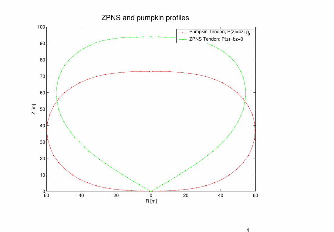
ZPNS and pumpkin profiles
−60 −40 −20 0 20 40 600
10
20
30
40
50
60
70
80
90
100
R [m]
Z [m
]Pumpkin Tendon; P(z)=bz+p
0ZPNS Tendon; P(z)=bz+0
4
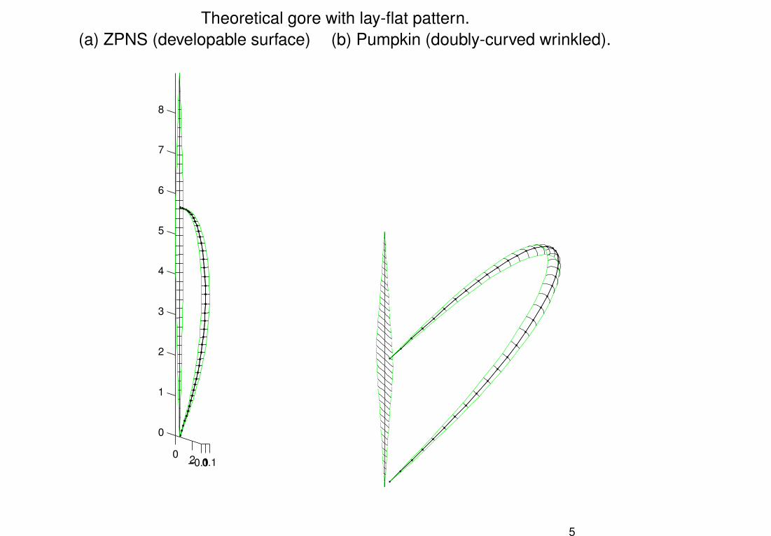
Theoretical gore with lay-flat pattern.(a) ZPNS (developable surface) (b) Pumpkin (doubly-curved wrinkled).
0 2−0.100.1
0
1
2
3
4
5
6
7
8
5
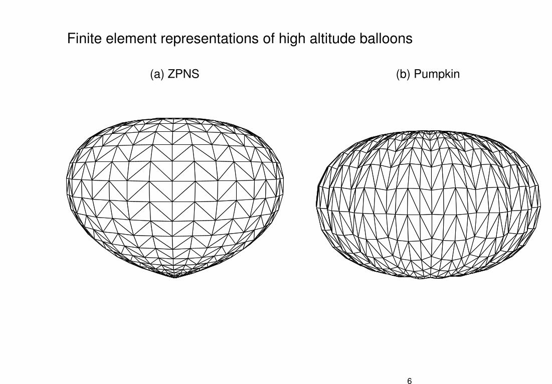
Finite element representations of high altitude balloons
(a) ZPNS (b) Pumpkin
6
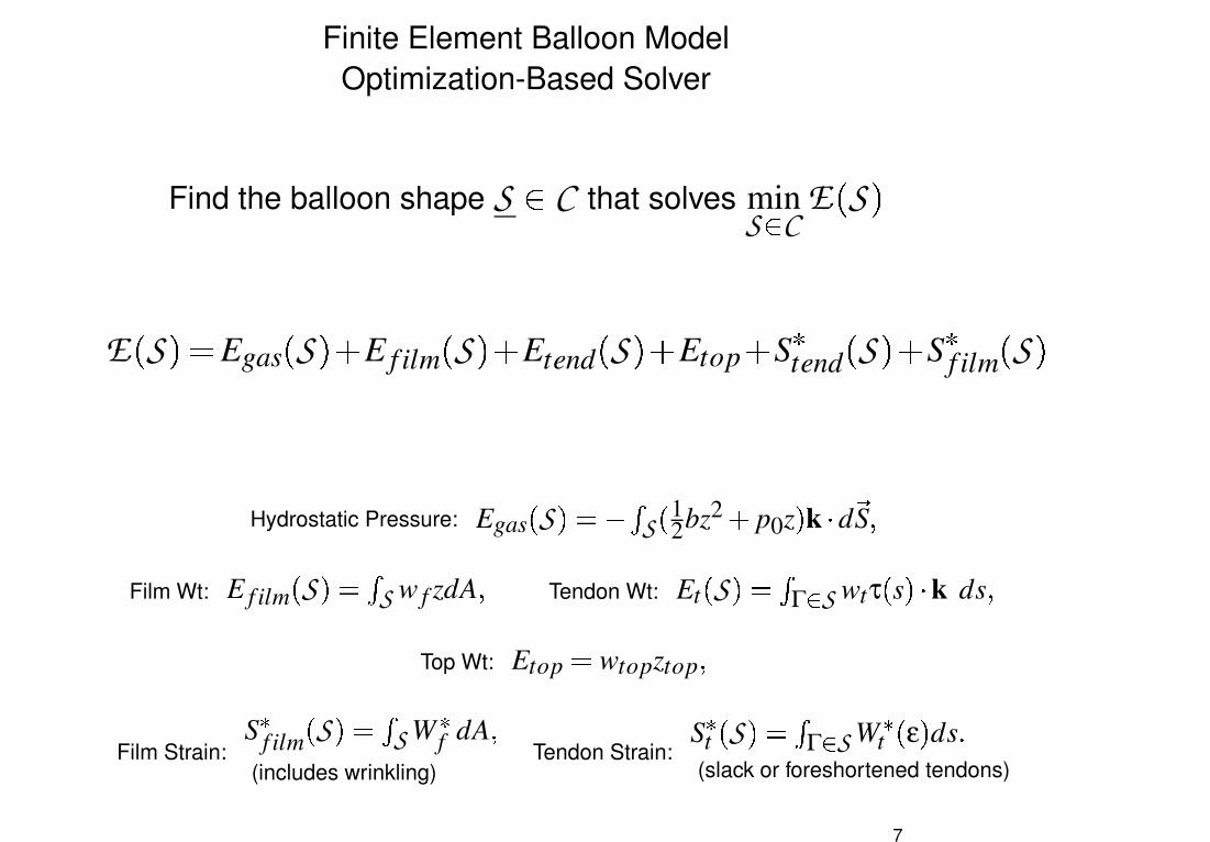
Finite Element Balloon ModelOptimization-Based Solver
Find the balloon shape S � C that solves minS � C
E�S �
E�S ��� Egas
�S ��� E f ilm
�S �� Etend
�S �� Etop � S tend
�S �� S f ilm
�S �
Hydrostatic Pressure: Egas � S �� � � S � 12bz2 � p0z � k � d �S �Film Wt: E f ilm � S �� � S w f zdA � Tendon Wt: Et � S �� � Γ � S wtτ � s ��� k ds �
Top Wt: Etop wtopztop �Film Strain:
S�f ilm � S �� � S W
�f dA �
(includes wrinkling)Tendon Strain:
S�t � S �� � à � S W
�t � ε � ds �
(slack or foreshortened tendons)
7
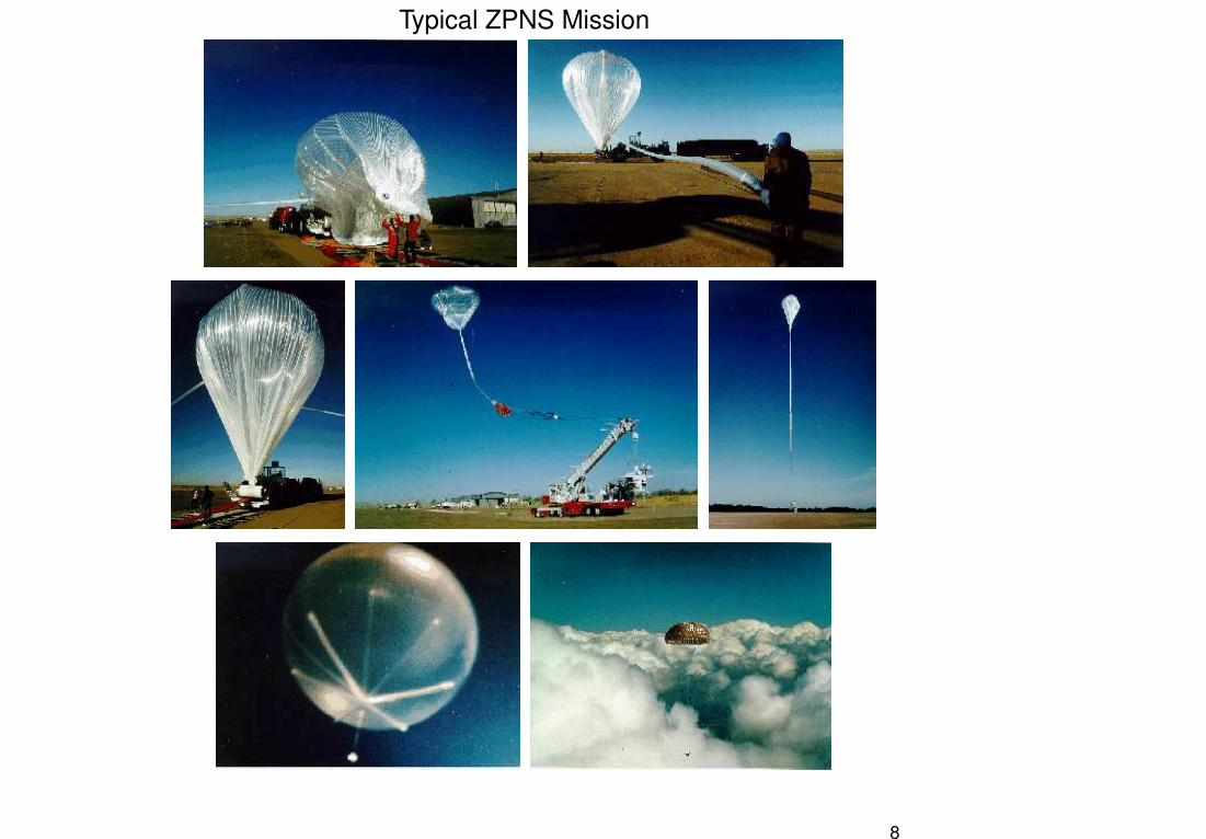
Typical ZPNS Mission
8
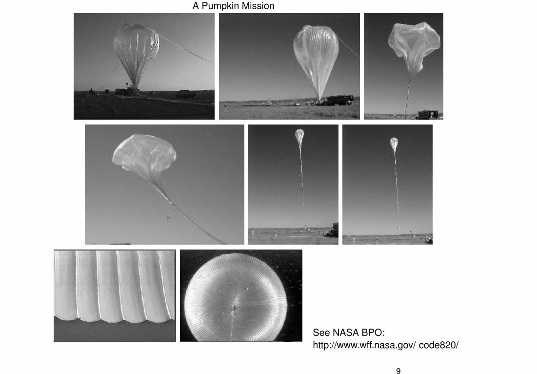
A Pumpkin Mission
See NASA BPO:http://www.wff.nasa.gov/ code820/
9
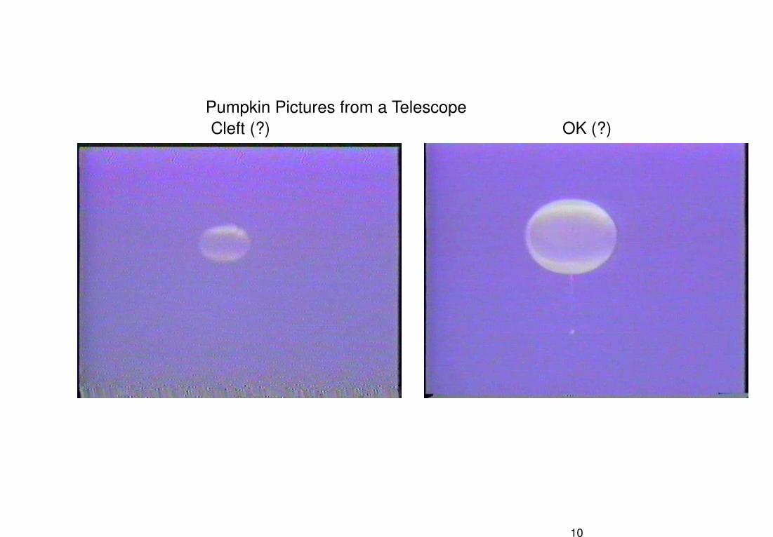
Pumpkin Pictures from a TelescopeCleft (?) OK (?)
10
Clefting in Flight 517
11
Features of Flight 517 Cleft
� Cleft was observed in the launch configuration� Cleft persisted through ascent phase� Cleft was maintained once float altitude was achieved and balloon was
fully pressurized
12
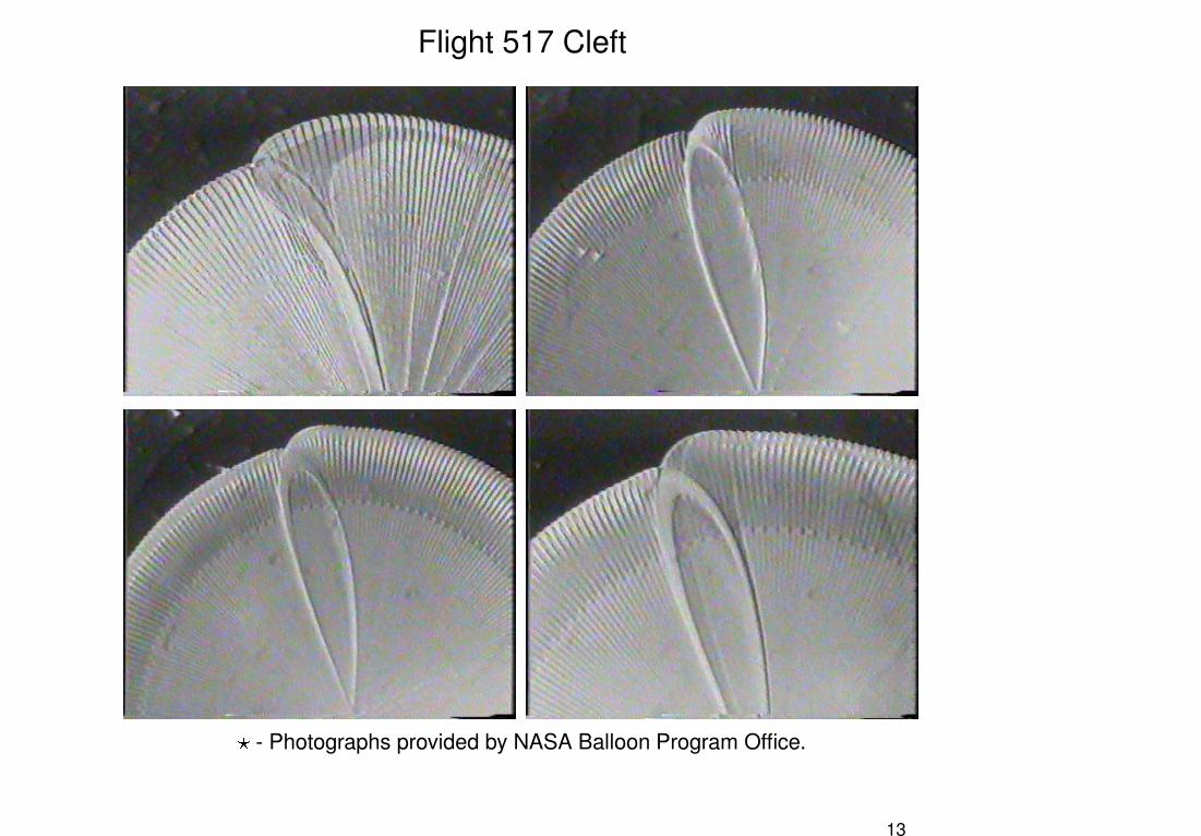
Flight 517 Cleft
� - Photographs provided by NASA Balloon Program Office.
13
Questions
� Is clefting an inherent problem with large pumpkin balloons?� Is clefting due to a mechanical locking that prevents proper deploy-
ment?� Given a balloon design, can we predict if an undesirable equilibrium is
likely to occur?
Observations
Experiments with small balloons and experience with test flights involving
large balloons suggest increasing the number of gores increases the
chance of improper deployment
14
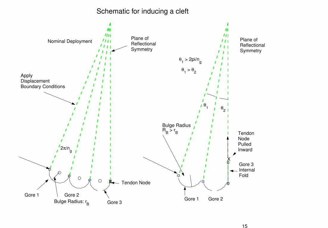
Schematic for inducing a cleft
Gore 1 Gore 2 Gore 3
Bulge RadiusR
B > r
B
Gore 1 Gore 2
Gore 3InternalFold
Nominal Deployment
Apply Displacement Boundary Conditions
Bulge Radius: rB
Tendon Node
X
Tendon Node Pulled Inward
X
2π/ng
θ1 > 2pi/n
g
θ1 θ
2
θ1 > θ
2
Plane of Reflectional Symmetry
Plane ofReflectionalSymmetry
15
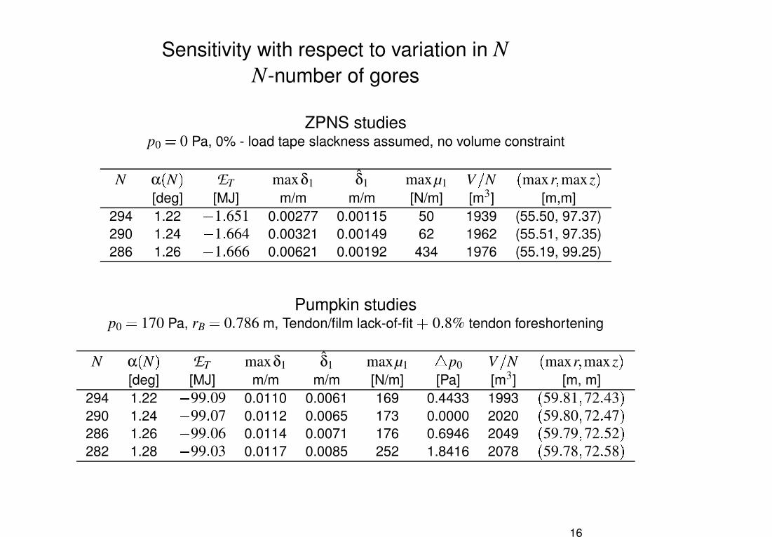
Sensitivity with respect to variation in NN-number of gores
ZPNS studiesp0 � 0 Pa, 0% - load tape slackness assumed, no volume constraint
N α � N � ET maxδ1 δ̂1 maxµ1 V � N � maxr� maxz �[deg] [MJ] m/m m/m [N/m] [m3] [m,m]
294 1.22 1 ! 651 0.00277 0.00115 50 1939 (55.50, 97.37)290 1.24 1 ! 664 0.00321 0.00149 62 1962 (55.51, 97.35)286 1.26 1 ! 666 0.00621 0.00192 434 1976 (55.19, 99.25)
Pumpkin studiesp0 � 170 Pa, rB � 0 ! 786 m, Tendon/film lack-of-fit " 0 ! 8% tendon foreshortening
N α � N � ET maxδ1 δ̂1 maxµ1 # p0 V � N � maxr� maxz �[deg] [MJ] m/m m/m [N/m] [Pa] [m3] [m, m]
294 1.22 99 ! 09 0.0110 0.0061 169 0.4433 1993 � 59 ! 81 � 72 ! 43 �290 1.24 99 ! 07 0.0112 0.0065 173 0.0000 2020 � 59 ! 80 � 72 ! 47 �286 1.26 99 ! 06 0.0114 0.0071 176 0.6946 2049 � 59 ! 79 � 72 ! 52 �282 1.28 99 ! 03 0.0117 0.0085 252 1.8416 2078 � 59 ! 78 � 72 ! 58 �
16
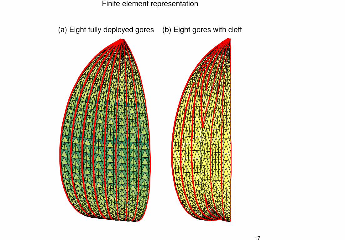
Finite element representation
(a) Eight fully deployed gores (b) Eight gores with cleft
17
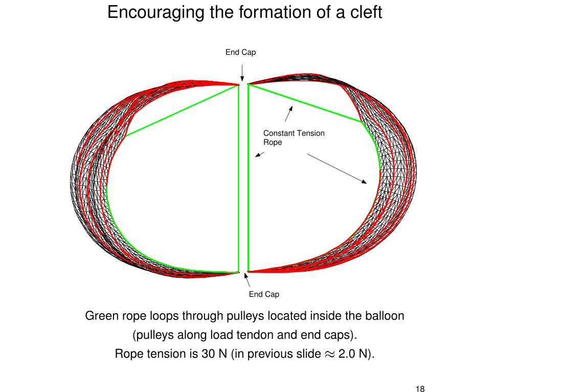
Encouraging the formation of a cleft
End Cap
End Cap
Constant TensionRope
Green rope loops through pulleys located inside the balloon
(pulleys along load tendon and end caps).
Rope tension is 30 N (in previous slide $ 2.0 N).
18
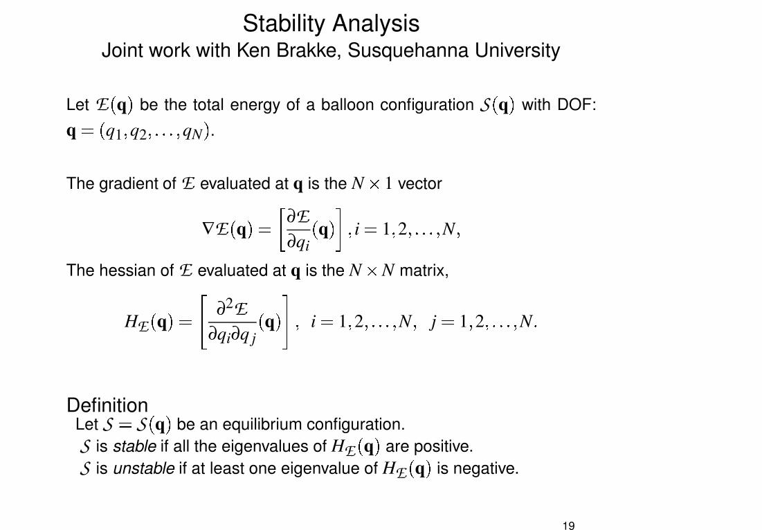
Stability AnalysisJoint work with Ken Brakke, Susquehanna University
Let E � q � be the total energy of a balloon configuration S � q � with DOF:
q � q1 � q2 �%�&�&�'� qN � .The gradient of E evaluated at q is the N ( 1 vector
∇E � q �) * ∂E∂qi
� q �,+-� i 1 � 2 �&�&�&�%� N �The hessian of E evaluated at q is the N ( N matrix,
HE � q �� . ∂2E∂qi∂q j
� q �0/ � i 1 � 2 �&�&�&�%� N � j 1 � 2 �&�%�&�&� N �Definition
Let S S � q � be an equilibrium configuration.S is stable if all the eigenvalues of HE � q � are positive.S is unstable if at least one eigenvalue of HE � q � is negative.
19
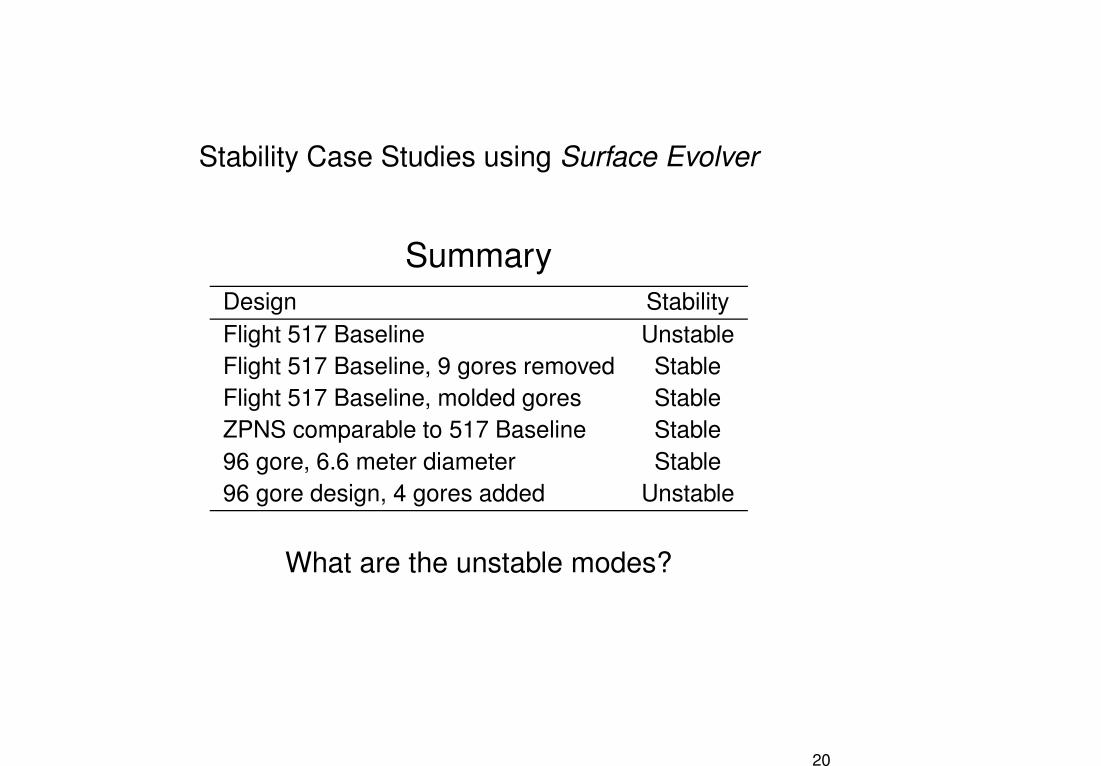
Stability Case Studies using Surface Evolver
SummaryDesign StabilityFlight 517 Baseline UnstableFlight 517 Baseline, 9 gores removed StableFlight 517 Baseline, molded gores StableZPNS comparable to 517 Baseline Stable96 gore, 6.6 meter diameter Stable96 gore design, 4 gores added Unstable
What are the unstable modes?
20
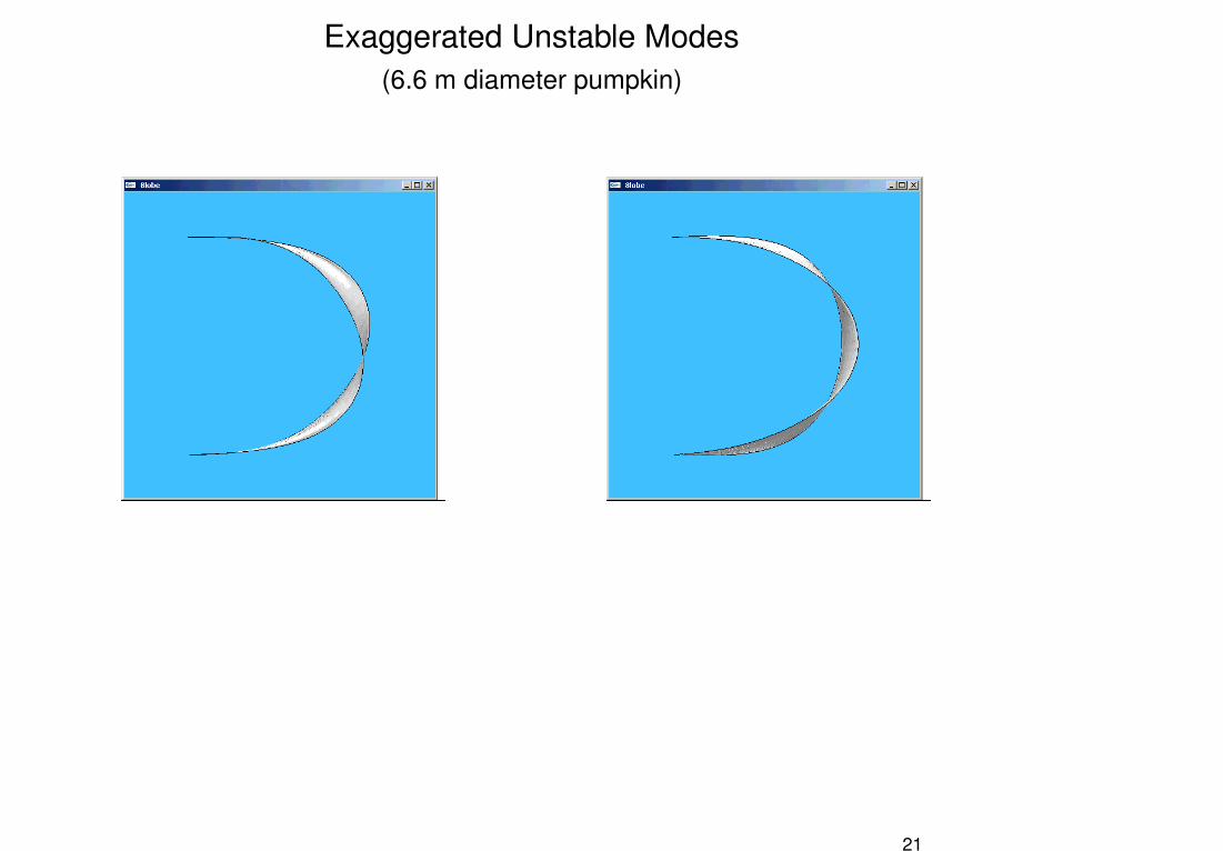
Exaggerated Unstable Modes(6.6 m diameter pumpkin)
21
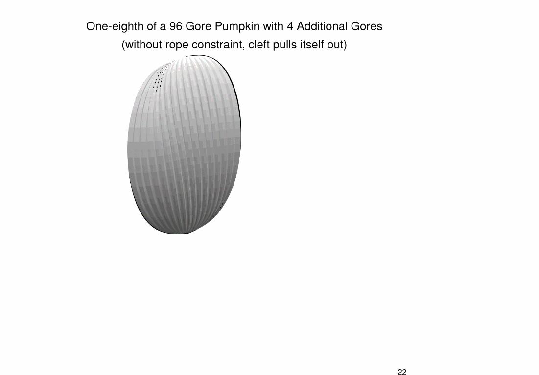
One-eighth of a 96 Gore Pumpkin with 4 Additional Gores
(without rope constraint, cleft pulls itself out)
22
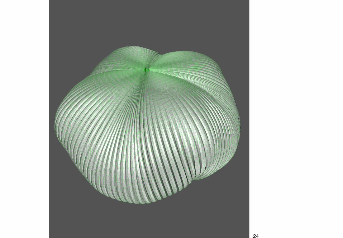
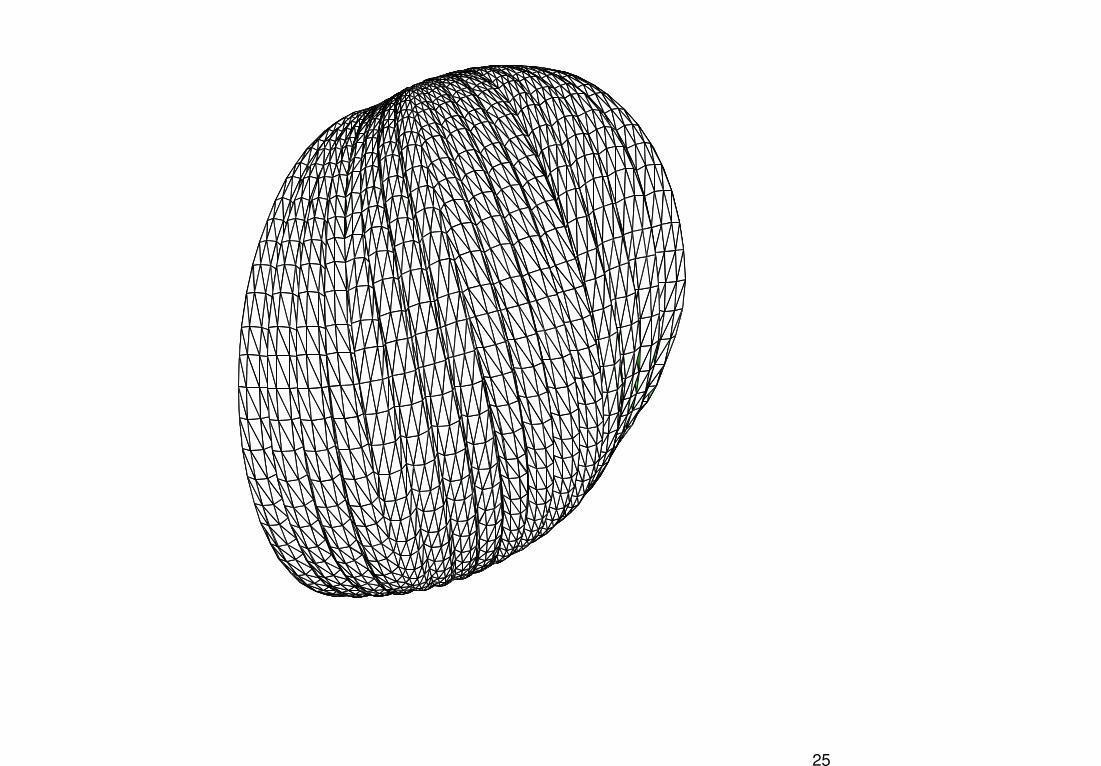
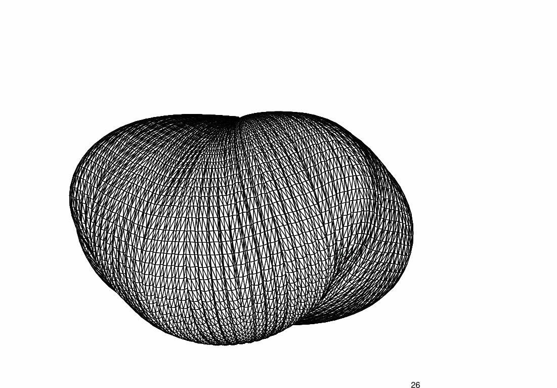
An Unstable Equilibrium Configuration
Nominal 96 Gore Pumpkin with 32 Additional Gores
23
24
25
26
Summary
� Preliminary analysis suggests that our FE-balloon representation can
model off-nominal shapes, including cleft-modes and other undesir-
able equilibria� Variational formulation and optimization-based solution process works
well
27
Future Work
Short Term� Demonstrate analytical capabilityto predict/avoid clefting 1 2 Corroborate with test results on
moderately sized pumpkin balloons� Investigate the possibility for mechanical locking� Continue stability analysis
Long Term� Provide reliable design guidelines
28
Recommended


![[MS-WDSOSD]: Windows Deployment Services · PDF fileWindows Deployment Services Operation System ... Services Operation System Deployment Protocol . Windows Deployment Services Operation](https://img.pdfslide.us/doc/110x75/5ab28f017f8b9abc2f8dbd37/ms-wdsosd-windows-deployment-services-deployment-services-operation-system.jpg)