124
��������� � ��
����� ������������������� �������� ���� ���� ����� ��������
� ����� !�"� #$%&�' ��'������'(�%)%*$ ��"�'%+,��-�"#.��#%&��'(�� '����/ 0"%�'%��# '�12�. � ��3�*(4���4-)
������ ��/%)456�%475889
��������� � �� �
����� ������������������� �������� ���� ���� ����� ��������
�������
��� � ��� ���������� ��������� ��� ����������� ���� ���������������������������������������� ��!� ���� ����! �����"� ��� ����!� ������ ��#��� �� !� ������ ��� ��� ������ ����� ���� ���������� ���� ���$������� ����#� %&&�'("�� ������#��� ����� �������)��� ���������� ���� ������!� ������� ��� ���"� ��� �� �������� ��� ������� ��� ���� ��*���� ��� ��� ��!��� ��� �������� ����� �������� �����!������ ��� #����� #��� ���������"� ����� ������� #��� ��� ������� ����� ����+�� �������� ����� ����� ��� ��� ����������� ��� ������� ��� ���"� ��� ������ ��� ������������� �������������������������������#���� ����!� �� ������!������������� ��������� �������� �!��������� ������!������ ���$����������������������� �����"
�������,����� ������-� ������������� ���-� ����!� �����-� ����������� ����
.�/�0���/123��/45�607�38��0124���9����450�4'�198�/5�0� 8��13�4'��1�13�0�4'�37�30:��5�4'
3� ����� �(�����#���� ������� �!;���#�!�� #� <;�(���)�� ��;������ �=#>)�� ����)���� �);��(��#��� �� ����������� ���(� �� �� ���� �"� 1);��(��� #�)�(�;�� ��?@� #����AB� #� <;�(���)�� ��;������ �=#>)�� ���� (�)�����(>�����#�A�� ��?�C� %&&� '("� ��C>��� �<#��?� ������� ���� �������� ����)�C� ���� #���)�����!�"� 1��(�����(���?��AB� (��)�� ����#���)�����!�� ��� )@��� ��������� A���� ��� �<#����!;�A�"� .������ �<#��?�# ;�#� �;����*A�� �)�����(��C� ����(�(���� ��� ������)��C>� ��!�� (C�#�)�"� 3�)�(���� �(������AB� �!<���� �����#����� ;��� �� ��C�)��#���������C<#��)�����(�����#���C@������C�(>A��C� � ���)����#�����)�����(��� ����(�(�D"
���� ��������,� ����#���)�����-� �(��� �!;���-��);��(��� ;���#�-��=#>)��;����AB
������������
Excessive reverberation in the range of low frequencies andthe occurrence of echo, in particular, multiple echo, are themost difficult and, unfortunately, common acoustic defects.Echo is a phenomenon resulting from the time differencebetween the direct and reflected sounds. The human hear-ing system can identify delays greater than 50 ms forspeech, and greater than 80 ms for music if the signal levelabove the acoustic background is appropriate. If the delaybetween the direct and reflected waves is smaller than 50ms, it produces the impression of an extended sound. Thisstudy has demonstrated usefulness of commonly availablepanels, such as drywalls reinforced with fibre or sand-wiched between sheets of paper, in the construction of ef-fective acoustic systems.
� ��������������������������������
��������������������������
�������������
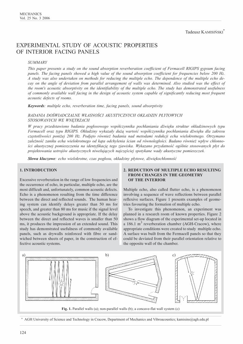
Multiple echo, also called flutter echo, is a phenomenoninvolving a sequence of wave reflections between parallelreflexive surfaces. Figure 1 presents examples of geome-tries favouring the formation of multiple echo.
To investigate this phenomenon, an experiment wasplanned in a research room of known properties. Figure 2shows a flow diagram of the experimental set-up located ina 186.1 m3 reverberation chamber (AGH-Cracow), whereappropriate conditions were created to study multiple echo.A surface was built from the Fermacell panels so that theycould be deviated from their parallel orientation relative tothe opposite wall of the chamber.
���������"�))�)+�))�:�;1�%�<-�"�))�)+�))�:0;1�'%�'�!�<&)�#+�))�$�#�.:';
�; 0; ';
125
������ ��/%)456�%475889
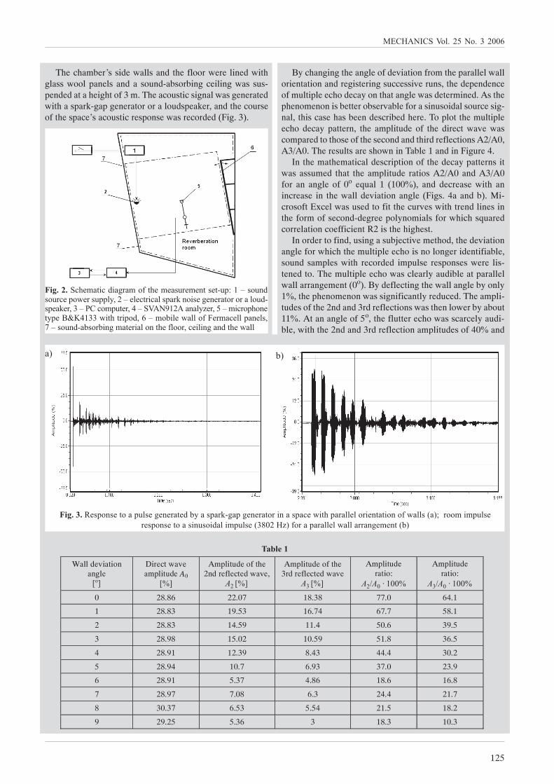
The chamber’s side walls and the floor were lined withglass wool panels and a sound-absorbing ceiling was sus-pended at a height of 3 m. The acoustic signal was generatedwith a spark-gap generator or a loudspeaker, and the courseof the space’s acoustic response was recorded (Fig. 3).
By changing the angle of deviation from the parallel wallorientation and registering successive runs, the dependenceof multiple echo decay on that angle was determined. As thephenomenon is better observable for a sinusoidal source sig-nal, this case has been described here. To plot the multipleecho decay pattern, the amplitude of the direct wave wascompared to those of the second and third reflections A2/A0,A3/A0. The results are shown in Table 1 and in Figure 4.
In the mathematical description of the decay patterns itwas assumed that the amplitude ratios A2/A0 and A3/A0for an angle of 0o equal 1 (100=), and decrease with anincrease in the wall deviation angle (Figs. 4a and b). Mi-crosoft Excel was used to fit the curves with trend lines inthe form of second-degree polynomials for which squaredcorrelation coefficient R2 is the highest.
In order to find, using a subjective method, the deviationangle for which the multiple echo is no longer identifiable,sound samples with recorded impulse responses were lis-tened to. The multiple echo was clearly audible at parallelwall arrangement (0o). By deflecting the wall angle by only1=, the phenomenon was significantly reduced. The ampli-tudes of the 2nd and 3rd reflections was then lower by about11=. At an angle of 5o, the flutter echo was scarcely audi-ble, with the 2nd and 3rd reflection amplitudes of 40= and
���������'(�.�# '� �*"�.%&#(�.����"�.��#��#<�->?@�%����%�"'�-%+�"��--)$,5@�)�'#" '�)�-�"2�% ��*���"�#%"%"�)%��<�-��2�",7@��'%.-�#�",A@�/��B?5����)$��",6@. '"%-(%��#$-�CDA?77+ #(#" -%�,9@.%0 )�+�))%&��".�'�))-���)�,E@�%���<�0�%"0 �*.�#�" �)%�#(�&)%%",'� ) �*���#(�+�))
�; 0;
�����������-%���#%�-�)��*���"�#��0$��-�"2<*�-*���"�#%" ���-�'�+ #(-�"�))�)%" ��#�# %�%&+�))�:�;1"%%. .-�)��"��-%���#%�� ���% ��) .-�)��:7F85��;&%"�-�"�))�)+�))�""��*�.��#:0;
�������
Wall deviation angle
Direct wave amplitude A0
[%]
Amplitude of the 2nd reflected wave,
A2 [%]
Amplitude of the 3rd reflected wave
A3 [%]
Amplitude ratio:
A2/A0 ⋅ 100%
Amplitude ratio:
A3/A0 ⋅ 100%
0 28.86 22.07 18.38 77.0 64.1
1 28.83 19.53 16.74 67.7 58.1
2 28.83 14.59 11.4 50.6 39.5
3 28.98 15.02 10.59 51.8 36.5
4 28.91 12.39 8.43 44.4 30.2
5 28.94 10.7 6.93 37.0 23.9
6 28.91 5.37 4.86 18.6 16.8
7 28.97 7.08 6.3 24.4 21.7
8 30.37 6.53 5.54 21.5 18.2
9 29.25 5.36 3 18.3 10.3
G=H ����� ����� ��I��J���� ��I��J������
126
�� ���������������������������� !�" ���"�� ������ ! ����� �!�"��#������
����������-�����'�%&��I��$%& �$'( )� *+�%+$),-%& .�,�(( (�,,�$' - $%)/�((�0 K�-+$ �/+%&��+$��+��(/�* ��,1 2�34� . $� $1 )��I��$%& �$'( )� *+�%+$),-%& .�,�(( (�,,�$' - $%)/�((�0 K�-+$ �
/+%&��+$��+��(/�* ��,1 253
44�, respectively. Further reduction in the flutter echo oc-curred with increasing the angle. After repeated hearings, itwas found that for wall deviation angles above 6o, the phenom-enon of multiple echo is not identifiable. This provides animportant guideline for designers of all spaces intended forpeople, especially spaces with special acoustic requirements.
� ������������������ �����!���
������������������������
���������������������������
The effect of the room’s acoustic absortion on the ability toidentify multiple echo was studied in the measurement standdescribed above. The experiment consisted in recording theroom’s impulse responses for varying amounts of sound ab-sorbing material in the chamber. The source signal was pro-
duced by a spark-gap generator. For each variant of fillingthe chamber with sound absorbing material, with walls ar-ranged in parallel (0o), the reverberation time was measuredin accordance with the PN-EN ISO 3382:2001 standard.
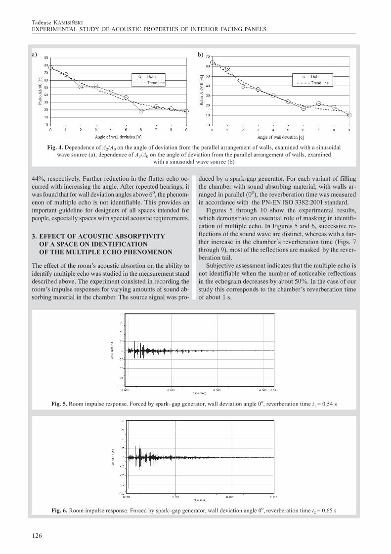
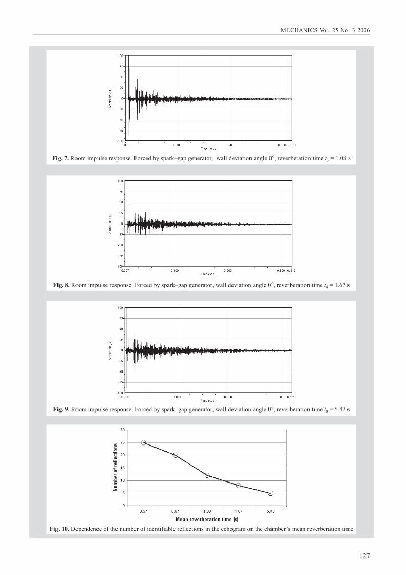
Figures 5 through 10 show the experimental results,which demonstrate an essential role of masking in identifi-cation of multiple echo. In Figures 5 and 6, successive re-flections of the sound wave are distinct, whereas with a fur-ther increase in the chamber’s reverberation time (Figs. 7through 9), most of the reflections are masked by the rever-beration tail.
Subjective assessment indicates that the multiple echo isnot identifiable when the number of noticeable reflectionsin the echogram decreases by about 50�. In the case of ourstudy this corresponds to the chamber’s reverberation timeof about 1 s.
�����"���%%. .-�)��"��-%���4�%"'��0$�-�"2@*�-*���"�#%",+�))��! �# %���*)�8%,"�!�"0�"�# %�# .���L�����
�����#���%%. .-�)��"��-%���4�%"'��0$�-�"2@*�-*���"�#%",+�))��! �# %���*)�8%,"�!�"0�"�# %�# .��L����
�� �
127
��������������������
�����$���%%. .-�)��"��-%���4�%"'��0$�-�"2@*�-*���"�#%",+�))��! �# %���*)�8%,"�!�"0�"�# %�# .���L�����
�����%���%%. .-�)��"��-%���4�%"'��0$�-�"2@*�-*���"�#%",+�))��! �# %���*)�8%,"�!�"0�"�# %�# .���L����
�����&���%%. .-�)��"��-%���4�%"'��0$�-�"2@*�-*���"�#%",+�))��! �# %���*)�8%,"�!�"0�"�# %�# .���L�����
������'����-�����'�%&#(���.0�"%& ���# & �0)�"�&)�'# %�� �#(��'(%*"�.%�#(�'(�.0�"M�.���"�!�"0�"�# %�# .�
128
��������� � ��
����� ������������������� �������� ���� ���� ����� ��������
��������������"�.��#�#���+ #(#(��#�� ���'%��# '�$�#�.:�;1�'%��# '�$�#�.��" �* ��#�))�# %�:0;
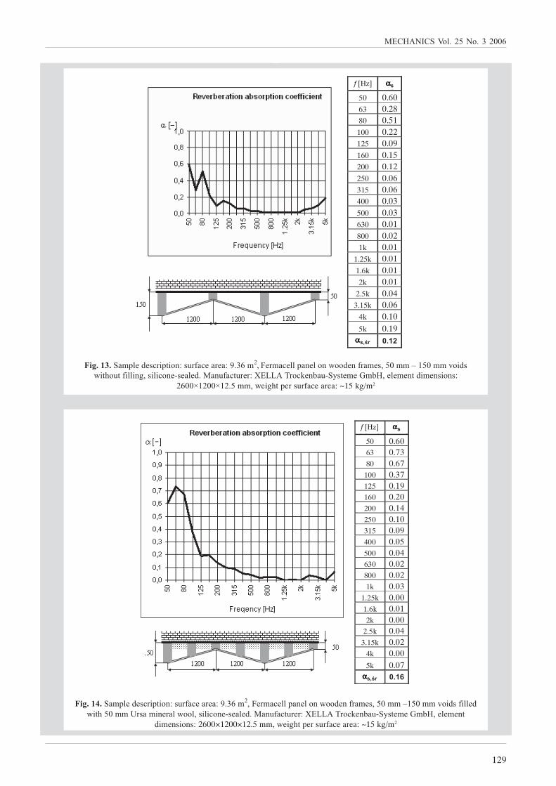
����������.-)����'" -# %���"&�'��"��>B479.5,��".�'�))-���)%�+%%���&"�.��,?88..!% ��+ #(%�#& )) �*,� ) '%��<���)��,����&�'#�"�">������"%'2��0��<�$�#�.��.0�,�)�.��#� .��� %��>5988N?588N?546..,
+� *(#-�"��"&�'��"��>O?62*�.5
�������� ����������������������
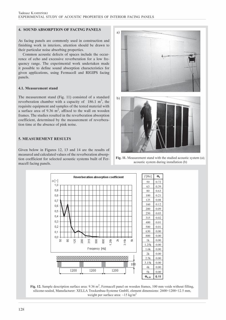
As facing panels are commonly used in construction andfinishing work in interiors, attention should be drawn totheir particular noise absorbing properties.
Common acoustic defects of spaces include the occur-rence of echo and excessive reverberation for a low fre-quency range. The experimental work undertaken madeit possible to define sound absorption characteristics forgiven applications, using Fermacell and RIGIPS facingpanels.
�������()*�+�,-�(-�,.
The measurement stand (Fig. 11) consisted of a standardreverberation chamber with a capacity of 186.1 m3, therequisite equipment and samples of the tested material witha surface area of 9.36 m2, affixed to the wall on woodenframes. The studies resulted in the reverberation absorptioncoefficient, determined by the measurement of reverbera-tion time at the absence of pink noise.
���������������������
Given below in Figures 12, 13 and 14 are the results ofmeasured and calculated values of the reverberation absorp-tion coefficient for selected acoustic systems built of Fer-macell facing panels.
��
��
f [Hz] αs 50 0.72
63 0.39
80 0.63
100 0.21
125 0.08
160 0.12
200 0.09
250 0.03
315 0.02
400 0.01
500 0.01
630 0.00
800 0.00
1k 0.00
1.25k 0.00
1.6k 0.00
2k 0.00
2.5k 0.00
3.15k 0.00
4k 0.00
5k 0.00
��� 0.11
f [Hz] ααααα�
����ααααα����
129
������ ��/%)456�%475889
�����������.-)����'" -# %�>��"&�'��"��>B479.5,��".�'�))-���)%�+%%���&"�.��,68..@?68..!% ��& ))��+ #(68..�"��. ��"�)+%%),� ) '%��<���)��4����&�'#�"�">������"%'2��0��<�$�#�.��.0�,�)�.��#
� .��� %��>2600×1200×12.5 mm, weight per surface area: ~15 kg/m2
f [Hz] αs 50 0.60 63 0.73 80 0.67
100 0.37 125 0.19 160 0.20 200 0.14 250 0.10 315 0.09 400 0.05 500 0.04 630 0.02 800 0.02 1k 0.03
1.25k 0.00 1.6k 0.01 2k 0.00
2.5k 0.04 3.15k 0.02
4k 0.00
5k 0.07
��� 0.16
f [Hz] ααααα�
���ααααα����
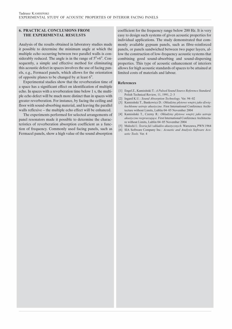
����������.-)����'" -# %�>��"&�'��"��>B479.5,��".�'�))-���)%�+%%���&"�.��,68..@?68..!% ��+ #(%�#& )) �*,� ) '%��<���)��4����&�'#�"�">������"%'2��0��<�$�#�.��.0�,�)�.��#� .��� %��>
5988N?588N?546..,�+eight per surface area: ~15 kg/m2
f [Hz] αs 50 0.60 63 0.28 80 0.51 100 0.22 125 0.09 160 0.15 200 0.12 250 0.06 315 0.06 400 0.03 500 0.03 630 0.01 800 0.02 1k 0.01
1.25k 0.01 1.6k 0.01 2k 0.01
2.5k 0.04 3.15k 0.06
4k 0.10 5k 0.19
��� 0.12
f [Hz] ααααα�
���ααααα����
130
��������� � ��
����� ������������������� �������� ���� ���� ����� ��������
�� �����������������������
�����/�������������������
Analysis of the results obtained in laboratory studies madeit possible to determine the minimum angle at which themultiple echo occurring between two parallel walls is con-siderably reduced. The angle is in the range of 5o÷6o. Con-sequently, a simple and effective method for eliminatingthis acoustic defect in spaces involves the use of facing pan-els, e.g., Fermacel panels, which allows for the orientationof opposite planes to be changed by at least 6o.
Experimental studies show that the reverberation time ofa space has a significant effect on identification of multipleecho. In spaces with a reverberation time below 1 s, the multi-ple echo defect will be much more distinct than in spaces withgreater reverberation. For instance, by facing the ceiling andfloor with sound-absorbing material, and leaving the parallelwalls reflexive – the multiple echo effect will be enhanced.
The experiments performed for selected arrangements ofpanel resonators made it possible to determine the charac-teristics of reverberation absorption coefficient as a func-tion of frequency. Commonly used facing panels, such asFermacel panels, show a high value of the sound absorption
coefficient for the frequency range below 200 Hz. It is veryeasy to design such systems of given acoustic properties forindividual applications. The study demonstrated that com-monly available gypsum panels, such as fibre-reinforcedpanels, or panels sandwiched between two paper layers, al-low the construction of low-frequency acoustic systems thatcombining good sound-absorbing and sound-dispersingproperties. This type of acoustic enhancement of interiorsallows for high acoustic standards of spaces to be attained atlimited costs of materials and labour.
��0�*�,1�(
��� ���P �������Q���� ���������������� ��������� �����������������������������������BB�����
��� �!"� # ���������������� ������$�! B%�&���� ������Q���� �'������() ������������������������� ����!���"
� ���������� �������� ����*�!�+ +�!�+����,�-�!���.!���/+��+0!���+��0+1���+��10���&%�&23������!�&&%
�%� ������Q��� � � ,(�!4 � � ���������� �������������� ��� ���� ������� ������������ # ��*�!�+ +�!�+����,�-�!���.!���+��+0/!���+��0+1���+��10���&%�&23������!�&&%
�2� 5������ ������������������$�������� ��� ��R�!�(�����R3�B6%�6� 7 .7�-+��!�,��8�4 � �� ���� ���������������������� "
���� ������$�! %
Recommended