EXPERIMENTAL AND ANALYTICAL EVALUATION OF BENDING FOR
STAINLESS STEEL
MOHD HAFIZU BIN HASAN BASRI
Report submitted in partial fulfilment of the requirements
for the award of Bachelor of Mechanical Engineering
Faculty of Mechanical Engineering
UNIVERSITI MALAYSIA PAHANG
JUNE 2012

vii
ABSTRACT
Analytical calculation is one of the methods in predicting the spring-back angle after
bending process. Precise predictions of spring-back angle after the bending process are
the key to the design of the bending die, bending tool, and to produce the accuracy part
geometry. This thesis purpose is to determine the reliability of analytical method in V-
bending analysis of stainless steel by comparing the results with experimental results
and the experimental measurements of Özgür (2008). The effects of significant
parameters including sheet thickness and sheet anisotropy on spring-back in V-bending
analysis also have been studies. The mechanical properties that provided from tensile
test experiment have been used in the analytical calculation in solving the spring-back
equation. Two different equations from previous studies have been used to determine
the spring-back angle. In the V-bending experiment, two different test procedures
(bottoming and air V-bending process) were used. The experimental results have been
used to evaluate the analytical results. The results of this project shown the spring-back
values for analytical calculation are generally is not in agreement with the experimental
value but the graph trends obtained in this study are generally in agreement with
experimental graph patterns. The graph patterns are also in agreement with the past
study by other researcher (Özgür, 2008). Increasing the sheet thickness resulted increase
in the spring-back angle. The orientation angle and anisotropy value R will influence the
spring-back. In general, the spring-back angle is increase if the orientation angle is
increase. Therefore, the 0 degree orientation angle is a suitable condition in V-bending
processes because the spring-back value is smallest compared to other orientation
angles. The percentage error is very high because there are some errors occur during the
tensile specimen preparation, tensile test experiment and V-bending test experiment.
The accuracy and precision of machine in collecting and determined the data is a factors
as the higher percentage error. It is conclude that the analytical method is not suitable in
sheet metal bending analysis of stainless steel. This is because, combination of various
material types and process parameters make the exact prediction of spring-back
difficult.
Key words: Stainless steel; V-bending; Spring-back
viii
ABSTRAK
Pengiraan analitikal adalah salah satu kaedah di dalam menentukan bukaan sudut
selepas proses membengkok. Ketepatan di dalam menentukan bukaan sudut selepas
proses membengkok adalah kunci kepada proses meraka bentuk acuan dan untuk
menghasilkan ketepatan bahagian geometri. Tujuan tesis ini adalah untuk menilai
ketepatan kaedah pengiraan analitikal dengan membandingkan keputusannya dengan
keputusan eksperimen dan juga keputusan eksperimen yang telah dibuat oleh Özgür
(2008). Kesan-kesan parameter penting seperti kesan ketebalan kepingan dan kesan
anisotropi terhadap bukaan sudut di dalam analisis pembengkokan-V juga dikaji. Sifat-
sifat mekanikal keluli tahan karat yang diperolehi dari eksperimen ujian ketegangan
telah digunakan untuk menyelesaikan pengiraan bukaan sudut. Dua persamaan berbeza
daripada kajian lalu telah digunakan untuk menganggar bukaan sudut. Di dalam
eksperimen pembengkokan-V, dua prosedur yang berbeza (bottoming and air V-
bending) telah digunakan. Keputusan eksperimen telah digunakan untuk menilai
ketepatan keputusan pengiraan analitikal. Keputusan projek telah menunjukan bahawa
nilai bukaan sudut bagi pengiraan analitikal secara umumnya adalah tidak sama dengan
nilai keputusan eksperimen tetapi tren graf yang diperolehi di dalam kajian ini adalah
sama dengan tren graf eksperimen. Tren graf juga sama dengan tren graf yang
diperolehi dari kajian terdahulu (Özgür, 2008). Bukaaan sudut akan meningkat
sekiranya ketebalan kepingan meningkat. Sudut orentasi dan nilai anisptropi R akan
memberi kesan kepada bukaan sudut. Secara umumnya, lebih besar sudut orintasi akan
menyebabkan bukaan sudut menjadi lebih besar. Oleh itu, orientasi sudut 0 darjah
adalah yang paling sesuai untuk proses pembengkokan-V kerana nilai bukaan sudutnya
adalah yang paling minima berbanding orientasi sudut lain. Peratus ralat sangat tinggi
kerana terdapat beberapa ralat berlaku semasa proses penyedian specimen ujian
ketegangan, eksperimen ujian ketegangan dan eksperimen pembengkokan-V. Ketidak
tepatan mesin dalam pengumpulan data adalah factor menyebabkan peratus ralat tinggi.
Kesimpulannya, kaedah pengiraan analitikal adalah tidak sesuai digunakan untuk
analisis pembengkokan-V bagi keluli tahan karat. Ini kerana, terdapat pelbagai jenis
bahan dan parameter proses membuatkan anggaran bukaan sudut menjadi sukar.
Kata kunci: Keluli tahan karat; Pembengkokan-V; Bukaan sudut

ix
TABLE OF CONTENTS
Page
SUPERVISOR’S DECLARATION iii
STUDENT’S DECLARATION iv
ACKNOWLEDGEMENTS vi
ABSTRACT vii
ABSTRAK viii
TABLE OF CONTENTS ix
LIST OF TABLE xii
LIST OF FIGURES xiii
LIST OF SCHEMES xv
LIST OF SYMBOLS xvi
LIST OF ABBREVIATIONS xvii
CHAPTER 1 INTRODUCTION
1.1 Introduction 1
1.2 Project Background 1
1.3 Problem Statement 2
1.4 Project Objectives 2
1.5 Project Scopes 3
CHAPTER 2 LITERATURE REVIEW
2.1 Introduction 4
2.2 Material 4
2.2.1 Stainless Steel AISI 304 4
2.2.2 Stainless Steel Properties 5
2.3 Tensile Test 6
2.3.1 Specimen 7
2.3.2 General Procedures of Tensile Test 8
2.4 Bending Test 8
2.4.1 Principle of V-die Bending Process 11

x
2.4.2 Spring-back Phenomenon 12
2.4.3 Spring-go Phenomenon 13
2.4.4 Spring Back Prediction using Experimental Method 14
2.4.5 Spring Back Prediction using Analytical Method 16
CHAPTER 3 METHODOLOGY
3.1 Introduction 22
3.2 Flow Chart 23
3.3 Tensile Test 24
3.3.1 Specimen Preparation 24
3.3.2 Cutting Raw Material 24
3.3.3 Cutting Tensile Specimen 25
3.3.4 Design Tensile Specimen using Mastercam’s 26
3.3.5 Cutting Tensile Specimen using CNC Milling Machine 27
3.3.6 Tensile Test Experiment 29
3.4 Analytical Method 31
3.4.1 Analytical Equations 31
3.5 V-bending test experiment 34
3.5.1 Specimen Preparation 34
3.5.2 V-Bending Experiment 35
3.5.3 Bending Machine 36
3.5.4 Bending Process 38
3.5.5 Measuring Specimen Angle 40
CHAPTER 4 RESULT AND DISCUSSION
4.1 Introduction 42
4.2 Tensile Test 42
4.2.1 Mechanical Properties of Stainless Steel 43
4.3 Analytical Calculation 50
4.3.1 Daw-Kwei Leu (DKL) Equation 50
4.3.2 Dongye Fei and Peter Hodgson (DFPH) Equation 53
4.4 V-bending test experiment 55
4.4.1 Bottoming Process of V-bending 55
4.4.2 Air V-bending Process 57
4.5 Result Summary 60

xi
CHAPTER 5 CONCLUSIONS
5.1 Introduction 63
5.2 Conclusions 63
5.3 Recommendations 64
REFERENCES 65
APPENDICES
A Final Year Project 1 gantt chart 69
B Final Year Project 2 gantt chart 70
C Tensile test specimen drawing in SolidWorks 71
D CNC milling process simulation using Mastercam’s 72
E Mechanical properties of 1.5 mm thickness stainless steel 73
F Mechanical properties of 2 mm thickness stainless steel 74
G CNC milling process G-CODE 75
H Example calculation for Daw-Kwei Leu Bending Equation 76
I Example calculation for Dongye Fei and Peter Hodgson
Bending Equation
77
J Die and punch drawing 78
K Die and punch picture 79
L Experimental measurements result of Özgür (Method1) 80
M Experimental measurements result of Özgür (Method2) 81
xii
LIST OF TABLES
Table No. Title Page
2.1 Chemical composition of the two studied nuances: AISI 304 and
AISI 316
5
2.2 Mechanical characteristic of the two studied nuances: AISI 304 and
AISI 316
5
2.3 Chemical composition of the AISI 304 sheets (wt %) 6
2.4 Mechanical properties of the AISI 304 ASSI sheets 6
2.5 Dimension and specification of the tensile test specimen ASTM E8 8
3.1 Total tensile specimen 24
3.2 Total bending specimen 35
3.3 Lower die specification 37
3.4 Upper punch specification 37
4.1 Mechanical properties from tensile test result 43
4.2 Tensile test result for stainless steel 1.5 mm thickness 44
4.3 Final width and length of tensile specimen 48
4.4 Mechanical properties of stainless steel 49
4.5 Daw-Kwei Leu equation data 50
4.6 Effect of sheet anisotropy on spring-back value for Daw-Kwei Leu
equation
51
4.7 Effect of sheet anisotropy on spring-back value for Dongye Fei and
Peter Hodgson equation
53
4.8 Bending angles result according to the bottoming process 55
4.9 Bending angles result according to the air V-bending process 58
4.10 Comparison between analytical calculation and experimental result
with past result conducted by Özgür (2008)
60
4.11 Percentage error of analytical calculation according to the first and
second experiment setup (bottoming and air V-bending process)
62
xiii
LIST OF FIGURES
Figure No. Title Page
2.1 Examples of rectangular (flat) tensile test specimen 7
2.2 Bending in deep drawing process 9
2.3 Classification of bending process 10
2.4 Stress distribution in the V-bending process 11
2.5 Principle of V-bending process 12
2.6 Illustration of the elastic band in the bent part 13
2.7 Illustration of spring-back feature 13
2.8 Illustration of spring-go feature 14
2.9 Illustration of V-free bending 16
2.10 Model of analysis of pure bending 17
2.11 The schematic diagram of sheet bending 18
2.12 Cross sections before and after deformation 20
3.1 LVD shearing machine 25
3.2 ASTM standard tensile specimen solidworks drawing 25
3.3 CNC milling process simulation using mastercam’s 27
3.4 Haas CNC milling machine 27
3.5a CNC milling process 29
3.5b Finish tensile specimen 29
3.6 Griping specimen at Instron universal testing machine 29
3.7 Breaking tensile specimen 31
3.8 Model of analysis of pure bending 32
3.9 Illustration of V-free bending 33
3.10 LVD shearing machine 35

xiv
3.11 LVD-HD bending machine 36
3.12a Die specification 37
3.12b Punch specification 37
3.13 Specimen on the die 38
3.14a Bending specimen after bending process 40
3.14b Bending process 40
3.15 Specimen scanning picture 41
4.1 Different orientation angle of stress-strain graph for stainless steel
1.5 mm thickness
45
4.2 Different orientation angle of stress-strain graph for stainless
steel2 mm thickness
46
4.3 Linear stress-strain graph for 1.5 mm thickness 47
4.4 Effect of sheet anisotropy on spring-back value for Daw-Kwei
Leu equation
51
4.5 Effect of sheet thickness on spring-back value for Daw-Kwei Leu
equation
52
4.6 Effect of sheet anisotropy on spring-back value for Dongye Fei
and Peter Hodgson equation
53
4.7 Effect of sheet thickness on spring-back value for Dongye Fei and
Peter Hodgson equation
54
4.8 Effect of sheet thickness on spring-back value according to the
bottoming process
56
4.9 Effect of sheet anisotropy on spring-back value according to the
bottoming process
57
4.10 Effect of sheet thickness on spring-back value according to the air
V-bending process
58
4.11 Effect of sheet anisotropy on spring-back value according to the
air V-bending process
59
4.12 Effect of sheet thickness on spring-back value at various methods 61
xv
LIST OF SCHEMES
Scheme No. Title Page
3.1 Design tensile specimen using Mastercam’s process 26
3.2 Basic processes to running the milling machine 28
3.3 Tensile test experiment procedures 30
3.4 V-Bending processes using the LVD-HD bending machine 39
3.5 Measuring specimen angle using SolidWorks software 40
xvi
LIST OF SYMBOLS
Spring back ratio
n Strain hardening exponent
R Normal anisotropic value
v Poisson’s ratio
E Young’s modulus
t Sheet thickness
ρ Neutral axis
Spring back angle
I Inertia moment of cross-section per unit width
M(α) Bending moment along the bending surface
Neutral layer radius of the sheet
K Ultimate tensile strength
w Die gap
t Sheet thickness
Spring back curvature
M Bending moment
L Inertia moment of cross-section

xvii
LIST OF ABBREVIATIONS
AISI American Iron and Steel Institute
ASTM American Society for Testing and Material
TRIP Transformation Induced Plasticity
CNC Computer Numerical Control
UTS Ultimate Tensile Strength
DKL Daw-Kwei Leu
DFPH Dongye Fei and Peter Hodgson

CHAPTER ONE
INTRODUCTION
1.1 INTRODUCTION
This chapter provides a brief overview of the entire project. It consists project
background, problem statement, objectives, scopes and flow chart of the project.
1.2 PROJECT BACKGROUND
Materials testing are often the first step in the manufacturing process to measure
the quality of the material. If the material that uses into the product is defective, then the
product will be defective. Quality cannot be put in after the fact. In forming materials,
understanding the materials properties can help to better predict the manufacturing
outcome and result. Study the effect of spring-back in bending process can reduce cost
in the die design and die making.
Some measured properties that must be considered when designing a new
product include tensile strength, yield strength and Young’s Modulus of Elasticity.
Another important property is ductility, which is the ability for plastic deformation in
tension or shear. Ductility controls the amount a material can be cold formed, which is
the process used when forming automobile bodies or wire products. Two commonly
used indices of ductility are total elongation and reduction of area. For suppliers, the
mechanical properties are an important measure of product quality, and buyers often
require certification of the values.
2
In this project, tensile test have been conducted to determine the mechanical
properties. The mechanical properties that provided from tensile test have been used in
the analytical method in solving the spring-back equation. Then, experimental of the
effects of significant parameters including sheet thickness and sheet anisotropy on
spring-back or spring-go in V-bending processes of stainless steel have been conducted.
The results of the experiments have been used to evaluate the reliability of analytical
method in sheet metal bending analysis of stainless steel.
1.3 PROBLEM STATEMENT
Spring-back is a very significant problem in sheet metal forming industry,
especially in sheet bending process. The dimension precision is a major concern in
bending process, due to the considerable elastic recovery during unloading which leads
to spring-back. In a certain conditions, it is also possible for the final bend angle to be
smaller than the original angle that normally called as a spring-go. The amount of
spring-back or spring-go is depended by various process parameters, such as tool shape
and dimension, contact friction condition, material properties, sheet anisotropy and
sheet thickness. The accuracy of the methods such as analytical calculation and finite
element analysis in predicting the spring-back value are also a major concern in V-
bending analysis.
1.4 PROJECT OBJECTIVES
The objectives of this project are:
i. To determine the spring-back angle in sheet metal bending of stainless
steel.
ii. To determine the mechanical properties of stainless steel from tensile
test experiment.
iii. To determine the effects of significant parameters including sheet
thickness and sheet anisotropy on spring-back in V-bending analysis.
iv. To determine the reliability of analytical method in sheet metal bending
analysis of stainless steel.
3
1.5 PROJECT SCOPES
The scopes of the project are limited to:
i. Study the basic understanding of spring-back behaviour from the past
researchers.
ii. Conduct experiment for V-bending using press brake bending machine
and measure the spring-back angle.
iii. Perform an analytical method to determine the spring-back angle of V-
bending.
iv. Compare the experimental result with analytical method.
CHAPTER TWO
LITERATURE REVIEW
2.1 INTRODUCTION
This chapter will discuss about the standard material and it properties used for
this project. Then, the theory of tensile and bending test will be study base on the past
researched. Lastly, the processes to predict the spring-back angle in experimental and
analytical method are study in this chapter.
2.2 MATERIAL
Selecting material for engineering application is important to make sure that
material is suitable for the products. In this study, the stainless steel AISI 304 sheet
metal has been selected as a material to perform the experimental and analysis for
bending test.
2.2.1 Stainless Steel AISI 304
Stainless steel sheet metals have a wide range of application in industry. This
material is commonly used for reactor components, consumer products and medical
devices. Changes made in the composition of stainless steel to obtain the required
mechanical and chemical properties according to the fields used influence their cold
shaping. High tensile strength, resistance to corrosion, low thermal conductivity and
ductility that stainless steels possess and presence of a great amount of chrome nickel
and some amount of molybdenum, strength enhancing elements, are the primary factors
that complicate cold shaping compared to other materials. Majority of these products

5
around us are formed by means of a bending apparatus, die or machine, and it is
essential that these metal parts be within the required dimensions and tolerance limits.
The required dimensions and tolerance limits obtain are depends on the amount of
spring back of the material bent. (Özgür, 2008)
2.2.2 Stainless Steel Properties
According to Z. Tourki (2005), the material used in the investigation was the
316 and 304L stainless steel obtained from thin sheet (1 mm) of austenitic stainless
steel. The chemical composition of the materials is given in Table 2.1. The mechanical
basic characteristics, which are the hardening exponents and their anisotropy
coefficients, are described in Table 2.2. The treatment results in a recrystallized
structure with an average grain dimension of 100 μm for the 304 steel and 150 nm for
the 316 steel.
Table 2.1: Chemical composition of the two studied nuances: AISI304 and AISI 316
Nuances C Si Mn Cr Ni Mo N Cu Fe
AISI 304 0.05 0.41 1.14 18.04 9 0.193 0.04 0.348 Balance
AISI 316 0.06 0.055 1.85 16.8 12.3 2.59 0.03 0.057 Balance
Source: Z. Tourki (2005)
Table 2.2: Mechanical characteristic of the two studied nuances: AISI 304 and AISI
316
Nuances Rp0.2
(MPa)
RM (MPa) A (%) r n ϕ Grains
AISI 304 315 690 58 0.94 (ɛ ≤ 10%)
(ɛ ˃ 10%)
100 μm
AISI 316 320 625 58 0.94 0.41 150 μm
Source: Z. Tourki (2005)
6
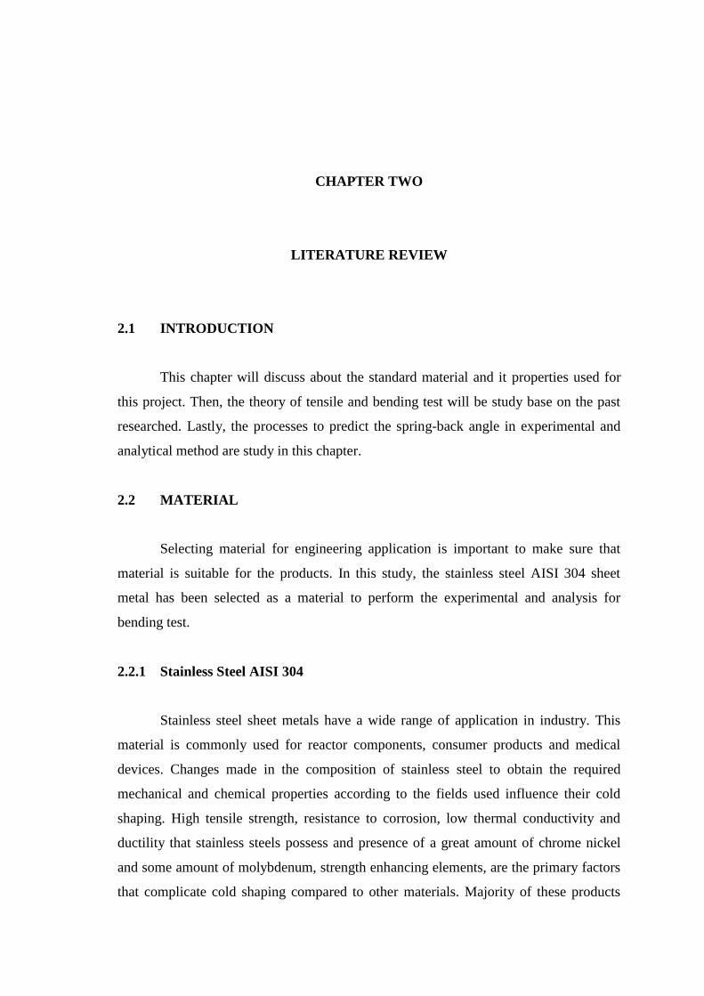
According to Óscar Martín (2010), the chemical composition and the
mechanical properties of the AISI 304 sheets, respectively, are shown in Table 2.3 and
Table 2.4. The sheet thickness is 0.8 mm. The metallographic characterization of
parental metal, which is obtained by using electrolytic etching with oxalic acid, is
according to ASTM A262-91 Practice A.
Table 2.3: Chemical composition of the AISI 304 sheets (wt %)
C Cr Ni Si Mn Mo Al Co
0.08 18.03 8.74 0.426 1.153 0.36 0.003 0.17
Cu Nb Ti V W Fe P S
0.39 0.02 0.004 0.05 0.03 70.48 0.019 0.002
Source: Óscar Martín (2010)
Table 2.4: Mechanical properties of the AISI 304 ASSI sheets
Yield strength
(MPa)
Tensile strength
(MPa)
Total elongation
(%)
Micro hardness
(HV, 100 g)
290 675 70 162
Source: Óscar Martín (2010)
2.3 TENSILE TEST
According to J.R. Davis (2004), tensile test is one of the most common methods
used for evaluating materials. The tensile test is accomplished by gripping the opposite
ends of the specimen within the load frame of a test machine. Tensile force is applied by
the machine, resulting in the gradual elongation and eventual fracture of the test
specimen. During the tensile test process, force-extension data, a quantitative measure
on how the test specimen deforms under the applied tensile force, usually monitored
and recorded. When the method is conducted properly, the result gain by tensile test

7
force-extension data that can quantify several important mechanical properties of a
material such as elastic deformation properties (Young’s modulus and Poisson’s ratio),
yield strength, ultimate tensile strength, ductile properties (elongation and reduction in
area) and strain-hardening characteristics.
2.3.1 Specimen
According to the ASTM standard, the specimen of the tensile test can be divided
into three types where it is plate type specimen, sheet type specimen and round type
specimen. In this project, the test specimen is sheet metal type. Normally, the specimen
has enlarged ends or shoulders for gripping. The cross-sectional area of the gage section
is reduced relative to that of the remainder of the specimen so that deformation and
failure will be localized in this region. The shoulders of the test specimen can be
manufactured in various ways to mate to various grips in the testing machine. Both ends
of the specimens should have sufficient length and a surface condition such that they are
firmly gripped during testing. (J.R. Davis, 2004)
The standard sheet type test specimen according to ASTM standard is shown in
Figure 2.1. This specimen is used for testing metallic materials in the form of sheet,
plate, flat wire, strip, band and hoop ranging in nominal thickness from 0.13 to 19.0
mm. The detail dimension and specification of the tensile test specimen is shown in the
Figure 2.1 and Table 2.5.
Figure 2.1: Examples of rectangular (flat) tensile test specimen
Source: Annual Book of ASTM Standards (2003)

8
Table 2.5: Dimension and specification of the tensile test specimen ASTM E8
Plate type
(1.5 in. wide)
mm
Sheet type
(0.5 in. wide)
mm
Sub-size specimen
(0.25 in. wide)
mm
Gage length 200 ± 0.25 50.0 ± 0.10 25.0 ± 0.08
Width 40 + 3 - 6 12.5 ± 0.25 6.25 ± 0.05
Thickness Thickness of Material
Fillet radius (min.) 13 13 6
Overall length (min.) 450 200 100
Length of reduced section (min.) 225 60 32
Length of grip section (min.) 75 50 32
Width of grip section (approx.) 50 20 10
Source: Annual Book of ASTM Standards (2003)
2.3.2 General Procedures of Tensile Test
After testing specimen has been prepared, the tensile test will be conducted for
test the physical behaviour of the sample. The test specimen will be placed properly at
the grips and if required, extensometers or strain gauge or any other strain measuring
devices can be used with the test specimen for measurement and recording of extension
data. To ensure that the test will run at the proper testing speed and temperature, the
testing should be monitored all the time. The test is started by applying the force to the
test specimen. (J.R. Davis, 2004)
2.4 BENDING TEST
Bending is a common metal forming process used in sheet metal forming to
fabricate curve and angle shaped products of various sizes, such as parts of automobiles,
ships and aircraft. Furthermore, this process also used in making the various consumer
products, such as kitchenware and sanitary products. The bending process concept is
based on engineering science and has a wide variety of applications. Furthermore,

9
bending also features in many sheet metal forming processes, such as the deep drawing
and stamping processes shown in Figure 2.2.
Figure 2.2: Bending in deep drawing process
Source: Sutasn Thipprakmas (2010)
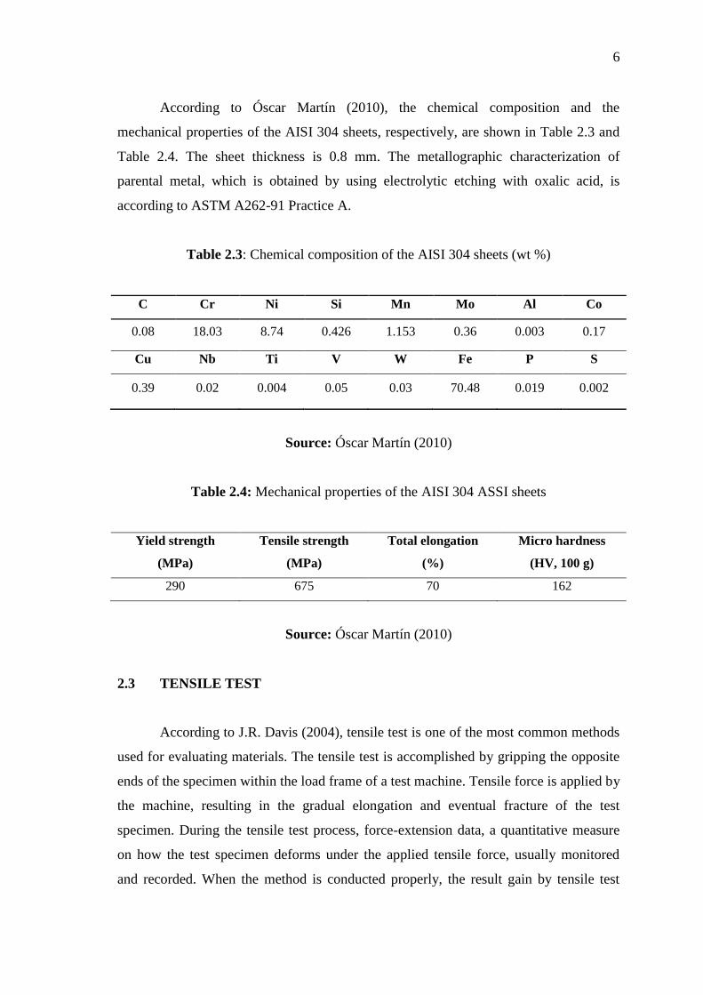
The bending process is divided into two group types which are bending by using
a linear die motion and bending by using a rotating die motion. Bending by using a
linear die motion is the tool moves linearly to bend the work piece. For example, the
wiping die bending and U-bending processes, shown in Figure 2.3 (a). Bending by
using a rotating die motion is a tool moves in rotations to bend the work piece, as shown
in Figure 2.3 (b). The advantages of rotary bending are elimination of the use of a blank
holder, less bending force requirement, and a final bending angle greater than 90
degree.
10
(a) (b)
Figure 2.3: Classification of bending process (a) Linear die motion (b) Rotating die
motion
Source: Sutasn Thipprakmas (2010)
Bending is a manufacturing process where a force, corresponding to a given
punch displacement, acts on the work piece. The work piece is initially bent in an elastic
region. When the process continues, the work piece is deformed by plastic deformation
and changing its shape. The bending load increases until the elastic limit of the material
is exceeded in the bending process. Sheet metal can be formed when the material state
enters the plastic deformation region. In addition, the stress generated in the work piece
is greater than the yield strength but lower than the ultimate tensile strength of the
material. The work piece initially deforms where the bending moment is the greatest.
For example, the process of permanent deformation starts directly underneath the punch
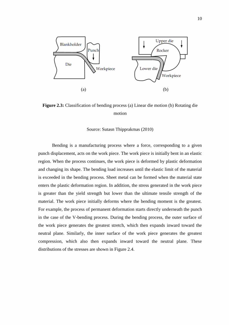
in the case of the V-bending process. During the bending process, the outer surface of
the work piece generates the greatest stretch, which then expands inward toward the
neutral plane. Similarly, the inner surface of the work piece generates the greatest
compression, which also then expands inward toward the neutral plane. These
distributions of the stresses are shown in Figure 2.4.
11
Figure 2.4: Stress distribution in the V-die bending process
Source: Sutasn Thipprakmas (2010)
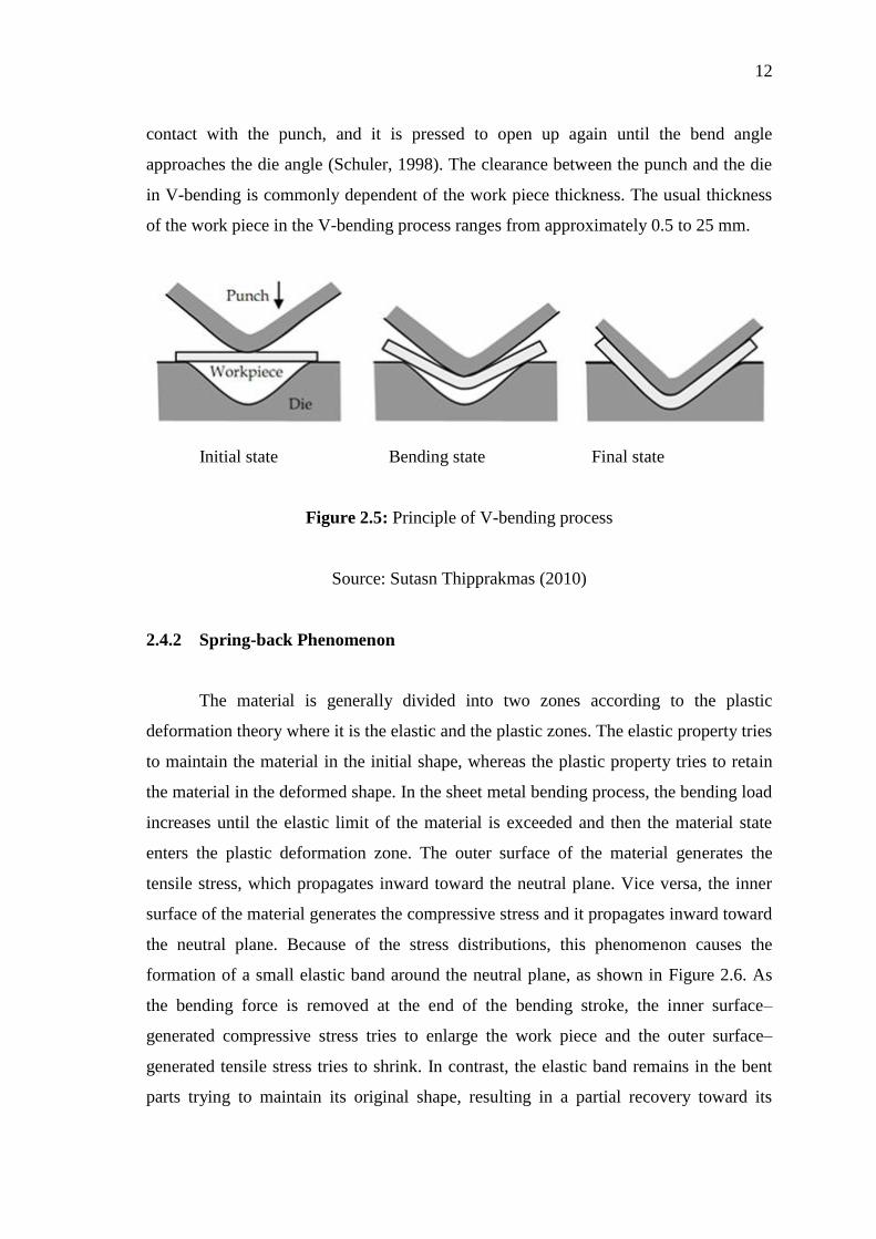
2.4.1 Principle of V-die Bending Process
The V-bending process can be defined as a bending of a V-shaped part in a
single die. The principle of the V-die bending process is shown in Figure 2.5. The work
piece is bent between a V-shaped die and punch. The force acting on the punch causes
punch displacement and make the work piece is bent. The work piece is initially bent as
an elastic deformation. The process continued downward motion by the punch, and
when the stresses exceed the elastic limit, the plastic deformation sets in. This plastic
deformation start occurs on the outer and inner surfaces directly underneath the punch.
The greatest tensile stress is occurred on the outer surface and the greatest compressive
stress is occurred on the inner surface. These stresses decreasingly expand inward
toward the work piece. In addition, crack formation usually occurs on the outer surface
and a wrinkle usually occurs on the inner surface. The initial bending stage is known as
Air bending. Air bending is a process that starts from the moment the punch establishes
contact with the work piece and is completed either when the legs of the work piece
become tangential to the faces of the die or when the smallest internal radius of the
work piece becomes smaller than the radius of the punch. As the process continues,
after completion of air bending, the bending is focused on the three points of the punch
and the two faces of the die. The contact points between the work piece and die are
shifted toward the centreline of the die, and the legs of the work piece try to close
around the punch. As the punch proceeds further, the legs of the work piece establish
12
contact with the punch, and it is pressed to open up again until the bend angle
approaches the die angle (Schuler, 1998). The clearance between the punch and the die
in V-bending is commonly dependent of the work piece thickness. The usual thickness
of the work piece in the V-bending process ranges from approximately 0.5 to 25 mm.
Initial state Bending state Final state
Figure 2.5: Principle of V-bending process
Source: Sutasn Thipprakmas (2010)
2.4.2 Spring-back Phenomenon
The material is generally divided into two zones according to the plastic
deformation theory where it is the elastic and the plastic zones. The elastic property tries
to maintain the material in the initial shape, whereas the plastic property tries to retain
the material in the deformed shape. In the sheet metal bending process, the bending load
increases until the elastic limit of the material is exceeded and then the material state
enters the plastic deformation zone. The outer surface of the material generates the
tensile stress, which propagates inward toward the neutral plane. Vice versa, the inner
surface of the material generates the compressive stress and it propagates inward toward
the neutral plane. Because of the stress distributions, this phenomenon causes the
formation of a small elastic band around the neutral plane, as shown in Figure 2.6. As
the bending force is removed at the end of the bending stroke, the inner surface–
generated compressive stress tries to enlarge the work piece and the outer surface–
generated tensile stress tries to shrink. In contrast, the elastic band remains in the bent
parts trying to maintain its original shape, resulting in a partial recovery toward its
Recommended