Examples of Trussed rafter (monopitch)
CONTENTS
1. ROOF -002, Trussed rafter
1.1. General description, assumptions, materials, loads
1.1.1. Construction type
1.1.2. Design codes
1.1.3. Design methodology
1.1.4. Material properties (truss, purlins)
1.1.5. Distributed roof loads
1.2. Snow load
1.3. Wind loading
1.4. Design of purlins
1.4.1. Serviceability limit state, Control of deflection
1.4.2. Check of purlins, Ultimate limit state of design
1.5. Truss design
1.6. Truss static analysis
1.6.1. Static solutions for unit loads
1.6.2. Internal forces for applied loads
1.6.3. Element end forces for applied loads
1.6.4. Vertical nodal displacements (in mm)
1.6.5. Support reactions (kN)
1.7. Support reactions for load combinations (kN)
1.7.1. Reactions at node : 3 (kN)
1.7.2. Reactions at node : 1 (kN)
1.8. Serviceability limit state
1.8.1. Serviceability limit state, Control of deflection at node 4
1.8.2. Serviceability limit state, Control of deflection in middle of element 1
1.8.3. Serviceability limit state, Control of deflection in middle of element 3
1.9. Characteristic structural natural frequencies (self w eight + permanent loads)
1.9.1. Ultimate limit state, Rafter, elements: 1, 2
1.9.2. Check of cross section Rafter, elements: 1, 2
1.9.3. Ultimate limit state, Tie, elements: 3
1.9.4. Check of cross section Tie, elements: 3
1.9.5. Ultimate limit state, Elements: 4
1.9.6. Check of cross section Elements: 4
1.9.7. Ultimate limit state, Elements: 5
software by RUNET (c) RUNET Norway as12/09/2011 13:56:05
Examples of Trussed rafter (monopitch)
1.9.8. Check of cross section Elements: 5
1.10. Truss connections
1.10.1. Lateral Load-carrying capacity of connections
1.10.2. Ultimate limit state , Design of nailed connection at node : 2
1.10.3. Ultimate limit state , Design of nailed connection at node : 1
1.10.4. Ultimate limit state , Design of nailed connection at node : 4
1.10.5. Ultimate limit state , Design of nailed connection at node : 3
software by RUNET (c) RUNET Norway as12/09/2011 13:56:05
1
2
3
4
4.60
1.80
4.90
2.30 2.30
0.70
2.42
2.47
20.01°
50x125 C30
50x125 C30
50x125 C30
50x125 C30
50x125 C30
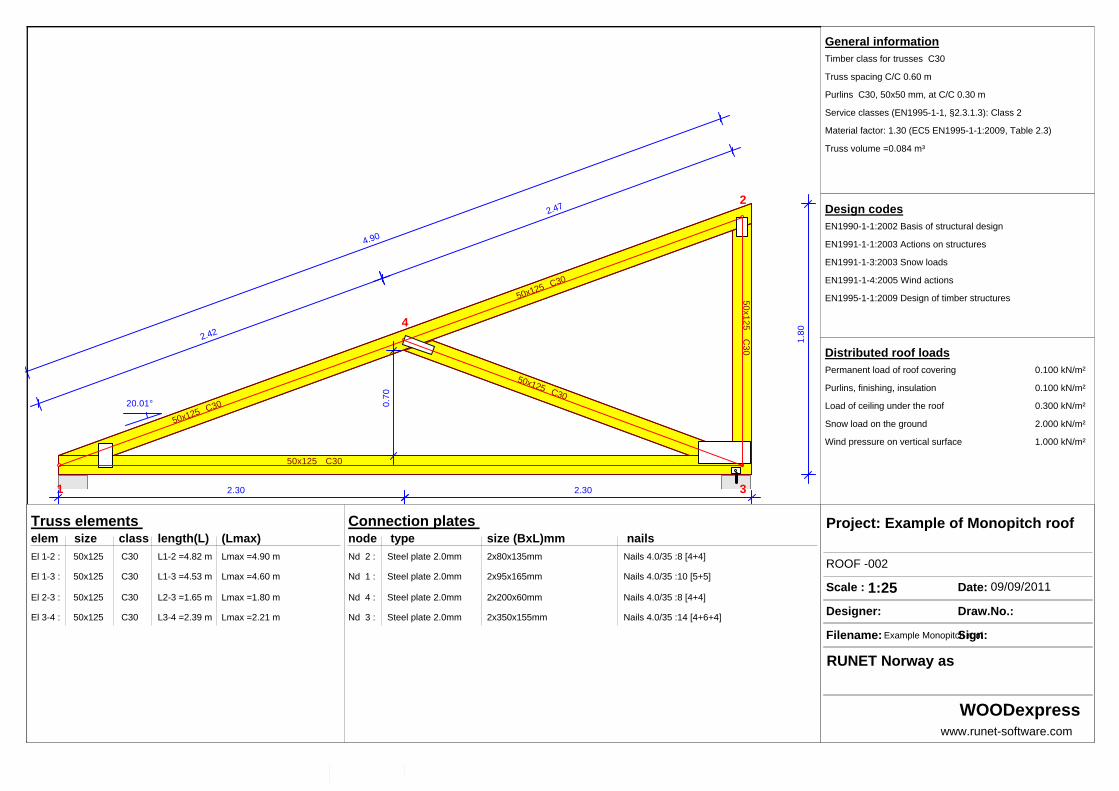
General informationTimber class for trusses C30
Truss spacing C/C 0.60 m
Purlins C30, 50x50 mm, at C/C 0.30 m
Service classes (EN1995-1-1, §2.3.1.3): Class 2
Material factor: 1.30 (EC5 EN1995-1-1:2009, Table 2.3)
Truss volume =0.084 m³
Design codesEN1990-1-1:2002 Basis of structural design
EN1991-1-1:2003 Actions on structures
EN1991-1-3:2003 Snow loads
EN1991-1-4:2005 Wind actions
EN1995-1-1:2009 Design of timber structures
Distributed roof loadsPermanent load of roof covering 0.100 kN/m²
Purlins, finishing, insulation 0.100 kN/m²
Load of ceiling under the roof 0.300 kN/m²
Snow load on the ground 2.000 kN/m²
Wind pressure on vertical surface 1.000 kN/m²
Truss elements elem size class length(L) (Lmax) El 1-2 : 50x125 C30 L1-2 =4.82 m Lmax =4.90 m
El 1-3 : 50x125 C30 L1-3 =4.53 m Lmax =4.60 m
El 2-3 : 50x125 C30 L2-3 =1.65 m Lmax =1.80 m
El 3-4 : 50x125 C30 L3-4 =2.39 m Lmax =2.21 m
Connection plates node type size (BxL)mm nailsNd 2 : Steel plate 2.0mm 2x80x135mm Nails 4.0/35 :8 [4+4]
Nd 1 : Steel plate 2.0mm 2x95x165mm Nails 4.0/35 :10 [5+5]
Nd 4 : Steel plate 2.0mm 2x200x60mm Nails 4.0/35 :8 [4+4]
Nd 3 : Steel plate 2.0mm 2x350x155mm Nails 4.0/35 :14 [4+6+4]
Project: Example of Monopitch roof
ROOF -002
Scale : 1:25 Date: 09/09/2011
Designer: Draw.No.:
Filename: Example Monopitch roofSign:
RUNET Norway as
WOODexpresswww.runet-software.com
Example of Monopitch roof
Example of Monopitch roof
1. ROOF -002
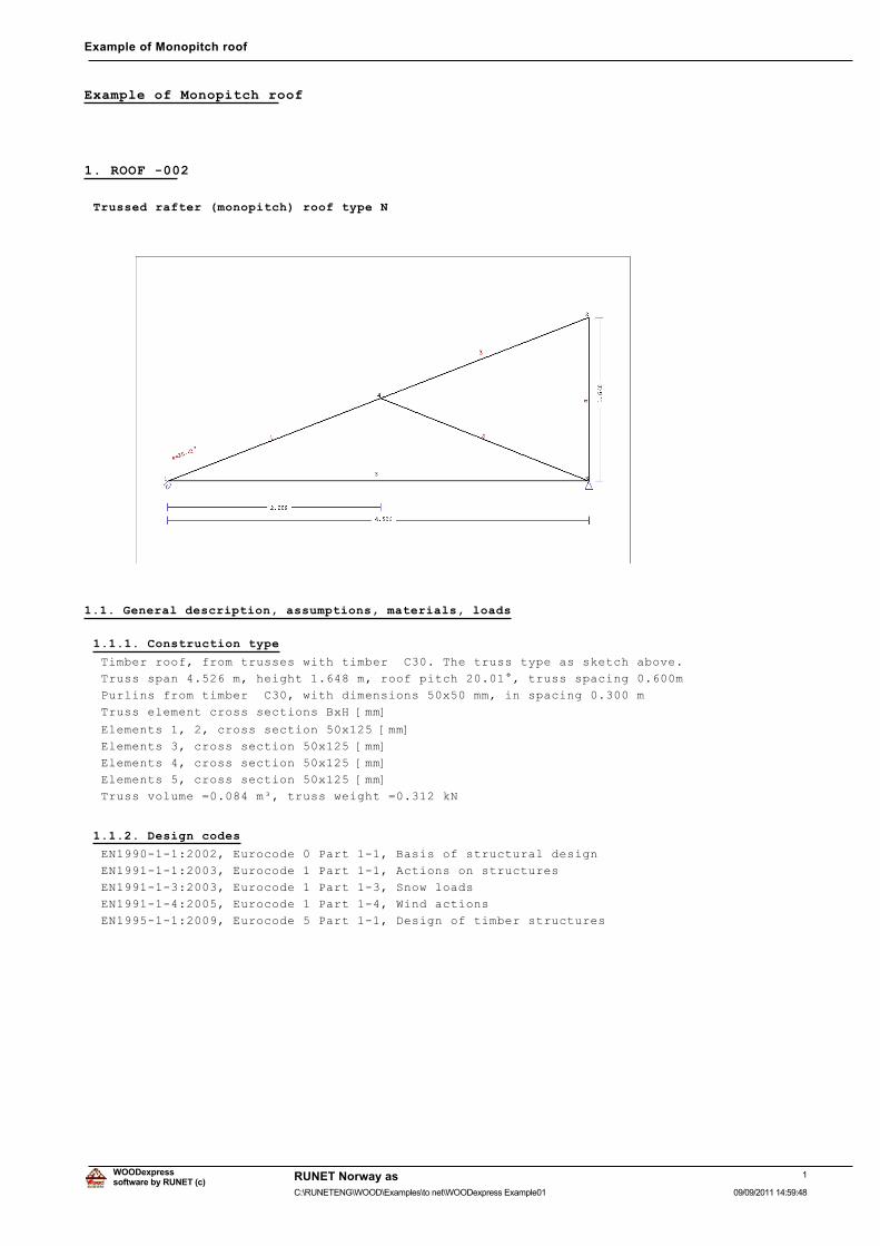
Trussed rafter (monopitch) roof type N
1.1. General description, assumptions, materials, loads
1.1.1. Construction type
Timber roof, from trusses with timber C30. The truss type as sketch above.
Truss span 4.526 m, height 1.648 m, roof pitch 20.01°, truss spacing 0.600m
Purlins from timber C30, with dimensions 50x50 mm, in spacing 0.300 m
Truss element cross sections BxH [mm]
Elements 1, 2, cross section 50x125 [mm]
Elements 3, cross section 50x125 [mm]
Elements 4, cross section 50x125 [mm]
Elements 5, cross section 50x125 [mm]
Truss volume =0.084 m³, truss weight =0.312 kN
1.1.2. Design codes
EN1990-1-1:2002, Eurocode 0 Part 1-1, Basis of structural design
EN1991-1-1:2003, Eurocode 1 Part 1-1, Actions on structures
EN1991-1-3:2003, Eurocode 1 Part 1-3, Snow loads
EN1991-1-4:2005, Eurocode 1 Part 1-4, Wind actions
EN1995-1-1:2009, Eurocode 5 Part 1-1, Design of timber structures
1software by RUNET (c)
RUNET Norway as
09/09/2011 14:59:48C:\RUNETENG\WOOD\Examples\to net\WOODexpress Example01
WOODexpress
Example of Monopitch roof
1.1.3. Design methodology
The internal forces of the roof trusses are computed with finite element analysis. The truss is
considered as a two dimensional frame. The stiffness of the connections is adjusted according to
the selected degree of stiffness. In order to compute the design values for internal forces
in various loading conditions, the internal forces are first computed in unit loading, and then
from their combination the internal forces in various loading conditions are obtained.
All the load combinations according to Eurocode 1 and Eurocode 5 are taken into account,
and the checks are performed in the most unfavourable loading conditions, for combined action,
in ultimate limit state, according to EC5 EN1995-1-1:2009, §6. The connections are designed
as nailed connections with metal plates according to EC5 EN1995-1-1:2009, §8.
The deflections are checked in serviceability limit condition,
according to EC5 EN1995-1-1:2009, §7.
1.1.4. Material properties (truss, purlins) (EC5 EN1995-1-1:2009, §3)
Timber class : C30
Service classes : Class 1, moisture content<=12% (EC5 §2.3.1.3)
0DWHULDO�IDFWRU�Ȗ0 ������(&��7DEOH�����Characteristic material properties for timber
fmk = 30.0 MPa, ft0k = 18.0 MPa, ft90k= 0.4 MPa
fc0k= 23.0 MPa, fc90k= 2.7 MPa, fvk = 4.0 MPa
E0m =12000 MPa, E005 = 8000 MPa, E90m = 400 MPa
*P�� ������03D��ȡN��� ������.J�Pñ
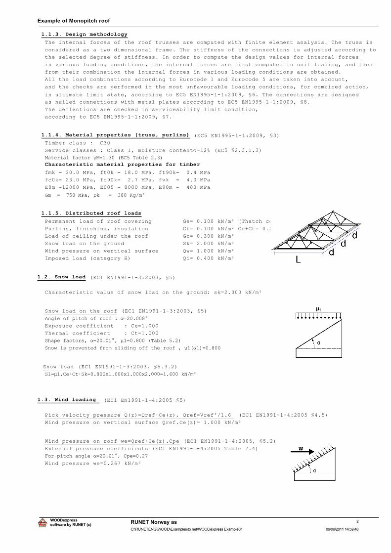
1.1.5. Distributed roof loads
Permanent load of roof covering Ge= 0.100 kN/m² (Thatch cover)
Purlins, finishing, insulation Gt= 0.100 kN/m² Ge+Gt= 0.200 kN/m²
Load of ceiling under the roof Gc= 0.300 kN/m²
Snow load on the ground Sk= 2.000 kN/m²
Wind pressure on vertical surface Qw= 1.000 kN/m²
Imposed load (category H) Qi= 0.400 kN/m²
1.2. Snow load (EC1 EN1991-1-3:2003, §5)
Characteristic value of snow load on the ground: sk=2.000 kN/m²
Snow load on the roof (EC1 EN1991-1-3:2003, §5)
$QJOH�RI�SLWFK�RI�URRI���Į �������
Exposure coefficient : Ce=1.000
Thermal coefficient : Ct=1.000
6KDSH�IDFWRUV��Į ��������ȝ� �������7DEOH�����
6QRZ�LV�SUHYHQWHG�IURP�VOLGLQJ�RII�WKH�URRI���ȝ��Į�� �����
Snow load (EC1 EN1991-1-3:2003, §5.3.2)
6� ȝ��&HÂ&WÂ6N �����[�����[�����[����� ������N1�Pð�
1.3. Wind loading (EC1 EN1991-1-4:2005 §5)
Pick velocity pressure Q(z)=Qref·Ce(z), Qref=Vref²/1.6 (EC1 EN1991-1-4:2005 §4.5)
Wind pressure on vertical surface Qref.Ce(z)= 1.000 kN/m²
Wind pressure on roof we=Qref·Ce(z).Cpe (EC1 EN1991-1-4:2005, §5.2)
External pressure coefficients (EC1 EN1991-1-4:2005 Table 7.4)
)RU�SLWFK�DQJOH�Į ��������&SH ����
Wind pressure we=0.267 kN/m²
2software by RUNET (c)
RUNET Norway as
09/09/2011 14:59:48C:\RUNETENG\WOOD\Examples\to net\WOODexpress Example01
WOODexpress
Example of Monopitch roof
1.4. Design of purlins
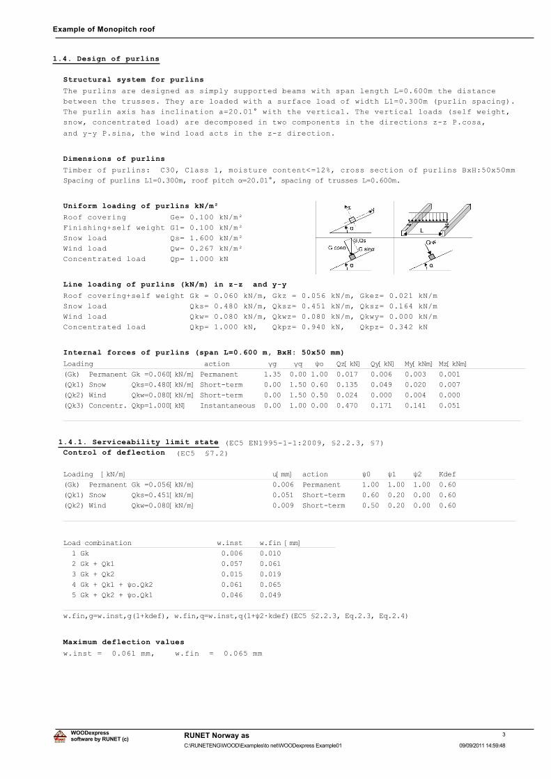
Structural system for purlins
The purlins are designed as simply supported beams with span length L=0.600m the distance
between the trusses. They are loaded with a surface load of width L1=0.300m (purlin spacing).
The purlin axis has inclination a=20.01° with the vertical. The vertical loads (self weight,
snow, concentrated load) are decomposed in two components in the directions z-z P.cosa,
and y-y P.sina, the wind load acts in the z-z direction.
Dimensions of purlins
Timber of purlins: C30, Class 1, moisture content<=12%, cross section of purlins BxH:50x50mm
6SDFLQJ�RI�SXUOLQV�/� �����P��URRI�SLWFK�Į ��������VSDFLQJ�RI�WUXVVHV�/ �����P�
Uniform loading of purlins kN/m²
Roof covering Ge= 0.100 kN/m²
Finishing+self weight G1= 0.100 kN/m²
Snow load Qs= 1.600 kN/m²
Wind load Qw= 0.267 kN/m²
Concentrated load Qp= 1.000 kN
Line loading of purlins (kN/m) in z-z and y-y
Roof covering+self weight Gk = 0.060 kN/m, Gkz = 0.056 kN/m, Gkez= 0.021 kN/m
Snow load Qks= 0.480 kN/m, Qksz= 0.451 kN/m, Qksz= 0.164 kN/m
Wind load Qkw= 0.080 kN/m, Qkwz= 0.080 kN/m, Qkwy= 0.000 kN/m
Concentrated load Qkp= 1.000 kN, Qkpz= 0.940 kN, Qkpz= 0.342 kN
Internal forces of purlins (span L=0.600 m, BxH: 50x50 mm)
/RDGLQJ��������������������������DFWLRQ���������ȖJ����ȖT���ȥR���4]>N1@��4\>N1@��0\>N1P@�0]>N1P@
�*N���3HUPDQHQW�*N� �����>N1�P@�3HUPDQHQW�����������������������������������������������������
�4N���6QRZ������4NV �����>N1�P@�6KRUW�WHUP����������������������������������������������������
�4N���:LQG������4NZ �����>N1�P@�6KRUW�WHUP����������������������������������������������������
�4N���&RQFHQWU��4NS �����>N1@���,QVWDQWDQHRXV�������������������������������������������������
����������������������������������������������������������������������������������������������
1.4.1. Serviceability limit state (EC5 EN1995-1-1:2009, §2.2.3, §7)Control of deflection (EC5 §7.2)
/RDGLQJ��>N1�P@����������������������������������X>PP@��DFWLRQ��������ȥ�����ȥ�����ȥ�����.GHI�
�*N���3HUPDQHQW�*N� �����>N1�P@�������������������������3HUPDQHQW����������������������������
�4N���6QRZ������4NV �����>N1�P@�������������������������6KRUW�WHUP���������������������������
�4N���:LQG������4NZ �����>N1�P@�������������������������6KRUW�WHUP���������������������������
���������������������������������������������������������������������������������������������
/RDG�FRPELQDWLRQ��������������������Z�LQVW����Z�ILQ�>PP@
����*N����������������������������������������������
����*N���4N�����������������������������������������
����*N���4N�����������������������������������������
����*N���4N����ȥR�4N��������������������������������
����*N���4N����ȥR�4N��������������������������������
����������������������������������������������������
Z�ILQ�J Z�LQVW�J���NGHI���Z�ILQ�T Z�LQVW�T���ȥ�ÂNGHI��(&����������(T������(T�����
Maximum deflection values
w.inst = 0.061 mm, w.fin = 0.065 mm
3software by RUNET (c)
RUNET Norway as
09/09/2011 14:59:48C:\RUNETENG\WOOD\Examples\to net\WOODexpress Example01
WOODexpress
Example of Monopitch roof
Check according to EC5 EN1995-1-1:2009 §7.2, Tab.7.2
Final deflections
w.inst = 0.061 mm < L/300=600/300= 2.000 mm
w.net,fin = 0.065 mm < L/250=600/250= 2.400 mm
w.fin = 0.065 mm < L/150=600/150= 4.000 mm
The check is satisfied
1.4.2. Check of purlins, Ultimate limit state of design (EC5 EN1995-1-1:2009, §6)
�/�&����/RDG�FRPELQDWLRQ����������GXUDWLRQ�FODVV�����NPRG����4]�.PRG��4\�.PRG��0\�.PRG��0]�.PRG
����ȖJ�*N����������������������������3HUPDQHQW������������������������������������������������
����ȖJ�*N���ȖT�4N��������������������6KRUW�WHUP�����������������������������������������������
����ȖJ�*N���ȖT�4N��������������������6KRUW�WHUP�����������������������������������������������
����ȖJ�*N���ȖT�4N��������������������,QVWDQWDQHRXV��������������������������������������������
����ȖJ�*N���ȖT�4N����ȖT�ȥR�4N��������6KRUW�WHUP�����������������������������������������������
����ȖJ�*N���ȖT�4N����ȖT�ȥR�4N��������6KRUW�WHUP�����������������������������������������������
����0D[LPXP�YDOXHV����������������������������������������������������������������������������
����������������������������������������������������������������������������������������������
Purlin, load combination No 4
Shear, Fv=0.493 kN (EC5 §6.1.7)
Rectangular cross section, bef=0.67x50=34 mm, h=50 mm, A= 1 700 mm²
0RGLILFDWLRQ�IDFWRU�.PRG ������7DEOH�������PDWHULDO�IDFWRU�Ȗ0 ������7DEOH�����
IYN �����1�PPð��IYG .PRGÂIYN�Ȗ0 ����[��������� ����1�PPð��(&��(T������
)Y ������N1��IJY�G ����)Y�G�$QHWWR ����[����[���������� ����1�PPð�������1�PPð IY�G��(T������
The check is satisfied
Purlin, load combination No 4
Shear, Fv=0.179 kN (EC5 §6.1.7)
Rectangular cross section, bef=0.67x50=34 mm, h=50 mm, A= 1 700 mm²
0RGLILFDWLRQ�IDFWRU�.PRG ������7DEOH�������PDWHULDO�IDFWRU�Ȗ0 ������7DEOH�����
IYN �����1�PPð��IYG .PRGÂIYN�Ȗ0 ����[��������� ����1�PPð��(&��(T������
)Y ������N1��IJY�G ����)Y�G�$QHWWR ����[����[���������� ����1�PPð�������1�PPð IY�G��(T������
The check is satisfied
Purlin, load combination No 4
Bending, Myd=0.144 kNm, Mzd=0.053 kNm (EC5 §6.1.6)
Rectangular cross section, b=50mm, h=50mm, A=2.500E+003mm², Wy=2.083E+004mm³, Wz=2.083E+004mm³
0RGLILFDWLRQ�IDFWRU�.PRG ������7DEOH�������PDWHULDO�IDFWRU�Ȗ0 ������7DEOH�����
IP\N ������1�PPð��IP\G .PRGÂIP\N�Ȗ0 ����[���������� �����1�PPð
IP]N ������1�PPð��IP]G .PRGÂIP]N�Ȗ0 ����[���������� �����1�PPð
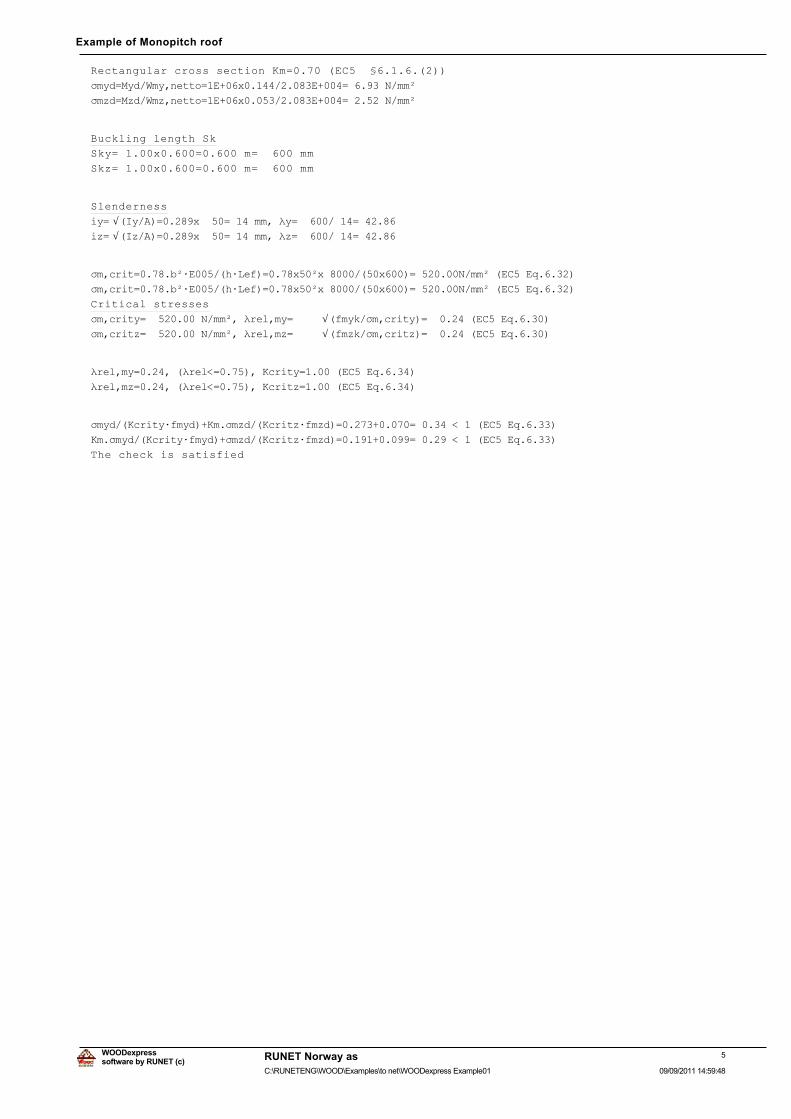
Rectangular cross section Km=0.70 (EC5 §6.1.6.(2))
ıP\G 0\G�:P\�QHWWR �(���[�����������(���� ������1�PPð
ıP]G 0]G�:P]�QHWWR �(���[�����������(���� ������1�PPð
ıP\G�IP\G�.P�ıP]G�IP]G ����������� �����������(&��(T������
.P�ıP\G�IP\G�ıP]G�IP]G ����������� �����������(&��(T������
The check is satisfied
Purlin, load combination No 4
Lateral torsional stability of beams, Myd=0.144 kNm, Mzd=0.053 kNm (EC5 §6.3.3)
Rectangular cross section, b=50mm, h=50mm, A=2.500E+003mm², Wy=2.083E+004mm³, Wz=2.083E+004mm³
0RGLILFDWLRQ�IDFWRU�.PRG ������7DEOH�������PDWHULDO�IDFWRU�Ȗ0 ������7DEOH�����
IF�N ������1�PPð��IF�G .PRGÂIF�N�Ȗ0 ����[���������� �����1�PPð
IP\N ������1�PPð��IP\G .PRGÂIP\N�Ȗ0 ����[���������� �����1�PPð
IP]N ������1�PPð��IP]G .PRGÂIP]N�Ȗ0 ����[���������� �����1�PPð
4software by RUNET (c)
RUNET Norway as
09/09/2011 14:59:48C:\RUNETENG\WOOD\Examples\to net\WOODexpress Example01
WOODexpress
Example of Monopitch roof
Rectangular cross section Km=0.70 (EC5 §6.1.6.(2))
ıP\G 0\G�:P\�QHWWR �(���[�����������(���� ������1�PPð
ıP]G 0]G�:P]�QHWWR �(���[�����������(���� ������1�PPð
Buckling length Sk
Sky= 1.00x0.600=0.600 m= 600 mm
Skz= 1.00x0.600=0.600 m= 600 mm
Slenderness
L\ Ö�,\�$� �����[���� ����PP��Ȝ\ ��������� ������L] Ö�,]�$� �����[���� ����PP��Ȝ] ��������� ������
ıP�FULW �����EðÂ(�����KÂ/HI� ����[��ð[���������[���� �������1�PPð��(&��(T������
ıP�FULW �����EðÂ(�����KÂ/HI� ����[��ð[���������[���� �������1�PPð��(&��(T������
Critical stresses
ıP�FULW\ ���������1�PPð��ȜUHO�P\ Ö�IP\N�ıP�FULW\� ��������(&��(T������ıP�FULW] ���������1�PPð��ȜUHO�P] Ö�IP]N�ıP�FULW]� ��������(&��(T������
ȜUHO�P\ �������ȜUHO� �������.FULW\ ������(&��(T������
ȜUHO�P] �������ȜUHO� �������.FULW] ������(&��(T������
ıP\G��.FULW\ÂIP\G��.P�ıP]G��.FULW]ÂIP]G� ����������� �����������(&��(T������
.P�ıP\G��.FULW\ÂIP\G��ıP]G��.FULW]ÂIP]G� ����������� �����������(&��(T������
The check is satisfied
5software by RUNET (c)
RUNET Norway as
09/09/2011 14:59:48C:\RUNETENG\WOOD\Examples\to net\WOODexpress Example01
WOODexpress
Example of Monopitch roof
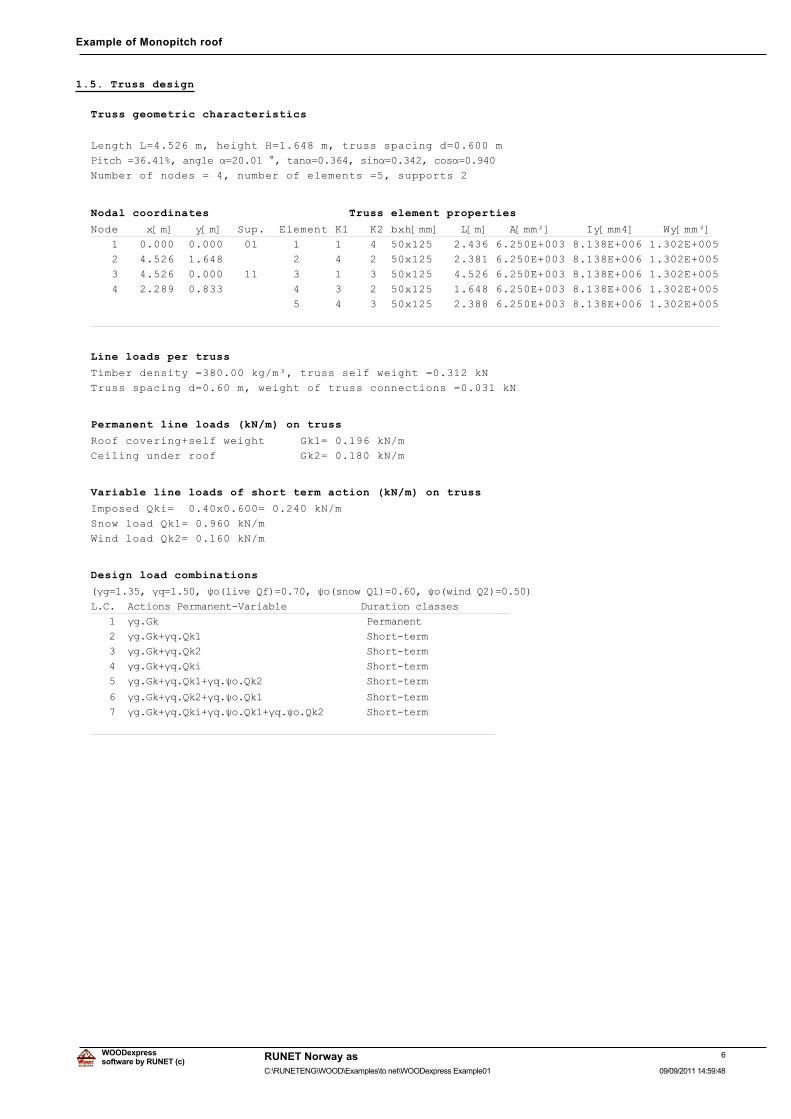
1.5. Truss design
Truss geometric characteristics
Length L=4.526 m, height H=1.648 m, truss spacing d=0.600 m
3LWFK� ��������DQJOH�Į ���������WDQĮ �������VLQĮ �������FRVĮ �����
Number of nodes = 4, number of elements =5, supports 2
Nodal coordinates Truss element properties
Node x[m] y[m] Sup. Element K1 K2 bxh[mm] L[m] A[mm²] Iy[mm4] Wy[mm³]
1 0.000 0.000 01 1 1 4 50x125 2.436 6.250E+003 8.138E+006 1.302E+005
2 4.526 1.648 2 4 2 50x125 2.381 6.250E+003 8.138E+006 1.302E+005
3 4.526 0.000 11 3 1 3 50x125 4.526 6.250E+003 8.138E+006 1.302E+005
4 2.289 0.833 4 3 2 50x125 1.648 6.250E+003 8.138E+006 1.302E+005
5 4 3 50x125 2.388 6.250E+003 8.138E+006 1.302E+005
Line loads per truss
Timber density =380.00 kg/m³, truss self weight =0.312 kN
Truss spacing d=0.60 m, weight of truss connections =0.031 kN
Permanent line loads (kN/m) on truss
Roof covering+self weight Gk1= 0.196 kN/m
Ceiling under roof Gk2= 0.180 kN/m
Variable line loads of short term action (kN/m) on truss
Imposed Qki= 0.40x0.600= 0.240 kN/m
Snow load Qk1= 0.960 kN/m
Wind load Qk2= 0.160 kN/m
Design load combinations
�ȖJ ������ȖT ������ȥR�OLYH�4I� ������ȥR�VQRZ�4�� ������ȥR�ZLQG�4�� �����
/�&���$FWLRQV�3HUPDQHQW�9DULDEOH������������'XUDWLRQ�FODVVHV
������ȖJ�*N����������������������������������3HUPDQHQW����
������ȖJ�*N�ȖT�4N����������������������������6KRUW�WHUP���
������ȖJ�*N�ȖT�4N����������������������������6KRUW�WHUP���
������ȖJ�*N�ȖT�4NL���������������������������6KRUW�WHUP���
������ȖJ�*N�ȖT�4N��ȖT�ȥR�4N������������������6KRUW�WHUP���
������ȖJ�*N�ȖT�4N��ȖT�ȥR�4N������������������6KRUW�WHUP���
������ȖJ�*N�ȖT�4NL�ȖT�ȥR�4N��ȖT�ȥR�4N��������6KRUW�WHUP���
����������������������������������������������������������
6software by RUNET (c)
RUNET Norway as
09/09/2011 14:59:48C:\RUNETENG\WOOD\Examples\to net\WOODexpress Example01
WOODexpress
Example of Monopitch roof
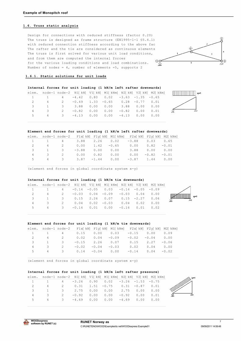
1.6. Truss static analysis
Design for connections with reduced stiffness (factor 0.20)
The truss is designed as frame structure (EN1995-1-1 §5.4.1)
with reduced connection stiffness according to the above factor
The rafter and the tie are considered as continuous elements.
The truss is first solved for various unit load conditions,
and from them are computed the internal forces
for the various loading conditions and load combinations.
Number of nodes = 4, number of elements =5, supports 2
1.6.1. Static solutions for unit loads
Internal forces for unit loading (1 kN/m left rafter downwards)
elem. node-1 node-2 N1[kN] V1[kN] M1[kNm] N2[kN] V2[kN] M2[kNm]
1 1 4 -4.42 0.80 0.02 -3.63 -1.35 -0.65
2 4 2 -0.49 1.33 -0.65 0.28 -0.77 0.01
3 1 3 3.88 0.00 0.00 3.88 0.00 0.00
4 3 2 -0.82 0.00 0.00 -0.82 0.00 0.01
5 4 3 -4.13 0.00 0.00 -4.13 0.00 0.00
Element end forces for unit loading (1 kN/m left rafter downwards)
elem. node-1 node-2 F1x[kN] F1y[kN] M1[kNm] F2x[kN] F2y[kN] M2[kNm]
1 1 4 3.88 2.26 0.02 -3.88 0.03 0.65
2 4 2 0.00 1.42 -0.65 0.00 0.82 -0.01
3 1 3 -3.88 0.00 0.00 3.88 0.00 0.00
4 3 2 0.00 0.82 0.00 0.00 -0.82 -0.01
5 4 3 3.87 -1.44 0.00 -3.87 1.44 0.00
(element end forces in global coordinate system x-y)
Internal forces for unit loading (1 kN/m tie downwards)
elem. node-1 node-2 N1[kN] V1[kN] M1[kNm] N2[kN] V2[kN] M2[kNm]
1 1 4 -0.14 -0.05 0.03 -0.14 -0.05 -0.09
2 4 2 -0.03 0.04 -0.09 -0.03 0.04 0.00
3 1 3 0.15 2.26 0.07 0.15 -2.27 0.06
4 3 2 0.04 0.02 -0.03 0.04 0.02 0.00
5 4 3 -0.14 0.01 0.00 -0.14 0.01 0.02
Element end forces for unit loading (1 kN/m tie downwards)
elem. node-1 node-2 F1x[kN] F1y[kN] M1[kNm] F2x[kN] F2y[kN] M2[kNm]
1 1 4 0.15 0.00 0.03 -0.15 0.00 0.09
2 4 2 0.02 0.04 -0.09 -0.02 -0.04 0.00
3 1 3 -0.15 2.26 0.07 0.15 2.27 -0.06
4 3 2 -0.02 -0.04 -0.03 0.02 0.04 0.00
5 4 3 0.14 -0.04 0.00 -0.14 0.04 -0.02
(element end forces in global coordinate system x-y)
Internal forces for unit loading (1 kN/m left rafter pressure)
elem. node-1 node-2 N1[kN] V1[kN] M1[kNm] N2[kN] V2[kN] M2[kNm]
1 1 4 -3.26 0.90 0.02 -3.26 -1.53 -0.75
2 4 2 0.31 1.51 -0.75 0.31 -0.87 0.01
3 1 3 2.75 0.00 0.00 2.75 0.00 0.00
4 3 2 -0.92 0.00 0.00 -0.92 0.00 0.01
5 4 3 -4.69 0.00 0.00 -4.69 0.00 0.00
7software by RUNET (c)
RUNET Norway as
09/09/2011 14:59:48C:\RUNETENG\WOOD\Examples\to net\WOODexpress Example01
WOODexpress
Example of Monopitch roof
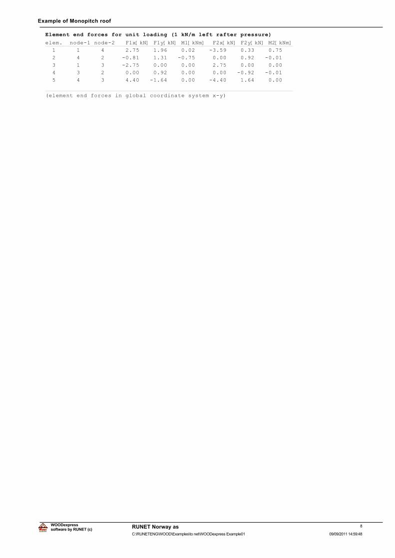
Element end forces for unit loading (1 kN/m left rafter pressure)
elem. node-1 node-2 F1x[kN] F1y[kN] M1[kNm] F2x[kN] F2y[kN] M2[kNm]
1 1 4 2.75 1.96 0.02 -3.59 0.33 0.75
2 4 2 -0.81 1.31 -0.75 0.00 0.92 -0.01
3 1 3 -2.75 0.00 0.00 2.75 0.00 0.00
4 3 2 0.00 0.92 0.00 0.00 -0.92 -0.01
5 4 3 4.40 -1.64 0.00 -4.40 1.64 0.00
(element end forces in global coordinate system x-y)
8software by RUNET (c)
RUNET Norway as
09/09/2011 14:59:48C:\RUNETENG\WOOD\Examples\to net\WOODexpress Example01
WOODexpress
Example of Monopitch roof
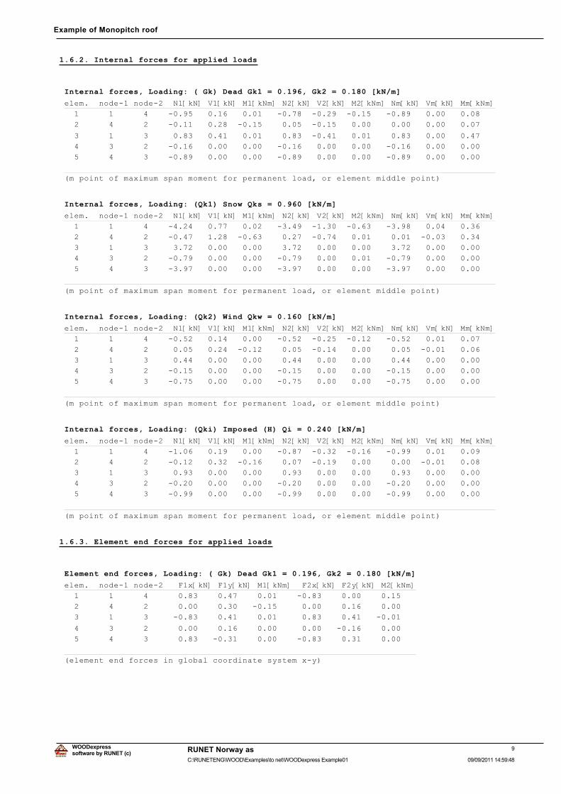
1.6.2. Internal forces for applied loads
Internal forces, Loading: ( Gk) Dead Gk1 = 0.196, Gk2 = 0.180 [kN/m]
elem. node-1 node-2 N1[kN] V1[kN] M1[kNm] N2[kN] V2[kN] M2[kNm] Nm[kN] Vm[kN] Mm[kNm]
1 1 4 -0.95 0.16 0.01 -0.78 -0.29 -0.15 -0.89 0.00 0.08
2 4 2 -0.11 0.28 -0.15 0.05 -0.15 0.00 0.00 0.00 0.07
3 1 3 0.83 0.41 0.01 0.83 -0.41 0.01 0.83 0.00 0.47
4 3 2 -0.16 0.00 0.00 -0.16 0.00 0.00 -0.16 0.00 0.00
5 4 3 -0.89 0.00 0.00 -0.89 0.00 0.00 -0.89 0.00 0.00
(m point of maximum span moment for permanent load, or element middle point)
Internal forces, Loading: (Qk1) Snow Qks = 0.960 [kN/m]
elem. node-1 node-2 N1[kN] V1[kN] M1[kNm] N2[kN] V2[kN] M2[kNm] Nm[kN] Vm[kN] Mm[kNm]
1 1 4 -4.24 0.77 0.02 -3.49 -1.30 -0.63 -3.98 0.04 0.36
2 4 2 -0.47 1.28 -0.63 0.27 -0.74 0.01 0.01 -0.03 0.34
3 1 3 3.72 0.00 0.00 3.72 0.00 0.00 3.72 0.00 0.00
4 3 2 -0.79 0.00 0.00 -0.79 0.00 0.01 -0.79 0.00 0.00
5 4 3 -3.97 0.00 0.00 -3.97 0.00 0.00 -3.97 0.00 0.00
(m point of maximum span moment for permanent load, or element middle point)
Internal forces, Loading: (Qk2) Wind Qkw = 0.160 [kN/m]
elem. node-1 node-2 N1[kN] V1[kN] M1[kNm] N2[kN] V2[kN] M2[kNm] Nm[kN] Vm[kN] Mm[kNm]
1 1 4 -0.52 0.14 0.00 -0.52 -0.25 -0.12 -0.52 0.01 0.07
2 4 2 0.05 0.24 -0.12 0.05 -0.14 0.00 0.05 -0.01 0.06
3 1 3 0.44 0.00 0.00 0.44 0.00 0.00 0.44 0.00 0.00
4 3 2 -0.15 0.00 0.00 -0.15 0.00 0.00 -0.15 0.00 0.00
5 4 3 -0.75 0.00 0.00 -0.75 0.00 0.00 -0.75 0.00 0.00
(m point of maximum span moment for permanent load, or element middle point)
Internal forces, Loading: (Qki) Imposed (H) Qi = 0.240 [kN/m]
elem. node-1 node-2 N1[kN] V1[kN] M1[kNm] N2[kN] V2[kN] M2[kNm] Nm[kN] Vm[kN] Mm[kNm]
1 1 4 -1.06 0.19 0.00 -0.87 -0.32 -0.16 -0.99 0.01 0.09
2 4 2 -0.12 0.32 -0.16 0.07 -0.19 0.00 0.00 -0.01 0.08
3 1 3 0.93 0.00 0.00 0.93 0.00 0.00 0.93 0.00 0.00
4 3 2 -0.20 0.00 0.00 -0.20 0.00 0.00 -0.20 0.00 0.00
5 4 3 -0.99 0.00 0.00 -0.99 0.00 0.00 -0.99 0.00 0.00
(m point of maximum span moment for permanent load, or element middle point)
1.6.3. Element end forces for applied loads
Element end forces, Loading: ( Gk) Dead Gk1 = 0.196, Gk2 = 0.180 [kN/m]
elem. node-1 node-2 F1x[kN] F1y[kN] M1[kNm] F2x[kN] F2y[kN] M2[kNm]
1 1 4 0.83 0.47 0.01 -0.83 0.00 0.15
2 4 2 0.00 0.30 -0.15 0.00 0.16 0.00
3 1 3 -0.83 0.41 0.01 0.83 0.41 -0.01
4 3 2 0.00 0.16 0.00 0.00 -0.16 0.00
5 4 3 0.83 -0.31 0.00 -0.83 0.31 0.00
(element end forces in global coordinate system x-y)
9software by RUNET (c)
RUNET Norway as
09/09/2011 14:59:48C:\RUNETENG\WOOD\Examples\to net\WOODexpress Example01
WOODexpress
Example of Monopitch roof
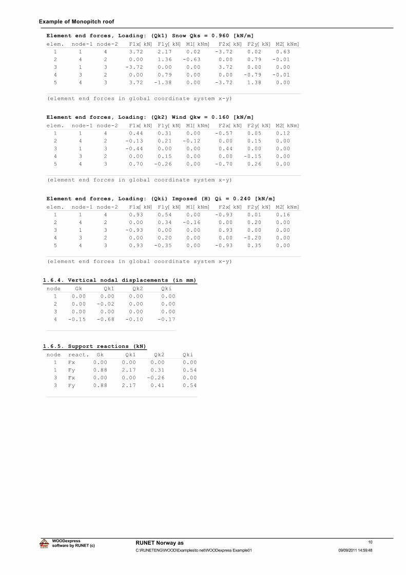
Element end forces, Loading: (Qk1) Snow Qks = 0.960 [kN/m]
elem. node-1 node-2 F1x[kN] F1y[kN] M1[kNm] F2x[kN] F2y[kN] M2[kNm]
1 1 4 3.72 2.17 0.02 -3.72 0.02 0.63
2 4 2 0.00 1.36 -0.63 0.00 0.79 -0.01
3 1 3 -3.72 0.00 0.00 3.72 0.00 0.00
4 3 2 0.00 0.79 0.00 0.00 -0.79 -0.01
5 4 3 3.72 -1.38 0.00 -3.72 1.38 0.00
(element end forces in global coordinate system x-y)
Element end forces, Loading: (Qk2) Wind Qkw = 0.160 [kN/m]
elem. node-1 node-2 F1x[kN] F1y[kN] M1[kNm] F2x[kN] F2y[kN] M2[kNm]
1 1 4 0.44 0.31 0.00 -0.57 0.05 0.12
2 4 2 -0.13 0.21 -0.12 0.00 0.15 0.00
3 1 3 -0.44 0.00 0.00 0.44 0.00 0.00
4 3 2 0.00 0.15 0.00 0.00 -0.15 0.00
5 4 3 0.70 -0.26 0.00 -0.70 0.26 0.00
(element end forces in global coordinate system x-y)
Element end forces, Loading: (Qki) Imposed (H) Qi = 0.240 [kN/m]
elem. node-1 node-2 F1x[kN] F1y[kN] M1[kNm] F2x[kN] F2y[kN] M2[kNm]
1 1 4 0.93 0.54 0.00 -0.93 0.01 0.16
2 4 2 0.00 0.34 -0.16 0.00 0.20 0.00
3 1 3 -0.93 0.00 0.00 0.93 0.00 0.00
4 3 2 0.00 0.20 0.00 0.00 -0.20 0.00
5 4 3 0.93 -0.35 0.00 -0.93 0.35 0.00
(element end forces in global coordinate system x-y)
1.6.4. Vertical nodal displacements (in mm)
node Gk Qk1 Qk2 Qki
1 0.00 0.00 0.00 0.00
2 0.00 -0.02 0.00 0.00
3 0.00 0.00 0.00 0.00
4 -0.15 -0.68 -0.10 -0.17
1.6.5. Support reactions (kN)
node react. Gk Qk1 Qk2 Qki
1 Fx 0.00 0.00 0.00 0.00
1 Fy 0.88 2.17 0.31 0.54
3 Fx 0.00 0.00 -0.26 0.00
3 Fy 0.88 2.17 0.41 0.54
10software by RUNET (c)
RUNET Norway as
09/09/2011 14:59:48C:\RUNETENG\WOOD\Examples\to net\WOODexpress Example01
WOODexpress
Example of Monopitch roof
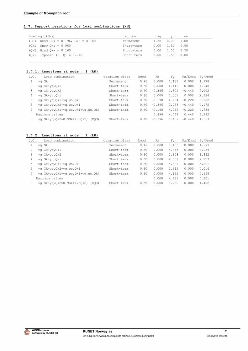
1.7. Support reactions for load combinations (kN)
/RDGLQJ�>N1�P@������������������������������������DFWLRQ�����������ȖJ�����ȖT�����ȥR�
��*N��'HDG�*N�� ��������*N�� ��������������������3HUPDQHQW��������������������������
�4N���6QRZ�4NV� ���������������������������������6KRUW�WHUP�������������������������
�4N���:LQG�4NZ� ���������������������������������6KRUW�WHUP�������������������������
�4NL��,PSRVHG��+��4L� ���������������������������6KRUW�WHUP�������������������������
������������������������������������������������������������������������������������
1.7.1. Reactions at node : 3 (kN)
/�&�����/RDG�FRPELQDWLRQ���������������GXUDWLRQ�FODVV����NPRG�����)[������)\����)[�.PRG��)\�.PRG
�����ȖJ�*N��������������������������������3HUPDQHQW���������������������������������������������
�����ȖJ�*N�ȖT�4N��������������������������6KRUW�WHUP��������������������������������������������
�����ȖJ�*N�ȖT�4N��������������������������6KRUW�WHUP��������������������������������������������
�����ȖJ�*N�ȖT�4NL�������������������������6KRUW�WHUP��������������������������������������������
�����ȖJ�*N�ȖT�4N��ȖT�ȥR�4N����������������6KRUW�WHUP��������������������������������������������
�����ȖJ�*N�ȖT�4N��ȖT�ȥR�4N����������������6KRUW�WHUP��������������������������������������������
�����ȖJ�*N�ȖT�4NL�ȖT�ȥR�4N��ȖT�ȥR�4N������6KRUW�WHUP��������������������������������������������
����0D[LPXP�YDOXHV�����������������������������������������������������������������������������
�����ȖJ�*N�ȖT�4N� ���*N����4N����(48������6KRUW�WHUP��������������������������������������������
������������������������������������������������������������������������������������������������
1.7.2. Reactions at node : 1 (kN)
/�&�����/RDG�FRPELQDWLRQ���������������GXUDWLRQ�FODVV����NPRG�����)[������)\����)[�.PRG��)\�.PRG
�����ȖJ�*N��������������������������������3HUPDQHQW���������������������������������������������
�����ȖJ�*N�ȖT�4N��������������������������6KRUW�WHUP��������������������������������������������
�����ȖJ�*N�ȖT�4N��������������������������6KRUW�WHUP��������������������������������������������
�����ȖJ�*N�ȖT�4NL�������������������������6KRUW�WHUP��������������������������������������������
�����ȖJ�*N�ȖT�4N��ȖT�ȥR�4N����������������6KRUW�WHUP��������������������������������������������
�����ȖJ�*N�ȖT�4N��ȖT�ȥR�4N����������������6KRUW�WHUP��������������������������������������������
�����ȖJ�*N�ȖT�4NL�ȖT�ȥR�4N��ȖT�ȥR�4N������6KRUW�WHUP��������������������������������������������
����0D[LPXP�YDOXHV�����������������������������������������������������������������������������
�����ȖJ�*N�ȖT�4N� ���*N����4N����(48������6KRUW�WHUP��������������������������������������������
������������������������������������������������������������������������������������������������
11software by RUNET (c)
RUNET Norway as
09/09/2011 14:59:48C:\RUNETENG\WOOD\Examples\to net\WOODexpress Example01
WOODexpress
Example of Monopitch roof
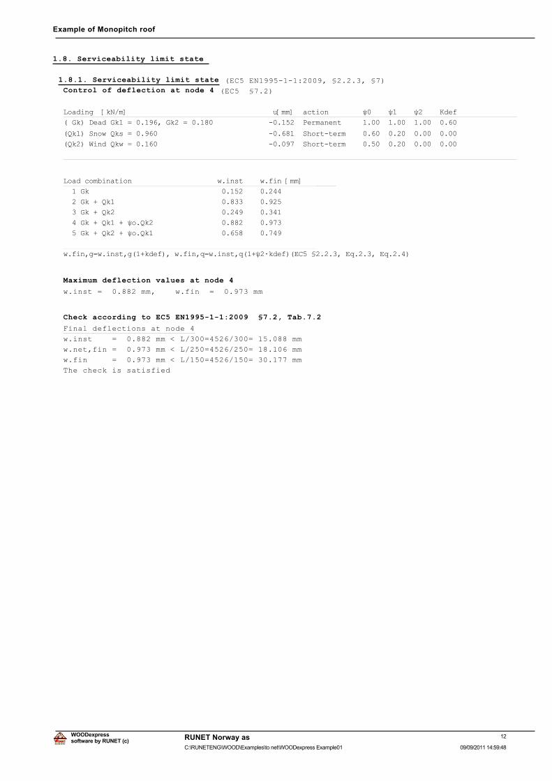
1.8. Serviceability limit state
1.8.1. Serviceability limit state (EC5 EN1995-1-1:2009, §2.2.3, §7)Control of deflection at node 4 (EC5 §7.2)
/RDGLQJ��>N1�P@����������������������������������X>PP@��DFWLRQ��������ȥ�����ȥ�����ȥ�����.GHI�
��*N��'HDG�*N�� ��������*N�� ���������������������������3HUPDQHQW����������������������������
�4N���6QRZ�4NV� ����������������������������������������6KRUW�WHUP���������������������������
�4N���:LQG�4NZ� ����������������������������������������6KRUW�WHUP���������������������������
���������������������������������������������������������������������������������������������
/RDG�FRPELQDWLRQ��������������������Z�LQVW����Z�ILQ�>PP@
����*N����������������������������������������������
����*N���4N�����������������������������������������
����*N���4N�����������������������������������������
����*N���4N����ȥR�4N��������������������������������
����*N���4N����ȥR�4N��������������������������������
����������������������������������������������������
Z�ILQ�J Z�LQVW�J���NGHI���Z�ILQ�T Z�LQVW�T���ȥ�ÂNGHI��(&����������(T������(T�����
Maximum deflection values at node 4
w.inst = 0.882 mm, w.fin = 0.973 mm
Check according to EC5 EN1995-1-1:2009 §7.2, Tab.7.2
Final deflections at node 4
w.inst = 0.882 mm < L/300=4526/300= 15.088 mm
w.net,fin = 0.973 mm < L/250=4526/250= 18.106 mm
w.fin = 0.973 mm < L/150=4526/150= 30.177 mm
The check is satisfied
12software by RUNET (c)
RUNET Norway as
09/09/2011 14:59:48C:\RUNETENG\WOOD\Examples\to net\WOODexpress Example01
WOODexpress
Example of Monopitch roof
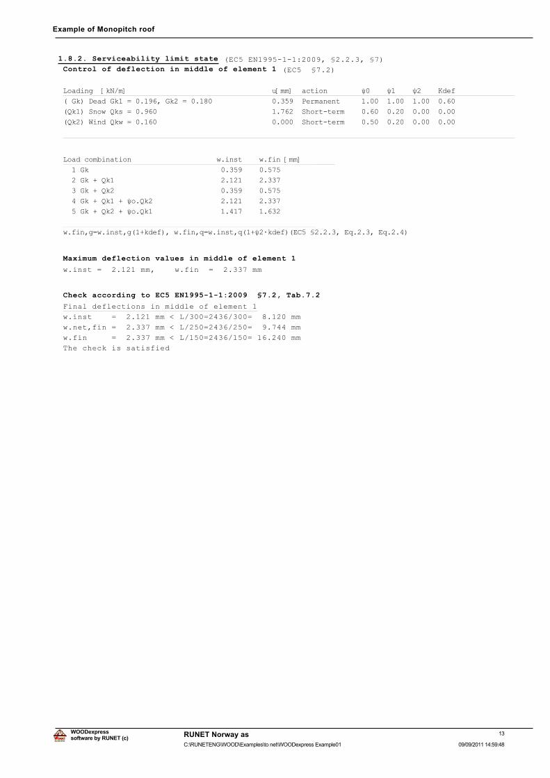
1.8.2. Serviceability limit state (EC5 EN1995-1-1:2009, §2.2.3, §7)Control of deflection in middle of element 1 (EC5 §7.2)
/RDGLQJ��>N1�P@����������������������������������X>PP@��DFWLRQ��������ȥ�����ȥ�����ȥ�����.GHI�
��*N��'HDG�*N�� ��������*N�� ���������������������������3HUPDQHQW����������������������������
�4N���6QRZ�4NV� ����������������������������������������6KRUW�WHUP���������������������������
�4N���:LQG�4NZ� ����������������������������������������6KRUW�WHUP���������������������������
���������������������������������������������������������������������������������������������
/RDG�FRPELQDWLRQ��������������������Z�LQVW����Z�ILQ�>PP@
����*N����������������������������������������������
����*N���4N�����������������������������������������
����*N���4N�����������������������������������������
����*N���4N����ȥR�4N��������������������������������
����*N���4N����ȥR�4N��������������������������������
����������������������������������������������������
Z�ILQ�J Z�LQVW�J���NGHI���Z�ILQ�T Z�LQVW�T���ȥ�ÂNGHI��(&����������(T������(T�����
Maximum deflection values in middle of element 1
w.inst = 2.121 mm, w.fin = 2.337 mm
Check according to EC5 EN1995-1-1:2009 §7.2, Tab.7.2
Final deflections in middle of element 1
w.inst = 2.121 mm < L/300=2436/300= 8.120 mm
w.net,fin = 2.337 mm < L/250=2436/250= 9.744 mm
w.fin = 2.337 mm < L/150=2436/150= 16.240 mm
The check is satisfied
13software by RUNET (c)
RUNET Norway as
09/09/2011 14:59:48C:\RUNETENG\WOOD\Examples\to net\WOODexpress Example01
WOODexpress
Example of Monopitch roof
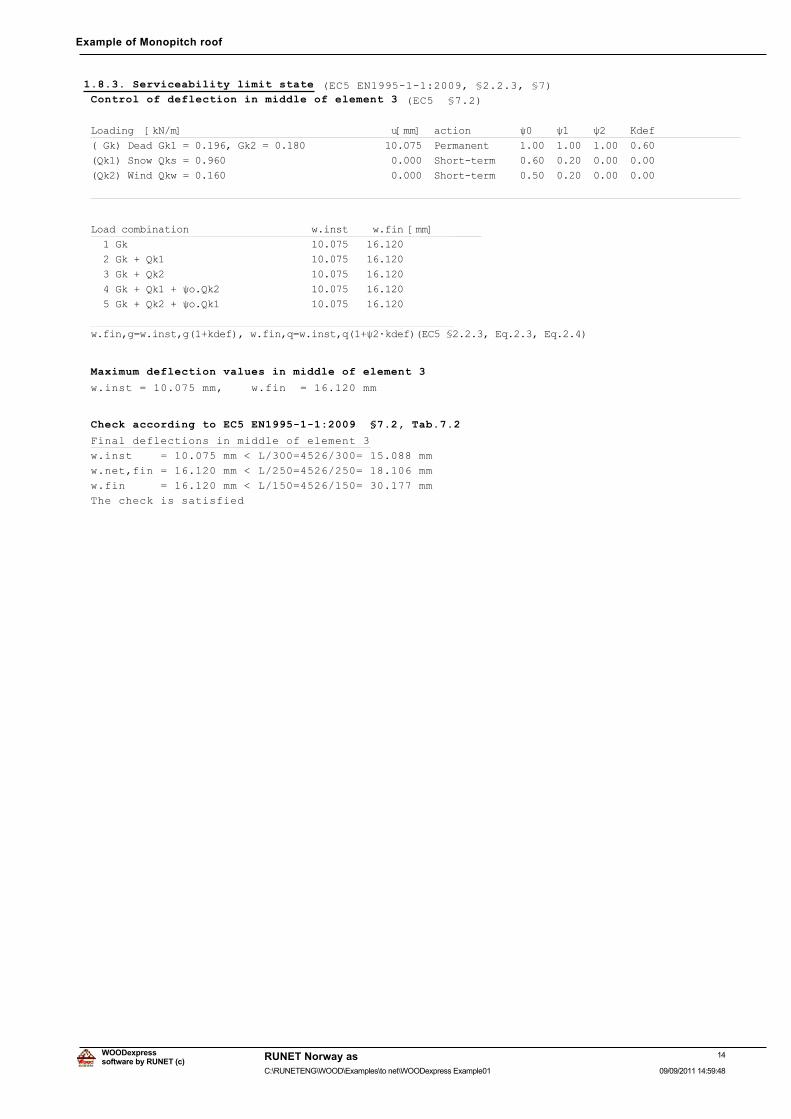
1.8.3. Serviceability limit state (EC5 EN1995-1-1:2009, §2.2.3, §7)Control of deflection in middle of element 3 (EC5 §7.2)
/RDGLQJ��>N1�P@����������������������������������X>PP@��DFWLRQ��������ȥ�����ȥ�����ȥ�����.GHI�
��*N��'HDG�*N�� ��������*N�� ���������������������������3HUPDQHQW����������������������������
�4N���6QRZ�4NV� ����������������������������������������6KRUW�WHUP���������������������������
�4N���:LQG�4NZ� ����������������������������������������6KRUW�WHUP���������������������������
���������������������������������������������������������������������������������������������
/RDG�FRPELQDWLRQ��������������������Z�LQVW����Z�ILQ�>PP@
����*N����������������������������������������������
����*N���4N�����������������������������������������
����*N���4N�����������������������������������������
����*N���4N����ȥR�4N��������������������������������
����*N���4N����ȥR�4N��������������������������������
����������������������������������������������������
Z�ILQ�J Z�LQVW�J���NGHI���Z�ILQ�T Z�LQVW�T���ȥ�ÂNGHI��(&����������(T������(T�����
Maximum deflection values in middle of element 3
w.inst = 10.075 mm, w.fin = 16.120 mm
Check according to EC5 EN1995-1-1:2009 §7.2, Tab.7.2
Final deflections in middle of element 3
w.inst = 10.075 mm < L/300=4526/300= 15.088 mm
w.net,fin = 16.120 mm < L/250=4526/250= 18.106 mm
w.fin = 16.120 mm < L/150=4526/150= 30.177 mm
The check is satisfied
14software by RUNET (c)
RUNET Norway as
09/09/2011 14:59:48C:\RUNETENG\WOOD\Examples\to net\WOODexpress Example01
WOODexpress
Example of Monopitch roof
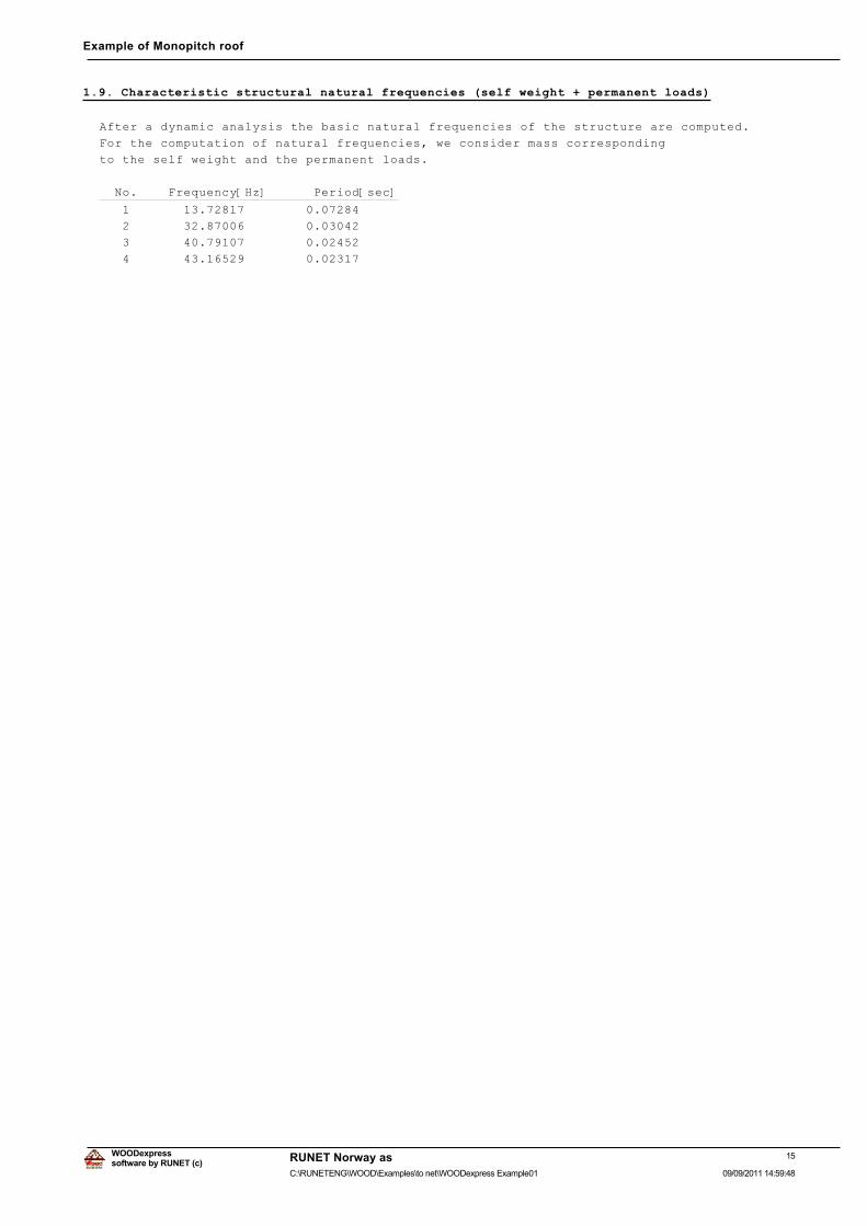
1.9. Characteristic structural natural frequencies (self weight + permanent loads)
After a dynamic analysis the basic natural frequencies of the structure are computed.
For the computation of natural frequencies, we consider mass corresponding
to the self weight and the permanent loads.
No. Frequency[Hz] Period[sec]
1 13.72817 0.07284
2 32.87006 0.03042
3 40.79107 0.02452
4 43.16529 0.02317
15software by RUNET (c)
RUNET Norway as
09/09/2011 14:59:48C:\RUNETENG\WOOD\Examples\to net\WOODexpress Example01
WOODexpress
Example of Monopitch roof
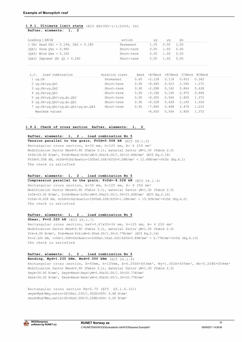
1.9.1. Ultimate limit state (EC5 EN1995-1-1:2009, §6)Rafter, elements: 1, 2
/RDGLQJ�>N1�P@������������������������������������DFWLRQ�����������ȖJ�����ȖT�����ȥR�
��*N��'HDG�*N�� ��������*N�� ��������������������3HUPDQHQW��������������������������
�4N���6QRZ�4NV� ���������������������������������6KRUW�WHUP�������������������������
�4N���:LQG�4NZ� ���������������������������������6KRUW�WHUP�������������������������
�4NL��,PSRVHG��+��4L� ���������������������������6KRUW�WHUP�������������������������
������������������������������������������������������������������������������������
�/�&����/RDG�FRPELQDWLRQ���������������GXUDWLRQ�FODVV�����NPRG���1�.PRG���1�.PRG��9�.PRG��0�.PRG
����ȖJ�*N��������������������������������3HUPDQHQW����������������������������������������������
����ȖJ�*N�ȖT�4N��������������������������6KRUW�WHUP���������������������������������������������
����ȖJ�*N�ȖT�4N��������������������������6KRUW�WHUP���������������������������������������������
����ȖJ�*N�ȖT�4NL�������������������������6KRUW�WHUP���������������������������������������������
����ȖJ�*N�ȖT�4N��ȖT�ȥR�4N����������������6KRUW�WHUP���������������������������������������������
����ȖJ�*N�ȖT�4N��ȖT�ȥR�4N����������������6KRUW�WHUP���������������������������������������������
����ȖJ�*N�ȖT�4NL�ȖT�ȥR�4N��ȖT�ȥR�4N������6KRUW�WHUP���������������������������������������������
����0D[LPXP�YDOXHV������������������������������������������������������������������������������
������������������������������������������������������������������������������������������������
1.9.2. Check of cross section Rafter, elements: 1, 2
Rafter, elements: 1, 2 , load combination No 5
Tension parallel to the grain, Ft0d=0.508 kN (EC5 §6.1.2)
Rectangular cross section, b=50 mm, h=125 mm, A= 6 250 mm²
0RGLILFDWLRQ�IDFWRU�.PRG ������7DEOH�������PDWHULDO�IDFWRU�Ȗ0 ������7DEOH�����
IW�N ������1�PPð��IW�G .PRGÂIW�N�Ȗ0 ����[���������� �����1�PPð��(&��(T������
)W�G ������N1��ıW�G )W�G�$QHWWR ����[���������� ����1�PPð��������1�PPð IW�G��(T�����
The check is satisfied
Rafter, elements: 1, 2 , load combination No 5
Compression parallel to the grain, Fc0d=-8.028 kN (EC5 §6.1.4)
Rectangular cross section, b=50 mm, h=125 mm, A= 6 250 mm²
0RGLILFDWLRQ�IDFWRU�.PRG ������7DEOH�������PDWHULDO�IDFWRU�Ȗ0 ������7DEOH�����
IF�N ������1�PPð��IF�G .PRGÂIF�N�Ȗ0 ����[���������� �����1�PPð��(&��(T������
)F�G �������N1��ıF�G )F�G�$QHWWR ����[���������� ����1�PPð��������1�PPð IF�G��(T�����
The check is satisfied
Rafter, elements: 1, 2 , load combination No 5
Shear, Fv=2.520 kN (EC5 §6.1.7)
Rectangular cross section, bef=0.67x50=34 mm, h=125 mm, A= 4 250 mm²
0RGLILFDWLRQ�IDFWRU�.PRG ������7DEOH�������PDWHULDO�IDFWRU�Ȗ0 ������7DEOH�����
IYN �����1�PPð��IYG .PRGÂIYN�Ȗ0 ����[��������� ����1�PPð��(&��(T������
)Y ������N1��IJY�G ����)Y�G�$QHWWR ����[����[���������� ����1�PPð�������1�PPð IY�G��(T������
The check is satisfied
Rafter, elements: 1, 2 , load combination No 5
Bending, Myd=1.235 kNm, Mzd=0.000 kNm (EC5 §6.1.6)
Rectangular cross section, b=50mm, h=125mm, A=6.250E+003mm², Wy=1.302E+005mm³, Wz=5.208E+004mm³
0RGLILFDWLRQ�IDFWRU�.PRG ������7DEOH�������PDWHULDO�IDFWRU�Ȗ0 ������7DEOH�����
IP\N ������1�PPð��IP\G .PRGÂIP\N�Ȗ0 ����[���������� �����1�PPð
IP]N ������1�PPð��IP]G .PRGÂIP]N�Ȗ0 ����[���������� �����1�PPð
Rectangular cross section Km=0.70 (EC5 §6.1.6.(2))
ıP\G 0\G�:P\�QHWWR �(���[�����������(���� ������1�PPð
ıP]G 0]G�:P]�QHWWR �(���[�����������(���� ������1�PPð
16software by RUNET (c)
RUNET Norway as
09/09/2011 14:59:48C:\RUNETENG\WOOD\Examples\to net\WOODexpress Example01
WOODexpress
Example of Monopitch roof
ıP\G�IP\G�.P�ıP]G�IP]G ����������� �����������(&��(T������
.P�ıP\G�IP\G�ıP]G�IP]G ����������� �����������(&��(T������
The check is satisfied
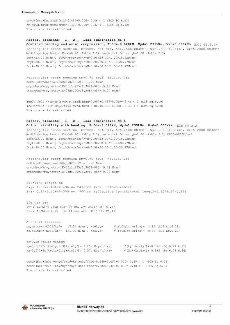
Rafter, elements: 1, 2 , load combination No 5
Combined bending and axial compression, Fc0d=-8.028kN, Myd=1.235kNm, Mzd=0.000kNm (EC5 §6.2.4)
Rectangular cross section, b=50mm, h=125mm, A=6.250E+003mm², Wy=1.302E+005mm³, Wz=5.208E+004mm³
0RGLILFDWLRQ�IDFWRU�.PRG ������7DEOH�������PDWHULDO�IDFWRU�Ȗ0 ������7DEOH�����
IF�N ������1�PPð��IF�G .PRGÂIF�N�Ȗ0 ����[���������� �����1�PPð
IP\N ������1�PPð��IP\G .PRGÂIP\N�Ȗ0 ����[���������� �����1�PPð
IP]N ������1�PPð��IP]G .PRGÂIP]N�Ȗ0 ����[���������� �����1�PPð
Rectangular cross section Km=0.70 (EC5 §6.1.6.(2))
ıF�G )F�G�$QHWWR ����[���������� ������1�PPð
ıP\G 0\G�:P\�QHWWR �(���[�����������(���� ������1�PPð
ıP]G 0]G�:P]�QHWWR �(���[�����������(���� ������1�PPð
�ıF�G�IF�G�ð�ıP\G�IP\G�.P�ıP]G�IP]G ����������������� �����������(&��(T������
�ıF�G�IF�G�ð�.P�ıP\G�IP\G�ıP]G�IP]G ����������������� �����������(&��(T������
The check is satisfied
Rafter, elements: 1, 2 , load combination No 5
Column stability with bending, Fc0d=-8.028kN, Myd=1.235kNm, Mzd=0.000kNm (EC5 §6.3.2)
Rectangular cross section, b=50mm, h=125mm, A=6.250E+003mm², Wy=1.302E+005mm³, Wz=5.208E+004mm³
0RGLILFDWLRQ�IDFWRU�.PRG ������7DEOH�������PDWHULDO�IDFWRU�Ȗ0 ������7DEOH������(��� ����1�PPð
IF�N ������1�PPð��IF�G .PRGÂIF�N�Ȗ0 ����[���������� �����1�PPð
IP\N ������1�PPð��IP\G .PRGÂIP\N�Ȗ0 ����[���������� �����1�PPð
IP]N ������1�PPð��IP]G .PRGÂIP]N�Ȗ0 ����[���������� �����1�PPð
Rectangular cross section Km=0.70 (EC5 §6.1.6.(2))
ıF�G )F�G�$QHWWR ����[���������� ������1�PPð
ıP\G 0\G�:P\�QHWWR �(���[�����������(���� ������1�PPð
ıP]G 0]G�:P]�QHWWR �(���[�����������(���� ������1�PPð
Buckling length Sk
Sky= 1.00x2.436=2.436 m= 2436 mm (most unfavourable)
Skz= 0.12x2.436=0.300 m= 300 mm (effective length/total length=0.30/2.44=0.12)
Slenderness
L\ Ö�,\�$� �����[���� ����PP��Ȝ\ ��������� ������L] Ö�,]�$� �����[���� ����PP��Ȝ] ��������� ������
Critical stresses
ıF�FULW\ ʌð(����Ȝ\ð ���������1�PPð��ȜUHO�\ Ö�IF�N�ıF�FULW\� ��������(&��(T������ıF�FULW] ʌð(����Ȝ]ð ���������1�PPð��ȜUHO�] Ö�IF�N�ıF�FULW]� ��������(&��(T������
ȕF ������VROLG�WLPEHU�
N\ ���>��ȕF�ȜUHO\������ȜUHO\ð@ �������.F\ ���N\� Ö�N\ð�ȜUHO\ð�� �������(T�����������N] ���>��ȕF�ȜUHO]������ȜUHO]ð@ �������.F] ���N]� Ö�N]ð�ȜUHO]ð�� �������(T�����������
ıF�G��.F\ÂIF�G��ıP\G�IP\G�.P�ıP]G�IP]G ����������������� �����������(&��(T������
ıF�G��.F]ÂIF�G��.P�ıP\G�IP\G�ıP]G�IP]G ����������������� �����������(&��(T������
The check is satisfied
17software by RUNET (c)
RUNET Norway as
09/09/2011 14:59:49C:\RUNETENG\WOOD\Examples\to net\WOODexpress Example01
WOODexpress
Example of Monopitch roof
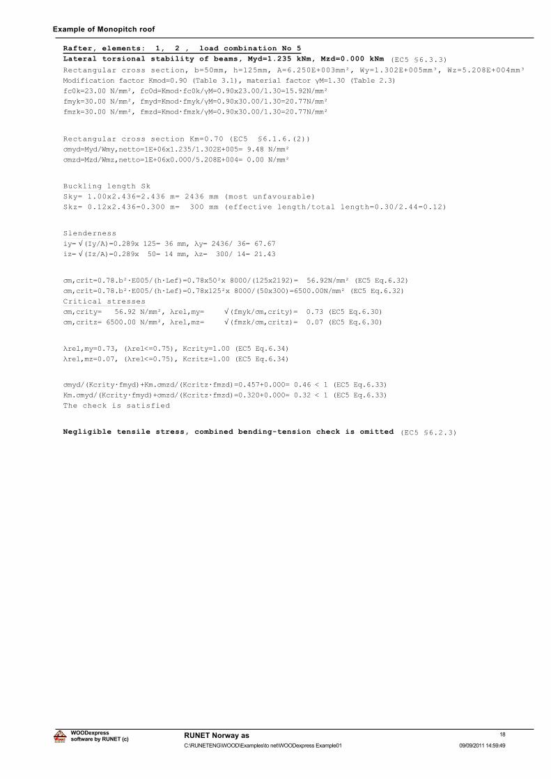
Rafter, elements: 1, 2 , load combination No 5
Lateral torsional stability of beams, Myd=1.235 kNm, Mzd=0.000 kNm (EC5 §6.3.3)
Rectangular cross section, b=50mm, h=125mm, A=6.250E+003mm², Wy=1.302E+005mm³, Wz=5.208E+004mm³
0RGLILFDWLRQ�IDFWRU�.PRG ������7DEOH�������PDWHULDO�IDFWRU�Ȗ0 ������7DEOH�����
IF�N ������1�PPð��IF�G .PRGÂIF�N�Ȗ0 ����[���������� �����1�PPð
IP\N ������1�PPð��IP\G .PRGÂIP\N�Ȗ0 ����[���������� �����1�PPð
IP]N ������1�PPð��IP]G .PRGÂIP]N�Ȗ0 ����[���������� �����1�PPð
Rectangular cross section Km=0.70 (EC5 §6.1.6.(2))
ıP\G 0\G�:P\�QHWWR �(���[�����������(���� ������1�PPð
ıP]G 0]G�:P]�QHWWR �(���[�����������(���� ������1�PPð
Buckling length Sk
Sky= 1.00x2.436=2.436 m= 2436 mm (most unfavourable)
Skz= 0.12x2.436=0.300 m= 300 mm (effective length/total length=0.30/2.44=0.12)
Slenderness
L\ Ö�,\�$� �����[���� ����PP��Ȝ\ ��������� ������L] Ö�,]�$� �����[���� ����PP��Ȝ] ��������� ������
ıP�FULW �����EðÂ(�����KÂ/HI� ����[��ð[����������[����� �������1�PPð��(&��(T������
ıP�FULW �����EðÂ(�����KÂ/HI� ����[���ð[���������[���� �������1�PPð��(&��(T������
Critical stresses
ıP�FULW\ ���������1�PPð��ȜUHO�P\ Ö�IP\N�ıP�FULW\� ��������(&��(T������ıP�FULW] ���������1�PPð��ȜUHO�P] Ö�IP]N�ıP�FULW]� ��������(&��(T������
ȜUHO�P\ �������ȜUHO� �������.FULW\ ������(&��(T������
ȜUHO�P] �������ȜUHO� �������.FULW] ������(&��(T������
ıP\G��.FULW\ÂIP\G��.P�ıP]G��.FULW]ÂIP]G� ����������� �����������(&��(T������
.P�ıP\G��.FULW\ÂIP\G��ıP]G��.FULW]ÂIP]G� ����������� �����������(&��(T������
The check is satisfied
Negligible tensile stress, combined bending-tension check is omitted (EC5 §6.2.3)
18software by RUNET (c)
RUNET Norway as
09/09/2011 14:59:49C:\RUNETENG\WOOD\Examples\to net\WOODexpress Example01
WOODexpress
Example of Monopitch roof
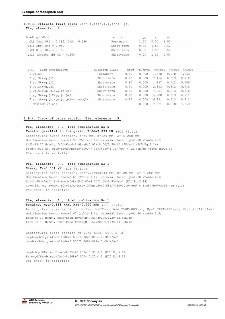
1.9.3. Ultimate limit state (EC5 EN1995-1-1:2009, §6)Tie, elements: 3
/RDGLQJ�>N1�P@������������������������������������DFWLRQ�����������ȖJ�����ȖT�����ȥR�
��*N��'HDG�*N�� ��������*N�� ��������������������3HUPDQHQW��������������������������
�4N���6QRZ�4NV� ���������������������������������6KRUW�WHUP�������������������������
�4N���:LQG�4NZ� ���������������������������������6KRUW�WHUP�������������������������
�4NL��,PSRVHG��+��4L� ���������������������������6KRUW�WHUP�������������������������
������������������������������������������������������������������������������������
�/�&����/RDG�FRPELQDWLRQ���������������GXUDWLRQ�FODVV�����NPRG���1�.PRG���1�.PRG��9�.PRG��0�.PRG
����ȖJ�*N��������������������������������3HUPDQHQW����������������������������������������������
����ȖJ�*N�ȖT�4N��������������������������6KRUW�WHUP���������������������������������������������
����ȖJ�*N�ȖT�4N��������������������������6KRUW�WHUP���������������������������������������������
����ȖJ�*N�ȖT�4NL�������������������������6KRUW�WHUP���������������������������������������������
����ȖJ�*N�ȖT�4N��ȖT�ȥR�4N����������������6KRUW�WHUP���������������������������������������������
����ȖJ�*N�ȖT�4N��ȖT�ȥR�4N����������������6KRUW�WHUP���������������������������������������������
����ȖJ�*N�ȖT�4NL�ȖT�ȥR�4N��ȖT�ȥR�4N������6KRUW�WHUP���������������������������������������������
����0D[LPXP�YDOXHV������������������������������������������������������������������������������
������������������������������������������������������������������������������������������������
1.9.4. Check of cross section Tie, elements: 3
Tie, elements: 3 , load combination No 5
Tension parallel to the grain, Ft0d=7.039 kN (EC5 §6.1.2)
Rectangular cross section, b=50 mm, h=125 mm, A= 6 250 mm²
0RGLILFDWLRQ�IDFWRU�.PRG ������7DEOH�������PDWHULDO�IDFWRU�Ȗ0 ������7DEOH�����
IW�N ������1�PPð��IW�G .PRGÂIW�N�Ȗ0 ����[���������� �����1�PPð��(&��(T������
)W�G ������N1��ıW�G )W�G�$QHWWR ����[���������� ����1�PPð��������1�PPð IW�G��(T�����
The check is satisfied
Tie, elements: 3 , load combination No 1
Shear, Fv=0.551 kN (EC5 §6.1.7)
Rectangular cross section, bef=0.67x50=34 mm, h=125 mm, A= 4 250 mm²
0RGLILFDWLRQ�IDFWRU�.PRG ������7DEOH�������PDWHULDO�IDFWRU�Ȗ0 ������7DEOH�����
IYN �����1�PPð��IYG .PRGÂIYN�Ȗ0 ����[��������� ����1�PPð��(&��(T������
)Y ������N1��IJY�G ����)Y�G�$QHWWR ����[����[���������� ����1�PPð�������1�PPð IY�G��(T������
The check is satisfied
Tie, elements: 3 , load combination No 1
Bending, Myd=0.638 kNm, Mzd=0.000 kNm (EC5 §6.1.6)
Rectangular cross section, b=50mm, h=125mm, A=6.250E+003mm², Wy=1.302E+005mm³, Wz=5.208E+004mm³
0RGLILFDWLRQ�IDFWRU�.PRG ������7DEOH�������PDWHULDO�IDFWRU�Ȗ0 ������7DEOH�����
IP\N ������1�PPð��IP\G .PRGÂIP\N�Ȗ0 ����[���������� �����1�PPð
IP]N ������1�PPð��IP]G .PRGÂIP]N�Ȗ0 ����[���������� �����1�PPð
Rectangular cross section Km=0.70 (EC5 §6.1.6.(2))
ıP\G 0\G�:P\�QHWWR �(���[�����������(���� ������1�PPð
ıP]G 0]G�:P]�QHWWR �(���[�����������(���� ������1�PPð
ıP\G�IP\G�.P�ıP]G�IP]G ����������� �����������(&��(T������
.P�ıP\G�IP\G�ıP]G�IP]G ����������� �����������(&��(T������
The check is satisfied
19software by RUNET (c)
RUNET Norway as
09/09/2011 14:59:49C:\RUNETENG\WOOD\Examples\to net\WOODexpress Example01
WOODexpress
Example of Monopitch roof
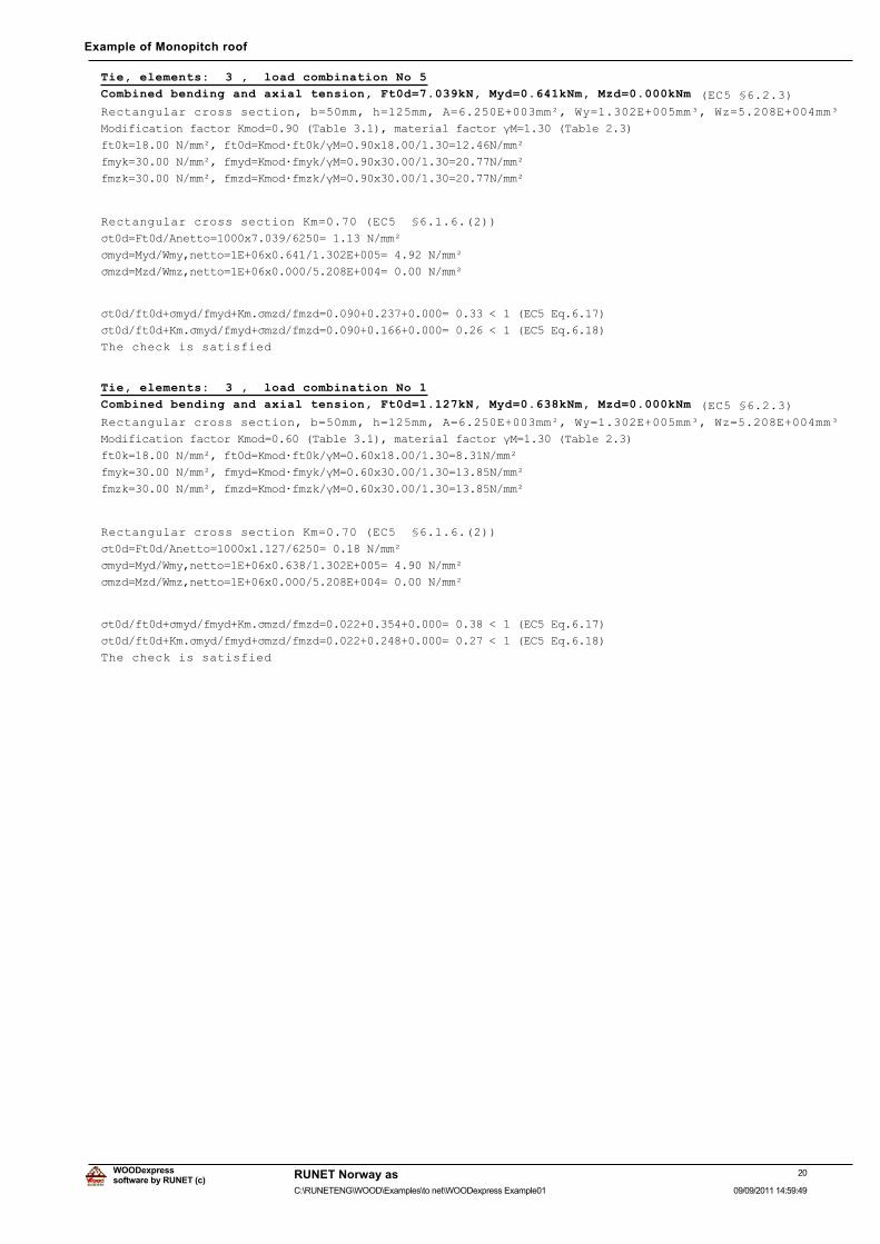
Tie, elements: 3 , load combination No 5
Combined bending and axial tension, Ft0d=7.039kN, Myd=0.641kNm, Mzd=0.000kNm (EC5 §6.2.3)
Rectangular cross section, b=50mm, h=125mm, A=6.250E+003mm², Wy=1.302E+005mm³, Wz=5.208E+004mm³
0RGLILFDWLRQ�IDFWRU�.PRG ������7DEOH�������PDWHULDO�IDFWRU�Ȗ0 ������7DEOH�����
IW�N ������1�PPð��IW�G .PRGÂIW�N�Ȗ0 ����[���������� �����1�PPð
IP\N ������1�PPð��IP\G .PRGÂIP\N�Ȗ0 ����[���������� �����1�PPð
IP]N ������1�PPð��IP]G .PRGÂIP]N�Ȗ0 ����[���������� �����1�PPð
Rectangular cross section Km=0.70 (EC5 §6.1.6.(2))
ıW�G )W�G�$QHWWR ����[���������� ������1�PPð
ıP\G 0\G�:P\�QHWWR �(���[�����������(���� ������1�PPð
ıP]G 0]G�:P]�QHWWR �(���[�����������(���� ������1�PPð
ıW�G�IW�G�ıP\G�IP\G�.P�ıP]G�IP]G ����������������� �����������(&��(T������
ıW�G�IW�G�.P�ıP\G�IP\G�ıP]G�IP]G ����������������� �����������(&��(T������
The check is satisfied
Tie, elements: 3 , load combination No 1
Combined bending and axial tension, Ft0d=1.127kN, Myd=0.638kNm, Mzd=0.000kNm (EC5 §6.2.3)
Rectangular cross section, b=50mm, h=125mm, A=6.250E+003mm², Wy=1.302E+005mm³, Wz=5.208E+004mm³
0RGLILFDWLRQ�IDFWRU�.PRG ������7DEOH�������PDWHULDO�IDFWRU�Ȗ0 ������7DEOH�����
IW�N ������1�PPð��IW�G .PRGÂIW�N�Ȗ0 ����[���������� ����1�PPð
IP\N ������1�PPð��IP\G .PRGÂIP\N�Ȗ0 ����[���������� �����1�PPð
IP]N ������1�PPð��IP]G .PRGÂIP]N�Ȗ0 ����[���������� �����1�PPð
Rectangular cross section Km=0.70 (EC5 §6.1.6.(2))
ıW�G )W�G�$QHWWR ����[���������� ������1�PPð
ıP\G 0\G�:P\�QHWWR �(���[�����������(���� ������1�PPð
ıP]G 0]G�:P]�QHWWR �(���[�����������(���� ������1�PPð
ıW�G�IW�G�ıP\G�IP\G�.P�ıP]G�IP]G ����������������� �����������(&��(T������
ıW�G�IW�G�.P�ıP\G�IP\G�ıP]G�IP]G ����������������� �����������(&��(T������
The check is satisfied
20software by RUNET (c)
RUNET Norway as
09/09/2011 14:59:49C:\RUNETENG\WOOD\Examples\to net\WOODexpress Example01
WOODexpress
Example of Monopitch roof
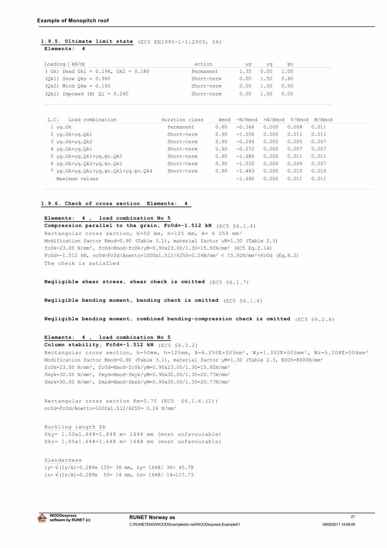
1.9.5. Ultimate limit state (EC5 EN1995-1-1:2009, §6)Elements: 4
/RDGLQJ�>N1�P@������������������������������������DFWLRQ�����������ȖJ�����ȖT�����ȥR�
��*N��'HDG�*N�� ��������*N�� ��������������������3HUPDQHQW��������������������������
�4N���6QRZ�4NV� ���������������������������������6KRUW�WHUP�������������������������
�4N���:LQG�4NZ� ���������������������������������6KRUW�WHUP�������������������������
�4NL��,PSRVHG��+��4L� ���������������������������6KRUW�WHUP�������������������������
������������������������������������������������������������������������������������
�/�&����/RDG�FRPELQDWLRQ���������������GXUDWLRQ�FODVV�����NPRG���1�.PRG���1�.PRG��9�.PRG��0�.PRG
����ȖJ�*N��������������������������������3HUPDQHQW����������������������������������������������
����ȖJ�*N�ȖT�4N��������������������������6KRUW�WHUP���������������������������������������������
����ȖJ�*N�ȖT�4N��������������������������6KRUW�WHUP���������������������������������������������
����ȖJ�*N�ȖT�4NL�������������������������6KRUW�WHUP���������������������������������������������
����ȖJ�*N�ȖT�4N��ȖT�ȥR�4N����������������6KRUW�WHUP���������������������������������������������
����ȖJ�*N�ȖT�4N��ȖT�ȥR�4N����������������6KRUW�WHUP���������������������������������������������
����ȖJ�*N�ȖT�4NL�ȖT�ȥR�4N��ȖT�ȥR�4N������6KRUW�WHUP���������������������������������������������
����0D[LPXP�YDOXHV������������������������������������������������������������������������������
������������������������������������������������������������������������������������������������
1.9.6. Check of cross section Elements: 4
Elements: 4 , load combination No 5
Compression parallel to the grain, Fc0d=-1.512 kN (EC5 §6.1.4)
Rectangular cross section, b=50 mm, h=125 mm, A= 6 250 mm²
0RGLILFDWLRQ�IDFWRU�.PRG ������7DEOH�������PDWHULDO�IDFWRU�Ȗ0 ������7DEOH�����
IF�N ������1�PPð��IF�G .PRGÂIF�N�Ȗ0 ����[���������� �����1�PPð��(&��(T������
)F�G �������N1��ıF�G )F�G�$QHWWR ����[���������� ����1�PPð��������1�PPð IF�G��(T�����
The check is satisfied
Negligible shear stress, shear check is omitted (EC5 §6.1.7)
Negligible bending moment, bending check is omitted (EC5 §6.1.6)
Negligible bending moment, combined bending-compression check is omitted (EC5 §6.2.4)
Elements: 4 , load combination No 5
Column stability, Fc0d=-1.512 kN (EC5 §6.3.2)
Rectangular cross section, b=50mm, h=125mm, A=6.250E+003mm², Wy=1.302E+005mm³, Wz=5.208E+004mm³
0RGLILFDWLRQ�IDFWRU�.PRG ������7DEOH�������PDWHULDO�IDFWRU�Ȗ0 ������7DEOH������(��� ����1�PPð
IF�N ������1�PPð��IF�G .PRGÂIF�N�Ȗ0 ����[���������� �����1�PPð
IP\N ������1�PPð��IP\G .PRGÂIP\N�Ȗ0 ����[���������� �����1�PPð
IP]N ������1�PPð��IP]G .PRGÂIP]N�Ȗ0 ����[���������� �����1�PPð
Rectangular cross section Km=0.70 (EC5 §6.1.6.(2))
ıF�G )F�G�$QHWWR ����[���������� ������1�PPð
Buckling length Sk
Sky= 1.00x1.648=1.648 m= 1648 mm (most unfavourable)
Skz= 1.00x1.648=1.648 m= 1648 mm (most unfavourable)
Slenderness
L\ Ö�,\�$� �����[���� ����PP��Ȝ\ ��������� ������L] Ö�,]�$� �����[���� ����PP��Ȝ] ��������� ������
21software by RUNET (c)
RUNET Norway as
09/09/2011 14:59:49C:\RUNETENG\WOOD\Examples\to net\WOODexpress Example01
WOODexpress
Example of Monopitch roof
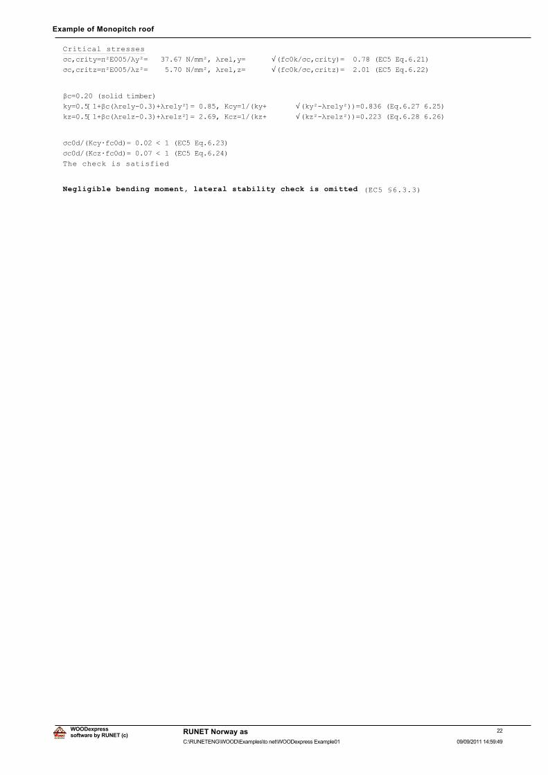
Critical stresses
ıF�FULW\ ʌð(����Ȝ\ð ���������1�PPð��ȜUHO�\ Ö�IF�N�ıF�FULW\� ��������(&��(T������ıF�FULW] ʌð(����Ȝ]ð ���������1�PPð��ȜUHO�] Ö�IF�N�ıF�FULW]� ��������(&��(T������
ȕF ������VROLG�WLPEHU�
N\ ���>��ȕF�ȜUHO\������ȜUHO\ð@ �������.F\ ���N\� Ö�N\ð�ȜUHO\ð�� �������(T�����������N] ���>��ȕF�ȜUHO]������ȜUHO]ð@ �������.F] ���N]� Ö�N]ð�ȜUHO]ð�� �������(T�����������
ıF�G��.F\ÂIF�G� �����������(&��(T������
ıF�G��.F]ÂIF�G� �����������(&��(T������
The check is satisfied
Negligible bending moment, lateral stability check is omitted (EC5 §6.3.3)
22software by RUNET (c)
RUNET Norway as
09/09/2011 14:59:49C:\RUNETENG\WOOD\Examples\to net\WOODexpress Example01
WOODexpress
Example of Monopitch roof
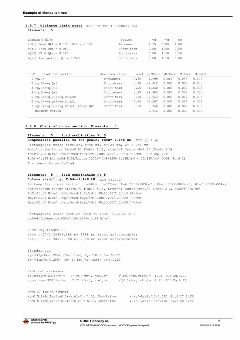
1.9.7. Ultimate limit state (EC5 EN1995-1-1:2009, §6)Elements: 5
/RDGLQJ�>N1�P@������������������������������������DFWLRQ�����������ȖJ�����ȖT�����ȥR�
��*N��'HDG�*N�� ��������*N�� ��������������������3HUPDQHQW��������������������������
�4N���6QRZ�4NV� ���������������������������������6KRUW�WHUP�������������������������
�4N���:LQG�4NZ� ���������������������������������6KRUW�WHUP�������������������������
�4NL��,PSRVHG��+��4L� ���������������������������6KRUW�WHUP�������������������������
������������������������������������������������������������������������������������
�/�&����/RDG�FRPELQDWLRQ���������������GXUDWLRQ�FODVV�����NPRG���1�.PRG���1�.PRG��9�.PRG��0�.PRG
����ȖJ�*N��������������������������������3HUPDQHQW����������������������������������������������
����ȖJ�*N�ȖT�4N��������������������������6KRUW�WHUP���������������������������������������������
����ȖJ�*N�ȖT�4N��������������������������6KRUW�WHUP���������������������������������������������
����ȖJ�*N�ȖT�4NL�������������������������6KRUW�WHUP���������������������������������������������
����ȖJ�*N�ȖT�4N��ȖT�ȥR�4N����������������6KRUW�WHUP���������������������������������������������
����ȖJ�*N�ȖT�4N��ȖT�ȥR�4N����������������6KRUW�WHUP���������������������������������������������
����ȖJ�*N�ȖT�4NL�ȖT�ȥR�4N��ȖT�ȥR�4N������6KRUW�WHUP���������������������������������������������
����0D[LPXP�YDOXHV������������������������������������������������������������������������������
������������������������������������������������������������������������������������������������
1.9.8. Check of cross section Elements: 5
Elements: 5 , load combination No 5
Compression parallel to the grain, Fc0d=-7.148 kN (EC5 §6.1.4)
Rectangular cross section, b=50 mm, h=125 mm, A= 6 250 mm²
0RGLILFDWLRQ�IDFWRU�.PRG ������7DEOH�������PDWHULDO�IDFWRU�Ȗ0 ������7DEOH�����
IF�N ������1�PPð��IF�G .PRGÂIF�N�Ȗ0 ����[���������� �����1�PPð��(&��(T������
)F�G �������N1��ıF�G )F�G�$QHWWR ����[���������� ����1�PPð��������1�PPð IF�G��(T�����
The check is satisfied
Elements: 5 , load combination No 5
Column stability, Fc0d=-7.148 kN (EC5 §6.3.2)
Rectangular cross section, b=50mm, h=125mm, A=6.250E+003mm², Wy=1.302E+005mm³, Wz=5.208E+004mm³
0RGLILFDWLRQ�IDFWRU�.PRG ������7DEOH�������PDWHULDO�IDFWRU�Ȗ0 ������7DEOH������(��� ����1�PPð
IF�N ������1�PPð��IF�G .PRGÂIF�N�Ȗ0 ����[���������� �����1�PPð
IP\N ������1�PPð��IP\G .PRGÂIP\N�Ȗ0 ����[���������� �����1�PPð
IP]N ������1�PPð��IP]G .PRGÂIP]N�Ȗ0 ����[���������� �����1�PPð
Rectangular cross section Km=0.70 (EC5 §6.1.6.(2))
ıF�G )F�G�$QHWWR ����[���������� ������1�PPð
Buckling length Sk
Sky= 1.00x2.388=2.388 m= 2388 mm (most unfavourable)
Skz= 1.00x2.388=2.388 m= 2388 mm (most unfavourable)
Slenderness
L\ Ö�,\�$� �����[���� ����PP��Ȝ\ ��������� ������L] Ö�,]�$� �����[���� ����PP��Ȝ] ��������� ������
Critical stresses
ıF�FULW\ ʌð(����Ȝ\ð ���������1�PPð��ȜUHO�\ Ö�IF�N�ıF�FULW\� ��������(&��(T������ıF�FULW] ʌð(����Ȝ]ð ���������1�PPð��ȜUHO�] Ö�IF�N�ıF�FULW]� ��������(&��(T������
ȕF ������VROLG�WLPEHU�
N\ ���>��ȕF�ȜUHO\������ȜUHO\ð@ �������.F\ ���N\� Ö�N\ð�ȜUHO\ð�� �������(T�����������N] ���>��ȕF�ȜUHO]������ȜUHO]ð@ �������.F] ���N]� Ö�N]ð�ȜUHO]ð�� �������(T�����������
23software by RUNET (c)
RUNET Norway as
09/09/2011 14:59:49C:\RUNETENG\WOOD\Examples\to net\WOODexpress Example01
WOODexpress
Example of Monopitch roof
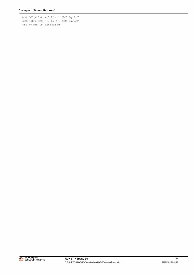
ıF�G��.F\ÂIF�G� �����������(&��(T������
ıF�G��.F]ÂIF�G� �����������(&��(T������
The check is satisfied
24software by RUNET (c)
RUNET Norway as
09/09/2011 14:59:49C:\RUNETENG\WOOD\Examples\to net\WOODexpress Example01
WOODexpress
Example of Monopitch roof
1.10. Truss connections
1.10.1. Lateral Load-carrying capacity of connections (EC5 EN1995-1-1:2009, §8)
Connection nails and connection plates
Selected nails 4.0/35 mm (d=4.0mm, L=35mm). Metal plates , t=2.0 mm.
Yield strength for plate steel fy=240 N/mm². Net plate area (minus holes) Anet=(0.75)·b·t
Cross section properties
Thickness of timber d=50.0 mm, thickness of steel plate t=2.0 mmNail properties (EC5 §8.3.1)
Smooth nails, round cross section, no pre-drilling
Nail diameter d=4.0 mm, nail length l=35 mm.Distance between nails (EC5 Table 8.2)
as most unfavourable is chosen a1=14d=14x4.0=56 mm, a2=5d=20 mm
Characteristic value for yield moment (EC5 §8.3.1.1)
Myrk=0.30fud^2.6=0.30x600x4.0^2.6=6617 Nmm (fu=600N/mm²) (EN1995-1-1 Eq.8.14)
Characteristic value of embedment strength (EC5 §8.3.1.1)
IKN �����ȡN�GA��� �����1�PPð���ȡN ���NJ�Pñ��G ���PP���(1���������(T������
Permanent action
Capacity of laterally loaded nails -Single shear connection (EC5 §8.2.3)
t2=33.0 mm (nail depth), thickness of steel plate t=2.0<=0.5d=0.5x4.0=2.0 mm
Fvrk=the minimum of the values (EC5 EN1995-1-1:2009 Eq.8.9(a), 8.9(b))
0.40fhk·t2·d=1.086 kN
1.15Ö[2Myrk·fhk·d]=1.200 kN/DWHUDO�ORDG�FDUU\LQJ�FDSDFLW\�RI�QDLO�5G .PRGÂ)YUN�Ȗ0 ����[���������� ������N1
Medium-term action
Capacity of laterally loaded nails -Single shear connection (EC5 §8.2.3)
t2=33.0 mm (nail depth), thickness of steel plate t=2.0<=0.5d=0.5x4.0=2.0 mm
Fvrk=the minimum of the values (EC5 EN1995-1-1:2009 Eq.8.9(a), 8.9(b))
0.40fhk·t2·d=1.086 kN
1.15Ö[2Myrk·fhk·d]=1.200 kN/DWHUDO�ORDG�FDUU\LQJ�FDSDFLW\�RI�QDLO�5G .PRGÂ)YUN�Ȗ0 ����[���������� ������N1
Short-term action
Capacity of laterally loaded nails -Single shear connection (EC5 §8.2.3)
t2=33.0 mm (nail depth), thickness of steel plate t=2.0<=0.5d=0.5x4.0=2.0 mm
Fvrk=the minimum of the values (EC5 EN1995-1-1:2009 Eq.8.9(a), 8.9(b))
0.40fhk·t2·d=1.086 kN
1.15Ö[2Myrk·fhk·d]=1.200 kN/DWHUDO�ORDG�FDUU\LQJ�FDSDFLW\�RI�QDLO�5G .PRGÂ)YUN�Ȗ0 ����[���������� ������N1
Assumptions for the design of nailed connections
The design of connections is based on plastic analysis. The forces at the nails
are all reaching the same limit value. The metal plate capacity is based on
plastic section modulus. The compressive design force is reduced to 0.50xFd
25software by RUNET (c)
RUNET Norway as
09/09/2011 14:59:49C:\RUNETENG\WOOD\Examples\to net\WOODexpress Example01
WOODexpress
Example of Monopitch roof
1.10.2. Ultimate limit state
Design of nailed connection at node : 2 (EC5 EN1995-1-1:2009, §8.3)
Connection with double (2) metal plates on the two faces of the truss.
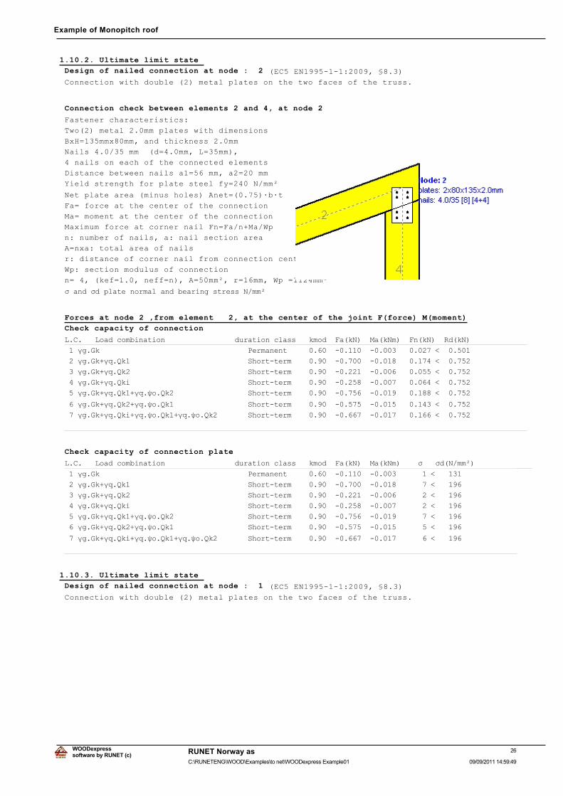
Connection check between elements 2 and 4, at node 2
Fastener characteristics:
Two(2) metal 2.0mm plates with dimensions
BxH=135mmx80mm, and thickness 2.0mm
Nails 4.0/35 mm (d=4.0mm, L=35mm),
4 nails on each of the connected elements
Distance between nails a1=56 mm, a2=20 mm
Yield strength for plate steel fy=240 N/mm²
Net plate area (minus holes) Anet=(0.75)·b·t
Fa= force at the center of the connection
Ma= moment at the center of the connection
Maximum force at corner nail Fn=Fa/n+Ma/Wp
n: number of nails, a: nail section area
A=nxa: total area of nails
r: distance of corner nail from connection center
Wp: section modulus of connection
n= 4, (kef=1.0, neff=n), A=50mm², r=16mm, Wp =1124mm³
ı�DQG�ıG�SODWH�QRUPDO�DQG�EHDULQJ�VWUHVV�1�PPð
Forces at node 2 ,from element 2, at the center of the joint F(force) M(moment)
Check capacity of connection
/�&����/RDG�FRPELQDWLRQ����������������GXUDWLRQ�FODVV���NPRG��)D�N1���0D�N1P���)Q�N1���5G�N1�
���ȖJ�*N����������������������������������3HUPDQHQW������������������������������������������
���ȖJ�*N�ȖT�4N����������������������������6KRUW�WHUP�����������������������������������������
���ȖJ�*N�ȖT�4N����������������������������6KRUW�WHUP�����������������������������������������
���ȖJ�*N�ȖT�4NL���������������������������6KRUW�WHUP�����������������������������������������
���ȖJ�*N�ȖT�4N��ȖT�ȥR�4N������������������6KRUW�WHUP�����������������������������������������
���ȖJ�*N�ȖT�4N��ȖT�ȥR�4N������������������6KRUW�WHUP�����������������������������������������
���ȖJ�*N�ȖT�4NL�ȖT�ȥR�4N��ȖT�ȥR�4N��������6KRUW�WHUP�����������������������������������������
���������������������������������������������������������������������������������������������
Check capacity of connection plate
/�&����/RDG�FRPELQDWLRQ����������������GXUDWLRQ�FODVV���NPRG��)D�N1���0D�N1P�����ı���ıG�1�PPð�
���ȖJ�*N����������������������������������3HUPDQHQW����������������������������������������
���ȖJ�*N�ȖT�4N����������������������������6KRUW�WHUP���������������������������������������
���ȖJ�*N�ȖT�4N����������������������������6KRUW�WHUP���������������������������������������
���ȖJ�*N�ȖT�4NL���������������������������6KRUW�WHUP���������������������������������������
���ȖJ�*N�ȖT�4N��ȖT�ȥR�4N������������������6KRUW�WHUP���������������������������������������
���ȖJ�*N�ȖT�4N��ȖT�ȥR�4N������������������6KRUW�WHUP���������������������������������������
���ȖJ�*N�ȖT�4NL�ȖT�ȥR�4N��ȖT�ȥR�4N��������6KRUW�WHUP���������������������������������������
�������������������������������������������������������������������������������������������
1.10.3. Ultimate limit state
Design of nailed connection at node : 1 (EC5 EN1995-1-1:2009, §8.3)
Connection with double (2) metal plates on the two faces of the truss.
26software by RUNET (c)
RUNET Norway as
09/09/2011 14:59:49C:\RUNETENG\WOOD\Examples\to net\WOODexpress Example01
WOODexpress
Example of Monopitch roof
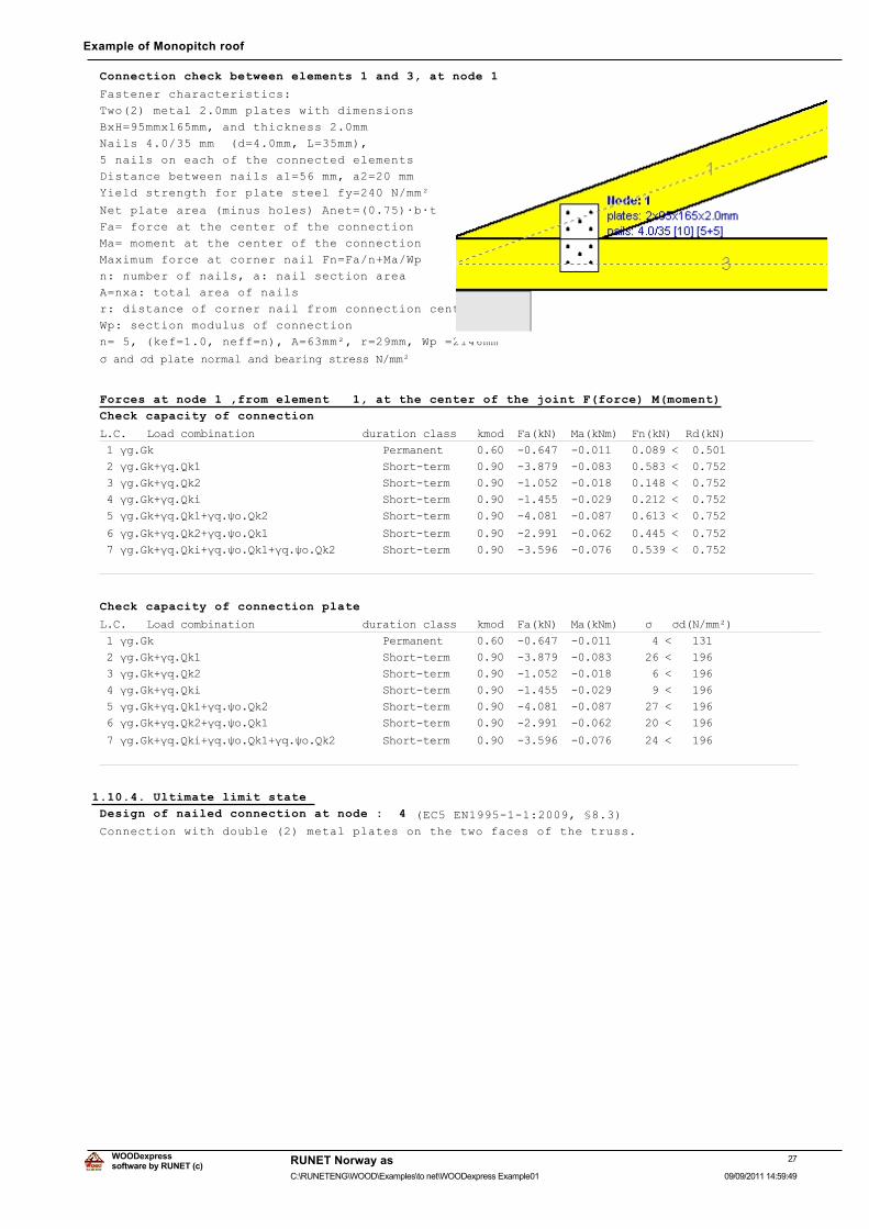
Connection check between elements 1 and 3, at node 1
Fastener characteristics:
Two(2) metal 2.0mm plates with dimensions
BxH=95mmx165mm, and thickness 2.0mm
Nails 4.0/35 mm (d=4.0mm, L=35mm),
5 nails on each of the connected elements
Distance between nails a1=56 mm, a2=20 mm
Yield strength for plate steel fy=240 N/mm²
Net plate area (minus holes) Anet=(0.75)·b·t
Fa= force at the center of the connection
Ma= moment at the center of the connection
Maximum force at corner nail Fn=Fa/n+Ma/Wp
n: number of nails, a: nail section area
A=nxa: total area of nails
r: distance of corner nail from connection center
Wp: section modulus of connection
n= 5, (kef=1.0, neff=n), A=63mm², r=29mm, Wp =2146mm³
ı�DQG�ıG�SODWH�QRUPDO�DQG�EHDULQJ�VWUHVV�1�PPð
Forces at node 1 ,from element 1, at the center of the joint F(force) M(moment)
Check capacity of connection
/�&����/RDG�FRPELQDWLRQ����������������GXUDWLRQ�FODVV���NPRG��)D�N1���0D�N1P���)Q�N1���5G�N1�
���ȖJ�*N����������������������������������3HUPDQHQW������������������������������������������
���ȖJ�*N�ȖT�4N����������������������������6KRUW�WHUP�����������������������������������������
���ȖJ�*N�ȖT�4N����������������������������6KRUW�WHUP�����������������������������������������
���ȖJ�*N�ȖT�4NL���������������������������6KRUW�WHUP�����������������������������������������
���ȖJ�*N�ȖT�4N��ȖT�ȥR�4N������������������6KRUW�WHUP�����������������������������������������
���ȖJ�*N�ȖT�4N��ȖT�ȥR�4N������������������6KRUW�WHUP�����������������������������������������
���ȖJ�*N�ȖT�4NL�ȖT�ȥR�4N��ȖT�ȥR�4N��������6KRUW�WHUP�����������������������������������������
���������������������������������������������������������������������������������������������
Check capacity of connection plate
/�&����/RDG�FRPELQDWLRQ����������������GXUDWLRQ�FODVV���NPRG��)D�N1���0D�N1P�����ı���ıG�1�PPð�
���ȖJ�*N����������������������������������3HUPDQHQW����������������������������������������
���ȖJ�*N�ȖT�4N����������������������������6KRUW�WHUP���������������������������������������
���ȖJ�*N�ȖT�4N����������������������������6KRUW�WHUP���������������������������������������
���ȖJ�*N�ȖT�4NL���������������������������6KRUW�WHUP���������������������������������������
���ȖJ�*N�ȖT�4N��ȖT�ȥR�4N������������������6KRUW�WHUP���������������������������������������
���ȖJ�*N�ȖT�4N��ȖT�ȥR�4N������������������6KRUW�WHUP���������������������������������������
���ȖJ�*N�ȖT�4NL�ȖT�ȥR�4N��ȖT�ȥR�4N��������6KRUW�WHUP���������������������������������������
�������������������������������������������������������������������������������������������
1.10.4. Ultimate limit state
Design of nailed connection at node : 4 (EC5 EN1995-1-1:2009, §8.3)
Connection with double (2) metal plates on the two faces of the truss.
27software by RUNET (c)
RUNET Norway as
09/09/2011 14:59:49C:\RUNETENG\WOOD\Examples\to net\WOODexpress Example01
WOODexpress
Example of Monopitch roof
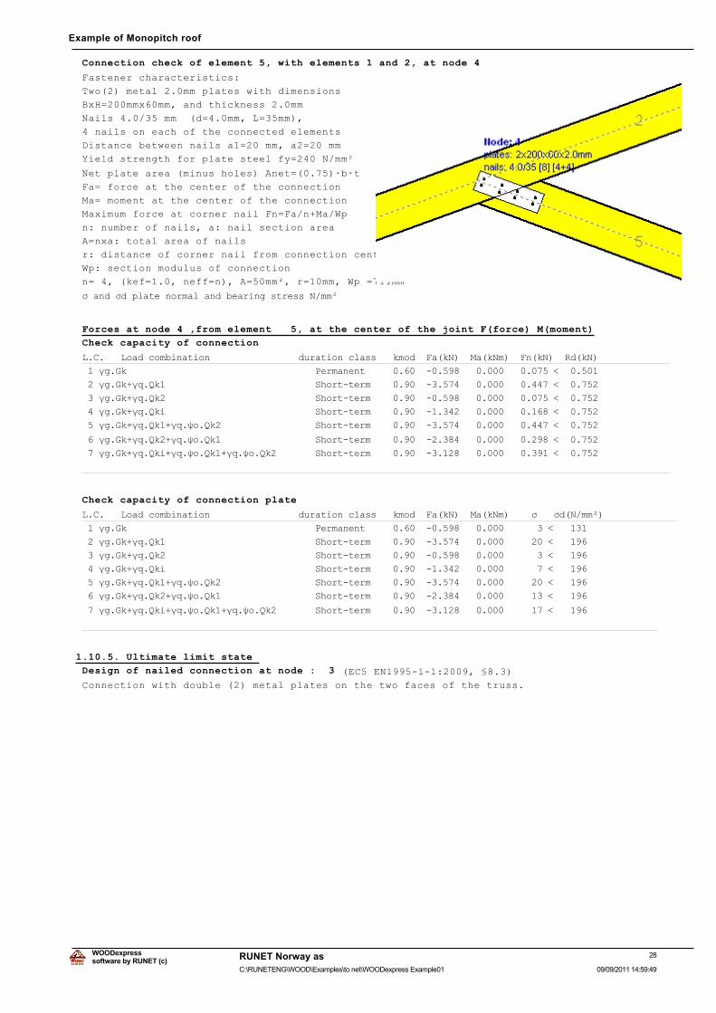
Connection check of element 5, with elements 1 and 2, at node 4
Fastener characteristics:
Two(2) metal 2.0mm plates with dimensions
BxH=200mmx60mm, and thickness 2.0mm
Nails 4.0/35 mm (d=4.0mm, L=35mm),
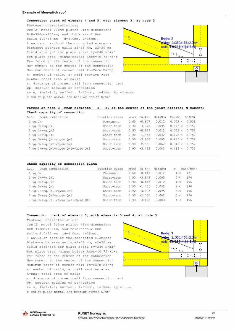
4 nails on each of the connected elements
Distance between nails a1=20 mm, a2=20 mm
Yield strength for plate steel fy=240 N/mm²
Net plate area (minus holes) Anet=(0.75)·b·t
Fa= force at the center of the connection
Ma= moment at the center of the connection
Maximum force at corner nail Fn=Fa/n+Ma/Wp
n: number of nails, a: nail section area
A=nxa: total area of nails
r: distance of corner nail from connection center
Wp: section modulus of connection
n= 4, (kef=1.0, neff=n), A=50mm², r=10mm, Wp =711mm³
ı�DQG�ıG�SODWH�QRUPDO�DQG�EHDULQJ�VWUHVV�1�PPð
Forces at node 4 ,from element 5, at the center of the joint F(force) M(moment)
Check capacity of connection
/�&����/RDG�FRPELQDWLRQ����������������GXUDWLRQ�FODVV���NPRG��)D�N1���0D�N1P���)Q�N1���5G�N1�
���ȖJ�*N����������������������������������3HUPDQHQW������������������������������������������
���ȖJ�*N�ȖT�4N����������������������������6KRUW�WHUP�����������������������������������������
���ȖJ�*N�ȖT�4N����������������������������6KRUW�WHUP�����������������������������������������
���ȖJ�*N�ȖT�4NL���������������������������6KRUW�WHUP�����������������������������������������
���ȖJ�*N�ȖT�4N��ȖT�ȥR�4N������������������6KRUW�WHUP�����������������������������������������
���ȖJ�*N�ȖT�4N��ȖT�ȥR�4N������������������6KRUW�WHUP�����������������������������������������
���ȖJ�*N�ȖT�4NL�ȖT�ȥR�4N��ȖT�ȥR�4N��������6KRUW�WHUP�����������������������������������������
���������������������������������������������������������������������������������������������
Check capacity of connection plate
/�&����/RDG�FRPELQDWLRQ����������������GXUDWLRQ�FODVV���NPRG��)D�N1���0D�N1P�����ı���ıG�1�PPð�
���ȖJ�*N����������������������������������3HUPDQHQW����������������������������������������
���ȖJ�*N�ȖT�4N����������������������������6KRUW�WHUP���������������������������������������
���ȖJ�*N�ȖT�4N����������������������������6KRUW�WHUP���������������������������������������
���ȖJ�*N�ȖT�4NL���������������������������6KRUW�WHUP���������������������������������������
���ȖJ�*N�ȖT�4N��ȖT�ȥR�4N������������������6KRUW�WHUP���������������������������������������
���ȖJ�*N�ȖT�4N��ȖT�ȥR�4N������������������6KRUW�WHUP���������������������������������������
���ȖJ�*N�ȖT�4NL�ȖT�ȥR�4N��ȖT�ȥR�4N��������6KRUW�WHUP���������������������������������������
�������������������������������������������������������������������������������������������
1.10.5. Ultimate limit state
Design of nailed connection at node : 3 (EC5 EN1995-1-1:2009, §8.3)
Connection with double (2) metal plates on the two faces of the truss.
28software by RUNET (c)
RUNET Norway as
09/09/2011 14:59:49C:\RUNETENG\WOOD\Examples\to net\WOODexpress Example01
WOODexpress
Example of Monopitch roof
Connection check of element 4 and 5, with element 3, at node 3
Fastener characteristics:
Two(2) metal 2.0mm plates with dimensions
BxH=350mmx155mm, and thickness 2.0mm
Nails 4.0/35 mm (d=4.0mm, L=35mm),
6 nails on each of the connected elements
Distance between nails a1=56 mm, a2=20 mm
Yield strength for plate steel fy=240 N/mm²
Net plate area (minus holes) Anet=(0.75)·b·t
Fa= force at the center of the connection
Ma= moment at the center of the connection
Maximum force at corner nail Fn=Fa/n+Ma/Wp
n: number of nails, a: nail section area
A=nxa: total area of nails
r: distance of corner nail from connection center
Wp: section modulus of connection
n= 6, (kef=1.0, neff=n), A=75mm², r=41mm, Wp =3362mm³
ı�DQG�ıG�SODWH�QRUPDO�DQG�EHDULQJ�VWUHVV�1�PPð
Forces at node 3 ,from elements 4, 5, at the center of the joint F(force) M(moment)
Check capacity of connection
/�&����/RDG�FRPELQDWLRQ����������������GXUDWLRQ�FODVV���NPRG��)D�N1���0D�N1P���)Q�N1���5G�N1�
���ȖJ�*N����������������������������������3HUPDQHQW������������������������������������������
���ȖJ�*N�ȖT�4N����������������������������6KRUW�WHUP�����������������������������������������
���ȖJ�*N�ȖT�4N����������������������������6KRUW�WHUP�����������������������������������������
���ȖJ�*N�ȖT�4NL���������������������������6KRUW�WHUP�����������������������������������������
���ȖJ�*N�ȖT�4N��ȖT�ȥR�4N������������������6KRUW�WHUP�����������������������������������������
���ȖJ�*N�ȖT�4N��ȖT�ȥR�4N������������������6KRUW�WHUP�����������������������������������������
���ȖJ�*N�ȖT�4NL�ȖT�ȥR�4N��ȖT�ȥR�4N��������6KRUW�WHUP�����������������������������������������
���������������������������������������������������������������������������������������������
Check capacity of connection plate
/�&����/RDG�FRPELQDWLRQ����������������GXUDWLRQ�FODVV���NPRG��)D�N1���0D�N1P�����ı���ıG�1�PPð�
���ȖJ�*N����������������������������������3HUPDQHQW����������������������������������������
���ȖJ�*N�ȖT�4N����������������������������6KRUW�WHUP���������������������������������������
���ȖJ�*N�ȖT�4N����������������������������6KRUW�WHUP���������������������������������������
���ȖJ�*N�ȖT�4NL���������������������������6KRUW�WHUP���������������������������������������
���ȖJ�*N�ȖT�4N��ȖT�ȥR�4N������������������6KRUW�WHUP���������������������������������������
���ȖJ�*N�ȖT�4N��ȖT�ȥR�4N������������������6KRUW�WHUP���������������������������������������
���ȖJ�*N�ȖT�4NL�ȖT�ȥR�4N��ȖT�ȥR�4N��������6KRUW�WHUP���������������������������������������
�������������������������������������������������������������������������������������������
Connection check of element 5, with elements 3 and 4, at node 3
Fastener characteristics:
Two(2) metal 2.0mm plates with dimensions
BxH=350mmx155mm, and thickness 2.0mm
Nails 4.0/35 mm (d=4.0mm, L=35mm),
4 nails on each of the connected elements
Distance between nails a1=56 mm, a2=20 mm
Yield strength for plate steel fy=240 N/mm²
Net plate area (minus holes) Anet=(0.75)·b·t
Fa= force at the center of the connection
Ma= moment at the center of the connection
Maximum force at corner nail Fn=Fa/n+Ma/Wp
n: number of nails, a: nail section area
A=nxa: total area of nails
r: distance of corner nail from connection center
Wp: section modulus of connection
n= 4, (kef=1.0, neff=n), A=50mm², r=10mm, Wp =711mm³
ı�DQG�ıG�SODWH�QRUPDO�DQG�EHDULQJ�VWUHVV�1�PPð
29software by RUNET (c)
RUNET Norway as
09/09/2011 14:59:49C:\RUNETENG\WOOD\Examples\to net\WOODexpress Example01
WOODexpress
Example of Monopitch roof
Forces at node 3 ,from element 5, at the center of the joint F(force) M(moment)
Check capacity of connection
/�&����/RDG�FRPELQDWLRQ����������������GXUDWLRQ�FODVV���NPRG��)D�N1���0D�N1P���)Q�N1���5G�N1�
���ȖJ�*N����������������������������������3HUPDQHQW������������������������������������������
���ȖJ�*N�ȖT�4N����������������������������6KRUW�WHUP�����������������������������������������
���ȖJ�*N�ȖT�4N����������������������������6KRUW�WHUP�����������������������������������������
���ȖJ�*N�ȖT�4NL���������������������������6KRUW�WHUP�����������������������������������������
���ȖJ�*N�ȖT�4N��ȖT�ȥR�4N������������������6KRUW�WHUP�����������������������������������������
���ȖJ�*N�ȖT�4N��ȖT�ȥR�4N������������������6KRUW�WHUP�����������������������������������������
���ȖJ�*N�ȖT�4NL�ȖT�ȥR�4N��ȖT�ȥR�4N��������6KRUW�WHUP�����������������������������������������
���������������������������������������������������������������������������������������������
Check capacity of connection plate
/�&����/RDG�FRPELQDWLRQ����������������GXUDWLRQ�FODVV���NPRG��)D�N1���0D�N1P�����ı���ıG�1�PPð�
���ȖJ�*N����������������������������������3HUPDQHQW����������������������������������������
���ȖJ�*N�ȖT�4N����������������������������6KRUW�WHUP���������������������������������������
���ȖJ�*N�ȖT�4N����������������������������6KRUW�WHUP���������������������������������������
���ȖJ�*N�ȖT�4NL���������������������������6KRUW�WHUP���������������������������������������
���ȖJ�*N�ȖT�4N��ȖT�ȥR�4N������������������6KRUW�WHUP���������������������������������������
���ȖJ�*N�ȖT�4N��ȖT�ȥR�4N������������������6KRUW�WHUP���������������������������������������
���ȖJ�*N�ȖT�4NL�ȖT�ȥR�4N��ȖT�ȥR�4N��������6KRUW�WHUP���������������������������������������
�������������������������������������������������������������������������������������������
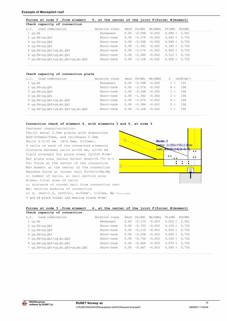
Connection check of element 4, with elements 3 and 5, at node 3
Fastener characteristics:
Two(2) metal 2.0mm plates with dimensions
BxH=350mmx155mm, and thickness 2.0mm
Nails 4.0/35 mm (d=4.0mm, L=35mm),
4 nails on each of the connected elements
Distance between nails a1=56 mm, a2=20 mm
Yield strength for plate steel fy=240 N/mm²
Net plate area (minus holes) Anet=(0.75)·b·t
Fa= force at the center of the connection
Ma= moment at the center of the connection
Maximum force at corner nail Fn=Fa/n+Ma/Wp
n: number of nails, a: nail section area
A=nxa: total area of nails
r: distance of corner nail from connection center
Wp: section modulus of connection
n= 4, (kef=1.0, neff=n), A=50mm², r=21mm, Wp =1495mm³
ı�DQG�ıG�SODWH�QRUPDO�DQG�EHDULQJ�VWUHVV�1�PPð
Forces at node 3 ,from element 4, at the center of the joint F(force) M(moment)
Check capacity of connection
/�&����/RDG�FRPELQDWLRQ����������������GXUDWLRQ�FODVV���NPRG��)D�N1���0D�N1P���)Q�N1���5G�N1�
���ȖJ�*N����������������������������������3HUPDQHQW������������������������������������������
���ȖJ�*N�ȖT�4N����������������������������6KRUW�WHUP�����������������������������������������
���ȖJ�*N�ȖT�4N����������������������������6KRUW�WHUP�����������������������������������������
���ȖJ�*N�ȖT�4NL���������������������������6KRUW�WHUP�����������������������������������������
���ȖJ�*N�ȖT�4N��ȖT�ȥR�4N������������������6KRUW�WHUP�����������������������������������������
���ȖJ�*N�ȖT�4N��ȖT�ȥR�4N������������������6KRUW�WHUP�����������������������������������������
���ȖJ�*N�ȖT�4NL�ȖT�ȥR�4N��ȖT�ȥR�4N��������6KRUW�WHUP�����������������������������������������
���������������������������������������������������������������������������������������������
30software by RUNET (c)
RUNET Norway as
09/09/2011 14:59:49C:\RUNETENG\WOOD\Examples\to net\WOODexpress Example01
WOODexpress
Example of Monopitch roof
Check capacity of connection plate
/�&����/RDG�FRPELQDWLRQ����������������GXUDWLRQ�FODVV���NPRG��)D�N1���0D�N1P�����ı���ıG�1�PPð�
���ȖJ�*N����������������������������������3HUPDQHQW����������������������������������������
���ȖJ�*N�ȖT�4N����������������������������6KRUW�WHUP���������������������������������������
���ȖJ�*N�ȖT�4N����������������������������6KRUW�WHUP���������������������������������������
���ȖJ�*N�ȖT�4NL���������������������������6KRUW�WHUP���������������������������������������
���ȖJ�*N�ȖT�4N��ȖT�ȥR�4N������������������6KRUW�WHUP���������������������������������������
���ȖJ�*N�ȖT�4N��ȖT�ȥR�4N������������������6KRUW�WHUP���������������������������������������
���ȖJ�*N�ȖT�4NL�ȖT�ȥR�4N��ȖT�ȥR�4N��������6KRUW�WHUP���������������������������������������
�������������������������������������������������������������������������������������������
31software by RUNET (c)
RUNET Norway as
09/09/2011 14:59:49C:\RUNETENG\WOOD\Examples\to net\WOODexpress Example01
WOODexpress
Example of Monopitch roof
32software by RUNET (c)
RUNET Norway as
09/09/2011 14:59:49C:\RUNETENG\WOOD\Examples\to net\WOODexpress Example01
WOODexpress
Example of Monopitch roof
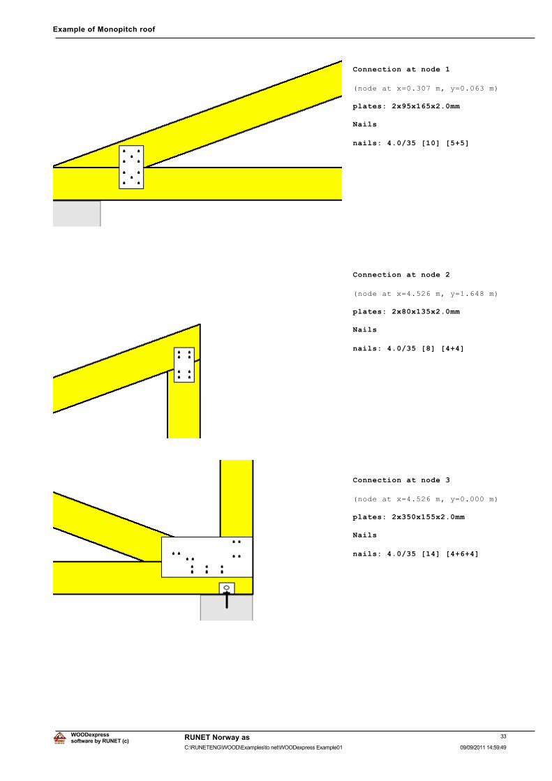
Connection at node 1
(node at x=0.307 m, y=0.063 m)
plates: 2x95x165x2.0mm
Nails
nails: 4.0/35 [10] [5+5]
Connection at node 2
(node at x=4.526 m, y=1.648 m)
plates: 2x80x135x2.0mm
Nails
nails: 4.0/35 [8] [4+4]
Connection at node 3
(node at x=4.526 m, y=0.000 m)
plates: 2x350x155x2.0mm
Nails
nails: 4.0/35 [14] [4+6+4]
33software by RUNET (c)
RUNET Norway as
09/09/2011 14:59:49C:\RUNETENG\WOOD\Examples\to net\WOODexpress Example01
WOODexpress
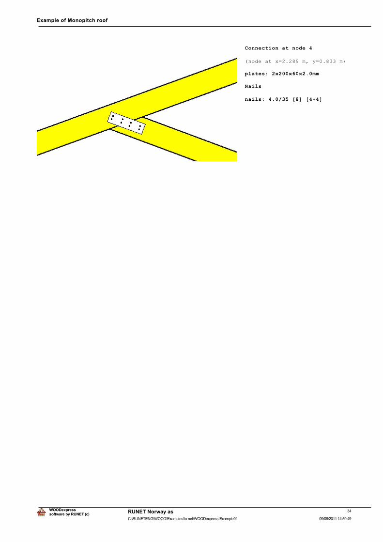
Example of Monopitch roof
Connection at node 4
(node at x=2.289 m, y=0.833 m)
plates: 2x200x60x2.0mm
Nails
nails: 4.0/35 [8] [4+4]
34software by RUNET (c)
RUNET Norway as
09/09/2011 14:59:49C:\RUNETENG\WOOD\Examples\to net\WOODexpress Example01
WOODexpress
Recommended