4.54ZONE 2/22 EX-FLOODLIGHTS
4.60ACCESSORIES
4.46EX-VESSEL LIGHT FITTING
4.28EX-FLOODLIGHTS
4.10EX-PENDANT LIGHT FITTINGS
4.41EX-CEILING LIGHT FITTINGS
E X - C E I L I N G , P E N D A N T L I G H T F I T T I N G S A N D F L O O D L I G H T S
4.50ZONE 2/22 EX-PENDANT LIGHT FITTINGS
1
2
3
4
5
6
7
8
9
10
11
12
4.2 C O O P E R C R O U S E - H I N D S G M B H
I Ex-cei l ing, pendant l ight f i t t ings and f loodl ights I
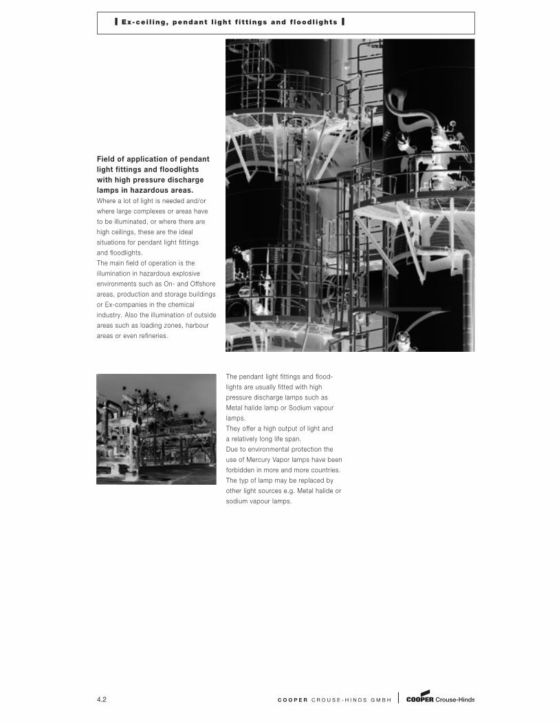
Field of application of pendant
light fittings and floodlights
with high pressure discharge
lamps in hazardous areas.
Where a lot of light is needed and/or
where large complexes or areas have
to be illuminated, or where there are
high ceilings, these are the ideal
situations for pendant light fittings
and floodlights.
The main field of operation is the
illumination in hazardous explosive
environments such as On- and Offshore
areas, production and storage buildings
or Ex-companies in the chemical
industry. Also the illumination of outside
areas such as loading zones, harbour
areas or even refineries.
The pendant light fittings and flood-
lights are usually fitted with high
pressure discharge lamps such as
Metal halide lamp or Sodium vapour
lamps.
They offer a high output of light and
a relatively long life span.
Due to environmental protection the
use of Mercury Vapor lamps have been
forbidden in more and more countries.
The typ of lamp may be replaced by
other light sources e.g. Metal halide or
sodium vapour lamps.

C O O P E R C R O U S E - H I N D S G M B H 4.3
I Ex-cei l ing, pendant l ight f i t t ings and f loodl ights I
With the CEAG pendant light fittings
and floodlights for the Zones 1, 2, 21
and 22 you have a safety assurance
even in difficult environmental con -
ditions such as high and low tempera-
ture, high humidity, dusty and aggres -
sive explosive atmospheres.
The high safety standard required is
assured for even after a long period of
usage time. A long service life and the
high reliability factor of the used electri-
cal and mechanical components makes
these lamps extremely cost-effective.
Especially the innovative illuminant
technology of the induction lamps used
in the EVQ light fittings guarantees a
lamp life expectancy of > 60,000 hours.
This makes these light fittings destinied
for usage in uncomfortable and hard to
access areas where one can efficiently
minimize the maintanance costs.
The easy changing of the lamp, for
example in the new CEAG floodlight
series FZD (you just change the com-
plete lamp module), also effectively
reduces the maintanance costs. Even
in extreme environments and tempera-
tures of -40° C you can be sure that
the light fittings will be quickly back
in use. The actual lamp replacement
can then take place in the work-shop
at a later date.
FZD flood light
Bulk head light fitting AB 05
Pendant light fitting EVQ for Induction lamps
1
2
3
4
5
6
7
8
9
10
11
12

Certified for environmental temperatures
from -55 °C up to +55° C, depend. on type
Fulfils highest requirements on corrosion
protection and mechanical stability
Robust light alloy housing
(AB 05, AB12 NAV 70)
Easy installation
High quality stainless steel screws,
easier lamp replacement
4.4
E X - C E I L I N G L I G H T F I T T I N G S
AB 05
This explosion-protected light fitting for Incan -
descent as well for high pressure discharge
lamps is designed in accordance to the ATEX-
Directive 94/9/EG.
The light fittings are fitted with an impact resis -
tant and thermally stable dome-shaped glass.
All external screws are made of high quality
stainless steel. The distinguishing characteristics
of this series are the low weight and the simple
installation.
The control gear for HPS-lamps is installed
on a removeable support in order to make the
maintenance easy.
The AB 05 series offers a wide range of applica-
tion using different type of explosion protection:
– Ex e IIC for Zone 1/21
– Ex de IIB (+H2 as an option) for Zone 1/21
– Ex nR for Zone 2/22
An internal aluminium reflector enables a well
balanced light distribution characteristic.
AB 80
Due to the flameproof design all types of incan-
descent lamps up to 100 W or suitable compact
fluorescent lamps with electronic ballast can be
used.
The AB 80 light fitting is a flat light fitting for
ceiling mounting.
Due to their robust architecture, this light fitting
is suitable for use in the chemical industry and
have been certified for usage in environments
with a temperature of up to +55° C.
AB 12 NAV 70
This compact Ex-d light fixture for high pressure
sodium lamps allows individual lighting solutions
for areas with limited mounting space. Lamp,
ballast capacitor and ignitor are incorporated
on a compact module, which allows easy
re-lamping and maintenance procedure. An
optional external reflector allows individual
illumination of working places.
AB 05, AB 80 and AB12 NAV 70
Metal Vers ion for Zone 1 and 21
I Ex-cei l ing l ight f i t t ings I
C O O P E R C R O U S E - H I N D S G M B H 4.5
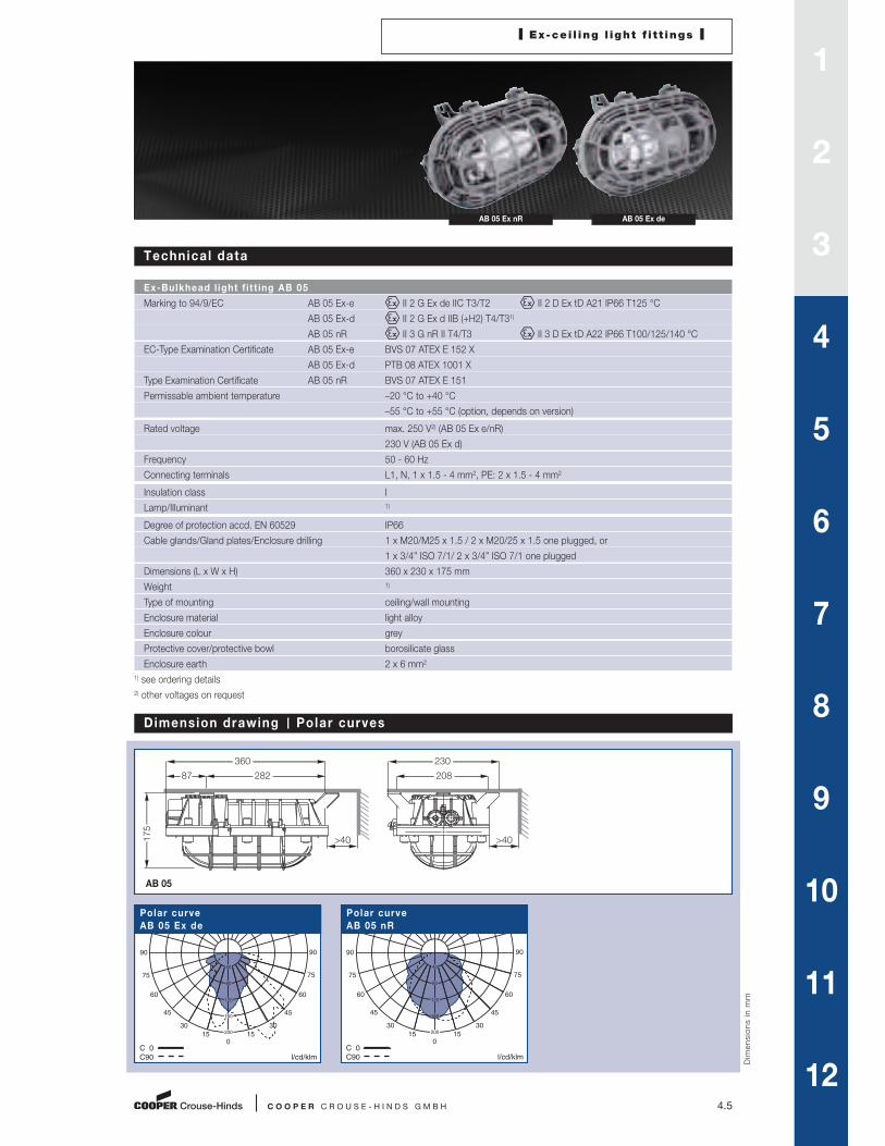
AB 05 Ex nR AB 05 Ex de
Technical data
Ex-Bulkhead l ight f i t t ing AB 05
Marking to 94/9/EC AB 05 Ex-e II 2 G Ex de IIC T3/T2 II 2 D Ex tD A21 IP66 T125 °C
AB 05 Ex-d II 2 G Ex d IIB (+H2) T4/T31)
AB 05 nR II 3 G nR II T4/T3 II 3 D Ex tD A22 IP66 T100/125/140 °C
EC-Type Examination Certificate AB 05 Ex-e BVS 07 ATEX E 152 X
AB 05 Ex-d PTB 08 ATEX 1001 X
Type Examination Certificate AB 05 nR BVS 07 ATEX E 151
Permissable ambient temperature –20 °C to +40 °C
–55 °C to +55 °C (option, depends on version)
Rated voltage max. 250 V2) (AB 05 Ex e/nR)
230 V (AB 05 Ex d)
Frequency 50 - 60 Hz
Connecting terminals L1, N, 1 x 1.5 - 4 mm2, PE: 2 x 1.5 - 4 mm2
Insulation class I
Lamp/Illuminant 1)
Degree of protection accd. EN 60529 IP66
Cable glands/Gland plates/Enclosure drilling 1 x M20/M25 x 1.5 / 2 x M20/25 x 1.5 one plugged, or
1 x 3/4” ISO 7/1/ 2 x 3/4” ISO 7/1 one plugged
Dimensions (L x W x H) 360 x 230 x 175 mm
Weight 1)
Type of mounting ceiling/wall mounting
Enclosure material light alloy
Enclosure colour grey
Protective cover/protective bowl borosilicate glass
Enclosure earth 2 x 6 mm2
1) see ordering details
2) other voltages on request
Dimension drawing Polar curves
C 0
C90
l/cd/klm
90
75
60
45
30
15
0
15
30
45
60
75
90
40
80
120
160
200
Polar curve
AB 05 Ex de
C 0
C90
l/cd/klm
90
75
60
45
30
15
0
15
30
45
60
75
90
40
80
120
160
200
Polar curve
AB 05 nR
Dimensions in m
m
AB 05
175
282
>40
87
360
208
230
>40
1
2
3
4
5
6
7
8
9
10
11
12

4.6 C O O P E R C R O U S E - H I N D S G M B H
I Ex-cei l ing l ight f i t t ings I
AB 05 Ex de AB 05 Ex nR
Ordering detai ls
Type Type of lamp Rated Temperature Cable glands/threads Weight/ Qty. Order No.
luminous class kg
flux2)
II 2 G IIC (–20 °C up to +55 °C)
AB 05 Ex de incandescent max. 60 W 710 lm T3/T21) 1 x M20 5.9 1 AB 05 531 011 0001
AB 05 Ex de incandescent max. 60 W 710 lm T3/T21) 2 x M20, 1 x Ex-e M20 5.9 1 AB 05 531 111 0001
AB 05 Ex de incandescent max. 60 W 710 lm T3/T21) 1 x M25 5.9 1 AB 05 531 021 0001
AB 05 Ex de incandescent max. 60 W 710 lm T3/T21) 2 x M25, 1 x Ex-e M25 5.9 1 AB 05 531 221 0001
II 3G Ex nR II (- 50 ºC up to + 55 ºC)
AB 05 nR 70 W HSE 5600 lm T4 1 x M20 5.4 1 AB 05 611 011 0001
AB 05 nR 70 W HSE 5600 lm T4 2 x M20, 1 x Ex-e M20 5.4 1 AB 05 611 111 0001
AB 05 nR 70 W HSE 5600 lm T4 1 x M25 5.4 1 AB 05 611 021 0001
AB 05 nR 70 W HSE 5600 lm T4 2 x M25, 1 x Ex-e M25 5.4 1 AB 05 611 221 0001
AB 05 nR 70 W HSE3) 5600 lm T4 1 x M25 5.4 1 AB 05 611 021 0002
AB 05 nR 70 W HSE3) 5600 lm T4 2 x M25, 1 x Ex-e M25 5.4 1 AB 05 611 221 0002
AB 05 nR 80 W HME 3800 lm T4 1 x M25 5.4 1 AB 05 621 021 0001
AB 05 nR 80 W HME 3800 lm T4 1 x M25, 1 x Ex-e plug 5.4 1 AB 05 621 221 0001
AB 05 nR 200 W HME 3100 lm T3 1 x M25 5.4 1 AB 05 631 021 0001
AB 05 nR 200 W HME 3100 lm T3 1 x M25 5.4 1 AB 05 631 221 0001
II 2 G IIB +H2 (- 20 ºC up to + 55 ºC)
AB 05 Ex d 70 W HSE 5600 lm T4 1 x M20 thread 6.9 1 AB 05 111 011 0001
AB 05 Ex d 70 W HSE3) 5600 lm T4 1 x M20 thread 6.9 1 AB 05 111 011 0002
AB 05 Ex d 70 W HSE 5600 lm T4 1 x Ex d NPT 1/2” thread 6.9 1 AB 05 111 031 0001
AB 05 Ex d 70 W HSE 5600 lm T4 2 x Ex d NPT 1/2” thread 6.9 1 AB 05 111 331 0001
AB 05 Ex d 70 W HSE 5600 lm T4 1 x Ex d NPT 3/4” thread 6.9 1 AB 05 111 041 0001
AB 05 Ex d 70 W HSE 5600 lm T4 2 x Ex d NPT 3/4” thread 6.9 1 AB 05 111 441 0001
AB 05 Ex d 70 W HSE3) 5600 lm T4 1 x Ex d NPT 3/4” thread 6.9 1 AB 05 211 041 0002
AB 05 Ex d 70 W HSE 5600 lm T4 1 x M20 thread 6.9 1 AB 05 211 111 0001
1 x M20 plug
AB 05 Ex d 70 W HSE3) 5600 lm T4 1 x M20 thread 6.9 1 AB 05 211 111 0002
II 2 G IIB (- 20 ºC up to + 55 ºC)
AB 05 Ex d 70 W HSE 5600 lm T4 1 x M20 thread 6.9 1 AB 05 211 011 0001
AB 05 Ex d 70 W HSE3) 5600 lm T4 1 x M20 thread 6.9 1 AB 05 211 011 0002
AB 05 Ex d 70 W HSE 5600 lm T4 1 x Ex d NPT 1/2” thread 6.9 1 AB 05 211 031 0001
AB 05 Ex d 70 W HSE 5600 lm T4 2 x Ex d NPT 1/2” thread 6.9 1 AB 05 211 331 0001
AB 05 Ex d 70 W HSE 5600 lm T4 1 x Ex d NPT 3/4” thread 6.9 1 AB 05 211 041 0001
AB 05 Ex d 70 W HSE3) 5600 lm T4 1 x Ex d NPT 3/4” thread 6.9 1 AB 05 211 041 0002
AB 05 Ex d 70 W HSE 5600 lm T4 1 x M20 thread 6.9 1 AB 05 211 111 0001
1 x M20 plug
AB 05 Ex d 70 W HSE3) 5600 lm T4 1 x M20 thread 6.9 1 AB 05 211 111 0002
AB 05 Ex d 70 W HSE 5600 lm T4 2 x Ex d NPT 3/4” thread 6.9 1 AB 05 211 441 0001
1) T3 only with lamp accd. to EN 60064 and DIN 49810 marked ”T“
2) depends on used lamps
3) for HSE lamps with integrated ignitor
Lamps and fixing accessories are not included.
Metal cable glands see page 8.10...
I Ex-cei l ing l ight f i t t ings I
C O O P E R C R O U S E - H I N D S G M B H 4.7
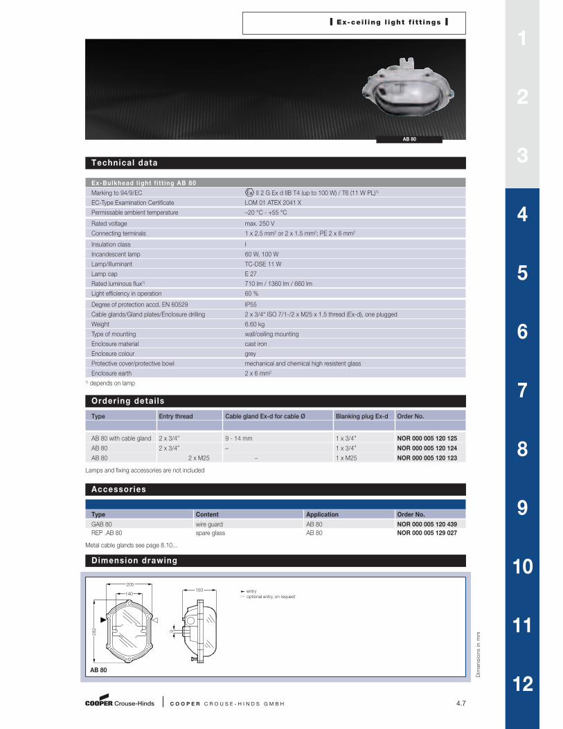
AB 80
Technical data
Ex-Bulkhead l ight f i t t ing AB 80
Marking to 94/9/EC II 2 G Ex d IIB T4 (up to 100 W) / T6 (11 W PL)1)
EC-Type Examination Certificate LOM 01 ATEX 2041 X
Permissable ambient temperature –20 °C - +55 °C
Rated voltage max. 250 V
Connecting terminals 1 x 2.5 mm2 or 2 x 1.5 mm2; PE 2 x 6 mm2
Insulation class I
Incandescent lamp 60 W, 100 W
Lamp/Illuminant TC-DSE 11 W
Lamp cap E 27
Rated luminous flux1) 710 lm / 1360 lm / 660 lm
Light efficiency in operation 60 %
Degree of protection accd. EN 60529 IP55
Cable glands/Gland plates/Enclosure drilling 2 x 3/4“ ISO 7/1-/2 x M25 x 1.5 thread (Ex-d), one plugged
Weight 6.60 kg
Type of mounting wall/ceiling mounting
Enclosure material cast iron
Enclosure colour grey
Protective cover/protective bowl mechanical and chemical high resistent glass
Enclosure earth 2 x 6 mm2
1) depends on lamp
Ordering detai ls
Type Entry thread Cable gland Ex-d for cable Ø Blanking plug Ex-d Order No.
AB 80 with cable gland 2 x 3/4” 9 - 14 mm 1 x 3/4” NOR 000 005 120 125
AB 80 2 x 3/4” – 1 x 3/4” NOR 000 005 120 124
AB 80 2 x M25 – 1 x M25 NOR 000 005 120 123
Lamps and fixing accessories are not included
Accessories
Type Content Application Order No.
GAB 80 wire guard AB 80 NOR 000 005 120 439
REP .AB 80 spare glass AB 80 NOR 000 005 129 027
Metal cable glands see page 8.10...
Dimension drawing
Dimensions in m
m
AB 80
282
205
140150
9
entry
optional entry, on request
1
2
3
4
5
6
7
8
9
10
11
12

4.8 C O O P E R C R O U S E - H I N D S G M B H
I Ex-Bulkhead l ight f i t t ing I
AB 12 NAV 70
Technical data
Ex-Bulkhead l ight f i t t ing AB 12 NAV 70
Marking to 94/9/EC II 2 G Ex d IIC / IIB T3 / II 2 D Ex tD A21 IP67 T160 °C
EC-Type Examination Certificate LOM 02 ATEX 2013 X
IECEx Certificate of Conformity IECEx BKI 07.0008X
Marking accd. to IECEx Ex d IIC / IIB T3
Permissible amient temperature –20 °C to +55 °C – Gas group IIC
–45 °C to +55 °C – Gas group IIB
Rated voltage 230 V1)
Rated current 0,36 A
Frequency 50 Hz
Power factor cos ϕ ≥ 0,9
Connecting terminals L1, N, PE: 2 x 2.5 mm2, PE 2 x 6 mm2
Insulation class I
Lamp/Illuminant HSE 70 W
Lamp cap E 27
Rated luminous flux1) 5600 lm
Light efficiency in operation 70 %
Degree of protection accd. EN 60529 IP67
Cable glands/Gland plates/Enclosure drilling 2 x 3/4“ ISO 7/1 thread (Ex-d) one plugged
Weight 5.30 kg
Type of mounting Wall/ceiling mounting
Enlcosure material light alloy
Enclosure colour grey
Protective cover Borosilicate glass tube
1) depends on lamp

C O O P E R C R O U S E - H I N D S G M B H 4.9
Ordering detai ls
Type Entry thread Cable gland Blanking plug Qty. Order No.
Ex-d for cable Ø Ex-d
Group IIC - NORMAL (ambient temperature) (–20 °C to +55 °C)
AB 12 NAV 70 + PE 2 x 3/4” 9 - 14 1 x 3/4” 1 NOR 000 005 060 071
AB 12 NAV 70 2 x 3/4” – 1 x 3/4” 1 NOR 000 005 060 070
Group IIB - LOW (ambient temperature) (up to –45 °C)
AB 12 NAV 70 2 x 3/4” – 1 x 3/4” 1 NOR 000 005 060 072
Lamps and fixing accessories are not included
Dimensions drawing Polar curve
Dimensions in m
m
AB 12 NAV 70
C 0
C90
l/cd/klm
90
75
60
45
30
15
0
15
30
45
60
75
90
40
80
120
160
200
Polar curve
AB 12 NAV 70
103
236
236
144
140
optional entry, on request
entry
405
460
M8x12mm
I Ex-Bulkhead l ight f i t t ing I
AB 12 NAV 70
Accessories
AB 12 NAV 70
Type Content Order No.
D 92 Ceiling bracket with screws and polyamide washer (CrNi, 2 pcs.) 2 2480 092 000
A5 Ceiling bracket hot galvanized (1 pc.) NOR 000 005 009 162
BFP45 Wall bracket 45° hot galvanized (1 pc.) NOR 000 005 009 196
RAB 108 Reflector AISI 304 NOR 003 045 060 471
RAB 108 Reflector AISI 304 + guard (steel white epoxy coating) NOR 003 045 060 819
RAB 108 Reflector AISI 316 NOR 003 165 060 471
RAB 108 Reflector AISI 316 + guard (steel white epoxy coating) NOR 003 165 060 819
Metal cable glands see page 8.10...
1
2
3
4
5
6
7
8
9
10
11
12

4.10
For environmental temperatures
range of –50 °C up to +55° C (EVQ excluded)
Safety Standard IP67
Robust light alloy housing
Easy opening of lamp compartment
4.10
E X - P E N D A N T L I G H T F I T T I N G S
All explosion-protected pendant light fittings
for Incandescent, high pressure discharge and
Induction lamps are in accordance with the
ATEX-Directive 94/9/EG.
AB 50/SPG 1N and AB51
Due to their compact design the series AB 50,
SPG 1N and AB 51 are designed for individual
illumination of a local area. Beside the copper-
free aluminium housings all external screws are
made of stainless steel. The protective glass
dome is made of borosilicate glass which has
a high mechanical and thermic stability. This
ensures a save use even in harsh environmental
areas. Most of the world-wide field conditions
can be accepted by the large permissible
ambient temperature range from –50 °C
up to +55 °C.
EVI and EV…
The housing is made of a copper-free aluminium.
The ballast for the high pressure discharge
lamps (EVM/EVS/EVH) is thermically separated
in its own compartment in the top part of the
housing. The dome-shaped glass enclosure is
made of borosilicate glass which has a high
mechanical and thermic stability. All external
screws and the reflector are made of stainless
steel. The lamp replacement is done by opening
the PTFE coated connection ring. Both the glass
enclosure and the connection ring are hinged
for easy access. Due to their robust architecture,
these light fittings are suitable for use in the
chemical industry and have been certified for
usage in environments with a temperature
of up to +55° C (EVQ excluded). The new light
fitting EVQ, designed for lamp replacement in
> 60000 hour intervals are fitted with induction
lamps and a high-frequency generator.
for incandescent and h igh pressure d ischarge lamps up to 500 W
Metal vers ion for Zone 1/21

C O O P E R C R O U S E - H I N D S G M B H 4.11
I Ex-Pendant l ight f i t t ings I
AB 50 IXMSPG 1N AB 50 IU
Technical data
AB 50 SPG 1N
Marking to 94/9/EC II 2 G Ex d IIC T3 (direct entry IU); T4 with 60 W at tamp +40 °C1)
(new standard – applied for) II 2 G Ex de IIC T3 (indirect entry IXM)
II 2 D Ex tD IP67 T180 °C, T130 with 60 W at +40 °C
EC-Type Examination Certificate LOM 02 ATEX 2018 X
Permissible ambient temperature -20 °C to +55 °C
-50 °C to +55 °C (option: AB 50)
Rated voltage max. 250 V
Power consumption max. 100 W
Connecting terminals 1 x 2.5 mm2 / 2 x 1.5 mm2 (IU and SPG1N), 2 x 2.5 mm2, PE 2 x 6 mm2 (IXM)
Insulation class I
Incandescent lamp 60 W, 100 W, 75 W halogene2)
Lamp cap E 27
Rated luminous flux1) 710 lm / 1360 lm
Light efficiency in operation 68 %
Degree of protection accd. EN 60529 IP67
Cable glands/Gland plates/Enclosure drilling 2 x 3/4” ISO 7/1-thread (Ex-d), one plugged (UI) /
2 x M25 x 1,5 (IXM), SPG1N incl. cable gland
Dimensions (L x W x H) see dimension drawing
Weight see table
Type of mounting ceiling mounting
Enclosure material light alloy
Enclosure colour grey
Protective cover/protective bowl borosilicate glass
1) depends on lamp
2) 75 W halogene lamp max ta = +40 °C
1
2
3
4
5
6
7
8
9
10
11
12

4.12 C O O P E R C R O U S E - H I N D S G M B H
I Ex-Pendant l ight f i t t ings I
AB 50 IU AB 50 IXM
Ordering detai ls
Type Entry thread Cable gland Blanking plug Weight Order No.
for cable Ø
(T ambient -20 °C to +55 °C)
AB 50 IU (direct entry) 2 x 3/4” 9 - 14 mm Ex-d 1 x 3/4” Ex-d 1.6 kg NOR 000 115 110 292
AB 50 IU (direct entry) 2 x 3/4” – 1 x 3/4” Ex-d 1.5 kg NOR 000 115 110 289
AB 50 IXM (indirect entry) 2 x M25 x 1.5 9 - 14 mm Ex-e 1 x M25 x 1.5 Ex-e 2.3 kg NOR 000 115 110 321
AB 50 IXM (indirect entry) 2 x M25 x 1.5 – 1 x M25 x 1.5 Ex-e 2.2 kg NOR 000 115 110 320
SPG 1N (portable light fixture) 1 x 3/4” 9 - 14 mm Ex-d – 2.2 kg NOR 000 005 110 745
(T ambient -50 °C to +55 °C)
AB 50 IU (direct entry) 2 x 3/4” – 1 x 3/4” Ex-d 1.6 kg NOR 000 115 110 389
AB 50 IXM (indirect entry) 2 x M25 x 1.5 – 1 x M25 x 1.5 Ex-e 2.2 kg NOR 000 115 110 420
Lamps and fixing accessories are not included
Accessories
AB 50/SPG 1N
Type Content Application Order No.
REP AB 50 Spare glass AB 50 NOR 000 115 110 874
WG Wire guard, galvanized AB 50 NOR 000 115 110 875
ER External reflector, coated AB 50 NOR 000 115 110 718
CEV / AB Eye bolt galvanized AB 50 NOR 000 005 110 852
AS. EV Ceiling bracket, galvanized AB 50 NOR 000 005 110 828
Metal cable glands see page 8.10...
Dimensions drawing Polar curve
Dim
en
sio
ns
in
mm
Ø125
254
Ø125
400
125
358
entry
optional entry, on request
AB 50 IU AB 50 IXM SPG 1N
SPG 1N
90
120 120
60
30
0
30
60
90
C 0
C90
l/cd/klm
25
50
75
100
125
Polar curve
AB 50 IU

C O O P E R C R O U S E - H I N D S G M B H 4.13
I Ex-Pendant l ight f i t t ings I
AB 51 M/S ...V AB 51 IX AB 51 IU
Technical data
AB 51 IU AB 51 IX AB 51 M/S. . .
Marking to 94/9/EC II 2 G Ex de IIC T1) (indirect entry IX) / Ex d IIC T1) (direct entry)1)
(new standard – applied for) II 2 D Ex tD A21 IP67 T1) °C
EC-Type Examination Certificate LOM 02 ATEX 2020 X
IECEx Certificate of Conformity IECEx BKI 07.0028X
Marking acc. to IECEx Ex d/de IIC T1)
Ex tD A21 IP67 T1)
Permissible ambient temperature -20 °C to +55 °C
-45 °C to +55 °C (AB 51 M/S)
-50 °C to +55 °C (option)
Rated voltage max. 250 V (AB 51..) / 230 V AC AB 51 M/S3)
Power factor cos ϕ ≥ 0.85 (AB 51 M/S)
Connecting terminals 1 x 2.5 mm2 / 2 x 1.5 mm2 (IU), 2 x 2.5 mm2 (IX and M/S), PE ext. 2 x 6 mm2
Insulation class I
Lamp/Illuminant 1)
Lamp cap E 27
Rated luminous flux2) 2)
Light efficiency in operation 75 %
Degree of protection accd. EN 60529 IP67
Cable glands/Gland plates/Enclosure drilling 2 x 3/4” ISO 7/1-thread (Ex-d), one plugged (UI and M/S) /
2 x M25 x 1.5 one plugged (IX)
Dimensions (L x W x H) 260 mm x Ø 205 mm (IU), 400 x Ø 205 mm (IX), 425 x Ø 205 (M/S)
Weight see ordering information
Type of mounting ceiling mounting
Enclosure material light alloy
Enclosure colour grey
Protective cover/protective bowl borosilicate glass
Addit ional lamp data
Lamp Luminous Power Temperature class II 2 G Max. surface temp. II 2 D
flux2) Tambient ≤ 40 °C Tambient > 40 °C Tambient ≤ 40 °C Tambient > 40 °C
Incandescent IGA 65 2200 lm 150 W T3 T3 T 132 °C T 147 °C
Incandescent IGA 80 3100 lm 200 W T3 T3 T 137 °C T 152 °C
Halogene lamp IQT 1100 lm 75 W T5 T4 T 88 °C T 103 °C
Halogene lamp IQT 2500 lm 150 W4) T4 T3 T 123 °C T 138 °C
Compact Fuorescent Lamp TC-TSE 900/1200 lm 15 - 20 W5) T6 T6 T 60 °C T 75 °C
High pressure mercury vapor
mixed light HME-SB 1100 lm 100 W T4 T4 T 110 °C T 125 °C
High pressure mercury vapor
mixed light HME-SB 3100 lm 160 W T3 T3 T 127 °C T 142 °C
High pressure mercury vapor HME 3800 lm 80 W T4 T4 T 112 °C T 127 °C
High pressure mercury vapor HME 6300 lm 125 W T3 T3 T 127 °C T 142 °C
High pressure sodium lamp HSE 3400 lm 50 W T5 T4 T 86 °C T 101 °C
High pressure sodium lamp HSE 5600 lm 70 W T4 T4 T 97 °C T 112 °C
1) see table
2) depends on lamp
3) others on request
4) Tamp max. +40 °C
5) Tamp max. +30 °C
1
2
3
4
5
6
7
8
9
10
11
12

4.14 C O O P E R C R O U S E - H I N D S G M B H
I Ex-Pendant l ight f i t t ings I
AB 51 IU AB 51 IX AB 51 M/S ...V
Ordering detai ls
Type Lamp Entry thread Cable gland Blanking plug Weight Order No.
for cable Ø
(T ambient -20 °C up to +55 °C)
AB 51 IU (direct entry) all 2 x 3/4” – 1 x 3/4” Ex-d 3.6 kg NOR 000 115 110 396
AB 51 IX (indirect entry) all 2 x M25 x 1.5 – 1 x M25 Ex-e 4.5 kg NOR 000 115 110 437
AB 51 M 125 V (direct entry)2) 125 W HME 2 x 3/4” – 1 x 3/4” Ex-d 7.5 kg NOR 000 115 110 890
AB 51 S 70 V (direct entry)2) 70 W HSE 2 x 3/4” – 1 x 3/4” Ex-d 7.5 kg NOR 000 115 110 903
(T ambient -50 °C up to +55 °C)
AB 51 IU (direct entry) all 2 x 3/4” – 1 x 3/4” Ex-d 3.6 kg NOR 000 115 110 397
AB 51 IX (indirect entry) all 2 x M25 x 1.5 – 1 x M25 Ex-e 4.5 kg NOR 000 115 110 438
(T ambient -45 °C up to +55 °C)
AB 51 M 125 V (direct entry)2) 125 W HME 2 x 3/4” – 1 x 3/4” Ex-d 7.5 kg NOR 000 115 110 891
AB 51 S 70 V (direct entry)2) 70 W HSE 2 x 3/4” – 1 x 3/4” Ex-d 7.5 kg NOR 000 115 110 870
Lamps and fixing accessories are not included
2) including flameproof enclosure with complete control gear
Accessories
AB 51
Content Application Order No.
Spare glass with metal ring AB 51 NOR 000 115 110 873
Wire guard AB 51 NOR 000 005 110 860
External reflector AB 51 NOR 000 005 110 894
Ceiling bracket ANSI 316 AB 51 NOR 003 165 110 000
Eye bolt ANSI 316 AB 51 NOR 003 165 110 001
Dimensions drawing Polar curve
Dim
en
sio
ns
in
mm
AB 51 IU AB 51 IX AB 51 ..V
C 0
l/cd/klm
90
75
60
45
30
15
0
15
30
45
60
75
90
25
50
75
100
125
Polar curve
AB 51 IU
Ø210 Ø210 Ø210
430
406
406
optional entry, on request
entry

C O O P E R C R O U S E - H I N D S G M B H 4.15
I Ex-Pendant l ight f i t t ings I
EVI 200 XMEVI 500 UDEVI 500 XM EVI 200 UD
Technical data
EVI 200 EVI 500
Marking to 94/9/EC II 2 G Ex d IIC T1) (direct entry UD)
(new standard – applied for) II 2 G Ex de IIC T1) (indirect entry XM)
II 2 D Ex tD A21 IP67 T1) °C
EC-Type Examination Certificate LOM 02 ATEX 2012 X
IECEx Certificate of Conformity IECEx BKI 07.0031X
Marking acc. to IECEx Ex d / de IIC T1)
Ex tD A21 IP67 T1)
Permissible ambient temperature -20 °C to +55 °C
-50 °C to +55 °C
Rated voltage max. 250 V
Connecting terminals 1 x 2.5 mm2 / 2 x 1.5 mm2 (UD), 2 x 2.5 mm2 (XM); PE ext. 2 x 6 mm2
Insulation class I
Lamp/Illuminant 1)
Lamp cap E 27 (EVI 200) / E 40 (EVI 500)
Rated luminous flux 1)
Light efficiency in operation 75 %
Degree of protection accd. EN 60529 IP67
Cable glands/Gland plates/Enclosure drilling 2 x 3/4” ISO 7/1-thread (Ex-d), one plugged (UD) / 2 x M25 x 1.5, on plugged (XM)
Dimensions (L x W x H) 280 mm x Ø 245 mm (200 UD), 400 x Ø 225 mm (200 XM)
340 mm x Ø 300 mm (500 UD), 460 x Ø 300 mm (500 XM)
Weight see ordering information
Type of mounting ceiling mounting
Enclosure material light alloy
Enclosure colour grey
Protective cover/protective bowl borosilicate glass
Addit ional lamp data
Lamp Luminous Power Type Temperature class II 2 G Max. surface temp. II 2 D
flux2) Tambient ≤ +40 °C Tambient ≤ +55 °C Tambient ≤ +40 °C Tambient ≤ +55 °C
Incandescent IGA 65 2200 lm 150 W EVI 200 T4 T4 T105 ºC T120 ºC
Incandescent IGA 80 3100 lm 200 W EVI 200 T4 T4 T115 ºC T130 ºC
Incandescent IGA 90 5000 lm 300 W EVI 500 T4 T4 T115 ºC T130 ºC
Incandescent IGA 110 8400 lm 500 W EVI 500 T3 T3 T155 ºC T170 ºC
High pressure mercury
vapor mixed light HME-SB 3100 lm 160 W EVI 200 T4 T3 T125 ºC T140 ºC
High pressure mercury
vapor mixed light HME-SB 5600 lm 250 W EVI 500 T4 T3 T125 ºC T140 ºC
High pressure mercury vapor HME 3800 lm 80 W EVI 200 T4 T4 T115 ºC T130 ºC
High pressure mercury vapor HME 6300 lm 125 W EVI 200 T4 T4 T115 ºC T130 ºC
High pressure mercury vapor HME 13000 lm 250 W EVI 500 T4 T3 T125 ºC T140 ºC
High pressure sodium lamp HSE 5600 lm 70 W EVI 200 T5 T4 T 95 ºC T110 ºC
High pressure sodium lamp HSE 14000 lm 150 W EVI 500 T5 T4 T 90 ºC T105 ºC
High pressure sodium lamp HSE 25000 lm 250 W EVI 500 T4 T4 T125 ºC T140 ºC
High pressure Metal Halide HIE 17000 lm 250 W EVI 500 T4 T3 T125 ºC T140 ºC
1) see table
2) depends on lamp
1
2
3
4
5
6
7
8
9
10
11
12

4.16 C O O P E R C R O U S E - H I N D S G M B H
I Ex-Pendant l ight f i t t ing I
Ordering detai ls
Type1) Entry thread Cable gland Blanking plug Weight Order No.
for cable Ø kg
(T ambient -20 °C to +55 °C)
EVI 200 UD (direct entry) 2 x 3/4” 9 -14 mm Ex-d 1 x 3/4” Ex-d 8.30 NOR 000 005 110 754
EVI 200 UD (direct entry) 2 x 3/4” – 1 x 3/4” Ex-d 8.20 NOR 000 005 110 753
EVI 500 UD (direct entry) 2 x 3/4” 9 -14 mm Ex-d 1 x 3/4” Ex-d 12.90 NOR 000 005 110 762
EVI 500 UD (direct entry) 2 x 3/4” – 1 x 3/4” Ex-d 12.80 NOR 000 005 110 761
EVI 200 XM (indirect entry) 2 x M25 x 1.5 9 -14 mm Ex-e 1 x M25 Ex-e 9.10 NOR 000 005 110 941
EVI 200 XM (indirect entry) 2 x M25 x 1.5 – 1 x M25 Ex-e 9.00 NOR 000 115 110 941
EVI 500 XM (indirect entry) 2 x M25 x 1.5 9 -14 mm Ex-e 1 x M25 Ex-e 13.70 NOR 000 005 110 942
EVI 500 XM (indirect entry) 2 x M25 x 1.5 – 1 x M25 Ex-e 13.60 NOR 000 115 110 942
(T ambient -50 °C to +55 °C)
EVI 200 UD (direct entry) 2 x 3/4” – 1 x 3/4” Ex-d 8.20 NOR 000 115 110 753
EVI 500 UD (direct entry) 2 x 3/4” – 1 x 3/4” Ex-d 12.80 NOR 000 005 110 763
EVI 200 XM (direct entry) 2 x 3/4” – 1 x 3/4” Ex-d 9.00 NOR 000 115 110 943
EVI 500 XM (direct entry) 2 x 3/4” – 1 x 3/4” Ex-d 13.60 NOR 000 115 110 944
1) Versions for high pressure lamps (HME, HSE, HIE): flameproof ballast enclosure not included
Lamps and fixing accessories are not included
Accessories
EVI 200, EVI 500
Type Content Application Order No.
REP 200 Spare Glass EVI 200 NOR 000 005 110 969
REP 500 Spare glass EVI 500 NOR 000 005 110 977
G. EV 200 Wire Guard EVI 200 NOR 000 005 110 860
G. EV 500 Wire Guard EVI 500 NOR 000 005 110 878
PC. EV 200 External reflector EVI 200 / EVQ 55 NOR 000 005 110 894
PC. EV 500 External reflector EVI 500 / EVQ 85 NOR 000 005 110 901
KEY, EV Lamp key EV ... NOR 000 005 110 886
CEV/AB Eye bolt EV ... NOR 000 005 110 852
AS. EV Ceiling bracket,adjustable EV ... NOR 000 005 110 828
SPU. EV Wall mounting barcket EV ... NOR 000 005 110 951
BC. EV Pole mounting bracket EV ... NOR 000 005 110 836
SP. EV 200 Wall mounting bracket EVI 200 NOR 000 005 110 935
SP. EV 500 Wall mounting bracket EVI 500 NOR 000 005 110 943
Metal cable glands see page 8.10...
EVI 500 UDEVI 200 XMEVI 200 UD EVI 500 XM

I Ex-Pendant l ight f i t t ing I
C O O P E R C R O U S E - H I N D S G M B H 4.17
Dimensions drawing Polar curve
Dim
en
sio
ns
in
mm
EVI 200 UD
BC. EV/AB
KEY.EV CEV/AB AS.EV/AB
SP.EV 200/500
EVI 200 XM EVI 500 UD EVI 500 XM
280
Ø 245
400
Ø 245340
Ø 300
460
Ø 300
entry
optional entry, on request
90
120 120
60
30
0
30
60
90
C 0
C90
l/cd/klm
20
40
60
80
100
Polar curve EVI 200/500
without external ref lector
C 0
l/cd/klm
90
75
60
45
30
15
0
15
30
45
60
75
90
200
400
600
800
1000
Polar curve EVI 200/500
with external ref lector
EVI 200 XMEVI 500 XMEVI 500 UD EVI 200 UD
3/4´´ ø 12
140
50
3/4´´
12.7
245
300 ø
140
17012
235
285
350
100
45
11.5
1
2
3
4
5
6
7
8
9
10
11
12

EVQ 85 UDEVQ 55 XMEVQ 55 UD EVQ 85 XM
4.18 C O O P E R C R O U S E - H I N D S G M B H
I Ex-Pendant l ight f i t t ing I
Technical data
EVQ QL-lamps
Marking to 94/9/EC II 2 G Ex d IIC T6 (direct entry UD)
(new standard – applied for) II 2 G Ex de IIC T6 (indirect entry XM)
II 2 D Ex tD A21 IP67 T85 °C
EC-Type Examination Certificate LOM 02 ATEX 2012 X
IECEx Certificate of Conformity IECEx BKI 07.0031X
Marking acc. to IECEx Ex d / de IIC T6
Permissible ambient temperature -20 °C to +55 °C
Rated voltage 230 V AC/DC
Rated current 0.26 A (55 W), 0.40 A (85 W)
Frequency 50/60 Hz
Power factor cos ϕ > 0.96
Circuit electronic HF generator
Connecting terminals 1 x 2.5 mm2 / 2 x 1.5 mm2 (UD), 2 x 2.5 mm2 (XM); PE ext. 2 x 6 mm2
Insulation class I
Lamp/Illuminant Induction lamp 55/85 W with coupler
Rated luminous flux 55 W: 3500 lm / 85 W: 6000 lm
Light efficiency in operation 66 %
Degree of protection accd. EN 60529 IP67
Cable glands/Gland plates/Enclosure drilling 2 x 3/4” ISO 7/1-thread (Ex-d), one plugged (UD),
2 x M25 thread (Ex-e), one plugged (XM)
Dimensions (L x W x H) 280 mm x Ø 245 mm (55 UD), 400 x Ø 225 mm (55 XM),
340 mm x Ø 300 mm (85 UD), 460 x Ø 300 mm (85 XM),
Weight see ordering information
Type of mounting ceiling mounting
Enclosure material light alloy
Enclosure colour grey, PTFE (optional)
Protective cover/protective bowl borosilicate glass, opaque (clear on request)
Fixing accessories are not included, included lamps and HF generator

I Ex-Pendant l ight f i t t ing I
C O O P E R C R O U S E - H I N D S G M B H 4.19
EVQ 55 XMEVQ 85 UDEVQ 85 XM EVQ 55 UD
Ordering detai ls
Type Entry thread Cable gland Blanking plug Weight Order No.
for cable Ø kg
EVQ 55 UD (direct entry 2 x 3/4” 9 -14 mm Ex-d 1 x 3/4” Ex-d 9.10 NOR 000 115 110 851
EVQ 55 UD (direct entry 2 x 3/4” – 1 x 3/4” Ex-d 9.00 NOR 000 115 110 850
EVQ 85 UD (direct entry 2 x 3/4” 9 -14 mm Ex-d 1 x 3/4” Ex-d 12.9 NOR 000 115 110 853
EVQ 85 UD (direct entry 2 x 3/4” – 1 x 3/4” Ex-d 12.8 NOR 000 115 110 852
EVQ 55 XM (indirect entry 2 x M25 x 1.5 9 -14 mm Ex-e 1 x M25 Ex-e 9.90 NOR 000 115 110 855
EVQ 55 XM (indirect entry 2 x M25 x 1.5 – 1 x M25 Ex-e 9.80 NOR 000 115 110 854
EVQ 85 XM (indirect entry 2 x M25 x 1.5 9 -14 mm Ex-e 1 x M25 Ex-e 13.70 NOR 000 115 110 857
EVQ 85 XM (indirect entry 2 x M25 x 1.5 – 1 x M25 Ex-e 13.60 NOR 000 115 110 856
Accessories
EVQ 55, EVQ 85
Type Content Application Order No.
G. EV 200 Wire Guard EVQ 55 NOR 000 005 110 860
G. EV 500 Wire Guard EVQ 85 NOR 000 005 110 878
PC. EV 200 External reflector EVI 200 / EVQ 55 NOR 000 005 110 894
PC. EV 500 External reflector EVI 500 / EVQ 85 NOR 000 005 110 901
KEY, EV Lamp key EV ... NOR 000 005 110 886
CEV/AB Eye bolt EV ... NOR 000 005 110 852
AS. EV Ceiling bracket, adjustable EV ... NOR 000 005 110 951
SPU. EV Wall mounting barcket EV ... NOR 000 005 110 828
BC. EV Pole mounting bracket EV ... NOR 000 005 110 836
SP. EV 200 Wall mounting bracket EVQ 55 NOR 000 005 110 935
SP. EV 500 Wall mounting bracket EVQ 85 NOR 000 005 110 943
Metal cable glands see page 8.10...
Dimensions drawing Polar curve
Dim
en
sio
ns
in
mm
280
Ø 245
400
Ø 245
340
Ø 300
460
Ø 300entry
optional entry, on request
EVQ 55 UD
Dimensions for Accessories see page 5.17
EVQ 55 XM EVQ 85 UD EVQ 85 XM
90
120 120
60
30
0
30
60
90
C 0
C90
l/cd/klm
20
40
60
80
100
Polar curve EVQ 55/85
without external ref lector
90
120 120
60
30
0
30
60
90
C 0
C90 l/cd/klm
100
200
300
400
Polar curve EVQ 55/85
with external ref lector
1
2
3
4
5
6
7
8
9
10
11
12

4.20 C O O P E R C R O U S E - H I N D S G M B H
Technical data
EVM EVS EVH
Marking to 94/9/EC II 2 G Ex de IIC T1)
(new standard – applied for) II 2 D Ex tD A21 IP66 T1) °C
EC-Type Examination Certificate LOM 02 ATEX 2012 X
IECEx Certificate of Conformity IECEx BKI 07.0031X
Marking acc. to IECEx Ex de IIC T1)
Ex tD A21 IP67 T1)
Permissible ambient temperature -20 °C to +55 °C
-45 °C to +55 °C (option)
Rated voltage 230 V AC2)
Rated current 1)
Frequency 50 Hz2)
Power factor cos ϕ > 0.85
Circuit electromagnetic circuit
Connecting terminals 3 x (2 x 2.5 mm2); PE extern. 2 x 6 mm2
Insulation class I
Lamp cap E 27 (EV. 70 ... 125), E 40 (EV 150 ... 250)
Light efficiency in operation 76 %
Degree of protection accd. EN 60529 IP67
Cable glands/Gland plates/Enclosure drilling 2 x M25 threads (Ex-e), one plugged
Dimensions (L x W x H) 480 mm x Ø 245 mm (EV.. 70-125 ZM)
560 mm x Ø 300 mm (EV.. 150-250 ZM
Weight see ordering information
Type of mounting ceiling mounting
Enclosure material light alloy
Enclosure colour grey
Protective cover/protective bowl borosilicate glass
1) see ordering details
2) other voltages or frequencies on request
Addit ional lamp data
Lamp Luminous Power Type Temperature class II 2 G Max. surface temp. II 2 D
flux3) Tambient ≤ 40 °C Tambient > 40 °C Tambient ≤ 40 °C Tambient > 40 °C
High pressure mercury vapor HME 6300 lm 125 W EVM 125 ZM T4 T4 T115ºC T130ºC
High pressure mercury vapor HME 13000 lm 250 W EVM 250 ZM T4 T3 T125ºC T140°C
High pressure sodium lamp HSE 5600 lm 70 W EVS 70 ZM T5 T4 T95ºC T110ºC
High pressure sodium lamp HSE 14000 lm 150 W EVS 150 ZM T5 T4 T90ºC T105ºC
High pressure sodium lamp HSE 25000 lm 250 W EVS 250 ZM T4 T4 T115ºC T130ºC
High pressure Metal Halide HIE 17000 lm 250 W EVH 250 ZM T4 T3 T125ºC T140ºC
3) depends on used lamps
I Ex-Pendant l ight f i t t ing I
EV ... 70 - 125 ZM EV ... 150 - 250 ZM

I Ex-Pendant l ight f i t t ing I
C O O P E R C R O U S E - H I N D S G M B H 4.21
EV ... 150 - 250 ZM EV ... 70 - 125 ZM
Ordering detai ls
Type Lamp Rated current Cable gland Ex-e Weight Order No.
for cable Ø kg
(T ambient -20 °C to +55 °C)
EVM 125 ZM HME 125W 1.10 A 9 -14 mm 14.1 NOR 000 115 110 079
EVM 125 ZM HME 125W 1.10 A – 14.0 NOR 000 115 110 879
EVM 250 ZM HME 250W 2.10 A 9 -14 mm 22.4 NOR 000 115 110 080
EVM 250 ZM HME 250W 2.10 A – 22.5 NOR 000 115 110 881
EVS 70 ZM HSE 70W 0.35 A 9 -14 mm 14.1 NOR 000 115 110 086
EVS 70 ZM HSE 70W 0.35 A – 14.0 NOR 000 115 110 880
EVS 150 ZM HSE 150W 0.96 A 9 -14 mm 22.4 NOR 000 115 110 087
EVS 150 ZM HSE 150W 0.96 A – 22.4 NOR 000 115 110 883
EVS 250 ZM HSE 250W 1.70 A 9 -14 mm 22.4 NOR 000 115 110 088
EVS 250 ZM HSE 250W 1.70 A – 22.4 NOR 000 115 110 882
EVH 250 ZM HIT 250W 1.80 A 9 -14 mm 22.4 NOR 000 115 110 046
EVH 250 ZM HIT 250W 1.80 A – 22.4 NOR 000 115 110 945
(T ambient -45 °C to +55 °C)
EVM 125 ZM HME 125 W 0.96 A – 14.0 NOR 000 115 110 884
EVM 250 ZM HME 250 W 0.96 A – 22.4 NOR 000 115 110 885
EVS 70 ZM HSE 70 W 1.70 A – 14.0 NOR 000 115 110 886
EVS 150 ZM HSE 150 W 1.70 A – 22.4 NOR 000 115 110 887
EVS 250 ZM HSE 250 W 1.80 A – 22.4 NOR 000 115 110 888
EVH 250 ZM HIT 250 W 1.80 A – 22.4 NOR 000 115 110 889
Lamps and fixing accessories are not included
1
2
3
4
5
6
7
8
9
10
11
12

4.22 C O O P E R C R O U S E - H I N D S G M B H
I Ex-Pendant l ight f i t t ing I
EV ... 70 - 125 ZM EV ... 150 - 250 ZM
Accessories
EVM, EVS, EVH
Type Content Application Order No.
REP 200 Space glass EV.. 70-125 .. NOR 000 005 110 969
REP 500 Spare glass EV.. 150-250 .. NOR 000 005 110 977
G. EV 200 Wire guard EV.. 70-125 .. NOR 000 005 110 860
G. EV 500 Wire guard EV.. 150-250 .. NOR 000 005 110 878
PC. EV 200 External reflector EV.. 70-125 .. NOR 000 005 110 894
PC. EV 500 External reflector EV.. 150-250 .. NOR 000 005 110 901
KEY, EV Lamp key EV.. NOR 000 005 110 886
CEV/AB Eye bolt EV.. NOR 000 005 110 852
AS. EV Ceiling bracket, adjustable EV.. NOR 000 005 110 951
SPU. EV Ø 44 – 64 mm Wall mounting barcket EV.. NOR 000 005 110 828
BC. EV Pole mounting bracket EV.. NOR 000 005 110 836
SP. EV 200 Wall mounting bracket EV 70..-125 .. NOR 000 005 110 935
SP. EV 500 Wall mounting bracket EV 150..-250 .. NOR 000 005 110 943
Metal cable glands see page 8.10...
Dimensions drawing
Dim
en
sio
ns
in
mm
EV... 70 - 125 ZM EV... 150 - 250 ZM
460
Ø 245
560
Ø 300
90
120 120
60
30
0
30
60
90
C 0
C90
l/cd/klm
20
40
60
80
100
Polar curve EV 200/500
without external ref lector
C 0
l/cd/klm
90
75
60
45
30
15
0
15
30
45
60
75
90
200
400
600
800
1000
Polar curve EV 200/500
with external ref lector
BC. EV
KEY.EV CEV/AB AS.EVSP.EV 200/500
3/4´´ ø 12
140
50
3/4´´
12.7245
300 ø
140
17012
235
285
350
100
45
11.5
entry

C O O P E R C R O U S E - H I N D S G M B H 4.23
1
2
3
4
5
6
7
8
9
10
11
12

Cost-effective illumination of large objects
For use in chemical factories
and offshore platforms
Robust light alloy housing
with a powdered coating
Easy lamp replacement even after
extended time of operation
Or with an external reflector
4.24
E X - P E N D A N T L I G H T F I T T I N G S
The explosion-protected pendant light fittings
dHLS 85... for high pressure discharge lamps
are in accordance to the ATEX-Directive
94/9/EG. They are certified for use in the
Zones 1 and 2.
The housing is made of a light alloy with a
powdered coating. The pressed-in thread-ring
for the flameproof thread gap is made of brass.
This provides for an easy lamp replacement
even after a longer operating periods.
The pendant light fitting is designed for
outdoor use. Due to the high safety standard it
has more than proven its reliability in chemical
factories and offshore platforms for illuminating
large areas and selective large objects.
The light fitting is fitted with a dome-shaped
glass cover and can also be fitted with an
external reflector.
dHLS 85. . . for h igh pressure d ischarge lamps
Metal vers ion for Zone 1/2

I Ex-Pendant l ight f i t t ings I
C O O P E R C R O U S E - H I N D S G M B H 4.25
dHLS 85...
Technical data
dHLS 85250 dHLS 85400
Marking to 94/9/EC II 2 G Ex de IIC T3
EC-Type Examination Certificate DMT 03 ATEX E 039
IECEx Certificate of Conformity IECEx BKI 08.0006
Marking accd. to IECEx Ex de IIC T3
Permissable ambient temperature –20 °C to +50 °C / –20 °C to +55 °C (250 W)
–45 °C to +55 °C (option)
Rated voltage 230 V AC
Rated current 1)
Frequency 50 Hz
Power factor cos ϕ 0.5 ind. / 0.9 comp.
Circuit inductive circuit / compensated circuit
Connecting terminals L + N + PE; 2 x 2.5 mm2
Insulation class I
Lamp/Illuminant high pressure mercury vapour lamp HME 250 W / 400 W
high pressure sodium lamp HSE 250 W / 400 W
Lamp cap E 40 acc. IEC 60238
Light efficiency in operation 77 %
55 % (AR)2)
Degree of protection accd. EN 60529 IP65
Cable glands/Gland plates/Enclosure drilling 1 x M25 x 1.5 for cables from Ø 8 - 17 mm
1 x M25 x 1.5 with blanking plug
Dimensions (L x W x H) 570 x Ø 320 mm (without compensation box)
780 x Ø 320 mm (with compensation box)
Weight approx. 30 kg
approx. 37 kg with compensation box
Enclosure material light alloy with powder coating, grey
Protective cover/protective bowl borosilicate glass
1) see table
2) AR = external reflector
1
2
3
4
5
6
7
8
9
10
11
12

4.26 C O O P E R C R O U S E - H I N D S G M B H
I Ex-Pendant l ight f i t t ings I
dHLS 85...
Ordering detai ls
Type Lamp Rated luminous flux2) Rated current Power factor cos Order No.
dHLS 85250 250 W HME 13000 lm 2.2 A 0,5 ind. CGS 123 8688 P0001
250 W HME 13000 lm 1.1 A 0,9 comp. CGS 123 8688 P1001
250 W HSE 25000 lm 3.0 A 0,5 ind. CGS 123 8688 P2001
250 W HSE 25000 lm 1.5 A 0,9 comp. CGS 123 8688 P3001
dHLS 85400 400 W HME 22000 lm 3.25 A 0,5 ind. CGS 123 8788 P0001
400 W HME 22000 lm 2.5 A 0,9 comp. CGS 123 8788 P1001
400 W HSE 47000 lm 4.4 A 0,5 ind. CGS 123 8788 P2001
400 W HSE 47000 lm 3.0 A 0,9 comp. CGS 123 8788 P3001
Lamps and fixing accessories are not included
2) depends on used lamps
Accessories
dHLS 85250 dHLS 85400
Type Content Order No.
EB Eye bolt, M10 (10 pcs.) galvanized GHG 690 1921 R0003
L 218 Mounting bracket for inductive version GHG 690 1913 R0001
L 430 Mounting bracket for compensated version GHG 690 1913 R0002
AR External reflector, metal, white powder coated CGS 223 7990 P1000
Dimensions drawing
Dim
en
sio
ns
in
mm
dHLS 85 ... ind. dHLS 85 ... komp.
570
Ø 320
325
48
2 ring bolts
Ø 500
120
Compensation
box
344
210
570
Ø 320
M10, 18 deep
Ø 500
90
60
30
0
30
60
90
C 0
C90 l/cd/klm
30
60
90
120
150
Polar curve
with external ref lector dHLS
90
60
30
0
30
60
90
C 0
C90 l/cd/klm
20
40
60
80
100
Polar curve
without external ref lector dHLS
L 218 L 430
X120
11
11
50
18
304
354
218
X120
11
11
50
18
304
354
430

C O O P E R C R O U S E - H I N D S G M B H 4.27
1
2
3
4
5
6
7
8
9
10
11
12

Simple lamp change by the
Ex-d lamp module
Modular Ex-e/Ex-d housing
High degree of protection IP66
Internal wide-angle- or, optionally,
narrow-angle reflector
For low ambient temperatures of
up to -45 °C
4.28
E X - F L O O D L I G H T S
The explosion-protected floodlight FZD 04
for high-pressure discharge lamps meets the
requirements of the ATEX directive 94/9/EC.
The modular floodlight FZD 04 comprises
an Ex-e housing for the starter and a separate
mounted Ex-e enclosure with ballast and
the p.f. correction capacitor. The floodlight
enclosure made of high grade aluminium and
stainless steel components is a light weight,
which can be installed easily by a single
electrician without need of a crane or other
heavers.
All main components are certified separa tely
as components. The flameproof lamp module
can easily be separated from the housing once
a screw has been loosened. Two sealing
systems of degree of protection IP66 ensure
permanently protected Ex-d contacts.
There is no need to switch off the mains
voltage to separate the module from the
luminaire.
This means that a simple lamp change and
easy cleaning of the lamp modules possible,
even outside the potentially explosive atmos -
pheres. Optionally, the module can be used
with narrow-angle and wide-angle reflectors –
even retrospectively and without any compli -
cated installation.
By simply and quickly exchanging the lamp-
module, changing the lamp is not a problem,
even in extreme weather or climate conditions.
The FZD EN combines the easy lamp replace-
ment with a compact enclosure. All components
are protected in one Ex-d enclosure. All advan-
tages of easy re-lamping and easy maintenance
are same with FZD 04.
FZD 04 and FZD EN for
High Pressure Discharge Lamps Meta l Design for Zone 1/21

I Ex-Floodl ight I
C O O P E R C R O U S E - H I N D S G M B H 4.29
Floodlight enclosureBallast enclosure
Technical data
FZD 04
Marking to 94/9/EC II 2 G Ex demq IIC T1)
II 2 D Ex tD A21 IP66 T1)
EC-Type Examination Certificate PTB 02 ATEX 1158
IECEx Certificate of Conformity IECEx BKI 07.0002
Marking accd. to IECEx Ex de IIC T3 or T4
Ex tD A21 IP66 T1) °C
Permissible ambient temperature -45 °C to +60 °C1)
Rated voltage 230 V AC2)
Rated current 1)
Frequency 50 Hz2)
Power factor cos ϕ > 0.9
Circuit compensated circuit
Insulation class I
Degree of protection accd. EN 60529 IP66
Lamp module Floodl ight enclosure
Type of protection Lamp module: Ex d IIC
Floodlight enclosure: Ex em IIC
Connecting terminals 2 x (2 x 2.5 mm2) + 2.5 mm2 PE
Lamp/Illuminant High pressure sodium lamp – tubular (HST)
Metal halide lamp – tubular (HIT)
Lamp cap E 40 acc. EN 60061-1
Light efficiency in operation 66 %
Cable glands/Gland plates/Enclosure drilling 1 x M25 x 1.5 with plastic cable glands Ex-e
M25 for non-armoured cable Ø 8 - 17 mm 3)
option with metal thread M20, without cable gland
Weight Lamp module lamp: approx. 10.6 kg
Floodlight enclosure: approx. 4.3 kg
Enclosure earth 2.5 mm2 PE
Bal last enclosure
Type of protection Ex emq IIC
Connecting terminals 3 x (2 x 4 mm2) + 4 mm2 PE
Cable glands/Gland plates/Enclosure drilling 3 x M25 x 1.5, 2 x M25 plastic cable grand Ex-e for cable Ø 8 - 17 mm
M25 for one plugged4)
Weight approx. 9 kg (polyester fiberglass)
approx. 10 kg (stainless steel)
Enclosure material Polyester reinforced fiber glass, or stainless steel1)
1) see table 2) other voltages or frequencies on request
3) Connection to the ballast enclosure 4) One to connect to the floodlight enclosure, the others for the mains connection
5) mounting position ± 135°, see instruction
Addit ional lamp data
Lamp Rated Temperature class II 2 G Max. surface temp. II 2 D
current Tamb. ≤ +40 °C Tamb. ≤ +50 °C Tamb. ≤ +60 °C Tamb. ≤ +40 °C Tamb. ≤ +50 °C Tamb. ≤ +60 °C
HST / HIT 150 W 0,8 A T4 T4 T3 T 120 ºC T 130 ºC T 140 ºC
HST / HIT 250 W 1,3 A T4 5) /T3 T3 – T 130 ºC 5)/T 150 ºC T 160 ºC –
HST / HIT 400 W 2,1 A T3 – – T 180 ºC – –
1
2
3
4
5
6
7
8
9
10
11
12

4.30 C O O P E R C R O U S E - H I N D S G M B H
I Ex-Floodl ight I
Floodlight enclosure Ballast enclosure
Ordering detai ls FZD 04
Lamp Rated luminous flux1) Light distribution Order No.
Ballast enclosure made of polyester with cable gland for mains connection
250 W HIT/HST 19000 lm / 25000 lm narrow beam NOR 000 005 192 505
250 W HIT/HST 19000 lm / 25000 lm wide beam NOR 000 005 192 506
400 W HIT 35000 lm narrow beam NOR 000 005 194 105
400 W HIT 35000 lm wide beam NOR 000 005 194 106
400 W HST 48000 lm narrow beam NOR 000 005 194 005
400 W HST 48000 lm wide beam NOR 000 005 194 006
Ballast enclosure made of stainless steel with cable gland for mains connection
250 W HIT/HST 19000 lm / 25000 lm narrow beam NOR 000 005 192 501
250 W HIT/HST 19000 lm / 25000 lm wide beam NOR 000 005 192 502
400 W HIT 35000 lm narrow beam NOR 000 005 194 101
400 W HIT 35000 lm wide beam NOR 000 005 194 102
400 W HST 48000 lm narrow beam NOR 000 005 194 001
400 W HST 48000 lm wide beam NOR 000 005 194 002
Ballast enclosure made of polyester without cablegland for mains connection
250 W HIT/HST 19000 lm / 25000 lm narrow beam NOR 000 005 192 507
250 W HIT/HST 19000 lm / 25000 lm wide beam NOR 000 005 192 508
400 W HIT 35000 lm narrow beam NOR 000 005 194 107
400 W HIT 35000 lm wide beam NOR 000 005 194 108
400 W HST 48000 lm narrow beam NOR 000 005 194 007
400 W HST 48000 lm wide beam NOR 000 005 194 008
Ballast enclosure made of steel without cablegland for mains connection
250 W HIT/HST 19000 lm / 25000 lm narrow beam NOR 000 005 192 503
250 W HIT/HST 19000 lm / 25000 lm wide beam NOR 000 005 192 504
400 W HIT 35000 lm narrow beam NOR 000 005 194 103
400 W HIT 35000 lm wide beam NOR 000 005 194 104
400 W HST 48000 lm narrow beam NOR 000 005 194 003
400 W HST 48000 lm wide beam NOR 000 005 194 004
1) depends on used lamps

I Ex-Floodl ight I
C O O P E R C R O U S E - H I N D S G M B H 4.31
FZD EN
Ordering detai ls
Lamp Rated luminous flux3) Reflector Order No.
FZD EN
250 W HIT / HST 19000 lm / 25000 lm wide-angle 1 3041 200 012
400 W HIT 35000 lm wide-angle 1 3041 210 012
400 W HST 48000 lm wide-angle 1 3041 205 012
250 W HIT / HST 19000 lm / 25000 lm narrow-angle 1 3041 200 011
400 W HIT 35000 lm narrow-angle 1 3041 210 011
400 W HST 48000 lm narrow-angle 1 3041 205 011
3) depends on lamp
Delivery without lamp, incl. mounting bracket
Addit ional lamp data
Lamp Temperature class II 2 G Max. surface temp. II 2 D
Tambient up to +40 °C Tambient up to +50 °C Tambient up to +40 °C Tambient up to +50 °C
HST / HIT 250 W T45) /T3 T3 T 130 ºC5)/T 150 ºC T 160 ºC
HST / HIT 400 W T3 – T 180 ºC –
5) mounting position ± 135°, see instruction
Technical data
FZD EN
Marking to 94/9/EC II 2 G Ex demq IIC T1)
II 2 D IP66 T1)
EC-Type Examination Certificate PTB 02 ATEX 1158
IECEx Certificate of Conformity IECEx BKI 07.0002
Marking accd. to IECEx Ex de IIC T3 or T4
Ex tD A21 IP66 T1) °C
Permissible ambient temperature -45 °C to +50 °C1)
Rated voltage 230 V AC2)
Rated current 250 W: 1.3 A / 400 W: 2.1 A
Frequency 50 Hz2)
Power factor cos ϕ > 0.9
Circuit compensated circuit
Insulation class I
Lamp/Illuminant High pressure sodium lamp - tubular (HST)
Metal halide lamp - tubular (HIT) 250 W or 400 W
Lamp cap E 40 acc. EN 60061-1
Light efficiency in operation 66 %
Degree of protection accd. EN 60529 IP66
Cable glands/Gland plates/Enclosure drilling 2 x M25 x 1.5 with plastic cable gland Ex-e M25
for non-armoured cable Ø 8 - 17 mm, other plugged;
option: with metal thread M20, without cable gland
Dimensions (L x W x H) 573 x 390 x 570 mm
Weight 28 kg (enclosure); 11 kg lamp module
Enclosure material light alloy
Enclosure colour grey
Protective cover/Protective bowl die-cast light alloy
Options tempered safety glass
Enclosure earth 2.5 mm2 PE
1) see table 2) other voltages or frequencies on request
1
2
3
4
5
6
7
8
9
10
11
12

4.32 C O O P E R C R O U S E - H I N D S G M B H
Lamp module Slip fitter Mounting plate Swivel bracket
I Ex-Floodl ight I
Accessories
FZD 04
Type Content FZD 04 FZD EN Order No.
Lamp module Lamp module 250 W/400 W complete with internal reflector,
narrow-angle reflector X X 1 3041 000 011
wide-angle reflector X X 1 3041 000 012
Slip fitter fitter for pole 11/4” mounting complete with fixing screws X – NOR 000 005 190 021
Slip fitter fitter for pole 2” mounting complete with fixing screws X – NOR 000 005 190 022
Swivel bracket Ajustable hinge for wall/pole mounting X – NOR 000 005 190 023
Mounting plate Stainless steel plate for wall or pole installation
(using pipe clamps, not incl.) X – NOR 000 005 190 026
Pipe clamp 11/4” pipe clamp (1 pcs) galvanized Ø 38 - 42 mm2 X – 2 2480 462 000
Pipe clamp 11/4” pipe clamp (1 pcs) stainless steel Ø 38 - 42 mm2 X – 2 2480 464 000
Pipe clamp 11/2” pipe clamp (1 pcs) galvanized Ø 47 - 51 mm2 X – 2 2480 472 000
Pipe clamp 2” pipe clamp (1 pcs) galvanized Ø 56 - 60 mm2 X – 2 2480 482 000
Lamps and fixing accessories are not included
Metal cable glands see page 8.10...
Polar curve
C 0
C90 l/cd/klm
90
75
60
45
30
15
0
15
30
45
60
75
90
50
100
150
200
250
Polar curve
FZD . . . with wide beam ref lector
C 0
C90
l/cd/klm
90
75
60
45
30
15
0
15
30
45
60
75
90
200
400
600
800
1000
Polar curve
FZD . . . with narrow beam ref lector

C O O P E R C R O U S E - H I N D S G M B H 4.33
Swivel bracket Mounting plate Slip fitter Lamp module
Dim
en
sio
ns
in
mm
I Ex-Floodl ight I
Dimensions drawing
Ballast enclosure: plastic
Ballast enclosure: stainless steel
Swivel bracket
Slip fitter
Mounting plate
FZD 04 250/400 W
604589
145Ø 9
14
165
62
127
250/400 W
: Ø 245
274
293
186
326
250
12
125
X362.5 312.5
312.5
X247151
135
X 247
136
11
X 247
271
271
7
250
9
276200
62
36
37 110
160,9
76,6
87,3
2943
316
573
390
570
210
276
Ø 9
9
18
280
204
50
310
380
298,8
180
247
1
2
3
4
5
6
7
8
9
10
11
12

For environmental temperatures
of up to + 55° C
Degree of protection IP67
Robust light alloy housing
Captive screws made of stainless steel
Large Ex-e connection compartment
Easy to maintain
Easy to install
4.34
E X - F L O O D L I G H T
The explosion-protected floodlight PX 04 for
high pressure discharge and halogen lamps are
in accordance to the ATEX-Directive 94/9/EG.
They are certified for use in the Zones 1, 21, 2
and 22.
The light fitting housing is made of copper-free
aluminium, the glass cover of a mechanical and
thermal resistant borosilicate glass. All external
screws are made of stainless steel.
The electrical components are thermically
separated in their own compartment and have a
separate Ex-e maintenance-friendly connection
compartment.
With the adjustable mounting frame an optimum
on light guidance is reached. Due to the robust
architecture it has more than proven its reliability
in chemical factories and offshore platforms
for illuminating large areas and selective large
objects.
PX 04 for h igh pressure d ischarge lamps
Metal vers ion for Zone 1/21

I Ex-Floodl ight I
C O O P E R C R O U S E - H I N D S G M B H 4.35
PX 04
Technical data
PX 04. . .
Marking to 94/9/EC II 2 G Ex de IIB T 1)
II 2 D Ex tD A21 IP67 T1) °C
EC-Type Examination Certificate BVS 09 ATEX E 50 X
IECEx Certificate of Conformity IECEx BKI 07.0041
Marking accd. to IECEx Ex de IIB T2-T4
Ex tD A21 IP66 T85 °C - 210 °C
Permissible ambient temperature -20 °C to +55 °C (-55 °C up to +55 °C optional)
Rated voltage with control gear 230 V AC2)
without control gear ≤ 250 V AC
Rated current 1)
Frequency 50 Hz2)
Power factor cos ϕ > 0.85
Circuit compensated circuit
Connecting terminals L1, N: 2 x 4 mm2; PE: 2 X 6 mm2
Insulation class I
Lamp/Illuminant 1)
Lamp cap E 40 (E27 for 70 W HIT and HST, 150 HIT) acc. IEC 60238
Light efficiency in operation 62 %
Degree of protection accd. EN 60529 IP67
Cable glands/Gland plates/Enclosure drilling Indirect entries: 2 x M25 x 1.5 with or without cablegrands (see table), one plugged
Dimensions (L x W x H) 546 x 443 x 396 mm (with control gear)
546 x 443 x 340 mm (without control gear)
Weight approx. 31 kg (with control gear)
approx. 23 kg (without control gear)
Type of mounting mounting bracket
Enclosure material light alloy
Enclosure colour grey
Protective cover/protective bowl borosilicate glass
Reflector polished aluminium reflector
Enclosure earth 2 x 6 mm2
1) see table2) other voltages or frequencies on request3) depends on lamp
Addit ional lamp data
Type Rated luminous Temperature class II 2 G Max. surface temp. II 2 D
flux3) Tambient ≤ +40 °C Tambient ≤ +55 °C Tambient ≤ +40 °C Tambient ≤ +55 °C
HS_ - 70 W 6000 lm T4 T4 T85 ºC T100 ºC
HI_ - 70 W 6300 lm T4 T4 T90 ºC T105 ºC
HS_ - 150 W 17000 lm T4 T4 T115 ºC T130 ºC
HI_ - 150 W 14000 lm T4 T4 T105 ºC T120 ºC
HS_ - 250 W 33000 lm T4 T3 T130 ºC T145 ºC
HI_ - 250 W 20000 lm T4 T3 T130 ºC T145 ºC
HME - 250 W 13000 lm T3 T3 T150 ºC T165 ºC
HST - 400 W 55500 lm T3 T3 T175 ºC T190 ºC
HIT - 400 W 35000 lm T3 T3 T170 ºC T185 ºC
HME - 400 W 22000 lm T3 T2 T186 ºC T201 ºC
HST - 600 W 90000 lm T3 T2 T195 ºC T210 ºC
IQT - 500 W 10000 lm T3 T2 T185 ºC T200 ºC
1
2
3
4
5
6
7
8
9
10
11
12

4.36 C O O P E R C R O U S E - H I N D S G M B H
I Ex-Floodl ight I
PX 04
Ordering detai ls
Type Reflector Lamp Lamp Rated current Ex-e metal cable Order No.
gland for cable
PX 0460 narrow beam High pressure sodium lamp HST 600 W 3.13 A Ø 9 - 14 mm NOR 000 115 170 243
PX 0460 narrow beam High pressure sodium lamp HST 600 W 3.13 A – NOR 000 115 170 215
PX 0460 wide beam High pressure sodium lamp HST 600 W 3.13 A Ø 9 - 14 mm NOR 000 115 170 343
PX 0460 wide beam High pressure sodium lamp HST 600 W 3.13 A – NOR 000 115 170 315
PX 0440S narrow beam High pressure sodium lamp HS_ 400 W1) 2.02 A Ø 9 - 14 mm NOR 000 115 170 244
PX 0440S narrow beam High pressure sodium lamp HS_ 400 W1) 2.02 A – NOR 000 115 170 221
PX 0440S wide beam High pressure sodium lamp HS_ 400 W1) 2.02 A Ø 9 - 14 mm NOR 000 115 170 344
PX 0440S wide beam High pressure sodium lamp HS_ 400 W1) 2.02 A – NOR 000 115 170 321
PX 0440H narrow beam High pressure metal halide HI_ 400 W2) 1.98 A Ø 9 - 14 mm NOR 000 115 170 149
PX 0440H narrow beam High pressure metal halide HI_ 400 W2) 1.98 A – NOR 000 115 170 222
PX 0440H wide beam High pressure metal halide HI_ 400 W2) 1.98 A Ø 9 - 14 mm NOR 000 115 170 349
PX 0440H wide beam High pressure metal halide HI_ 400 W2) 1.98 A – NOR 000 115 170 322
PX 0440M narrow beam Mercury vapor HME 400 W – NOR 000 115 170 251
PX 0425 narrow beam H.P. sodium lamp/Metal halide HS_ / HI_250 W 1.35 A Ø 9 - 14 mm NOR 000 115 170 245
PX 0425 narrow beam H.P. sodium lamp/Metal halide HS_ / HI_250 W 1.35 A – NOR 000 115 170 227
PX 0425 wide beam H.P. sodium lamp/Metal halide HS_ / HI_250 W 1.35 A Ø 9 - 14 mm NOR 000 115 170 345
PX 0425 wide beam H.P. sodium lamp/Metal halide HS_ / HI_250 W 1.35 A – NOR 000 115 170 327
PX 0425M narrow beam Mercury vapor HME 250 W – NOR 000 115 170 257
PX 0415 narrow beam H.P. sodium lamp/Metal halide HS_ / HI_150 W 1.05 A Ø 9 - 14 mm NOR 000 115 170 246
PX 0415 narrow beam H.P. sodium lamp/Metal halide HS_ / HI_150 W 1.05 A – NOR 000 115 170 233
PX 0415 wide beam H.P. sodium lamp/Metal halide HS_ / HI_150 W 1.05 A Ø 9 - 14 mm NOR 000 115 170 346
PX 0415 wide beam H.P. sodium lamp/Metal halide HS_ / HI_150 W 1.05 A – NOR 000 115 170 333
PX 0407 narrow beam High pressure sodium lamp HS_ 70 W 0.35 A Ø 9 - 14 mm NOR 000 115 170 230
PX 0407 narrow beam High pressure sodium lamp HS_ 70 W 0.35 A – NOR 000 115 170 229
PX 0405 narrow beam Halogen IQT 500 W 2.17 A Ø 9 - 14 mm NOR 000 115 170 248
PX 0405 narrow beam Halogen IQT 500 W 2.17 A – NOR 000 115 170 209
PX 0405 wide beam Halogen IQT 500 W 2.17 A Ø 9 - 14 mm NOR 000 115 170 348
PX 0405 wide beam Halogen IQT 500 W 2.17 A – NOR 000 115 170 309
1) Valid for lamps HI_ 400 W (4.2 A)
2) Valid for lamps HI_ 400 W (3.5 A)
Lamps and fixing accessories are not included
Accessories
PX 04
Type Content Order No.
SB Pipe fixing Ø 48 mm to Ø 64 mm NOR 000 005 170 583
ATP Portable stand, painted steel NOR 000 005 170 715
PAH Horizontal steel shade, painted steel NOR 000 005 170 608
PAV Vertical steel shade, painted steel NOR 000 005 170 591
Metal cable glands see page 8.10...

I Ex-Floodl ight I
C O O P E R C R O U S E - H I N D S G M B H 4.37
PX 04
Dimensions drawing
Dim
en
sio
ns
in
mm
PX 04
PX 04without ballast for QT- and HME-SB-Lamps
PX 04with ballast for all high pressure discharge lamps
546
443
410
M25
optional entry, on request
entry
180 180
Ø 14 Ø 26 Ø 14
165
C 0
C90 l/cd/klm
90
75
60
45
30
15
0
15
30
45
60
75
90
175
350
525
700
875
Polar curve
PX 04 with narrow beam ref lector
C 0
C90 l/cd/klm
90
75
60
45
30
15
0
15
30
45
60
75
90
50
100
150
200
250
Polar curve
PX 04 with wide beam ref lector
1
2
3
4
5
6
7
8
9
10
11
12

Cost-effective illumination of large objects
For use in chemical factories
and offshore platforms
Robust light alloy housing
with a powdered coating
Easy lamp replacement even after
extended time of operation
Vaporized reflector for various
angles of dispersion
4.38
E X - F L O O D L I G H T
The explosion-protected floodlight dTLS 85...
for high pressure discharge lamps is in accor-
dance to the ATEX-Directive 94/9/EG. They are
certified for use in the Zones 1 and 2.
The housing is made of a light alloy with a
powdered coating. The pressed-in thread-ring
for the flameproof thread gap is made of brass.
This provides for an easy lamp replacement even
after a longer operating periods.
The floodlight is designed for outdoor use. Due
to the high safety standard it has more than
proven its reliability in chemical factories and
offshore platforms for illuminating large areas
and selective large objects.
The vaporized reflectors are designed for various
angles of dispersion.
dTLS 85. . . for h igh pressure d ischarge lamps
Metal vers ion for Zone 1/2

I Ex-Floodl ights I
C O O P E R C R O U S E - H I N D S G M B H 4.39
dTLS 85...
Technical data
dTLS 85250 / dTLS 85070
Marking to 94/9/EC II 2 G Ex de IIC T3/T4
EC-Type Examination Certificate DMT 03 ATEX E 039
IECEx Certificate of Conformity IECEx BKI 08.0006
Marking accd. to IECEx Ex de IIC T4 (70 W)
Ex de IIC T3 (250 W)
Permissable ambient temperature –20 °C to +50 °C
Permissable ambient temperature (option) –45 °C to +50 °C (option)
Rated voltage 230 V AC1)
Rated current 2)
Frequency 50 Hz1)
Power factor cos ϕ 2)
Circuit inductive circuit / compensated circuit
Connecting terminals L + N + PE; 2 x 2.5 mm2
Insulation class I
Lamp/Illuminant high pressure metal-halide lamp HIT-DE
high pressure sodium vapour lamp HST-DE
Lamp cap Fc2 / Rx 7s
Rated luminous flux1) HIT-DE 250 W: 19000 lm
HST-DE 250 W: 25000 lm
HST-DE 70 W: 6800 lm
Light efficiency in operation 72 %
46 % with diffuser lens
Degree of protection accd. EN 60529 IP65
Cable glands/Gland plates/Enclosure drilling1) 1 x M25 x 1.5 for cables from Ø 8 - 17 mm
1 x M25 x 1.5 with blanking plug
Weight approx. 25 kg
approx. 32 kg with compensation box
Enclosure material light alloy with powder coating, grey
Enclosure colour grey
Protective cover/protective bowl borosilicate glass
1) Other voltages, frequencies or entries on request
2) see ordering details
Ordering detai ls
Type Lamp Rated current Power factor cos ϕ Temperature Order No.
class
dTLS 85250 S with diffusser lens 250 W HIT/HST 3.0 A 0.4 ind. T3 CGS 123 8588 P0001
250 W HIT/HST 1.5 A 0.9 comp. T3 CGS 123 8588 P1001
dTLS 85250 P 250 W HIT/HST 3.0 A 0.4 ind. T3 CGS 123 8588 P0002
with parabolic-reflector 250 W HIT/HST 1.5 A 0.9 comp. T3 CGS 123 8588 P1002
dTLS 85070 P with reflector 70 W HST 0.35 A 0.95 comp. T4 CGS 123 8588 P0003
Lamps and fixing accessories are not included
1
2
3
4
5
6
7
8
9
10
11
12

4.40 C O O P E R C R O U S E - H I N D S G M B H
I Ex-Floodl ights I
dTLS 85...
Accessories
dTLS 85250
Type Application Order No.
EB Eye bolt, M10 (10 St.) galvanized GHG 690 1921 R0003
L 218 Mounting bracket, for inductive version GHG 690 1913 R0001
L 430 Mounting bracket, for compensated version GHG 690 1913 R0002
Dimensions drawing
Dim
en
sio
ns
in
mm
dTLS 85250 ind. dTLS 85250 komp.
L 218 L 430
325
48
2 ring bolts
Ø 320
120
Compensation
box
344
210
M10, 18 deep
325
Ø 320
90
60
30
0
30
60
90
C 0
C90
l/cd/klm
750
1500
2250
3000
3750
Polar curve
with parabol ic ref lector dTLS
90
60
30
0
30
60
90
C 0
C90 l/cd/klm
75
150
225
300
375
Polar curve with di f fuser lens
dTLS
X120
11
11
50
18
304
354
218
X120
11
11
50
18
304
354
430

C O O P E R C R O U S E - H I N D S G M B H 4.41
1
2
3
4
5
6
7
8
9
10
11
12

Suited for use on offshore platforms
and ships
Safe light for evacuation equipment in
hazardous areas
Emergency lighting duration of 1.5 hours
in the event of a power failure
Large Ex-e connection box to facilitate
installation
Maintenance-friendly due to simple
replacement of lamps and batteries
Continuous and standby light
with switching-off device (only 220 – 240 V)
4.42
Safety for escape routes and
evacuation equipment in the event
of an emergency and power failure
In the event of a power failure, the new
explosion-protected GHG 664 emergency pack
enables the battery-supported operation of a
70 W sodium high-pressure lamp for the
duration of 1.5 hours. When used in combination
with the powerful explosion-protected
dTLS 85070 P floodlight, escape routes and
evacuation equipment (life boats, life rafts, ab-
seiling equipment or rescue cushions, etc.) can
be safely illuminated, even from larger distances.
They have been designed especially for offshore
use on platforms and ships.
Both the GHG 664 emergency pack and the
dTLS 85070 P floodlight are in explosion-
protected design in accordance with the
ATEX Directive 94/9/EC and have been
approved for use in Zones 1 and 2.
The emergency pack GHG 664 features a
flameproof enclosure for the electronic
components and a flanged-on box in the type
of protection “increased safety” that accommo-
dates the battery and the connection terminals.
The dTLS 85070 P floodlight, which is mounted
separately from the emergency pack, features
a robust enclosure made of powder-coated
aluminium with a borosilicate glass lens, a
parabolic reflector for the 70 W sodium vapour
high-pressure lamp.
Thus, for example, with a luminous spot height
of 9 m, it is possible to illuminate an area
measuring 15 x 15 m with 1 lx.
E m e r g e n c y U n i t
Explos ion-protected, modular GHG 664 emergency l ight ing supply uni t
wi th explos ion-protected dTLS 85070 P f loodl ight for h igh-pressure lamp

C O O P E R C R O U S E - H I N D S G M B H 4.43
I Emergency Uni t I
GHG 664dTLS 85070
Technical data
GHG 664
Marking to 94/9/EC II 2 G Ex de IIC T6
EC-Type Examination Certificate PTB 07 ATEX 2002 X
Permissable ambient temperature –5 °C to +40 °C
Rated voltage 220 - 240 V AC / Option: 120 V AC
Rated frequency 50 - 60 Hz
Output voltage 230 V AC
Power consumption (charging operation) < 40 VA
Nominal output max. 80 VA
Circuit electronic converter
Insulation class I
Battery 2 x 12 V, 12 Ah
Rated operating duration (emergency operation) 1.5 h
Charging duration (> 90 % C) < 24 h
Degree of protection acc. to EN 60529 IP66
Weight approx. 48 kg (incl. battery)
Enclosure material light alloy with powder coating, grey
Floodl ight dTLS 85070 P
Marking to 94/9/EC II 2 G Ex de IIC T4
EC-Type Examination Certificate DMT 03 ATEX E 039
Permissable ambient temperature –20 °C to +50 °C
Rated voltage 220 - 240 V, 50 - 60 Hz
Connecting terminals L + N + PE; max. 2.5 mm2
Insulation class I
Lamp/Illuminant High pressure sodium lamp HST-DE 70 W
Lamp cap RX7s
Rated luminous flux1) 6800 lm
Light efficiency in operation 72 %
Degree of protection acc. to EN 60529 IP65
Cable glands 1 x M25 x 1.5 for cables from Ø 8 - 17 mm
1 x M25 x 1.5 with blanking plug
Weight approx. 18 kg
Enclosure material light alloy with powder coating, grey
Light transmitting cover Borosilicate glass
1) depends on lamp
Ordering detai ls
Type Application Order No.
Emergency Unit GHG 664 230 - 240 V AC incl. battery plus dTLS 85070 P GHG 660 1915 R0001
Emergency Unit GHG 664 120 V AC incl. battery plus dTLS 85070 P GHG 660 1915 R0002
Lamps and fixing accessories are not included
Accessories
Mounting bracket L218
Type Content Application Order No.
L218 Mounting bracket dTLS 85070 P GHG 690 1913 R0001
1
2
3
4
5
6
7
8
9
10
11
12

4.44 C O O P E R C R O U S E - H I N D S G M B H
I Emergency Uni t I
GHG 664 dTLS 85070
Dimension drawing Polar curve
Dim
en
sio
ns
in
mm
C 0
l/cd/klm
90
75
60
45
30
15
0
15
30
45
60
75
90
1000
2000
3000
4000
5000
Polar curve
dTLS 85070 P
dTLS 85070 P
GHG 664
325
48
2 ring bolts
Ø 320
X 6
17
13
28,5
3
320
320
634
X 255
327
X 295 246
252X 260
Ø8
Ø14,50
L 218
X120
11
11
50
18
304
354
218

C O O P E R C R O U S E - H I N D S G M B H 4.45
1
2
3
4
5
6
7
8
9
10
11
12

Compact architecture
Connection ready for 230 V AC
With halogen reflector incandescent lamp
with 50 W or high-power LED 7 W
High illumination
Generously dimensioned
terminal compartment
Mounting onto inspection windows
according to DIN 28120
4.46
E X - V E S S E L L I G H T F I T T I N G
This explosion-protected tank light fitting KFL …
is in accordance to the ATEX-Directive 94/9/EG.
It has been certified for use in the Zones 1, 21 2
and 22 areas. This powerful tank light fitting
is equipped with a high output LED lamp
230 - 240 V/7 W or a high-voltage halogen
reflector lamp 230 V/50 W and is especially
for use as an inspection lighting at inspection
windows of mixers from size DN40 up to DN200.
The housing is made of a copper-free aluminium.
The aluminium collar has a PTFE (Teflon)
coating, additionally it has a viton sealant.
Equipped with a special transporting handle the
KFL 7 LED can also be used as a maintenance
light fixture.
With the light fitting holder PR it can be mounted
on inspection windows according to DIN 28120.
KFL with halogen ref lector lamp or 7 W LED
Metal vers ion for Zone 1

I Ex-Tank inspect ion luminaires KFL 50 I
C O O P E R C R O U S E - H I N D S S A 4.47
Type KFL
Technical data
KFL 50 KFL 7 W LED
Marking to 94/9/EC II 2 G Ex de IIC T3 II 2 G Ex de IIC T6
(new standard – applied for) II 2 D Ex tD A21 IP66 T140 °C II 2 D Ex tD A21 IP66 T80 °C
EC-Type Examination Certificate LOM 02 ATEX 2035
IECEx Certificate of Conformity IECEx BKI 07.0009
Marking acc. to IECEx Ex de IIC T3
Ex tD A21 IP67 T140 °C
Permissable ambient temperature –20 °C to +55 °C –20 °C to +55 °C
Permissable ambient temperature (option) –50 °C to +55 °C –50 °C to +40 °C
Rated voltage 230 V, 50/60 Hz 230 - 240 V, 50/60 Hz
Rated current 0.25 A 0.065 A
Power consumption 50 VA 10 VA
Connecting terminals 2 x 2.5 mm2; PE internal and external 6 mm2
Insulation class I
Lamp/Illuminant 50 W high voltage (halogen lamp type 7 W PHILIPS MASTER LED
Sylvania included, others on request)
Lamp cap GZ 10
Degree of protection accd. EN 60529 IP66
Cable glands/Gland plates/Enclosure drilling 2 x M25 x 1.5, one plugged
Weight 3 kg
Enclosure material light alloy with powder coating
Enclosure colour grey
Protective cover/protective bowl borosilicate glass
Options 20 W lamp (T4 / T120 °C)
1
2
3
4
5
6
7
8
9
10
11
12
Ordering detai ls
Type Entry Cable entry Exe Blanking Order No.
thread for cable Ø plug
(T ambient -20 °C to +55 °C)
KFL 50 W M25 9 - 14 mm Ex-e 1 x M25 NOR 000 005 140 015
KFL 50 W M25 – 1 x M25 NOR 000 005 140 010
KFL 50 W TIM 230 V - 12 V M25 9 - 14 mm Ex-e 1 x M25 NOR 000 005 140 701
KFL 50 W TIM 230 V - 12 V M25 – 1 x M25 NOR 000 005 140 897
KFL 7 LED M25 – 1 x M25 NOR 000 005 140 011
(T ambient -50 °C to +55 °C)
KFL 50 W M25 – 1 x M25 NOR 000 005 140 900
KFL 50 W TIM 230 V - 12 V M25 – 1 x M25 NOR 000 005 140 919
(T ambient -50 °C to +40 °C)
KFL 7 LED M25 – 1 x M25 NOR 000 005 140 906
Supply with support device as standard (lamp holder PR). Metal cable glands see page 8.10...
Accessories
KFL 50
Type Content Application Order No.
Lamp Halogene reflector lamp 230 V/50 W KFL 50 NOR 000 000 514 529
Lamp Halogene reflector lamp 12 V/50 W KFL 50 TIM NOR 000 000 514 687
AT transport grip KFL.. NOR 000 005 140 809
PAD antiglare shield KFL.. NOR 000 005 140 700
PI mounting legs out of center KFL.. NOR 000 005 140 776
PI mounting legs bended KFL.. NOR 000 005 140 776
LED-lamp Philips Master LED 7 W KFL 7 W LED NOR 000 000 514 530
Type KFL 7 W LED

4.48 C O O P E R C R O U S E - H I N D S G M B H
I Ex-Tank inspect ion luminaires KFL 50 I
Typ KFL
Dimensions drawing
Dim
ensions in m
m
KFL 50 TIM
Light fixing facility PRWindows, nominal width
180
124
172
180
120
115
9
DIN 40/50 DIN 80
DIN 125DIN 100
90
60
30
0
30
60
90
C 0
l/cd
2000
4000
6000
8000
10000
Polar curve
KFL
90
60
30
0
30
60
90
C 0
l/cd
750
1500
2250
3000
3750
Polar curve
KFL 7 W

C O O P E R C R O U S E - H I N D S G M B H 4.49
1
2
3
4
5
6
7
8
9
10
11
12

Ideal for installation at low or medium
heights, for wall, ceiling or pole mounting
Compact and light-weight
Degree of protection IP66/67
High corrosion resistance
Restricted breathing version for
temperature classes up to T4
Environmental temperatures up to +55 °C
4.50
E X - P E N D A N T L I G H T F I T T I N G
The explosion-protected light fittings of the
NVMV series are in accordance to the ATEX-
Directive 94/9/EG.
They have been built and tested according
to the European Standard for Gas-Ex-Areas
of Zone 2 classification as well as to
EN 61241-1 for use in Dust-Ex-Areas of
Zone 22.
The light fittings series NVMV with the small
housing is designed for lamps with a rating
of 70 W up to 150 W. The large housing is
designed for lamps with a rating of 250 W up
to 400 W.
The transparent part consists of a temperature
stable, impact resistant glass globe that refracts
the light and which is protected with a safety-
guard.
The modular architecture allows for a quick and
cost-effective installation of the light fittings.
For pole mounting, a thread of 11/4” BSP is
integrated in the light fitting.
Apart from ceiling mounting, there are versions
available for pole mounting (25° angle) and wall
mounting.
A particularly durable sealing system for use
under extreme climatic conditions brings additio-
nal reliability. The restricted breathing version
allows a high illumination combined with a high
temperature classification.
NVMV for h igh pressure d ischarge lamps of up to 400 W
Metal vers ion for Zone 2/22

I Ex-Pendant l ight f i t t ing I
C O O P E R C R O U S E - H I N D S G M B H 4.51
NVMVNVMVNVMV
Technical data
NVMV CHAMP for h igh pressure discharge lamps up to 400 W
Marking to 94/9/EC II 3 G Ex nR IIC T1)
II 3 D Ex tD A22 IP6X T1)
Type Examination Certificate applied for
Permissable ambient temperature –20 °C up to +55 °C
Rated voltage 240 V/50 Hz (other voltage and frequencies on request)
Power factor cos > 0.9
Connecting terminals L, N and PE; max. 2 x 2.5 mm2
Insulation class I
Lamp cap E 27 (70 W HSE, 125 W HME, 150 HIE)
E 40 (150 HSE - 400 W HSE/HME)
Light efficiency in operation 74 % ( 70 - 150 W)
78 % (250 - 400 W)
Degree of protection accd. EN 60529 IP67/66
Cable glands/Gland plates)Enclosure drilling Drilling 4 x M25 x 1.5 with blanking plug
Dimensions (L x W x H) 420 x 294 x 318 mm (70 - 150 W)
555 x 294 x 318 mm (250 - 400 W)
Weight see ordering details
Enclosure material light alloy with epoxy powder coating
Enclosure colour grey
Protective cover/protective bowl borosilicate glass
Addit ional lamp data
Lamp Power Rated luminous Temperature class II 3 G Surface temperature II 3 D
flux2) -20 °C up to +55 °C -20 °C up to +55 °C
NVMV (smalling housing)
HSE3) 70 W 5.600 lm T4 130 °C
HSE3) 150 W 14.000 lm T3 195 °C
HME4) 125 W 6.300 lm T3 195 °C
HIE5) 70 W 5.100 lm T4 130 °C
HIE5) 150 W 11.500 lm T3 195 °C
NVMV (large housing)
HSE3) 250 W 25.000 lm T3 195 °C
HSE3) 400 W 47.000 lm T3 195 °C
HME4) 250 W 13.000 lm T3 195 °C
HIE5) 250 W 17.000 lm T3 195 °C
HIE5) 400 W 31.000 lm T2 290 °C
1) see table
2) depents on used lamps
3) HSE = High pressure sodium lamp
4) HME = High pressure mercury vapor
5) HIE = High pressure metal halide lamp
1
2
3
4
5
6
7
8
9
10
11
12

4.52 C O O P E R C R O U S E - H I N D S G M B H
I Ex-Pendant l ight f i t t ing I
NVMV NVMV NVMV
Ordering detai ls
Type Mounting HSE HME HIE Weight Order No.
(approx. kg)
NVMV... (small enclosure)
S2MC076P000 Ceiling 70 W 6.6 1 2341 000 001
S2MC156P000 Ceiling 150 W 7.0 1 2341 000 002
H2MC126P000 Ceiling 125 W 7.0 1 2341 000 003
M2MC076P000 Ceiling 70 W 6.6 1 2341 000 004
M2MC156P000 Ceiling 150 W 7.0 1 2341 000 005
S2MW076P000 Wall 70 W 6.6 1 2341 000 051
S2MW156P000 Wall 150 W 7.0 1 2341 000 052
H2MW126P000 Wall 125 W 7.0 1 2341 000 053
M2MW076P000 Wall 70 W 6.6 1 2341 000 054
M2MW156P000 Wall 150 W 7.0 1 2341 000 055
S4BJ076P000 Thread* 11/4”, BSP 70 W 6.6 1 2341 000 101
S4BJ156P000 Thread* 11/4”, BSP 150 W 7.0 1 2341 000 102
H4BJ126P000 Thread* 11/4”, BSP 125 W 7.0 1 2341 000 103
M4BJ076P000 Thread* 11/4”, BSP 70 W 6.6 1 2341 000 104
M4BJ156P000 Thread* 11/4”, BSP 150 W 7.0 1 2341 000 105
NVMV... (large enclosure)
S2MC256PL00 Ceiling 250 W 14.2 1 2342 000 001
S2MC406PL00 Ceiling 400 W 17.5 1 2342 000 002
H2MC256PL00 Ceiling 250 W 14.2 1 2342 000 003
M2MC256PL00 Ceiling 250 W 14.2 1 2342 000 004
M2MC406PL00 Ceiling 400 W 17.5 1 2342 000 005
S2MW256PL00 Wall 250 W 15.5 1 2342 000 051
S2MW406PL00 Wall 400 W 17.6 1 2342 000 052
H2MW256PL00 Wall 250 W 15.5 1 2342 000 053
M2MW256PL00 Wall 250 W 15.5 1 2342 000 054
M2MW406PL00 Wall 400 W 17.6 1 2342 000 055
S4BJ256PL00 Pole 250 W 14.4 1 2342 000 101
S4BJ406PL00 Pole 400 W 17.6 1 2342 000 102
H4BJ256PL00 Pole 250 W 14.4 1 2342 000 103
M4BJ256PL00 Pole 250 W 14.4 1 2342 000 104
M4BJ406PL00 Pole 400 W 17.6 1 2342 000 105
*Thread for 11/4” BSP pole mounting
Lamps and fixing accessories are not included
Accessories
NVMV CHAMP
Type Content Order No.
RD 70 External reflector ( 70 - 150 W) 3 2341 001 001
RD 47 External reflector (250 - 400 W) 3 2342 001 001
Metal cable glands see page 8.10...

C O O P E R C R O U S E - H I N D S G M B H 4.53
Dimensions drawing
Dim
ensions in m
m
Ceiling mounting Wall mounting
Pole mounting
294
Ø 254
182
411
285
10
318
335207
168
426
94.5Ø 8
119
94
.5
495
25
435
Thread 1
1/4” BSP
225
294
Ø254
555
285
10
318
310
226
24,5
NVMV Ceiling mounting
335207
565
94,5
Ø 8
119
94,5
NVMV Wall mounting
500
25580
Thread 1
1/4” BSP
NVMV Pole mounting
I Ex-Pendant l ight f i t t ing I
NVMVNVMVNVMV
90
120 120
60
30
0
30
60
90
C 0
C90 l/cd/klm
20
40
60
80
100
Polar curve NVMV 70 - 150 W
(without external ref lector)
90
120 120
60
30
0
30
60
90
C 0
l/cd/klm
30
60
90
120
150
Polar curve NVMV 250 - 400 W
(with external ref lector)
90
120 120
60
30
0
30
60
90
C 0
C90 l/cd/klm
30
60
90
120
150
Polar curve NVMV 70 - 150 W
(with external ref lector)
90
120 120
60
30
0
30
60
90
C 0
l/cd/klm
20
40
60
80
100
Polar curve NVMV 250 - 400 W
(without external ref lector)
1
2
3
4
5
6
7
8
9
10
11
12

Rotate und swivel light fitting housing, also
for pole mounting
Ideal for illumination of large areas and
selective individual objects
Degree of protection IP66
High corrosion resistance
Restricted breathing version
For environmental temperatures up to +55° C
4.54
E X - F L O O D L I G H T
The floodlights NFMV and NSSFMV in
accordance to the ATEX-Directive 94/9/EG.
They have been built and tested according to
the European Standard for Gas-Ex-Areas of
Zone 2 classification as well as for use in
Dust-Ex-Areas of Zone 22.
The light fitting series NFMV and NSSFMV
for lamps with a rating of 250 W up to 400 W
and have a high quality built-in reflector. The
enclosure of the NFMV is made of light alloy
with epoxy powder coating. The NSSFMV
has a stainless steel enclosure. The transparent
part consists of a temperature stable, impact
resistant glass.
The modular architecture allows for a quick and
cost-effective installation of the light fittings.
Apart from the direct mounting per swivel
bracket there is also a pole version available.
A particularly durable sealing system for
use under extreme climatic conditions brings
additional reliability.
The restricted breathing version allows a high
illumination combined with a high temperature
classification.
NFMV and NSSFMV for h igh pressure d ischarge lamps
Metal vers ion for Zone 2/22

I Ex-Floodl ight I
C O O P E R C R O U S E - H I N D S G M B H 4.55
NFMV
Technical data
NFMV
Marking to 94/9/EC II 3 G Ex nR II T1)
II 3 Ex tD A22 IP66 T1)
Type Examination Certificate PTB 09 ATEX 2000
Permissable ambient temperature –20 °C to +55 °C1)
Rated voltage 240 V (other voltage on request)
Frequency 50 Hz (other frequencies on request)
Power factor cos > 0.9
Connecting terminals L, N and PE; 2 x 4 mm2
Insulation class I
Lamp cap E 40 acc. IEC 60238
Light efficiency in operation 45 %
Degree of protection accd. EN 60529 IP66
Cable glands/Gland plates/Enclosure drilling 2 x M20 x 1.5; 1 plugged
Dimensions (L x W x H) 660 x 430 x 175 mm
Weight 1)
Enclosure material light alloy with epoxy powder coating
Enclosure colour grey
Protective cover/protective bowl borosilicate glass
1) see table
Accessories
NFMV.. .
Type Qty. Order No.
Slipfitter adapter 2” for pole mounting 1 3 2346 001 002
Metal cable glands see page 8.10...
1
2
3
4
5
6
7
8
9
10
11
12
Ordering detai ls
Type Lamps Rated luminous Ta Temperature Max. surface Weightt Order No.
HSE HIE flux2) class temperature (approx. kg)
NFMV...
HSE 150 W 150 W 14000 lm 55 °C T4 115 °C 15.5 NOR 000 005 180 013
HSE 250 W 250 W 25000 lm 50 °C T3 150 °C 16.9 NOR 000 005 180 014
HSE 400 W 400 W 47000 lm 45 °C T3 160 °C 18.6 NOR 000 005 180 015
HIE 250 W 250 W 17000 lm 50 °C T3 150 °C 16.9 NOR 000 005 180 014
HIE 400 W 400 W 30000 lm 45 °C T3 160 °C 18.6 NOR 000 005 180 015
2) depends on used lamps
Lamps and fixing accessories are not included

4.56 C O O P E R C R O U S E - H I N D S G M B H
I Ex-Floodl ight I
Dimensions drawing
Dim
ensions in m
m
NFMV Swivel bracket
Slip fitter adaptor 2”
660
430
M20x1.5
530
175
65
120
450
Ø 15
390
10
90
120 120
60
30
0
30
60
90
C 0
C90 l/cd/klm
50
100
150
200
250
Polar curve
NFMV
NFMV
¯
+1-
152.5
Ø 1/2’’ - 13 UNC
120
38
M20 ISO254
171.5
70
20
83I: 6
3.50

I Ex-Floodl ight I
C O O P E R C R O U S E - H I N D S G M B H 4.57
Technical data
NSSFMV Stainless Steel Version
Marking to 94/9/EC II 3 G Ex nR II T3/T4
II 3 D Ex tD A22 IP66 T1)
Declaration of conformity PTB 09 ATEX 2030
Permissable ambient temperature –20 °C to max. +55 °C
Rated voltage 230 V2)
Frequency 50 Hz2)
Power factor cos > 0.9
Connecting terminals L, N and PE; 2 x 2.5 mm2
Insulation class I
Lamp cap E 40 acc. IEC 60238
Light efficiency in operation 68 %
Degree of protection accd. EN 60529 IP66
Cable glands/Gland plates/Enclosure drilling 2 x M25 x 1.5, 1 plugged2)
Dimensions (L x W x H) 536 x 592 x 195.5 mm
Weight 1)
Type of mounting mounting bracket, stainless steel 316
Enclosure material stainless steel 316
Enclosure colour natural
Protective cover/protective bowl borosilicate glass
1) see table
2) other voltages, frequencies and cable glands on request
NSSFMV
1
2
3
4
5
6
7
8
9
10
11
12
Accessories
NSSFMV
Type Order No.
Slipfitter adapter 2” 3 2346 001 002
Metal cable glands see page 8.10...
Ordering detai ls
Type Lamps Rated luminous TA Temp. Max. surface Weight Order No.
HSE HIE flux3) class temperature (approx. kg)
NSSFMV
SY150 150 W 14000 lm +40 °C/+55 °C T4 130 °C 16.9 CCL0907005
SY250 250 W 25000 lm +50 °C T3 180 °C 17.5 CCL0907021
SY250 250 W 17000 lm +50 °C T3 180 °C 17.5 CCL0907021
SY400 400 W 47000 lm T3 195 °C 18.6 on request
SY400 400 W 30000 lm T3 195 °C 18.6 on request
3) depend on oused lamps
4) at ta max. +40 °C
Lamps and fixing accessories are not included

4.58 C O O P E R C R O U S E - H I N D S G M B H
I Ex-Floodl ight I
NSSFMV
Dimensions drawing Polar curve
Dim
ensions in m
m
NSSFMV
90
120 120
60
30
0
30
60
90
C 0
C90 l/cd/klm
50
100
150
200
250
Polar curve
NSSFMV
¯
+1-
152.5
Ø 1/2’’ - 13 UNC
120
38
M20 ISO254
171
.5
70
20
83I: 6
3.50
Ø 12.7 mounting holes
120.6
195
.5
495
592
175
536

C O O P E R C R O U S E - H I N D S G M B H 4.59
1
2
3
4
5
6
7
8
9
10
11
12

4.60
A C C E S S O R I E S
Lamps for Use in Ex-Pendant Light
Fittings and Floodlights
Lamps for Ex-Pendant Light Fittings and
Floodlights are normally not part of the delivery.
The lamps are specified by IEC Standards
and described by different Lamp Designation
Systems. In Europe a standardized system was
developed and introduced by the German ZVEI.
This system (LBS) allows easily to name a lamp
independent from the different manufacturers.
In the following table all lamps used in the
Ex-pendant light fittings and floodlight are
shown with the relevant short description
and LBS-name.
Spare Parts
As well as the above, there is also a large
amount of spare parts available for maintenance
and repair work. If required, please contact us,
you will find that we will be more than pleased
to help you.
We must point your attention to the fact that
repair work done on explosive-protected pro-
ducts must be carried out with original spare
parts only! If this is not the case and third-party
parts are used, the Certification and Approval
for the product will be forfitted and a possible
reduction of the explosion-protection may be
achieved.
Repair Service
Of course Cooper Crouse-Hinds GmbH upholds
its own Repair Department where customer
repairs are carried out. Our qualified and
schooled personnel carry out repairs and over-
hauling using original spare parts, quickly and
efficiently. This service also includes the end
quality testing needed for explosion protected
products.
With this service you have an “assured safety”
as do all overhauled Ex-Lamps and products
by Cooper Crouse-Hinds GmbH.
Fi t t ings and Ex-F loodl ights
Lamps for Ex-Pendant L ight F i t t ings and Ex-F loodl ights

I Lamps I
C O O P E R C R O U S E - H I N D S G M B H 4.61
Accessories
Lamps for pendant light fittings and floodlights
For fitting Lamp type Lamp Power Luminous flux10) Order No.
cap approx. lm
AB 05 Ex e Incandescent IGA 60 E 27 60 W 710 lm on request
AB 05 Ex d HSE5) E 27 70 W 5600 lm 3 2475 900 012
AB 05 nR Incandescent IGA 60 E 27 60 W/100 W 710/1360 lm on request
AB 05 nR TC-DSE 15 W E 27 15 W 900 lm on request
AB 05 nR TC-DSE 20 W E 27 20 W 1200 lm on request
AB 05 nR HSE5) E 27 70 W 5600 lm 3 2475 900 012
AB 80 Incandescent IGA 60 E 27 60 W/100 W 710/1360 lm on request
AB 50/SPG 1N Incandescent IGA 60 E 27 60 W/100 W 710/1360 lm on request
AB 80 TC-DSE 11 W E 27 11 W 660 lm on request
AB 51 TC-DSE 15 W E 27 15 W 900 lm on request
AB 51 TC-DSE 20 W E 27 20 W 1200 lm on request
EVI AB 51 Incandescent IGA 65 E 27 150 W 2200 lm on request
EVI / AB 51 Incandescent IGA 80 E 27 200 W 3100 lm on request
EVI Incandescent IGA 90 E 40 300 W 5000 lm on request
EVI Incandescent IGA 110 E 40 500 W 8400 lm on request
AB 51 Halogene lamp IQT E 27 75 W 1100 lm on request
AB 51 Halogene lamp IQT E 27 150 W 2500 lm on request
AB 51 HME-SB3) E 27 100 W 1100 lm on request
EVI HME-SB3) E 27 160 W 3100 lm on request
EVI HME-SB3) E 40 250 W 5600 lm on request
EVI HME4) E 27 80 W 3800 lm on request
EVI HME4) E 27 125 W 6300 lm on request
EVI HME4) E 40 250 W 13000 lm CGS 323 7990 P1010
AB 51 HSE5) E 27 50 W 3400 lm on request
EVI HSE5) E 27 70 W 5600 lm 3 2475 900 012
EVI HSE5) E 40 150 W 14000 lm 3 2475 900 014
EVI HSE5) E 40 250 W 25000 lm CGS 323 8600 P1009
EVI HIE6) E 40 250 W 17000 lm 3 2475 900 017
EVM HME4) E 27 125 W 6300 lm on request
EVM HME4) E 40 250 W 13000 lm CGS 323 7990 P1010
EVS HSE5) E 27 70 W 5600 lm 3 2475 900 012
EVS HSE5) E 40 150 W 14000 lm 3 2475 900 014
EVS HSE5) E 40 250 W 25000 lm CGS 323 8600 P1009
EVH HIE6) E 40 250 W 17000 lm 3 2475 900 017
EVQ 55 Master QL7)8) – 55 W 3500 lm on request
EVQ 85 Master QL7)8) – 85 W 6000 lm on request
3) HME-SB = mixed light high pressure mercury vapour lamp
4) HME = high pressure mercury vapour lamp
5) HSE/HST = high pressure sodium vapour lamp
6) HIE/HIT = High-pressure metal halide lamp
7) Trade mark of Philips company
8) Single components of this system as spare parts available
– Lamp QL (55 W/85 W)
– Power Coupler QL (55 W/85 W)
– HF-generator QL (55 W/85 W)
9) QT = halogene lamp with protective bulb
10) Diviations of lamp rated luminous flux possible depending to used product
1
2
3
4
5
6
7
8
9
10
11
12

4.62 C O O P E R C R O U S E - H I N D S G M B H
I Lamps I
Accessories
Lamps for pendant light fittings and floodlights
For fitting Lamp type Lamp Power Luminous flux10) Order No.
cap approx. lm
FZD HIT6) E 40 250 W 19000 lm CGS 323 7990 P1007
FZD HIT6) E 40 400 W 35000 lm CGS 323 7990 P1008
FZD HST5) E 40 250 W 27000 lm 3 2475 900 016
FZD HST5) E 40 400 W 48000 lm 3 2475 900 015
dHLS 85 HME4) E 40 250 W 13000 lm CGS 323 7990 P1010
dHLS 85 HME4) E 40 400 W 22000 lm CGS 323 7990 P1011
dHLS 85 HSE5) E 40 250 W 25000 lm CGS 323 8600 P1009
dHLS 85 HSE5) E 40 400 W 47000 lm CGS 323 8700 P1009
dTLS 85 HIT-DE6) Fc2 250 W 19000 lm CGS 323 7990 P1009
dTLS 85 HST-DE5) Fc2 250 W 25000 lm CGS 323 8500 P1009
dTLS 85 HST-DE5) RX7s 70 W 6800 lm GHG 690 9216 P0001
PX HIT6) E 27 150 W 14000 lm on request
PX HIT6) E 40 250 W 20000 lm CGS 323 7990 P1007
PX HIT6) E 40 400 W 35000 lm CGS 323 7990 P1008
PX HST5) E 40 150 W 17000 lm on request
PX HST5) E 40 250 W 33000 lm 3 2475 900 016
PX HST5) E 40 400 W 55500 lm 3 2475 900 015
PX HST5) E 40 600 W 90000 lm on request
PX HME-SB3) E 40 500 W 14000 lm on request
PX IQT9) E 40 500 W 10000 lm on request
KFL Halogene reflector
lamp type Sylvania- GZ10 230 V/50 W 680 lm NOR 000 000 514 529
NVMV Champ 70 - 150 W HSE5) E 27 70 W 5600 lm 3 2475 900 012
NVMV Champ 70 - 150 W HSE5) E 40 150 W 14000 lm 3 2475 900 014
NVMV Champ 70 - 150 W HME4) E 27 125 W 6300 lm on request
NVMV Champ 70 - 150 W HIE6) E 27 70 W 5900 lm 3 2475 900 010
NVMV Champ 70 - 150 W HIE6) E 27 150 W 13000 lm on request
NVMV Champ 250 - 400 W HSE5) E 40 250 W 25000 lm CGS 323 8600 P1009
NVMV Champ 250 - 400 W HSE5) E 40 400 W 47000 lm CGS 323 8700 P1009
NVMV Champ 250 - 400 W HME4) E 40 250 W 13000 lm CGS 323 7990 P1010
NVMV Champ 250 - 400 W HIE6) E 40 250 W 17000 lm 3 2475 900 017
NVMV Champ 250 - 400 W HIE6) E 40 400 W 30000 lm 3 2475 900 018
NFMV HSE5) E 40 150 W 14000 lm 3 2475 900 014
NFMV HSE5) E 40 250 W 25000 lm CGS 323 8600 P1009
NFMV HSE5) E 40 400 W 47000 lm CGS 323 8700 P1009
NFMV HME4) E 40 250 W 13000 lm CGS 323 7990 P1010
NFMV HME4) E 40 400 W 22000 lm CGS 323 7990 P1011
NFMV HIE6) E 40 250 W 17000 lm 3 2475 900 017
NFMV HIE6) E 40 400 W 30000 lm 3 2475 900 018
3) HME-SB = mixed light high pressure mercury vapour lamp
4) HME = high pressure mercury vapour lamp
5) HSE/HST = high pressure sodium vapour lamp
6) HIE/HIT = High-pressure metal halide lamp
7) Trade mark of Philips company
8) Single components of this system as spare parts available
– Lamp QL (55 W/85 W)
– Power Coupler QL (55 W/85 W)
– HF-generator QL (55 W/85 W)
9) IQT = halogene lamp with protective bulb
10) Diviations of lamp rated luminous flux possible depending to used product
Recommended