Document Number: EADSxxx
EAF version affiliation: EAF version 5.1
Review Date: June 2014
Security Classification: Telecom Permission Required
Version 1.0
Evolution of the Evolved Packet System
(EPS)
Author: Prasan de Silva
22nd November 2013
Total Slides: 20

2
© Copyright Telecom Corporation of New Zealand 2013. All rights reserved.
Contents
1. Scene Setting
• The road ahead for mobile
• Tackling MBB growth
• The HetNet Landscape
2. Radio Access Network Topics
• eICIC and Cell Range Extension
• New Carrier Type
• Cooperative Communications
• Multi-Flow Aggregation
3. Core Network Topics
• IP Flow Mobility – adding WLAN
• Software Defined Networks in Mobile
• Distributed Mobility Management
4. Long Term View of EPS

3
© Copyright Telecom Corporation of New Zealand 2013. All rights reserved.
Scene Setting

4
© Copyright Telecom Corporation of New Zealand 2013. All rights reserved.
The Road Ahead For Mobile.
• LTE Release 8 networks are widely deployed and operationally stable.
• Most operators seem to be adopting 2 band CA in targeted areas as the next evolutionary step.
• We all acknowledge that it will be a challenge to continue adding capacity to meet the projected exponential growth of traffic.
1 2
3
[Ref: Svensson, 2013]
• Some operators are actively deploying the “small cell” layer –
entering the era of HetNets.
• But what effective and field proven tools do we have to combat intercell interference?
• If we deploy small cells in volume can we retrospectively add cooperative techniques?
• If we add small cells how can we offload the macro in controlled and deterministic manner?
• At present pace, if we keep building out LTE capacity with no cooperative techniques we will be left with the situation depicted in figure 1.
• The consequences of figure 1 mean that we are not maximising our bang for buck in terms of potential capacity.
• Which will lead to more (non-optimal) investment – but figures 2 and 3 highlight a smarter way through cooperative techniques…
5
© Copyright Telecom Corporation of New Zealand 2013. All rights reserved.
A 3-Prong Approach to Address MBB Growth
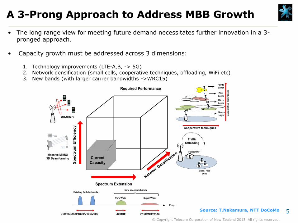
• The long range view for meeting future demand necessitates further innovation in a 3-pronged approach.
• Capacity growth must be addressed across 3 dimensions:
1. Technology improvements (LTE-A,B, -> 5G) 2. Network densification (small cells, cooperative techniques, offloading, WiFi etc) 3. New bands (with larger carrier bandwidths ->WRC15)
Source: T.Nakamura, NTT DoCoMo
Required Performance
Spectrum Extension
Network
Densifi
cation
Sp
ec
tru
m E
ffic
ien
cy
Femto/WiFi
Micro, Pico
cells
Traffic
Offloading
Current
Capacity
MU-MIMO
Massive MIMO/
3D Beamforming
Very Wide Super Wide
Existing Cellular bands
Freq.
New spectrum bands
>100MHz wide40MHz700/850/900/1800/2100/2600
Femto
Layer
Pico
Layer
Micro
Layer
Macro
Layer
Cooperative techniques
Co
op
era
tiv
e t
ec
hn
iqu
es

6
© Copyright Telecom Corporation of New Zealand 2013. All rights reserved.
Layers within the Hierarchy
Macrocell
(~40W @700/850MHz)
Microcell
(~2W @1800MHz)
Picocell, Femtocell,
WiFi AP (~200mW
@>2.6GHz))
Device 2
Device
(~10mW)
Non-cellular
access (e.g WiFi)
Cellular access
(e.g GSM, UMTS,
LTE)
Inc
rea
sin
g C
ov
era
ge
Fo
otp
rin
t o
f C
ell
Co
ve
rag
e L
ay
er
Ca
pa
cit
y L
ay
er
• The future mobile landscape will be Multi-Tiered in the RAN, commonly referred to as Heterogeneous
Network (or HetNet)
• The HetNet paradigm will extend beyond a macro and a single small cell layer, encompassing both licensed,
and unlicensed band technologies as shown below.
• Behind the scene of this landscape will be effective cooperative and mobility robustness mechanisms to
enhance system capacity and offloading capability.
7
© Copyright Telecom Corporation of New Zealand 2013. All rights reserved.
Radio Access Network Topics

8
© Copyright Telecom Corporation of New Zealand 2013. All rights reserved.
HetNet Enabler: eICIC and CRE
• eICIC uses a concept called “Almost Blank Subframe” - a time domain technique that reduces cell edge interference between a macro and pico node in co-channel deployments.
•Cell Range Extension allows the pcio to reach into the macro cell’s “exclusion zone”.
•Research suggests best offload performance occurs when ABS and CRE are used together.
Pico UE
Macro UE
X2_LOAD_INFORMATION [ABS PATTERN]
Exclusion zone inside the macro coverage region
RE
regionPico coverage
with 0dB bias
Power
[dBm]
46
30
Subframe (ms)
Subframe (ms)
CRS interference
ABS Muting
(X dBm)
Protected subframe
that pico schedules UE
in RE region
Protected subframe
that pico schedules
UE in RE region
4 8 12
4 8 12
0 0 0 1 1 1 1 0 0 0
Subframe bit
0=Not ABS
1= ABS
20 bit pattern corresponding to 2 radio frames over 20msSubframe
No.1 2 3 4 5 6 7 8 9 10
Macro cell
Pico cell
Ref: IEEE Wireless Comms, Feb 2013, “Multicell Cooperation for LTE-A HetNet Network Scenario’s”, B.Soret et al

9
© Copyright Telecom Corporation of New Zealand 2013. All rights reserved.
HetNet Enabler: New Carrier Type (NCT)
Phantom Cell
Users control signalling is
sent over the macro cell.
Mobility is achieved thru
anchoring on macrocell
User data is sent over
Phantom cell
Macro
eNodeB
• NCT for the Downlink is a new concept being discussed in 3GPP Rel12.
• NCT is a stripped down (or lean) version of current cells with minimum common control channel overhead.
• Therefore it is not detectable to a device – i.e. UE must be directed by the macro cell.
• The key advantage in this scheme is related to the reduction in interference that would otherwise be generated through Reference Signal and other common channel transmissions (co-channel deployments)
• The macro layer is used as an anchor for vital control and mobility procedures and hence the UE is dual connected.
• Results show that use of NCT can boost 5th-percentile rates upto 70% over Rel8 Legacy Carrier Type operation under low loads and 20% under high loads*
* IEEE Comms Magazine, Feb 2013, “A Lean carrier for LTE”, Hoymann et al

10
© Copyright Telecom Corporation of New Zealand 2013. All rights reserved.
HetNet Enabler: Cooperative Communications
• As we saw in the introduction, simply building out LTE capacity with conventional interference mitigation
approaches (eg. Down tilting, power control etc) will lead to sub-optimal system capacity and over
investment in CAPEX.
• Cell edge, where the bulk of users lie, needs to be the focus of cooperative techniques to lift SINR and
hence capacity.
• Many cooperative schemes have been developed. These schemes allow multiple base stations to
formulate a cooperative cluster, and either coordinate to avoid interference or coordinate to
constructively exploit interference.
• In 3GPP Release 10 and 11 these have been referred to as CoMP, categorised into three types:
1. Coordinated Scheduling (e.g. (e)ICIC) – a cooperating cluster agree which resources
experience the most interference and hence derive partial reuse on such resources. This can
be achieved with preconfigured fractional (or soft) reuse schemes or determined on a dynamic
basis through exchanging interference reports over the X2 link.
2. Coordinated Beamforming – the cooperating cluster shares CSI info for cell edge users such
that each eNodeB can determine precoding matrices that will ensure beams concentrate
energy only to the desired UE. The CSI exchange is done via the X2 link.
3. Joint Processing – the cooperating cluster acts as a virtual antenna array, whereby multiple
sites transmit to the UE simultaneously. Constructively using transmissions which would
otherwise be considered as interference. This scheme requires CSI and user data to be
present at every member of the cluster. X2 is used to facilitate this info exchange.

11
© Copyright Telecom Corporation of New Zealand 2013. All rights reserved.
HetNet Enabler: Cooperative Communications
• The largest gains come from the JP category of CoMP schemes. In Foschini’s paper, gains of upto 300%
(using ER-ZF-CCT for 4x4MIMO) where shown for the MU-MIMO based JP scheme.
• However in practice, 3GPP simulations show only modest gains of 20~30%.
X2
eNodeB
Region of
reuse=1
Region of
reuse=1/3
X2
eNodeB
X2
eNodeB
(a) Coordinated Scheduling
(b) Coordinated Beamforming
(c) Joint Processing
UE
Ref: IEEE Comms Magazine, Aug2013, Biermann et al, and Wireless Comms, G.J Foschini, “Coordinating multiple antenna cellular networks to achieve enormous spectral efficiency”
ER-ZF-CCT: Effective Rate, Zero-Forcing, Coherently Coordinate Transmission
• The major sources that contribute to the
loss in gains are backhaul performance
(<0.5ms RTT), accurate CSI and
quantization errors of CSI (4 bit
encoding), and reference signal collisions.
• Does this mean that we can only
implement CoMP types (a) and (b) in
practical systems? Will that be worth
the investment?
• How can we future proof current
deployments for such cooperative
schemes?

12
© Copyright Telecom Corporation of New Zealand 2013. All rights reserved.
HetNet Enabler: Multi-Flow Aggregation
• NCT and Carrier Aggregation give rise to the concept of “dual connectivity” – i.e being actively attached to 2 or more cells
concurrently.
• This concept is being extended above the PHY and MAC layers (where NCT and CA operate) in capability referred to as
Multi-Flow, which facilitates both capacity and mobility robustness.
• This work is being discussed in 3GPP Rel12. The concept is illustrated below.
Ref: 3GPP TR36.842, “Study on Small Cell Enhancements – Higher Layer Aspects”
MME SGW
PGW
S11
S5
HSS
S6a
Aggregation
Router
X2 VRF
S1 VRF
S1-US1-C
Macro eNodeB
(PCell)
Pico eNodeB 1
(SCell)
f1
f2 f2X2
X2X2
GTP-U
UDP
IP
ETH
Payload:
IP datagram
PDCP
RLC
MAC
PHY
PDSCHPDSCH
PDCCH
UE
Pico eNodeB 2
(SCell)
RLC
MAC
PHY
RLC
MAC
PHY
MME SGW
PGW
S11
S5
HSS
S6a
Aggregation
Router
X2 VRF
S1 VRF
S1-US1-C
Macro eNodeB
(PCell)
Pico eNodeB 1
(SCell)
f1
f2 f2X2
X2X2
GTP-U
UDP
IP
ETH
Payload:
IP datagram
PDCP
RLC
MAC
PHY
UE
Pico eNodeB 2
(SCell)
PDSCH
RLC
MAC
PHY
RLC
MAC
PHY
UE moves out
of PeNB1 and
into PeNB2
PDSCH
PDCCH

13
© Copyright Telecom Corporation of New Zealand 2013. All rights reserved.
Core Network Topics

14
© Copyright Telecom Corporation of New Zealand 2013. All rights reserved.
HetNet Enabler: IP Flow Mobility (IFOM)
• Through the adoption of Mobile IP based
protocols, 3GPP paved the way for non-
cellular access networks like WiFi, WiMAX
etc to be integrated to the EPC.
• The integration of WiFi to the EPC, allows
the addition of WiFi Access Points as
members of the small cell layer.
LTE WiFi
LTE WLAN Access
Network
VoLTE FTP
Flow 2: Traffic
steered via WLAN
LTE Access
Network
Smartphone with
DSMIPv6 support
Evolved Packet
Core
Flow 1: Traffic
steered via LTE
• IP Flow Mobility (IFOM) was standardised in 3GPP Release 10 (TS23.261) .
• IFOM allows the network to steer traffic across LTE and WiFi access based on traffic policies
which can be pushed to the device.
• The device is then able to maintain concurrent flows, move flows between the access types,
or combine flows into a single flow.
• The capability is based on Dual Stack Mobile IPv6 (or DSMIPv6).
15
© Copyright Telecom Corporation of New Zealand 2013. All rights reserved.
A Closer Look at Flow Mobility
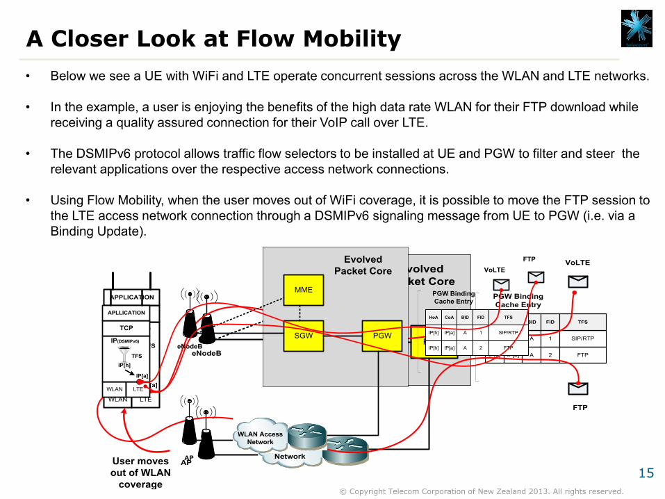
• Below we see a UE with WiFi and LTE operate concurrent sessions across the WLAN and LTE networks.
• In the example, a user is enjoying the benefits of the high data rate WLAN for their FTP download while
receiving a quality assured connection for their VoIP call over LTE.
• The DSMIPv6 protocol allows traffic flow selectors to be installed at UE and PGW to filter and steer the
relevant applications over the respective access network connections.
• Using Flow Mobility, when the user moves out of WiFi coverage, it is possible to move the FTP session to
the LTE access network connection through a DSMIPv6 signaling message from UE to PGW (i.e. via a
Binding Update).
MME
WLAN Access
Network
SGW PGW
WLAN LTE
TCP
APPLICATION
AP
eNodeB
IP[a]IP[b]
TFS
IP (DSMIPv6)
IP[h] IP[a] A 1 SIP/RTP
IP[h] IP[b] A 2 FTP
HoA CoA BID FID TFS
PGW Binding
Cache Entry
IP[h]
VoLTE
FTP
Evolved
Packet Core
MME
WLAN Access
Network
SGW PGW
WLAN LTE
TCP
APLLICATION
AP
eNodeB
IP[a]
IP(DSMIPv6)
IP[h] IP[a] A 1 SIP/RTP
IP[h] IP[a] A 2 FTP
HoA CoA BID FID TFS
PGW Binding
Cache Entry
User moves
out of WLAN
coverage
IP[h]
VoLTE
FTP
TFS
Evolved
Packet Core

16
© Copyright Telecom Corporation of New Zealand 2013. All rights reserved.
SDN in Mobile Networks – a New Functional Architecture
• When we apply SDN concepts to the mobile and transport domains we arrive at the functional architecture depicted below. Two new entities are shown, namely the Mobile Forwarding Entity (M-FE) and Mobile Controller (M-CE) Entity.
UE
S1-C
SDN Transport Domain
SDN Evolved Packet SystemControl Plane
User Plane
Legacy eNodeB
S1-U
Legacy MME
Legacy SGW
Legacy PGW
S3, S10,S11
S11, S5,S8,S4
S5, S8, S2, Gx, Gy
RF INTF Mobile FE
CONTROL INTF
CONTROL INTF
MME SGW PGW
PCRF GGSN CSCF
SGSN SaMOG HSS
MOCN ANDSFCoMP
CONTROL INTF
MPLS BGP L2TP
DPI GGSN CSCF
BNG etcAAA
Mobile FE
CONTROL INTF
Transport FE
CONTROL INTF
Transport FE
CONTROL INTF
E.g. OpenFlow
M-FE M-FE
M-CE
Ref: IEEE Comms Magazine, July 2013, “Mobile Flow: Toward SDN in Mobile Networks”, K.Pentikousis et al

17
© Copyright Telecom Corporation of New Zealand 2013. All rights reserved.
SDN in Mobile Networks – Applied View #2 Local Breakout
UE
SDN Transport
Domain
SDN Evolved Packet System Control Plane
User Plane
RF INTF
CONTROL INTF
MPLS LDP BGP
E.g. OpenFlow
CONTROL INTF
MME SGW PGW
GTP-U
S1AP
GTP-U
GTP-C
GTP-U
eNodeB, SGW, PGW FE
Control Intf
S1-C
S1-U
S11, S5-C
S5-UUDP/
IP/Eth
LDP/PW
CW
MPLS/
Eth
Control Intf
CE Node
CDN Server
PDN
User plane
Packet
LDP/PW
CW
MPLS/
Eth
Control Intf
IP/EthIP/Eth
M-FE
M-CE

18
© Copyright Telecom Corporation of New Zealand 2013. All rights reserved.
Distributed Mobility Management (DMM)
APN1:HoA_A
eNodeB
SGW/PGW
A
MME AAA HSS
LMA/MAG
A
AP
SGW/PGW
B
LMA/MAG
B
Internet
S11,S1-C,S5-C
HoA_A
CoA_A
HoA_B
CoA_B
MovementMovement
APN2:HoA_B
CN_2CN_1
New binding cache entry
added to PGW A after UE
moves to PGW B:
HoA_A -> HoA_B
LTE:
GTP Solution
WiFi:
PMIPv6 Solution
S6a
SWx
S1
Mobile SDN
Controller
New binding cache entry
added to LMA A after UE
moves to LMA B:
HoA_A -> HoA_B
GTP-U
TunnelIPv6-in-IPv6
Tunnel
UE
SWm
• In EPS, mobility management is based on either GTP or derivatives of MobileIP (DSMIPv6, PMIPv6, MIPv4 or v6). These are based on a centralised anchor point, which must remain the same for session continuity.
• DMM moves the control and user plane mobility anchor points closer to the edge and allows the UE to move between mobility anchors while still maintaining session continuity.
• DMM solutions are classified as either a) client-based b) network based (with full or partial distribution) or c) routing based.
Ref: IEEE Comms Magazine, March 2013, “Distributed Mobility Management: A Standards Landscape, J. Zuniga et al

19
© Copyright Telecom Corporation of New Zealand 2013. All rights reserved.
The Long Term View of EPS

20
© Copyright Telecom Corporation of New Zealand 2013. All rights reserved.
Long Term Multi-Tier Landscape
• Putting it all together….
Coverage Layer
(macro layer)
eNB
WiFi AP
Capacity Layer
(Indoors)
Capacity Layer
(Outdoors)eNodeB
eNB
WiFi AP
eNB
Control Intf
S1AP
CONTROL INTF
MME SaMOG S/PGW-C
Centralised Data Centre for
Control Plane
SDN
MC
Distributed
M-FE
Capacity Layer
(Indoors)
(e)ICIC
eICIC
(e)ICIC
UE
CA + IFOM +
Multi-Flow
User
Plane
PDN
CDN
Internet
application
SaMOG/
SGW/
PGW
Distributed
M-FE
S1
S1
X2 X2
X2
CoMP Beamforming
CoMP Beamfo
rming
Tn
Recommended