1
2007 Structures Congress May 172007 Structures Congress May 17--19 Long Beach CA19 Long Beach CA TD12 TD12 -- 11
Evaluation and Modification Evaluation and Modification of Openof Open--Web Steel Joists and Web Steel Joists and
Joist GirdersJoist Girders
Perry S. Green, Ph.D., Technical DirectorSteel Joist InstituteMyrtle Beach, SC
2007 Structures Congress May 172007 Structures Congress May 17--19 Long Beach CA19 Long Beach CA TD12 TD12 -- 22
IntroductionIntroduction
Commercial manufacture of open web steel joists began in 1923The Steel Joist Institute was formed in 1928• Steel joist use has continued to grow• There are millions of joists in service
2
2007 Structures Congress May 172007 Structures Congress May 17--19 Long Beach CA19 Long Beach CA TD12 TD12 -- 33
Introduction (contIntroduction (cont’’d)d)
Evaluation and Modification of joists are required for many reasons:
Building renovationsAddition of roof top unitsConveyor loadsField deviationsOther changes not contemplated in the original design
2007 Structures Congress May 172007 Structures Congress May 17--19 Long Beach CA19 Long Beach CA TD12 TD12 -- 44
New Resource AvailableNew Resource Available
SJI Technical Digest No. 12Evaluation and Modification of Open-
Web Steel Joists and Joist Girders
Present proceduresSuggest details for modification or strengthening
3
2007 Structures Congress May 172007 Structures Congress May 17--19 Long Beach CA19 Long Beach CA TD12 TD12 -- 55
SJI Technical Digest No. 12SJI Technical Digest No. 12BACKGROUNDGLOSSARYChapter 1 EVALUATIONS OF EXISTING JOIST STRENGTHChapter 2 METHODS OF SUPPORTING ADDITIONAL LOADChapter 3 DESIGN APPROACHES FOR STRENGTHENING
JOISTSChapter 4 DESIGN APPROACHES FOR MODIFYING
JOISTS- SHORTENING AND LENGTHENINGChapter 5 OTHER CONSIDERATIONSChapter 6 SUMMARYREFERENCESAPPENDIX A JOIST INVESTIGATION FORMAPPENDIX B COMMON PROPERTIES OF EQUAL LEG
ANGLES WITH LEG SIZES 2 IN. OR LESS
2007 Structures Congress May 172007 Structures Congress May 17--19 Long Beach CA19 Long Beach CA TD12 TD12 -- 66
Glossary of TermsGlossary of TermsAllowable Strength Design (ASD)Allowable StrengthAvailable StrengthBearingBridgingBucklingBuckling StrengthCamberChordsCold-Formed Steel Structural MemberComposite Section
ConnectionDeckDesign LoadDesign StrengthEnd Diagonal or WebEnd WeldsExisting MemberFillerJointJoistJoist Girder
4
2007 Structures Congress May 172007 Structures Congress May 17--19 Long Beach CA19 Long Beach CA TD12 TD12 -- 77
Glossary of TermsGlossary of Terms
LoadLRFD (Load and Resistance Factor Design)MaterialNominal StrengthPreload ForceReinforcing MemberRequired StrengthResistance Factor, ΦSafety Factor, ΩSlenderness RatioSpan
Specified Minimum Yield StressSpecifying ProfessionalSpliceStabilityStandard SpecificationsStructural AnalysisTagged EndWebsYield PointYield StrengthYield Stress
2007 Structures Congress May 172007 Structures Congress May 17--19 Long Beach CA19 Long Beach CA TD12 TD12 -- 88
Chapter 1Chapter 1 Evaluation of Existing Evaluation of Existing Joist StrengthJoist Strength
Determine Capacity of Existing Joist System
As-built design of joistsExisting joists possibly over specifiedBuilding usage may have changedHave joists been damaged

5
2007 Structures Congress May 172007 Structures Congress May 17--19 Long Beach CA19 Long Beach CA TD12 TD12 -- 99
As As -- Built Design of JoistsBuilt Design of Joists
How to Determine
Original contract structural documentsFinal joist erection drawingsYear job was constructedJoist manufacturers identification tagField investigation and measurements
2007 Structures Congress May 172007 Structures Congress May 17--19 Long Beach CA19 Long Beach CA TD12 TD12 -- 1010
Joist DrawingsJoist DrawingsStructural Drawing
DesignationJoist Spacing
Erection DrawingDesignationJoist SpacingMark Number
6
2007 Structures Congress May 172007 Structures Congress May 17--19 Long Beach CA19 Long Beach CA TD12 TD12 -- 1111
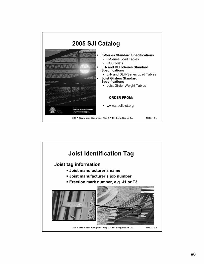
2005 SJI Catalog2005 SJI Catalog
K-Series Standard Specifications• K-Series Load Tables• KCS Joists
LH- and DLH-Series Standard Specifications• LH- and DLH-Series Load Tables
Joist Girders Standard Specifications• Joist Girder Weight Tables
ORDER FROM:
• www.steeljoist.org
2007 Structures Congress May 172007 Structures Congress May 17--19 Long Beach CA19 Long Beach CA TD12 TD12 -- 1212
Joist tag informationJoist manufacturer’s nameJoist manufacturer’s job numberErection mark number, e.g. J1 or T3
Joist Identification TagJoist Identification Tag
7
2007 Structures Congress May 172007 Structures Congress May 17--19 Long Beach CA19 Long Beach CA TD12 TD12 -- 1313
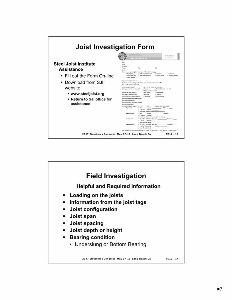
Joist Investigation FormJoist Investigation Form
Steel Joist Institute Assistance
Fill out the Form On-lineDownload from SJI website
www.steeljoist.orgReturn to SJI office for assistance
2007 Structures Congress May 172007 Structures Congress May 17--19 Long Beach CA19 Long Beach CA TD12 TD12 -- 1414
Field InvestigationField InvestigationHelpful and Required Information
Loading on the joistsInformation from the joist tagsJoist configurationJoist spanJoist spacingJoist depth or heightBearing condition• Underslung or Bottom Bearing
8
2007 Structures Congress May 172007 Structures Congress May 17--19 Long Beach CA19 Long Beach CA TD12 TD12 -- 1515
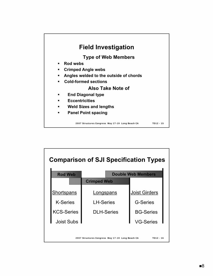
Field InvestigationField InvestigationType of Web Members
Rod websCrimped Angle websAngles welded to the outside of chordsCold-formed sections
Also Take Note ofEnd Diagonal typeEccentricitiesWeld Sizes and lengthsPanel Point spacing
2007 Structures Congress May 172007 Structures Congress May 17--19 Long Beach CA19 Long Beach CA TD12 TD12 -- 1616
Comparison of SJI Specification TypesComparison of SJI Specification Types
Shortspans
K-Series
KCS-Series
Joist Subs
Longspans
LH-Series
DLH-Series
Joist Girders
G-Series
BG-Series
VG-Series
Rod WebCrimped Web
Double Web Members
9
2007 Structures Congress May 172007 Structures Congress May 17--19 Long Beach CA19 Long Beach CA TD12 TD12 -- 1717
Field InvestigationField Investigation
Type of Chord Members
Double Angles• Separation distance• Fillers or tiesCold-formed sectionsRodsSplices
2007 Structures Congress May 172007 Structures Congress May 17--19 Long Beach CA19 Long Beach CA TD12 TD12 -- 1818
Field InvestigationField Investigation
Other Items to Note
Type of Bridging and LocationsQuality of bridging connectionsAnchorage of bridgingInterferencesCoupon samples to determine yield strengthCondition of joists and existing deck
10
2007 Structures Congress May 172007 Structures Congress May 17--19 Long Beach CA19 Long Beach CA TD12 TD12 -- 1919
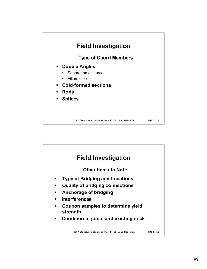
Joist Chord Damage During HandlingJoist Chord Damage During Handling
2007 Structures Congress May 172007 Structures Congress May 17--19 Long Beach CA19 Long Beach CA TD12 TD12 -- 2020
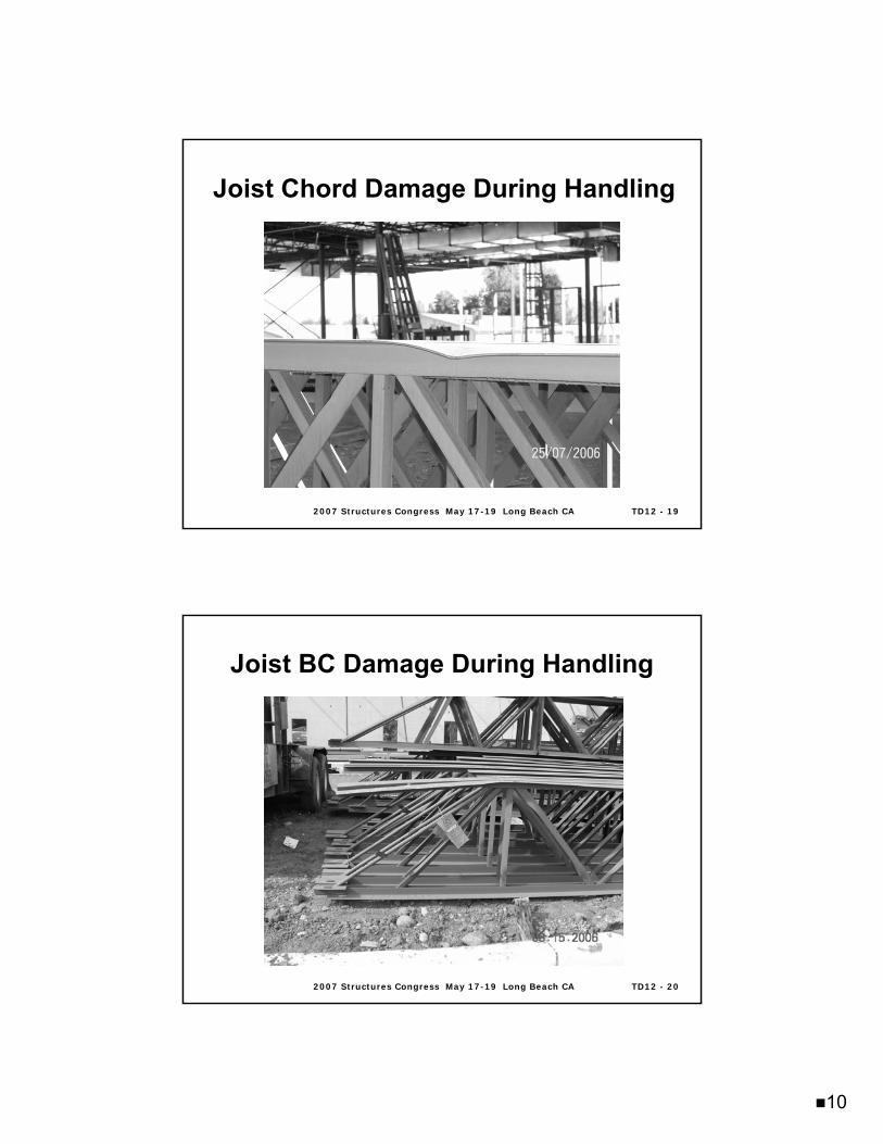
Joist BC Damage During HandlingJoist BC Damage During Handling
11
2007 Structures Congress May 172007 Structures Congress May 17--19 Long Beach CA19 Long Beach CA TD12 TD12 -- 2121
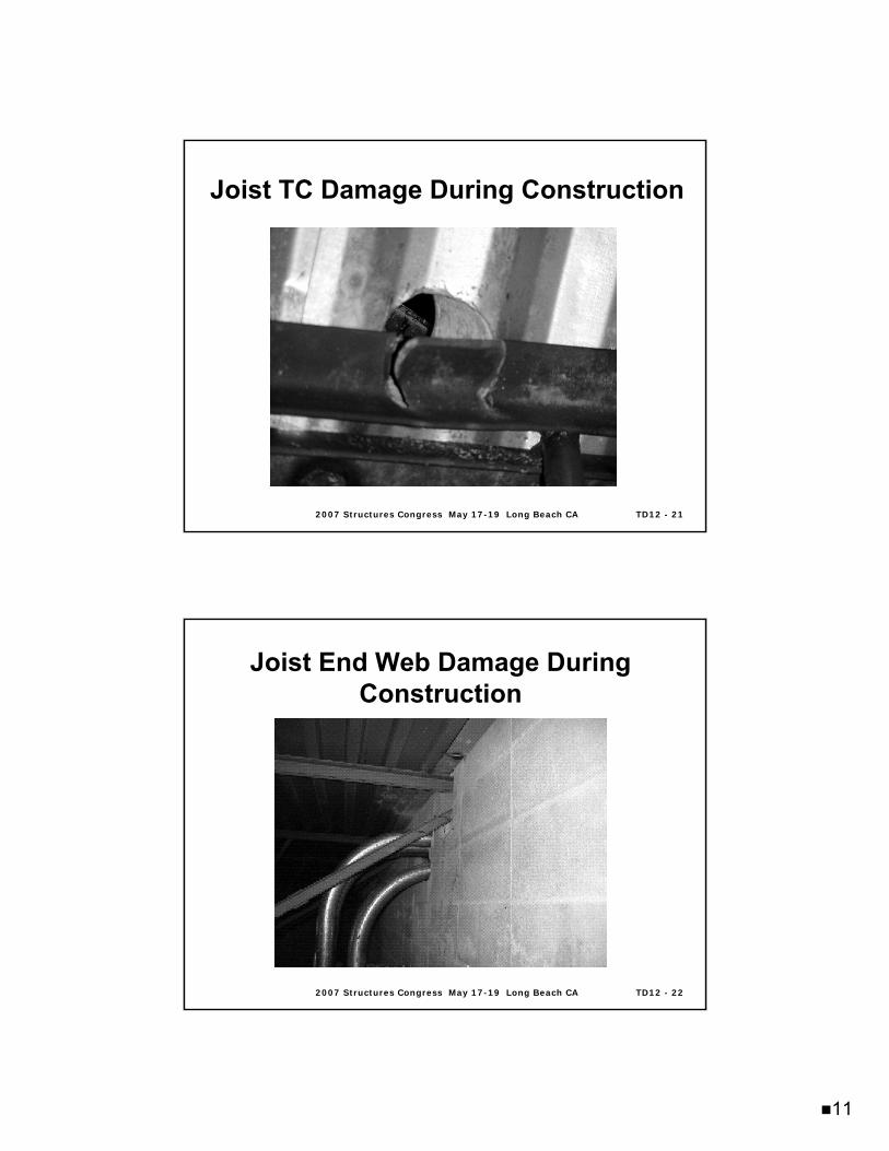
Joist TC Damage During ConstructionJoist TC Damage During Construction
2007 Structures Congress May 172007 Structures Congress May 17--19 Long Beach CA19 Long Beach CA TD12 TD12 -- 2222
Joist End Web Damage During Joist End Web Damage During ConstructionConstruction
12
2007 Structures Congress May 172007 Structures Congress May 17--19 Long Beach CA19 Long Beach CA TD12 TD12 -- 2323
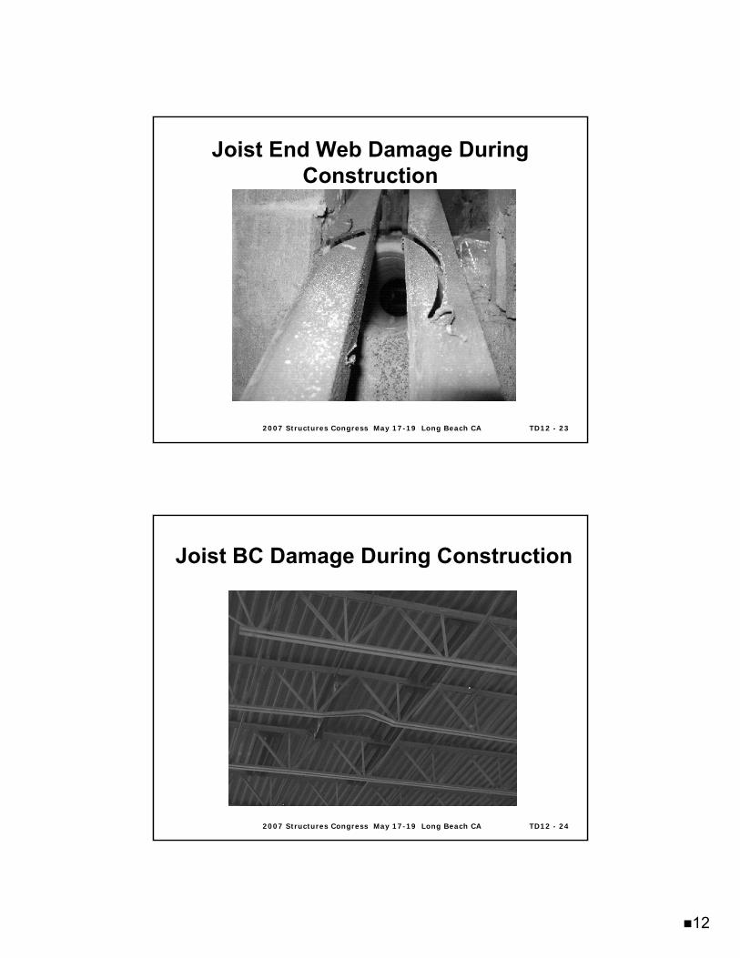
Joist End Web Damage During Joist End Web Damage During ConstructionConstruction
2007 Structures Congress May 172007 Structures Congress May 17--19 Long Beach CA19 Long Beach CA TD12 TD12 -- 2424
Joist BC Damage During ConstructionJoist BC Damage During Construction
13
2007 Structures Congress May 172007 Structures Congress May 17--19 Long Beach CA19 Long Beach CA TD12 TD12 -- 2525
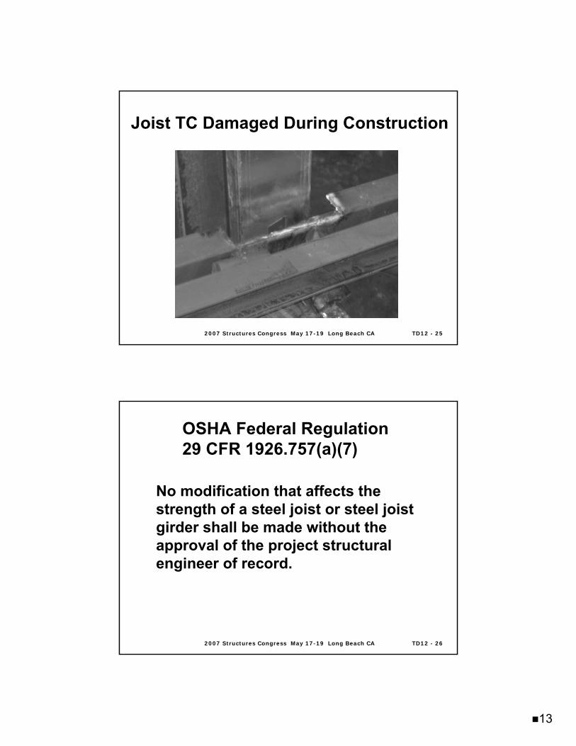
Joist TC Damaged During ConstructionJoist TC Damaged During Construction
2007 Structures Congress May 172007 Structures Congress May 17--19 Long Beach CA19 Long Beach CA TD12 TD12 -- 2626
OSHA Federal Regulation OSHA Federal Regulation 29 CFR 1926.757(a)(7)29 CFR 1926.757(a)(7)
No modification that affects the strength of a steel joist or steel joist girder shall be made without the approval of the project structural engineer of record.
14
2007 Structures Congress May 172007 Structures Congress May 17--19 Long Beach CA19 Long Beach CA TD12 TD12 -- 2727
To Analyze Joist CapacityPinned connections are assumed for web membersSpecifications for K-Series joists permit bending to be neglected when
• Panel point spacing does not exceed 24 inches• The applied loads are uniform
A first-order analysis is usedThe SJI permits eccentricities to be neglected when
• For K-Series, the “3/4 Rule” is followed• For all other joist series, when the eccentricity
“… does not exceed the distance between the centroid and back of the chord”
Analysis ConsiderationsAnalysis Considerations
2007 Structures Congress May 172007 Structures Congress May 17--19 Long Beach CA19 Long Beach CA TD12 TD12 -- 2828
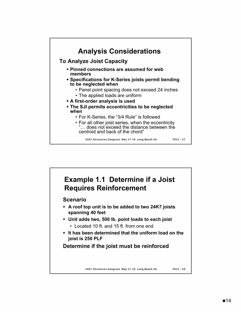
Example 1.1 Determine if a Joist Example 1.1 Determine if a Joist Requires ReinforcementRequires Reinforcement
ScenarioA roof top unit is to be added to two 24K7 joists spanning 40 feetUnit adds two, 500 lb. point loads to each joist• Located 10 ft. and 15 ft. from one end
It has been determined that the uniform load on the joist is 250 PLF
Determine if the joist must be reinforced
15
2007 Structures Congress May 172007 Structures Congress May 17--19 Long Beach CA19 Long Beach CA TD12 TD12 -- 2929
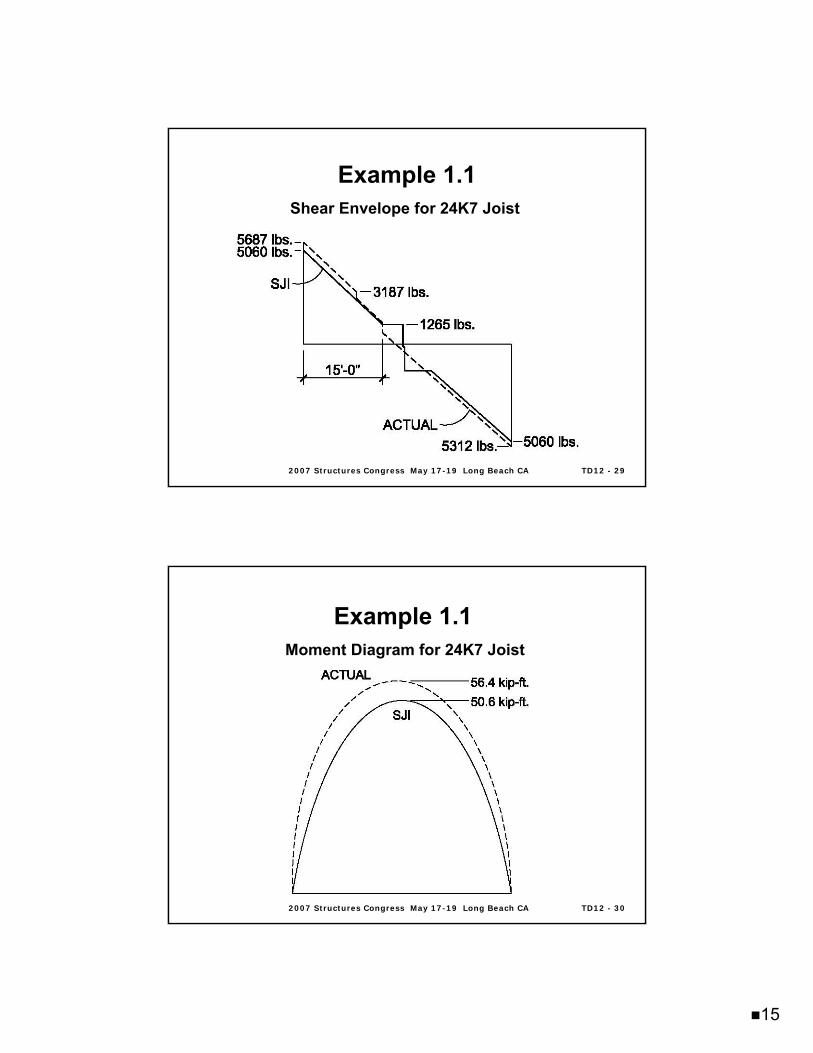
Example 1.1Example 1.1Shear Envelope for 24K7 Joist
2007 Structures Congress May 172007 Structures Congress May 17--19 Long Beach CA19 Long Beach CA TD12 TD12 -- 3030
Example 1.1Example 1.1Moment Diagram for 24K7 Joist
16
2007 Structures Congress May 172007 Structures Congress May 17--19 Long Beach CA19 Long Beach CA TD12 TD12 -- 3131
Chapter 2Chapter 2 Methods of Supporting Methods of Supporting Additional LoadAdditional Load
Options Before Strengthening
Capacity of joist needs to be determined• Can joist safely support new loads?Extensive reinforcement may not be practical• Option #1- Load distribution• Option #2- Add new joists or beams• Reinforce existing joists
2007 Structures Congress May 172007 Structures Congress May 17--19 Long Beach CA19 Long Beach CA TD12 TD12 -- 3232
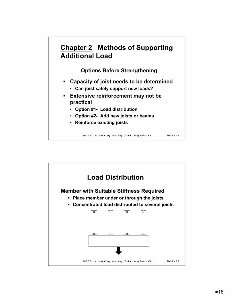
Load DistributionLoad Distribution
Member with Suitable Stiffness RequiredPlace member under or through the joistsConcentrated load distributed to several joists
17
2007 Structures Congress May 172007 Structures Congress May 17--19 Long Beach CA19 Long Beach CA TD12 TD12 -- 3333
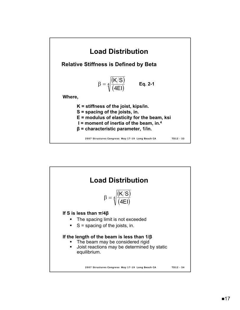
Load DistributionLoad Distribution
Where,
K = stiffness of the joist, kips/in.S = spacing of the joists, in.E = modulus of elasticity for the beam, ksiI = moment of inertia of the beam, in.4β = characteristic parameter, 1/in.
( )( )4
EI4SK
=β
Relative Stiffness is Defined by Beta
Eq. 2-1
2007 Structures Congress May 172007 Structures Congress May 17--19 Long Beach CA19 Long Beach CA TD12 TD12 -- 3434
Load DistributionLoad Distribution
If S is less than π/4βThe spacing limit is not exceededS = spacing of the joists, in.
If the length of the beam is less than 1/βThe beam may be considered rigidJoist reactions may be determined by static equilibrium.
( )( )4
EI4SK
=β
18
2007 Structures Congress May 172007 Structures Congress May 17--19 Long Beach CA19 Long Beach CA TD12 TD12 -- 3535
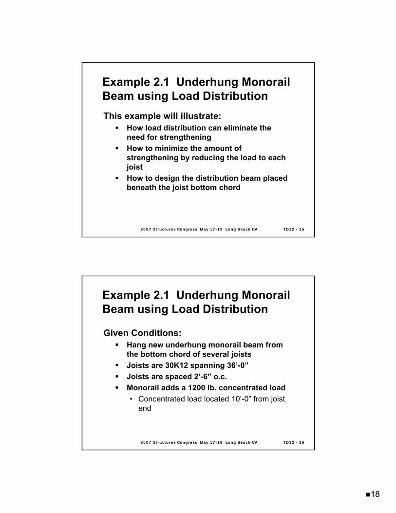
This example will illustrate: How load distribution can eliminate the need for strengtheningHow to minimize the amount of strengthening by reducing the load to each joistHow to design the distribution beam placed beneath the joist bottom chord
Example 2.1 Example 2.1 UnderhungUnderhung Monorail Monorail Beam using Load DistributionBeam using Load Distribution
2007 Structures Congress May 172007 Structures Congress May 17--19 Long Beach CA19 Long Beach CA TD12 TD12 -- 3636
Given Conditions:Hang new underhung monorail beam from the bottom chord of several joistsJoists are 30K12 spanning 36’-0”Joists are spaced 2’-6” o.c.Monorail adds a 1200 lb. concentrated load• Concentrated load located 10’-0” from joist
end
Example 2.1 Example 2.1 UnderhungUnderhung Monorail Monorail Beam using Load DistributionBeam using Load Distribution
19
2007 Structures Congress May 172007 Structures Congress May 17--19 Long Beach CA19 Long Beach CA TD12 TD12 -- 3737
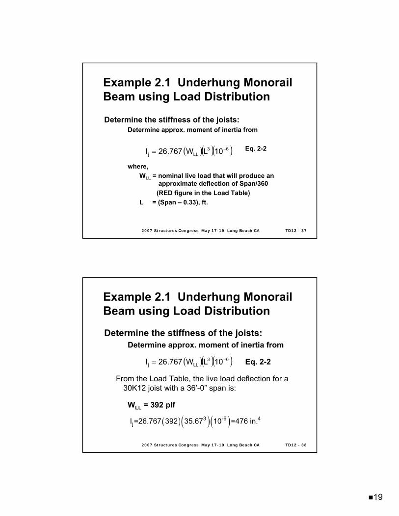
Determine the stiffness of the joists: Determine approx. moment of inertia from
Eq. 2-2
where,WLL = nominal live load that will produce an
approximate deflection of Span/360 (RED figure in the Load Table)
L = (Span – 0.33), ft.
( )( )( )63LLj 10LW767.26I −=
Example 2.1 Example 2.1 UnderhungUnderhung Monorail Monorail Beam using Load DistributionBeam using Load Distribution
2007 Structures Congress May 172007 Structures Congress May 17--19 Long Beach CA19 Long Beach CA TD12 TD12 -- 3838
Determine the stiffness of the joists: Determine approx. moment of inertia from
Eq. 2-2
From the Load Table, the live load deflection for a 30K12 joist with a 36’-0” span is:
WLL = 392 plf
( )( )( )63LLj 10LW767.26I −=
( ) ( ) ( )3 -6 4jI =26.767 392 35.67 10 =476 in.
Example 2.1 Example 2.1 UnderhungUnderhung Monorail Monorail Beam using Load DistributionBeam using Load Distribution
20
2007 Structures Congress May 172007 Structures Congress May 17--19 Long Beach CA19 Long Beach CA TD12 TD12 -- 3939
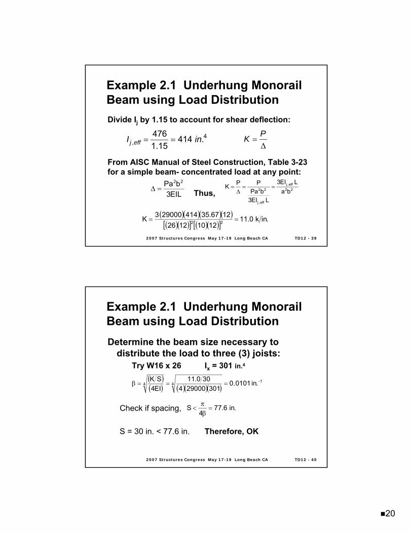
Divide Ij by 1.15 to account for shear deflection:
From AISC Manual of Steel Construction, Table 3-23 for a simple beam- concentrated load at any point:
Thus,
= = 4,
476 414 .1.15j effI in =
∆PK
EIL3bPa 22
=∆ 22eff,j
eff,j
22 baLEI3
LEI3bPa
PPK ==∆
=
( )( )( )( )( )( )[ ] ( )( )[ ]
.ink0.1112101226
1267.35414290003K 22 ==
Example 2.1 Example 2.1 UnderhungUnderhung Monorail Monorail Beam using Load DistributionBeam using Load Distribution
2007 Structures Congress May 172007 Structures Congress May 17--19 Long Beach CA19 Long Beach CA TD12 TD12 -- 4040
Determine the beam size necessary to distribute the load to three (3) joists:
Try W16 x 26 Ix = 301 in.4
Check if spacing,
S = 30 in. < 77.6 in. Therefore, OK
( )( ) ( )( )( )
144 .in0101.0
301290004300.11
EI4SK −===β
.in6.774
S =βπ
<
Example 2.1 Example 2.1 UnderhungUnderhung Monorail Monorail Beam using Load DistributionBeam using Load Distribution
21
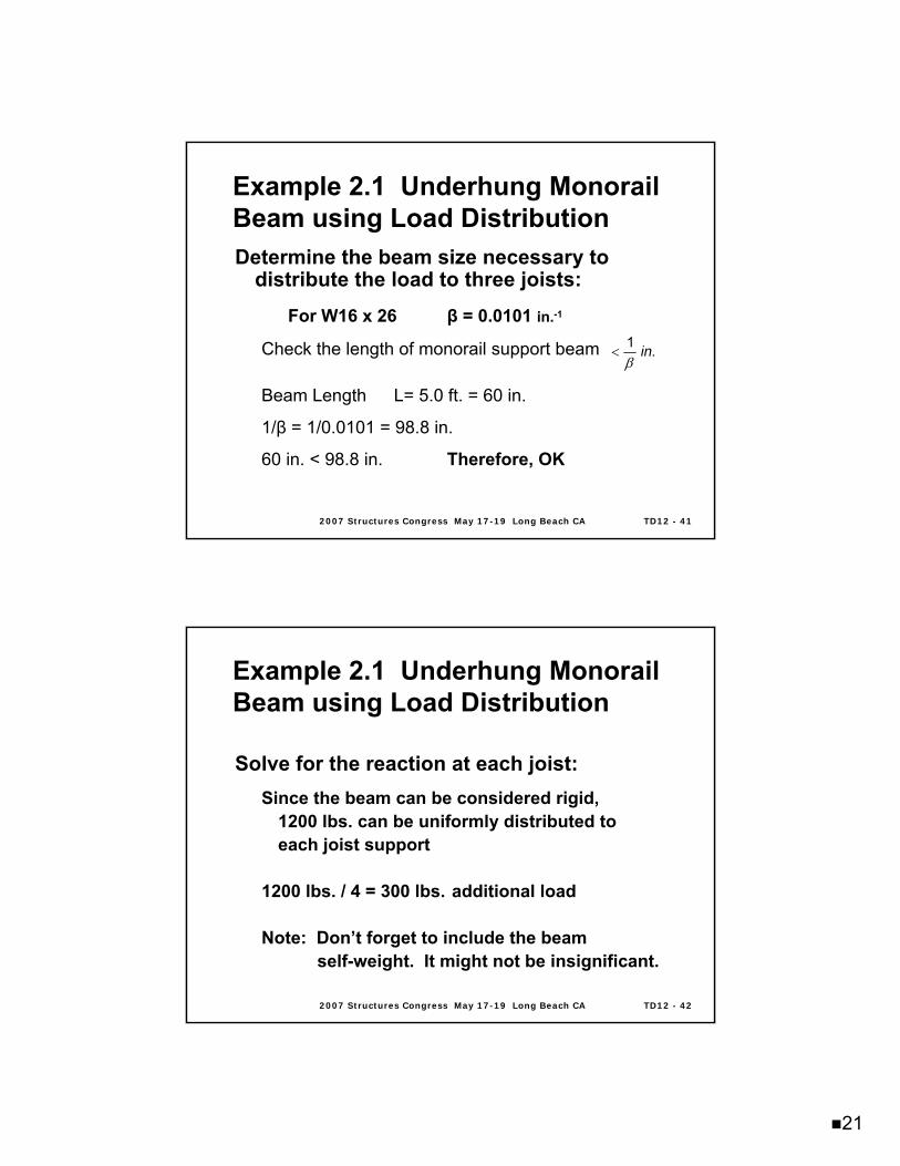
2007 Structures Congress May 172007 Structures Congress May 17--19 Long Beach CA19 Long Beach CA TD12 TD12 -- 4141
Determine the beam size necessary to distribute the load to three joists:
For W16 x 26 β = 0.0101 in.-1
Check the length of monorail support beam
Beam Length L= 5.0 ft. = 60 in.
1/β = 1/0.0101 = 98.8 in.
60 in. < 98.8 in. Therefore, OK
β<
1 .in
Example 2.1 Example 2.1 UnderhungUnderhung Monorail Monorail Beam using Load DistributionBeam using Load Distribution
2007 Structures Congress May 172007 Structures Congress May 17--19 Long Beach CA19 Long Beach CA TD12 TD12 -- 4242
Solve for the reaction at each joist:Since the beam can be considered rigid,
1200 lbs. can be uniformly distributed to each joist support
1200 lbs. / 4 = 300 lbs. additional load
Note: Don’t forget to include the beam self-weight. It might not be insignificant.
Example 2.1 Example 2.1 UnderhungUnderhung Monorail Monorail Beam using Load DistributionBeam using Load Distribution
22
2007 Structures Congress May 172007 Structures Congress May 17--19 Long Beach CA19 Long Beach CA TD12 TD12 -- 4343
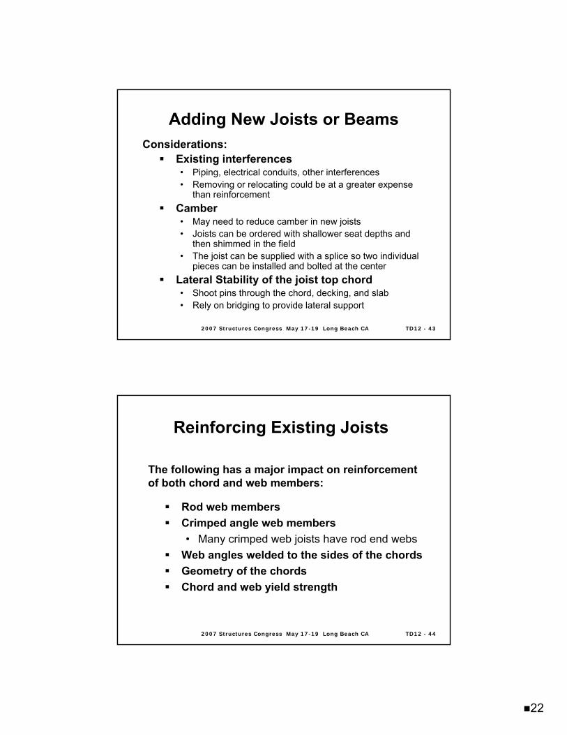
Adding New Joists or BeamsAdding New Joists or BeamsConsiderations:
Existing interferences• Piping, electrical conduits, other interferences• Removing or relocating could be at a greater expense
than reinforcementCamber• May need to reduce camber in new joists• Joists can be ordered with shallower seat depths and
then shimmed in the field• The joist can be supplied with a splice so two individual
pieces can be installed and bolted at the centerLateral Stability of the joist top chord• Shoot pins through the chord, decking, and slab• Rely on bridging to provide lateral support
2007 Structures Congress May 172007 Structures Congress May 17--19 Long Beach CA19 Long Beach CA TD12 TD12 -- 4444
Reinforcing Existing JoistsReinforcing Existing Joists
The following has a major impact on reinforcement of both chord and web members:
Rod web membersCrimped angle web members• Many crimped web joists have rod end webs
Web angles welded to the sides of the chordsGeometry of the chordsChord and web yield strength
23
2007 Structures Congress May 172007 Structures Congress May 17--19 Long Beach CA19 Long Beach CA TD12 TD12 -- 4545
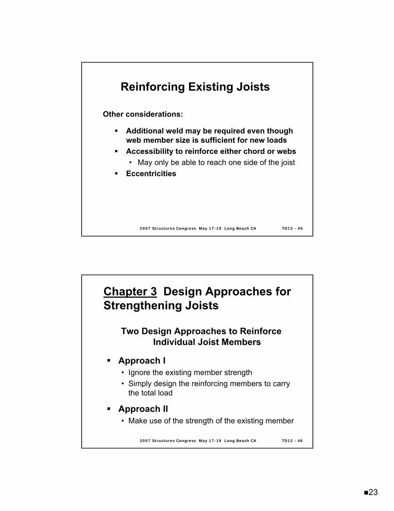
Reinforcing Existing JoistsReinforcing Existing Joists
Other considerations:
Additional weld may be required even though web member size is sufficient for new loadsAccessibility to reinforce either chord or webs• May only be able to reach one side of the joist
Eccentricities
2007 Structures Congress May 172007 Structures Congress May 17--19 Long Beach CA19 Long Beach CA TD12 TD12 -- 4646
Chapter 3Chapter 3 Design Approaches for Design Approaches for Strengthening JoistsStrengthening Joists
Two Design Approaches to Reinforce Individual Joist Members
Approach I• Ignore the existing member strength• Simply design the reinforcing members to carry
the total load
Approach II• Make use of the strength of the existing member
24
2007 Structures Congress May 172007 Structures Congress May 17--19 Long Beach CA19 Long Beach CA TD12 TD12 -- 4747
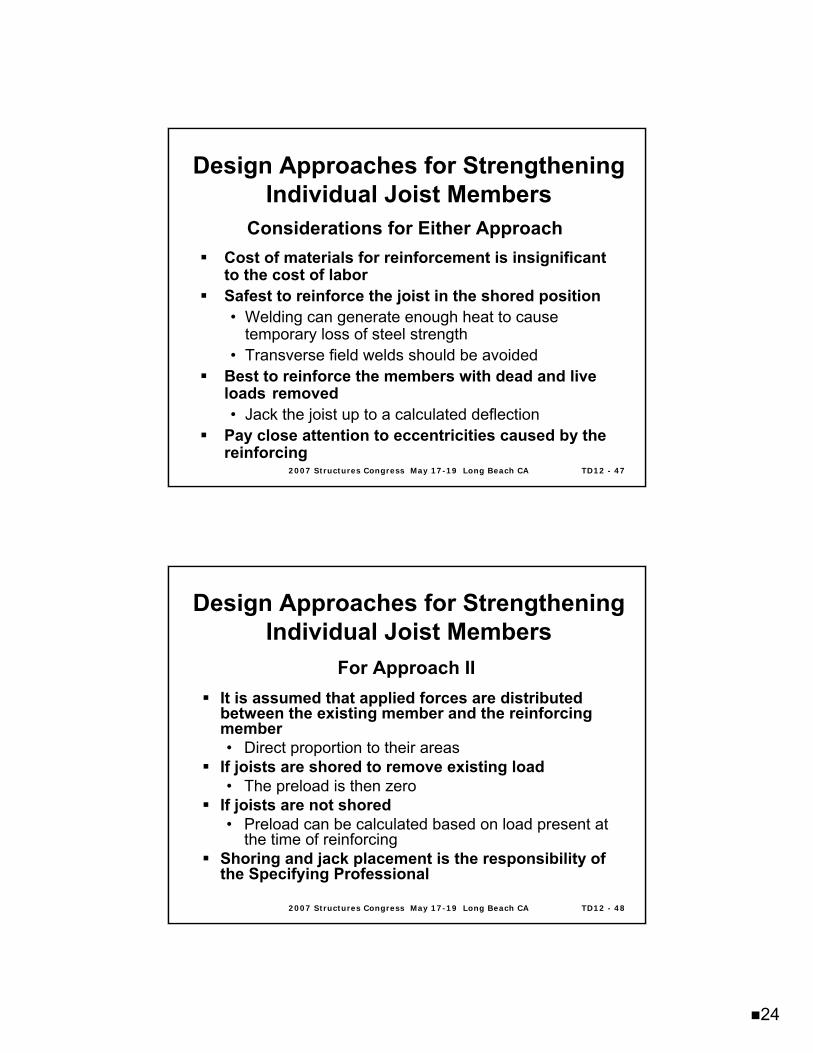
Design Approaches for Strengthening Design Approaches for Strengthening Individual Joist MembersIndividual Joist Members
Considerations for Either ApproachCost of materials for reinforcement is insignificant to the cost of laborSafest to reinforce the joist in the shored position• Welding can generate enough heat to cause
temporary loss of steel strength• Transverse field welds should be avoided
Best to reinforce the members with dead and live loads removed• Jack the joist up to a calculated deflection
Pay close attention to eccentricities caused by the reinforcing
2007 Structures Congress May 172007 Structures Congress May 17--19 Long Beach CA19 Long Beach CA TD12 TD12 -- 4848
Design Approaches for Strengthening Design Approaches for Strengthening Individual Joist MembersIndividual Joist Members
For Approach IIIt is assumed that applied forces are distributed between the existing member and the reinforcing member• Direct proportion to their areas
If joists are shored to remove existing load• The preload is then zero
If joists are not shored• Preload can be calculated based on load present at
the time of reinforcingShoring and jack placement is the responsibility of the Specifying Professional
25
2007 Structures Congress May 172007 Structures Congress May 17--19 Long Beach CA19 Long Beach CA TD12 TD12 -- 4949
Design of Reinforcing for Tension Design of Reinforcing for Tension Members (Approach II)Members (Approach II)
1. Determine the total area required, Atr
Where,Atr = Total area required (existing member and
required reinforcing), in.2Ae = Area of existing member, in.2P0 = Original force for the existing member
(original design force), kips.Pp = Preload in the existing member at the time
of reinforcing, kips.Pt = Required strength, kips.
Assumes existing steel and reinforcing steel both have equal yield strength
( )( ) e
po
pttr A
PPPP
A−−
=
2007 Structures Congress May 172007 Structures Congress May 17--19 Long Beach CA19 Long Beach CA TD12 TD12 -- 5050
Design of Reinforcing for Tension Design of Reinforcing for Tension Members (Approach II)Members (Approach II)
Design procedures when the yield strengths of the two materials are not equal:
Assume both materials have the same yield strength as that of the lowest material used• Most conservative method
Use the actual yield strength of each material in the design• Allow each material to achieve the full allowed
stress level
26
2007 Structures Congress May 172007 Structures Congress May 17--19 Long Beach CA19 Long Beach CA TD12 TD12 -- 5151
Design of Reinforcing for Tension Design of Reinforcing for Tension Members (Approach II)Members (Approach II)
2. Determine required area of reinforcing, Ar
3. The force in the reinforcing member equals
Where,Afr = Area of the furnished reinforcing, in.2At = Area of existing member plus the area of
the furnished reinforcing, in.2
etrr AAA −=
( )ptt
frr PP
AAP −⎟⎟
⎠
⎞⎜⎜⎝
⎛=
2007 Structures Congress May 172007 Structures Congress May 17--19 Long Beach CA19 Long Beach CA TD12 TD12 -- 5252
Design of Reinforcing for Design of Reinforcing for Compression Members (Approach II)Compression Members (Approach II)
1. Select a trial reinforcing member.2. Check the buckling strength of the composite
member.• If a preload force exists, determine the magnitude
of the compressive stress in the existing member due to the preload, fp
• Fye = minimum yield stress of existing member, ksi• For the buckling check, use Fy as the minimum of
(Fye – fp) or Fy3. Design the weld for the reinforcing member. The
force in the weld is( )⎛ ⎞
= −⎜ ⎟⎝ ⎠
frrw t p
t
AP P PA
27
2007 Structures Congress May 172007 Structures Congress May 17--19 Long Beach CA19 Long Beach CA TD12 TD12 -- 5353
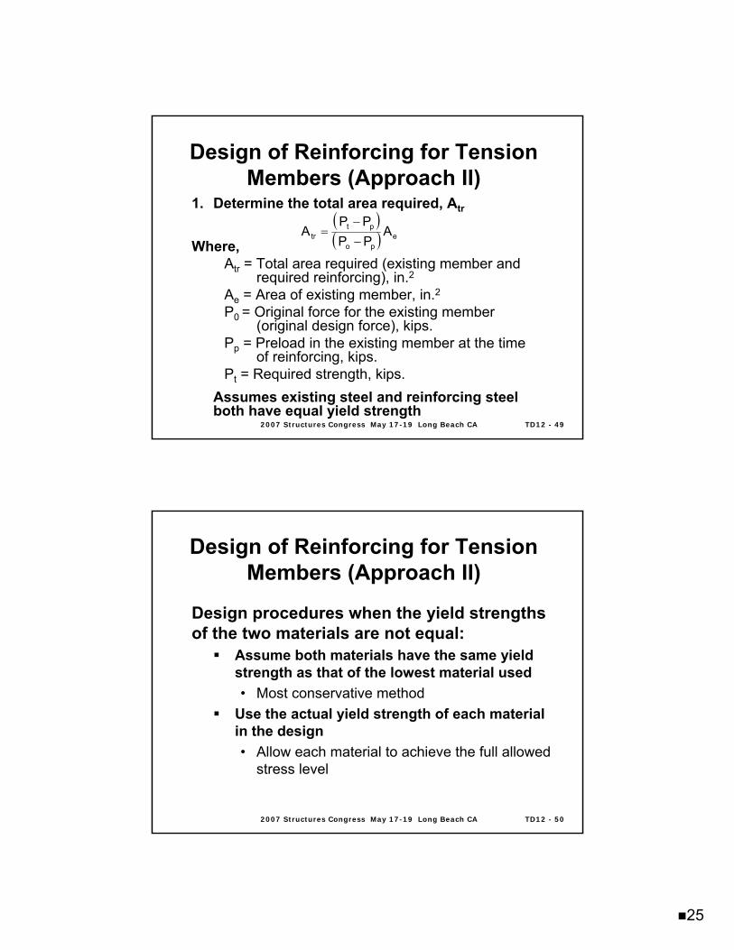
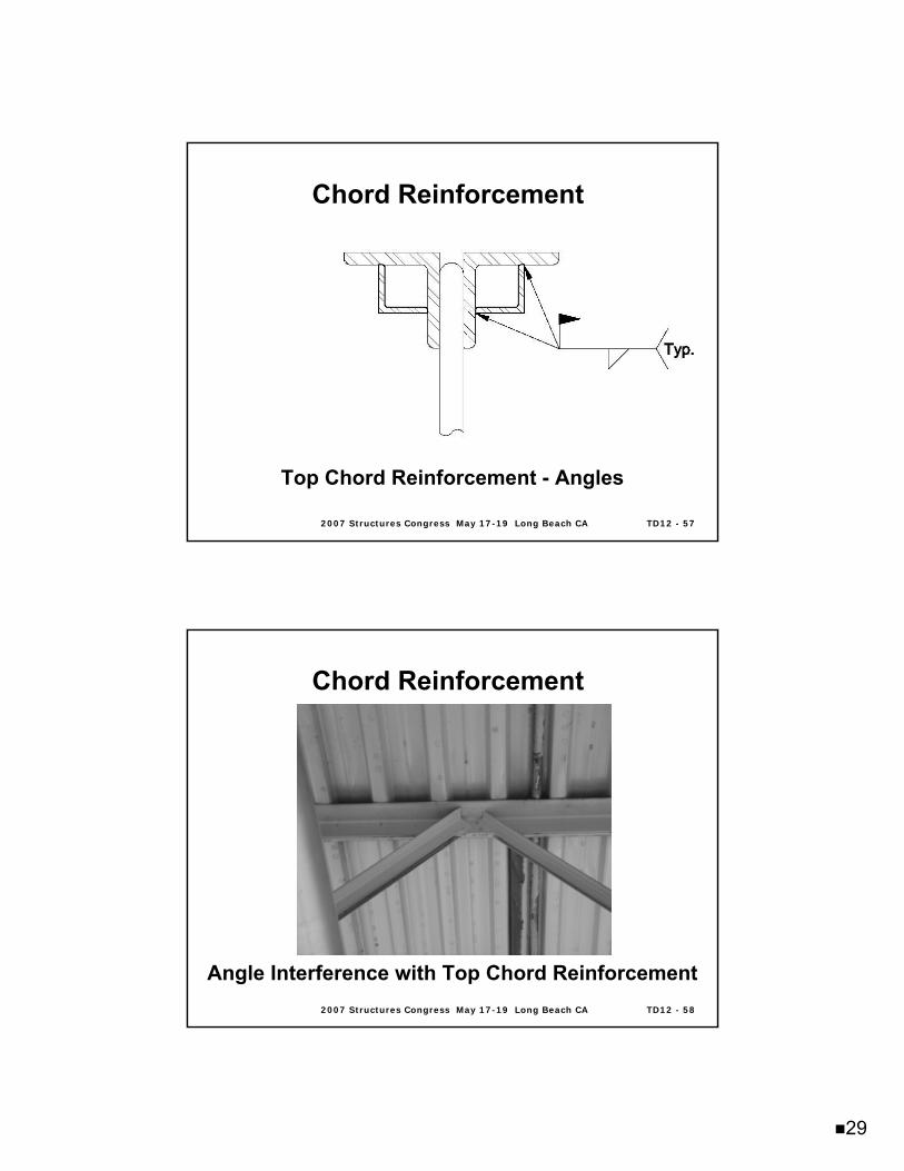
Chord ReinforcementChord Reinforcement
Typical reinforcement detailsTop chord• More difficult to reinforce since the floor or
roof deck is usually in place• Overhead welds may be required
Bottom chord• Easier to access• No overhead welds required
2007 Structures Congress May 172007 Structures Congress May 17--19 Long Beach CA19 Long Beach CA TD12 TD12 -- 5454
Top Chord Reinforcement - Rods
Chord ReinforcementChord Reinforcement
28
2007 Structures Congress May 172007 Structures Congress May 17--19 Long Beach CA19 Long Beach CA TD12 TD12 -- 5555
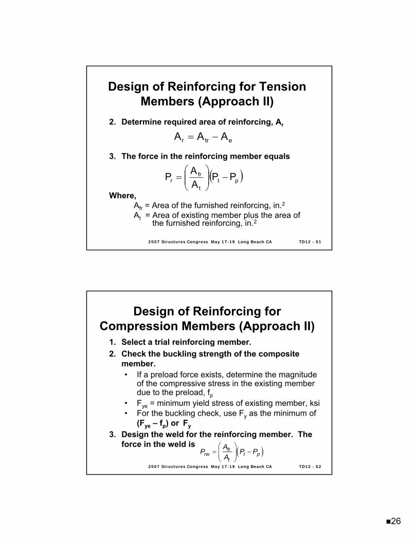
Top Chord Reinforcement - Plates
Chord ReinforcementChord Reinforcement
2007 Structures Congress May 172007 Structures Congress May 17--19 Long Beach CA19 Long Beach CA TD12 TD12 -- 5656
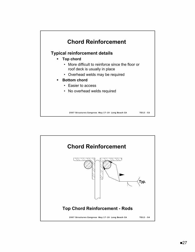
Top Chord Reinforcement - Angles
Chord ReinforcementChord Reinforcement
29
2007 Structures Congress May 172007 Structures Congress May 17--19 Long Beach CA19 Long Beach CA TD12 TD12 -- 5757
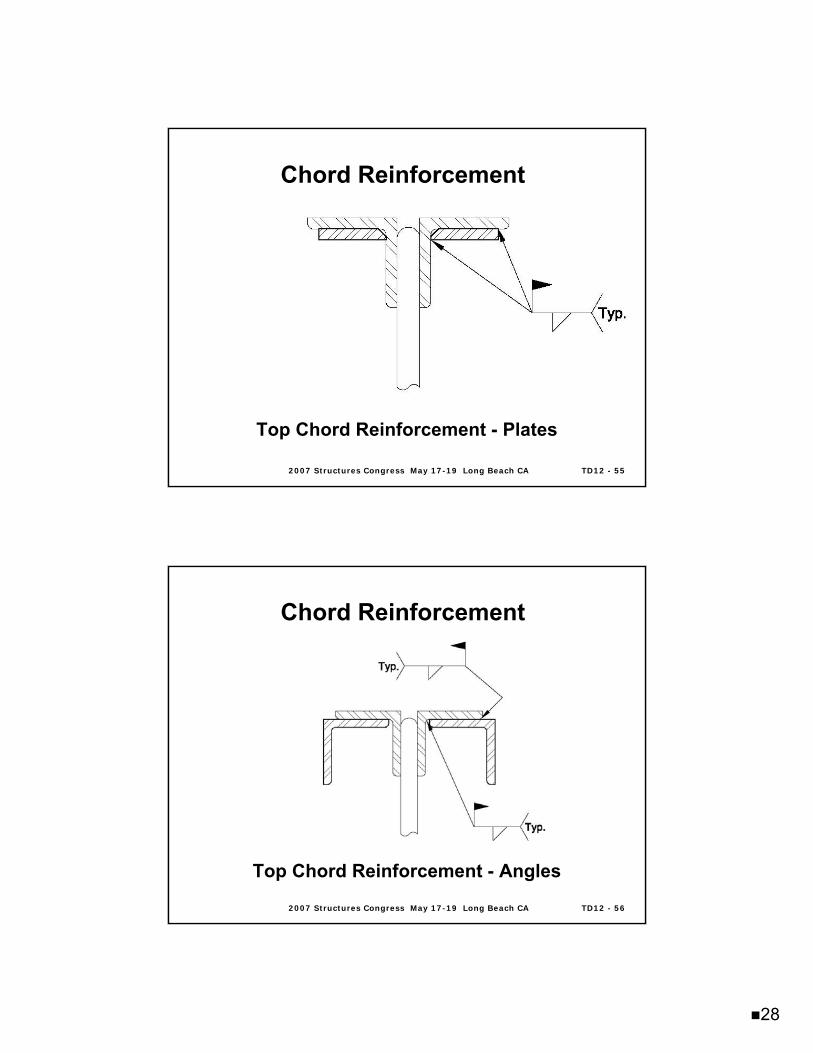
Top Chord Reinforcement - Angles
Chord ReinforcementChord Reinforcement
2007 Structures Congress May 172007 Structures Congress May 17--19 Long Beach CA19 Long Beach CA TD12 TD12 -- 5858
Angle Interference with Top Chord Reinforcement
Chord ReinforcementChord Reinforcement
30
2007 Structures Congress May 172007 Structures Congress May 17--19 Long Beach CA19 Long Beach CA TD12 TD12 -- 5959
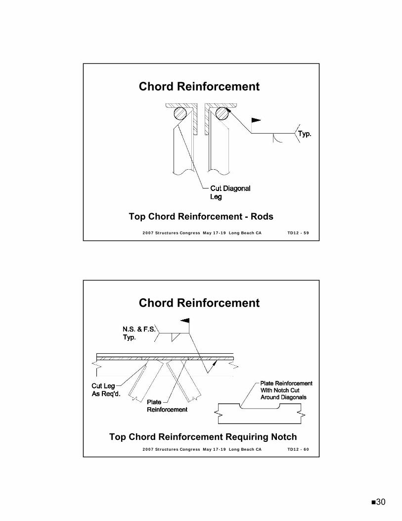
Top Chord Reinforcement - Rods
Chord ReinforcementChord Reinforcement
2007 Structures Congress May 172007 Structures Congress May 17--19 Long Beach CA19 Long Beach CA TD12 TD12 -- 6060
Top Chord Reinforcement Requiring Notch
Chord ReinforcementChord Reinforcement
31
2007 Structures Congress May 172007 Structures Congress May 17--19 Long Beach CA19 Long Beach CA TD12 TD12 -- 6161
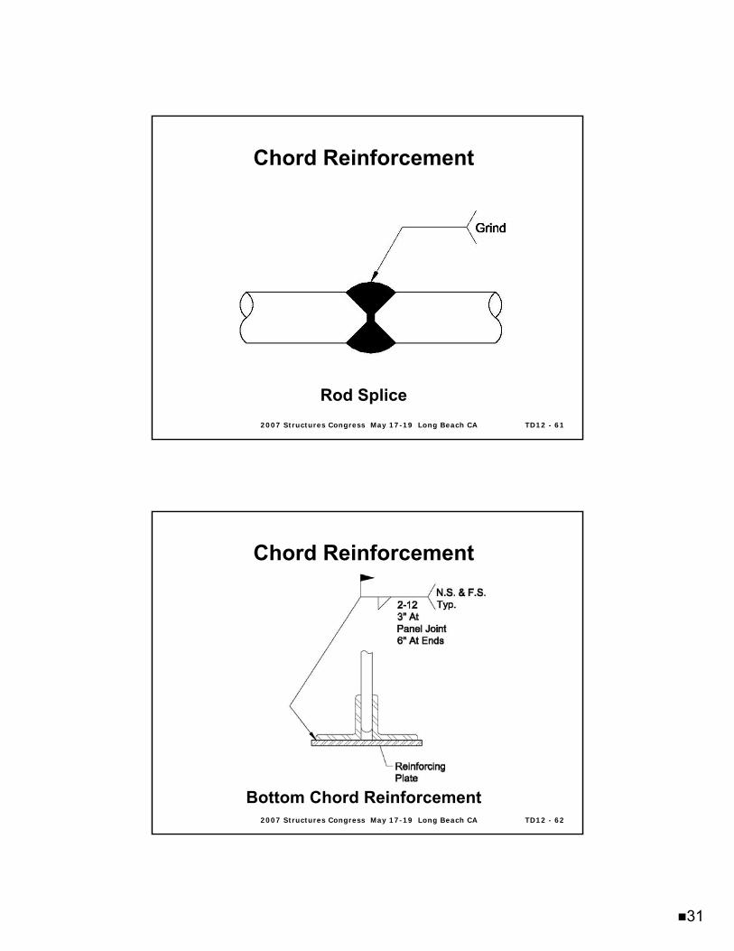
Rod Splice
Chord ReinforcementChord Reinforcement
2007 Structures Congress May 172007 Structures Congress May 17--19 Long Beach CA19 Long Beach CA TD12 TD12 -- 6262
Bottom Chord Reinforcement
Chord ReinforcementChord Reinforcement
32
2007 Structures Congress May 172007 Structures Congress May 17--19 Long Beach CA19 Long Beach CA TD12 TD12 -- 6363
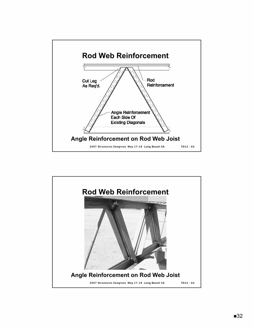
Rod Web ReinforcementRod Web Reinforcement
Angle Reinforcement on Rod Web Joist
2007 Structures Congress May 172007 Structures Congress May 17--19 Long Beach CA19 Long Beach CA TD12 TD12 -- 6464
Rod Web ReinforcementRod Web Reinforcement
Angle Reinforcement on Rod Web Joist
33
2007 Structures Congress May 172007 Structures Congress May 17--19 Long Beach CA19 Long Beach CA TD12 TD12 -- 6565
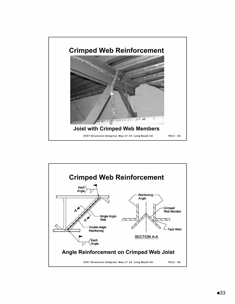
Crimped Web ReinforcementCrimped Web Reinforcement
Joist with Crimped Web Members
2007 Structures Congress May 172007 Structures Congress May 17--19 Long Beach CA19 Long Beach CA TD12 TD12 -- 6666
Crimped Web ReinforcementCrimped Web Reinforcement
Angle Reinforcement on Crimped Web Joist
34
2007 Structures Congress May 172007 Structures Congress May 17--19 Long Beach CA19 Long Beach CA TD12 TD12 -- 6767
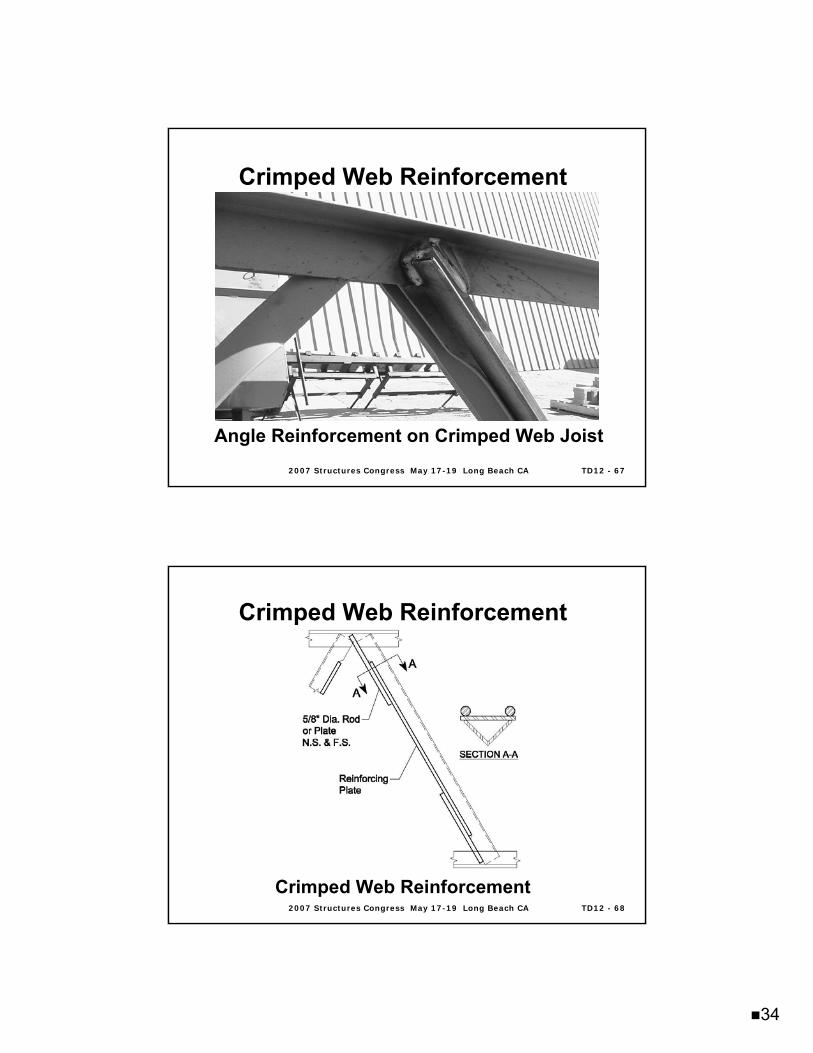
Crimped Web ReinforcementCrimped Web Reinforcement
Angle Reinforcement on Crimped Web Joist
2007 Structures Congress May 172007 Structures Congress May 17--19 Long Beach CA19 Long Beach CA TD12 TD12 -- 6868
Crimped Web ReinforcementCrimped Web Reinforcement
Crimped Web Reinforcement
35
2007 Structures Congress May 172007 Structures Congress May 17--19 Long Beach CA19 Long Beach CA TD12 TD12 -- 6969
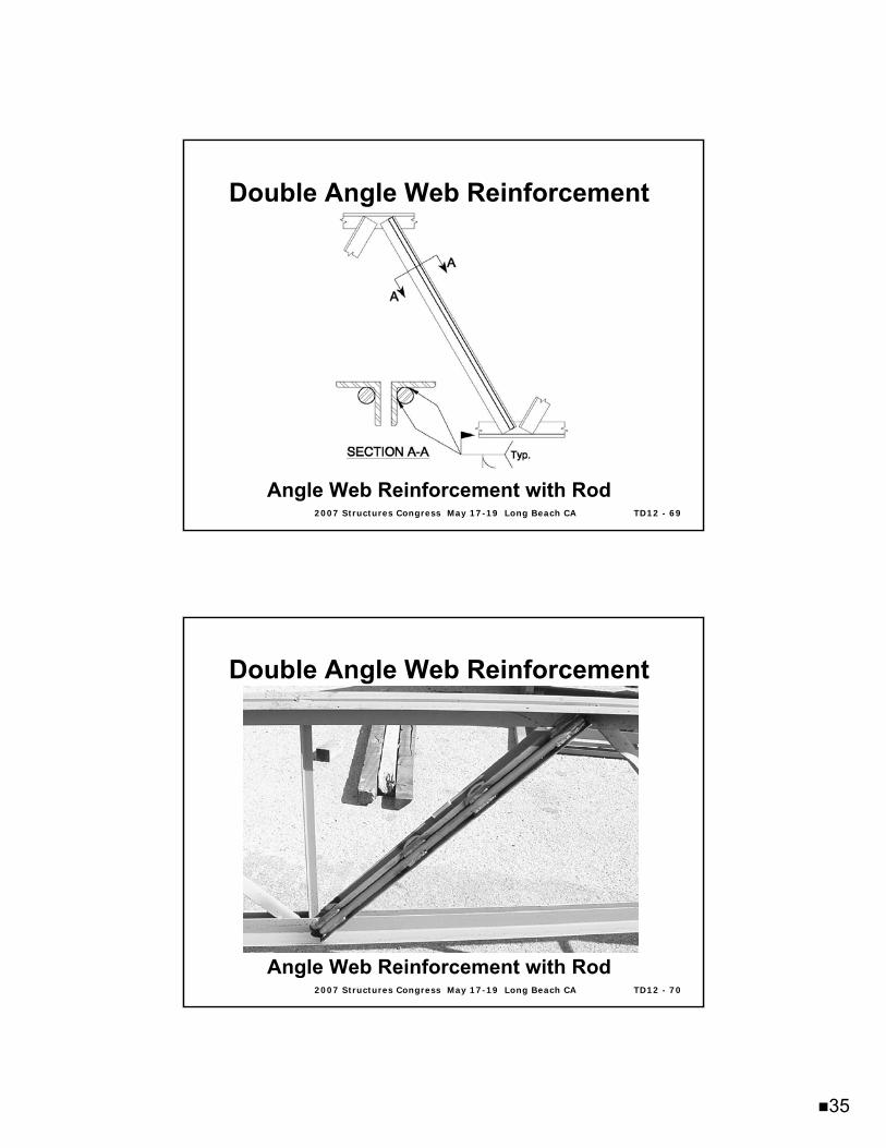
Double Angle Web ReinforcementDouble Angle Web Reinforcement
Angle Web Reinforcement with Rod
2007 Structures Congress May 172007 Structures Congress May 17--19 Long Beach CA19 Long Beach CA TD12 TD12 -- 7070
Double Angle Web ReinforcementDouble Angle Web Reinforcement
Angle Web Reinforcement with Rod
36
2007 Structures Congress May 172007 Structures Congress May 17--19 Long Beach CA19 Long Beach CA TD12 TD12 -- 7171
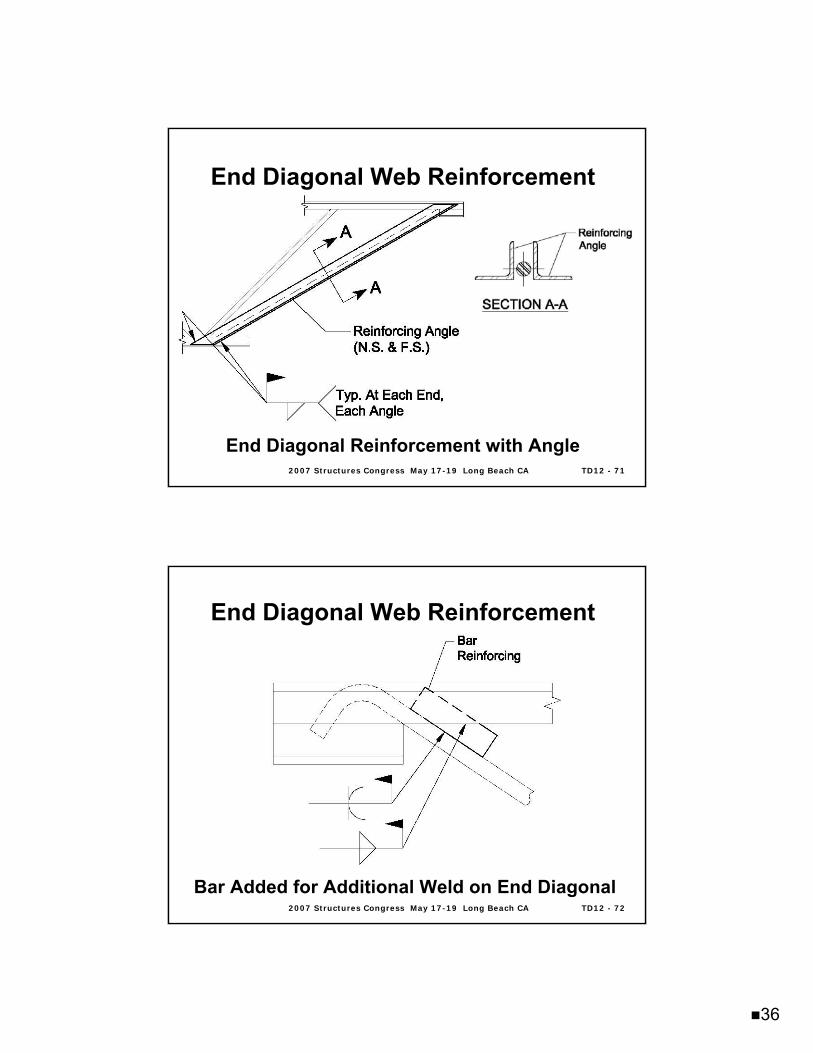
End Diagonal Web ReinforcementEnd Diagonal Web Reinforcement
End Diagonal Reinforcement with Angle
2007 Structures Congress May 172007 Structures Congress May 17--19 Long Beach CA19 Long Beach CA TD12 TD12 -- 7272
End Diagonal Web ReinforcementEnd Diagonal Web Reinforcement
Bar Added for Additional Weld on End Diagonal
37
2007 Structures Congress May 172007 Structures Congress May 17--19 Long Beach CA19 Long Beach CA TD12 TD12 -- 7373
Design Examples for Strengthening Design Examples for Strengthening JoistsJoists
Example 3.1 Strengthening a K-Series Joist with Crimped Angle Webs
Example 3.2 Strengthening a K-Series Joist with Rod Webs
Example 3.3 Strengthening an End Diagonal (W2) using Double Angles
Example 3.4 Strengthening of Joist Girder Chords
Example 3.5 Strengthening of a LH-Series Joist with Double Angle Webs
Example 3.6 Design of a Strut to Prevent Top Chord Bending between Panel Points
2007 Structures Congress May 172007 Structures Congress May 17--19 Long Beach CA19 Long Beach CA TD12 TD12 -- 7474
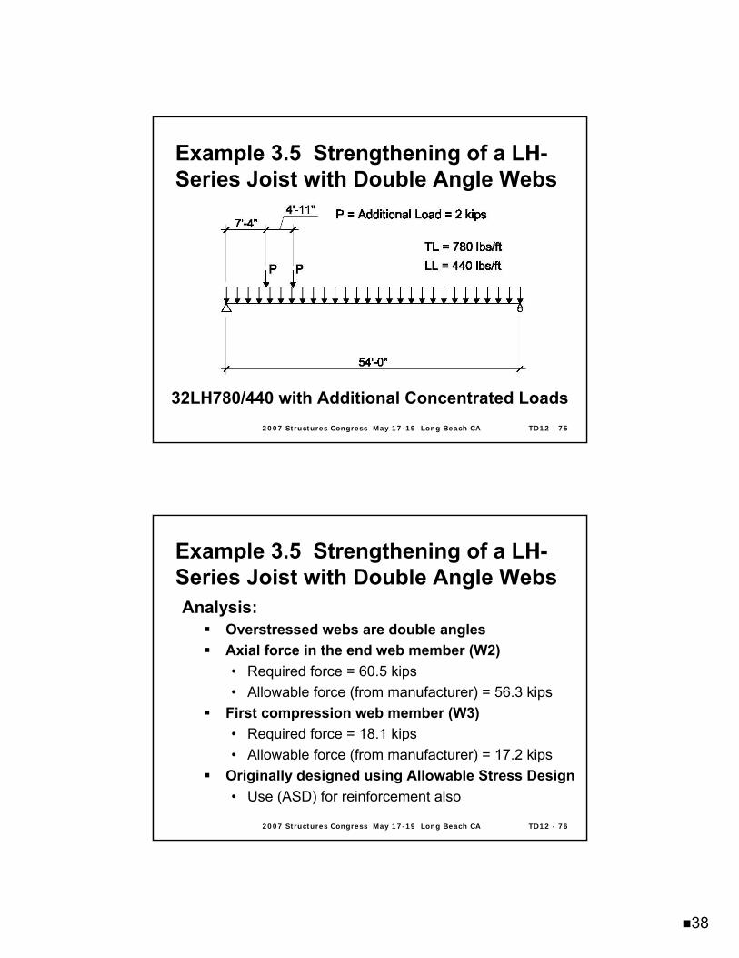
Given Conditions:A remodel requires that additional equipment be installed and supported by the joistsOriginal joists were designated as 32LH780/440Added equipment will be centered over two joists• Resulting load is 2000 lbs located at 7’-4” and
12’-3” from the tag end of the joistUniform loads in the designation are the uniform design loads required• Load redistribution method not a feasible
solution
Example 3.5 Strengthening of a LHExample 3.5 Strengthening of a LH--Series Joist with Double Angle WebsSeries Joist with Double Angle Webs
38
2007 Structures Congress May 172007 Structures Congress May 17--19 Long Beach CA19 Long Beach CA TD12 TD12 -- 7575
32LH780/440 with Additional Concentrated Loads
Example 3.5 Strengthening of a LHExample 3.5 Strengthening of a LH--Series Joist with Double Angle WebsSeries Joist with Double Angle Webs
2007 Structures Congress May 172007 Structures Congress May 17--19 Long Beach CA19 Long Beach CA TD12 TD12 -- 7676
Analysis:Overstressed webs are double anglesAxial force in the end web member (W2)• Required force = 60.5 kips• Allowable force (from manufacturer) = 56.3 kips
First compression web member (W3)• Required force = 18.1 kips• Allowable force (from manufacturer) = 17.2 kips
Originally designed using Allowable Stress Design• Use (ASD) for reinforcement also
Example 3.5 Strengthening of a LHExample 3.5 Strengthening of a LH--Series Joist with Double Angle WebsSeries Joist with Double Angle Webs
39
2007 Structures Congress May 172007 Structures Congress May 17--19 Long Beach CA19 Long Beach CA TD12 TD12 -- 7777
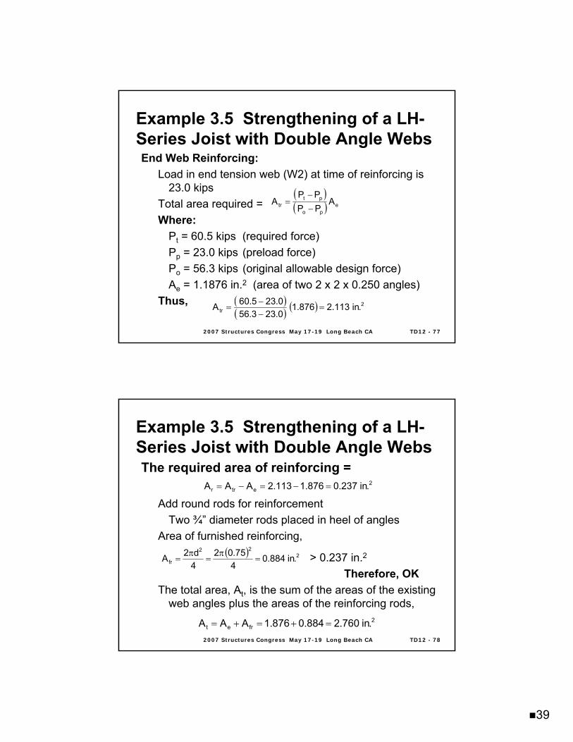
End Web Reinforcing:Load in end tension web (W2) at time of reinforcing is
23.0 kips Total area required =Where:
Pt = 60.5 kips (required force)Pp = 23.0 kips (preload force)Po = 56.3 kips (original allowable design force)Ae = 1.1876 in.2 (area of two 2 x 2 x 0.250 angles)
Thus,
( )( ) e
po
pttr A
PPPP
A−−
=
( )( ) ( ) 2
tr .in113.2876.10.233.560.235.60A =
−−
=
Example 3.5 Strengthening of a LHExample 3.5 Strengthening of a LH--Series Joist with Double Angle WebsSeries Joist with Double Angle Webs
2007 Structures Congress May 172007 Structures Congress May 17--19 Long Beach CA19 Long Beach CA TD12 TD12 -- 7878
The required area of reinforcing =
Add round rods for reinforcementTwo ¾” diameter rods placed in heel of angles
Area of furnished reinforcing,
> 0.237 in.2
Therefore, OKThe total area, At, is the sum of the areas of the existing
web angles plus the areas of the reinforcing rods,
2etrr .in237.0876.1113.2AAA =−=−=
( ) 222
fr .in884.0475.02
4d2A =
π=
π=
2fret .in760.2884.0876.1AAA =+=+=
Example 3.5 Strengthening of a LHExample 3.5 Strengthening of a LH--Series Joist with Double Angle WebsSeries Joist with Double Angle Webs
40
2007 Structures Congress May 172007 Structures Congress May 17--19 Long Beach CA19 Long Beach CA TD12 TD12 -- 7979
The force in the reinforcing members equals
Check the stress in the round rod reinforcing member:
F = P/A =12.01/0.884 = 13.59 ksi < 21.6 ksi
Therefore, the use of A36 material is OK
( ) ( ) kips01.120.235.60760.2884.0PP
AAP pt
t
frr =−⎟
⎠⎞
⎜⎝⎛=−⎟⎟
⎠
⎞⎜⎜⎝
⎛=
Example 3.5 Strengthening of a LHExample 3.5 Strengthening of a LH--Series Joist with Double Angle WebsSeries Joist with Double Angle Webs
2007 Structures Congress May 172007 Structures Congress May 17--19 Long Beach CA19 Long Beach CA TD12 TD12 -- 8080
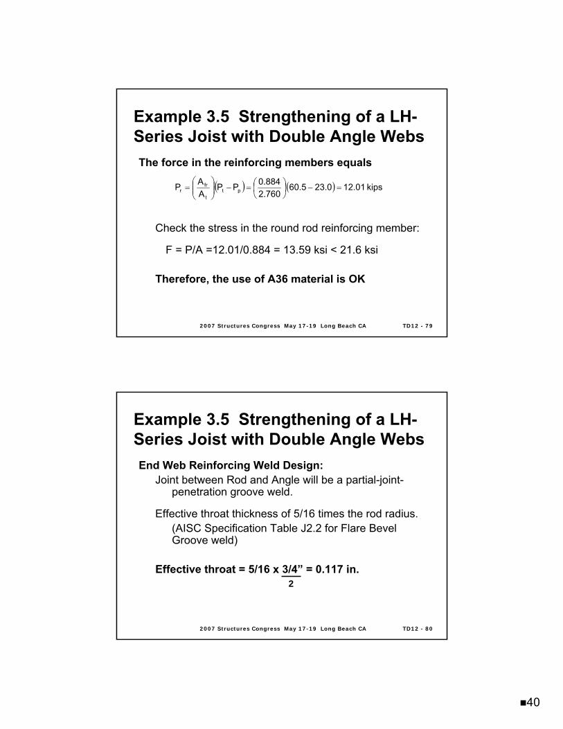
Example 3.5 Strengthening of a LHExample 3.5 Strengthening of a LH--Series Joist with Double Angle WebsSeries Joist with Double Angle WebsEnd Web Reinforcing Weld Design:
Joint between Rod and Angle will be a partial-joint-penetration groove weld.
Effective throat thickness of 5/16 times the rod radius.(AISC Specification Table J2.2 for Flare Bevel Groove weld)
Effective throat = 5/16 x 3/4” = 0.117 in.2
41
2007 Structures Congress May 172007 Structures Congress May 17--19 Long Beach CA19 Long Beach CA TD12 TD12 -- 8181
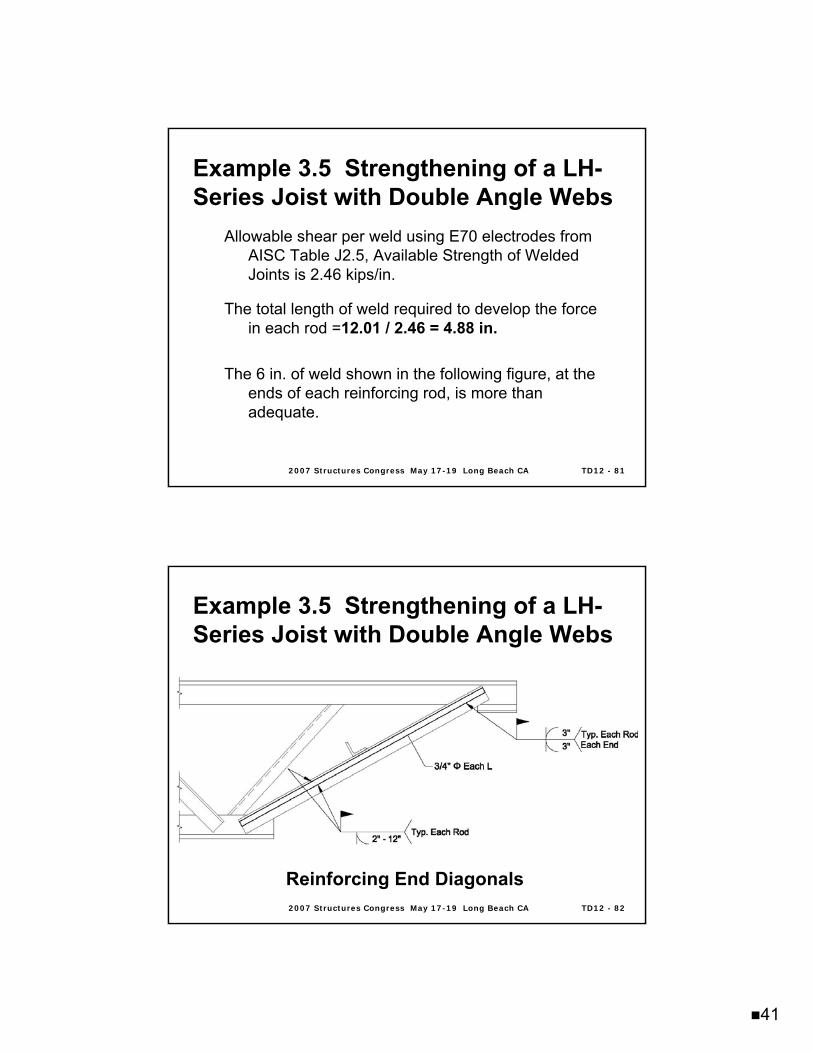
Allowable shear per weld using E70 electrodes from AISC Table J2.5, Available Strength of Welded Joints is 2.46 kips/in.
The total length of weld required to develop the force in each rod =12.01 / 2.46 = 4.88 in.
The 6 in. of weld shown in the following figure, at the ends of each reinforcing rod, is more than adequate.
Example 3.5 Strengthening of a LHExample 3.5 Strengthening of a LH--Series Joist with Double Angle WebsSeries Joist with Double Angle Webs
2007 Structures Congress May 172007 Structures Congress May 17--19 Long Beach CA19 Long Beach CA TD12 TD12 -- 8282
Reinforcing End Diagonals
Example 3.5 Strengthening of a LHExample 3.5 Strengthening of a LH--Series Joist with Double Angle WebsSeries Joist with Double Angle Webs
42
2007 Structures Congress May 172007 Structures Congress May 17--19 Long Beach CA19 Long Beach CA TD12 TD12 -- 8383
End Web Weld Design for Total Required Force:
Pt = 60.5 kipsBased on 3/16” fillet weld and using E70
electrodes, the allowable shear per inch of weld equals:
(0.707)(0.188 in.)(21 ksi) = 2.79 kips/in.
Thus, 60.5/2.79 = 21.7 in. (use 11 in. at each end of each web angle)
Example 3.5 Strengthening of a LHExample 3.5 Strengthening of a LH--Series Joist with Double Angle WebsSeries Joist with Double Angle Webs
2007 Structures Congress May 172007 Structures Congress May 17--19 Long Beach CA19 Long Beach CA TD12 TD12 -- 8484
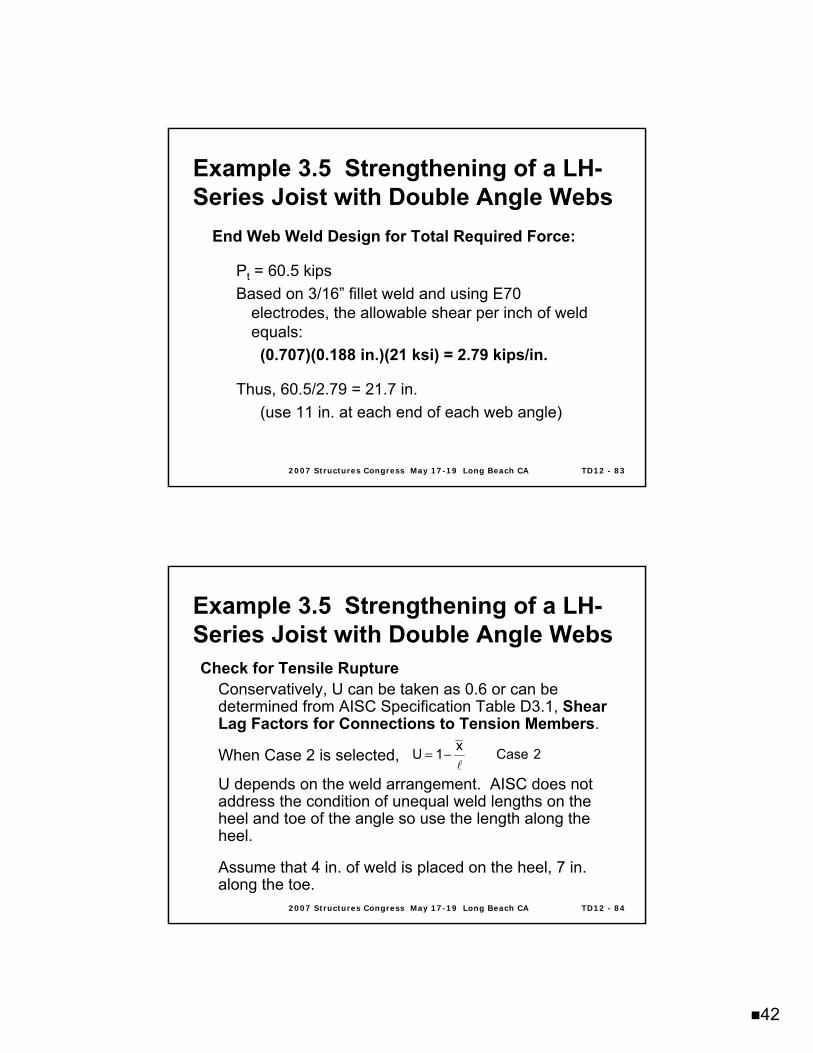
Example 3.5 Strengthening of a LHExample 3.5 Strengthening of a LH--Series Joist with Double Angle WebsSeries Joist with Double Angle WebsCheck for Tensile Rupture
Conservatively, U can be taken as 0.6 or can be determined from AISC Specification Table D3.1, Shear Lag Factors for Connections to Tension Members.
When Case 2 is selected,
U depends on the weld arrangement. AISC does not address the condition of unequal weld lengths on the heel and toe of the angle so use the length along the heel.
Assume that 4 in. of weld is placed on the heel, 7 in. along the toe.
2Casex1Ul
−=
43
2007 Structures Congress May 172007 Structures Congress May 17--19 Long Beach CA19 Long Beach CA TD12 TD12 -- 8585
Example 3.5 Strengthening of a LHExample 3.5 Strengthening of a LH--Series Joist with Double Angle WebsSeries Joist with Double Angle Webs
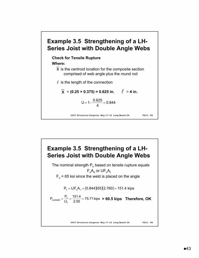
Check for Tensile Rupture Where:
is the centroid location for the composite section comprised of web angle plus the round rod
is the length of the connection
x
844.04625.01U =−=
l
x l= (0.25 + 0.375) = 0.625 in. = 4 in.
2007 Structures Congress May 172007 Structures Congress May 17--19 Long Beach CA19 Long Beach CA TD12 TD12 -- 8686
The nominal strength Pn based on tensile rupture equalsFuAe or UFuAt
Fu = 65 ksi since the weld is placed on the angle
> 60.5 kips Therefore, OK
( )( )( ) kips4.151760.265844.0AFUP tun ===
kips71.7500.2
4.151PPt
navailable ==
Ω=
Example 3.5 Strengthening of a LHExample 3.5 Strengthening of a LH--Series Joist with Double Angle WebsSeries Joist with Double Angle Webs
44
2007 Structures Congress May 172007 Structures Congress May 17--19 Long Beach CA19 Long Beach CA TD12 TD12 -- 8787
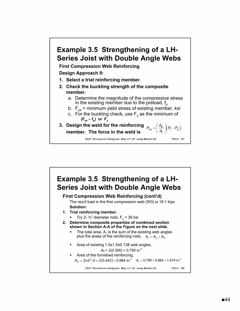
First Compression Web ReinforcingDesign Approach II:1. Select a trial reinforcing member.2. Check the buckling strength of the composite
member.a. Determine the magnitude of the compressive stress
in the existing member due to the preload, fpb. Fye = minimum yield stress of existing member, ksic. For the buckling check, use Fy as the minimum of
(Fye – fp) or Fy
3. Design the weld for the reinforcing member. The force in the weld is
( )⎛ ⎞= −⎜ ⎟⎝ ⎠
frrw t p
t
AP P PA
Example 3.5 Strengthening of a LHExample 3.5 Strengthening of a LH--Series Joist with Double Angle WebsSeries Joist with Double Angle Webs
2007 Structures Congress May 172007 Structures Congress May 17--19 Long Beach CA19 Long Beach CA TD12 TD12 -- 8888
First Compression Web Reinforcing (cont’d)The req’d load in the first compression web (W3) is 18.1 kipsSolution:
1. Trial reinforcing member. Try 2- ¾” diameter rods, Fy = 36 ksi
2. Determine composite properties of combined section shown in Section A-A of the Figure on the next slide.
The total area, A, is the sum of the existing web angles plus the areas of the reinforcing rods,
Area of existing 1.5x1.5x0.138 web angles,
Area of the furnished reinforcing,
fret AAA +=
( ) 22fr .in884.0442.024d2A ==π= 2
t .in674.1884.0790.0A =+=
2e A = 2(0.395) = 0.790 in.
Example 3.5 Strengthening of a LHExample 3.5 Strengthening of a LH--Series Joist with Double Angle WebsSeries Joist with Double Angle Webs
45
2007 Structures Congress May 172007 Structures Congress May 17--19 Long Beach CA19 Long Beach CA TD12 TD12 -- 8989
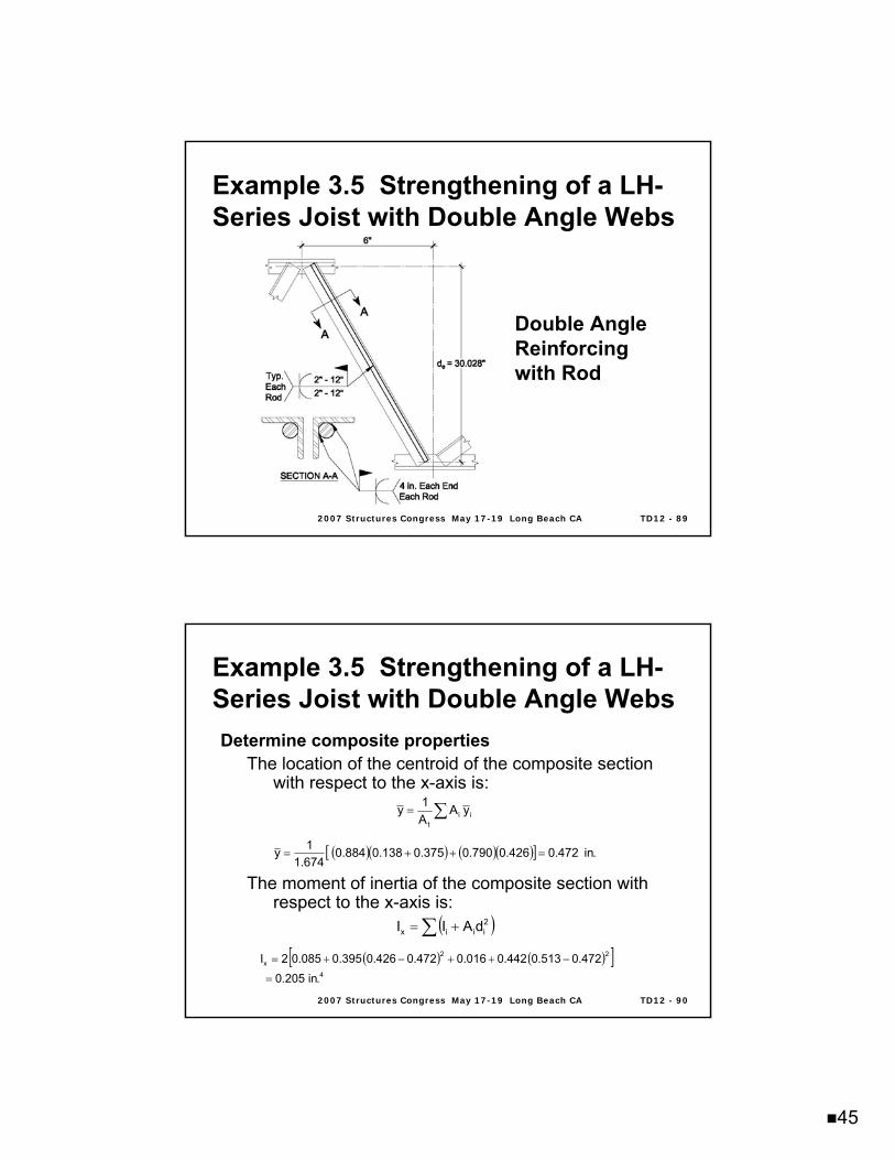
Double Angle Reinforcing with Rod
Example 3.5 Strengthening of a LHExample 3.5 Strengthening of a LH--Series Joist with Double Angle WebsSeries Joist with Double Angle Webs
2007 Structures Congress May 172007 Structures Congress May 17--19 Long Beach CA19 Long Beach CA TD12 TD12 -- 9090
Determine composite propertiesThe location of the centroid of the composite section
with respect to the x-axis is:
The moment of inertia of the composite section with respect to the x-axis is:
∑= iit
yAA1y
( )( ) ( )( )[ ] .in472.0426.0790.0375.0138.0884.0674.11y =++=
( )∑ += 2iiix dAII
( ) ( )[ ]4
22x
.in205.0472.0513.0442.0016.0472.0426.0395.0085.02I
=
−++−+=
Example 3.5 Strengthening of a LHExample 3.5 Strengthening of a LH--Series Joist with Double Angle WebsSeries Joist with Double Angle Webs
46
2007 Structures Congress May 172007 Structures Congress May 17--19 Long Beach CA19 Long Beach CA TD12 TD12 -- 9191
Determine composite properties (cont’d)
The radius of gyration of the composite section with respect to the x-axis is:
t
xx A
Ir =
.in350.0674.1205.0rx ==
Example 3.5 Strengthening of a LHExample 3.5 Strengthening of a LH--Series Joist with Double Angle WebsSeries Joist with Double Angle Webs
2007 Structures Congress May 172007 Structures Congress May 17--19 Long Beach CA19 Long Beach CA TD12 TD12 -- 9292
Check buckling strength of the composite section:For compression webs, the allowable load is determined using AISC Specification Chapter E.
Where,Pc is the allowable compressive strength, , kipsFa is the allowable compressive stress, , ksiAt is the composite member cross-sectional area, in.2Safety factor,
tac AFP =
67.1c =Ω
cnP Ω
ccrF Ω
Example 3.5 Strengthening of a LHExample 3.5 Strengthening of a LH--Series Joist with Double Angle WebsSeries Joist with Double Angle Webs
47
2007 Structures Congress May 172007 Structures Congress May 17--19 Long Beach CA19 Long Beach CA TD12 TD12 -- 9393
Check buckling strength of the composite section (cont’d):
Determine the yield stress to be used:Preload, Pp = 6.9 kips
Yield stress to be used in the minimum of:
Fye – fp = 50 – 8.73 = 41.27 ksi
Fy = 36 ksi for the rods Thus, use 36 ksi
( )( ) ksi73.8395.029.6fp ==
Example 3.5 Strengthening of a LHExample 3.5 Strengthening of a LH--Series Joist with Double Angle WebsSeries Joist with Double Angle Webs
2007 Structures Congress May 172007 Structures Congress May 17--19 Long Beach CA19 Long Beach CA TD12 TD12 -- 9494
Check buckling strength of the composite section (cont’d):
Determine form factor, Qs:
When (AISC E7-10)
Thus, Qs = 1.0
0.1QFE45.0
tb
sy
=≤
0.451.5 2900010.87 0.45 12.770.138 36y
EF
=≤ ==
Example 3.5 Strengthening of a LHExample 3.5 Strengthening of a LH--Series Joist with Double Angle WebsSeries Joist with Double Angle Webs
48
2007 Structures Congress May 172007 Structures Congress May 17--19 Long Beach CA19 Long Beach CA TD12 TD12 -- 9595
Check buckling strength of the composite section (cont’d):
Determine Critical Stress, Fcr:
When (AISC E3-2)
When (AISC E3-3)
Where (AISC E3-4)
yFF
cry
F658.0FFE71.4
rKL
e
y
⎥⎥⎦
⎤
⎢⎢⎣
⎡=≤
ecry
F877.0FFE71.4
rKL
=>
2
2
e
rKL
EF
⎟⎠⎞
⎜⎝⎛
π=
Example 3.5 Strengthening of a LHExample 3.5 Strengthening of a LH--Series Joist with Double Angle WebsSeries Joist with Double Angle Webs
2007 Structures Congress May 172007 Structures Congress May 17--19 Long Beach CA19 Long Beach CA TD12 TD12 -- 9696
Check buckling strength of the composite section (cont’d):
Compute Slenderness Ratio of Composite Section:
( ) ( ) .in62.30028.306L 22 =+=
68.13336
2900071.449.87350.0
62.30rL
=<==
( ) ksi39.37
350.062.30
29000F 2
2
e =
⎟⎠⎞
⎜⎝⎛
π=
Example 3.5 Strengthening of a LHExample 3.5 Strengthening of a LH--Series Joist with Double Angle WebsSeries Joist with Double Angle Webs
49
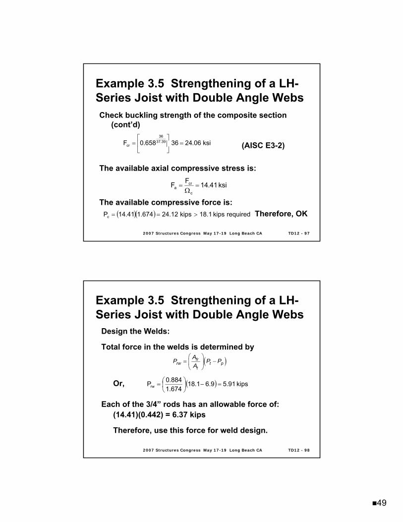
2007 Structures Congress May 172007 Structures Congress May 17--19 Long Beach CA19 Long Beach CA TD12 TD12 -- 9797
Check buckling strength of the composite section (cont’d)
(AISC E3-2)
The available axial compressive stress is:
The available compressive force is:Therefore, OK
ksi06.2436658.0F 39.3736
cr =⎥⎦
⎤⎢⎣
⎡=
ksi41.14FFc
cra =
Ω=
( )( ) requiredkips1.18kips12.24674.141.14Pc >==
Example 3.5 Strengthening of a LHExample 3.5 Strengthening of a LH--Series Joist with Double Angle WebsSeries Joist with Double Angle Webs
2007 Structures Congress May 172007 Structures Congress May 17--19 Long Beach CA19 Long Beach CA TD12 TD12 -- 9898
Design the Welds:
Total force in the welds is determined by
Or,
Each of the 3/4” rods has an allowable force of:(14.41)(0.442) = 6.37 kips
Therefore, use this force for weld design.
( )⎛ ⎞= −⎜ ⎟⎝ ⎠
frrw t p
t
AP P PA
( ) kips91.59.61.18674.1884.0Prw =−⎟
⎠⎞
⎜⎝⎛=
Example 3.5 Strengthening of a LHExample 3.5 Strengthening of a LH--Series Joist with Double Angle WebsSeries Joist with Double Angle Webs
50
2007 Structures Congress May 172007 Structures Congress May 17--19 Long Beach CA19 Long Beach CA TD12 TD12 -- 9999
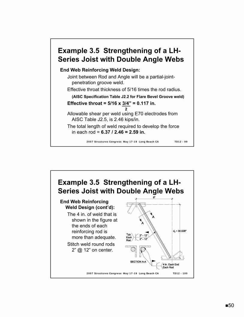
End Web Reinforcing Weld Design: Joint between Rod and Angle will be a partial-joint-
penetration groove weld.Effective throat thickness of 5/16 times the rod radius.
(AISC Specification Table J2.2 for Flare Bevel Groove weld)Effective throat = 5/16 x 3/4” = 0.117 in.
Allowable shear per weld using E70 electrodes from AISC Table J2.5, is 2.46 kips/in.
The total length of weld required to develop the force in each rod = 6.37 / 2.46 = 2.59 in.
Example 3.5 Strengthening of a LHExample 3.5 Strengthening of a LH--Series Joist with Double Angle WebsSeries Joist with Double Angle Webs
2
2007 Structures Congress May 172007 Structures Congress May 17--19 Long Beach CA19 Long Beach CA TD12 TD12 -- 100100
End Web Reinforcing Weld Design (cont’d): The 4 in. of weld that is
shown in the figure at the ends of each reinforcing rod is more than adequate.
Stitch weld round rods 2” @ 12” on center.
Example 3.5 Strengthening of a LHExample 3.5 Strengthening of a LH--Series Joist with Double Angle WebsSeries Joist with Double Angle Webs
51
2007 Structures Congress May 172007 Structures Congress May 17--19 Long Beach CA19 Long Beach CA TD12 TD12 -- 101101
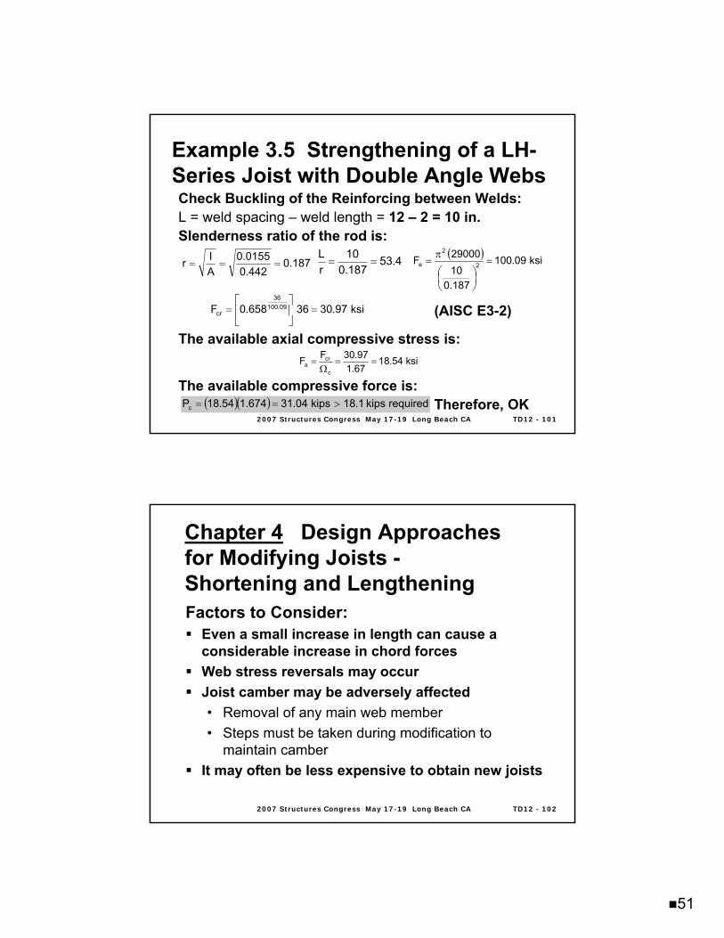
Check Buckling of the Reinforcing between Welds:L = weld spacing – weld length = 12 – 2 = 10 in.Slenderness ratio of the rod is:
(AISC E3-2)
The available axial compressive stress is:
The available compressive force is:Therefore, OK
187.0442.0
0155.0AIr === 4.53
187.010
rL
==( ) ksi09.100
187.01029000F 2
2
e =
⎟⎠⎞
⎜⎝⎛
π=
ksi97.3036658.0F 09.10036
cr =⎥⎦
⎤⎢⎣
⎡=
ksi54.1867.197.30FF
c
cra ==
Ω=
( )( ) requiredkips1.18kips04.31674.154.18Pc >==
Example 3.5 Strengthening of a LHExample 3.5 Strengthening of a LH--Series Joist with Double Angle WebsSeries Joist with Double Angle Webs
2007 Structures Congress May 172007 Structures Congress May 17--19 Long Beach CA19 Long Beach CA TD12 TD12 -- 102102
Chapter 4Chapter 4 Design Approaches Design Approaches for Modifying Joists for Modifying Joists --Shortening and LengtheningShortening and LengtheningFactors to Consider:
Even a small increase in length can cause a considerable increase in chord forcesWeb stress reversals may occurJoist camber may be adversely affected• Removal of any main web member• Steps must be taken during modification to
maintain camberIt may often be less expensive to obtain new joists
52
2007 Structures Congress May 172007 Structures Congress May 17--19 Long Beach CA19 Long Beach CA TD12 TD12 -- 103103
Design Approaches for Modifying Design Approaches for Modifying Joists Joists -- Shortening and LengtheningShortening and LengtheningFactors to Consider (cont’d):
Shortening generally does not require chord reinforcement• Typically requires new bearing seats and end
webs• An unacceptable practice is to cut the end of the
top chord and bend the existing end web back up to the top chord
2007 Structures Congress May 172007 Structures Congress May 17--19 Long Beach CA19 Long Beach CA TD12 TD12 -- 104104
Design Approaches for Modifying Design Approaches for Modifying Joists Joists -- Shortening and LengtheningShortening and LengtheningFactors to Consider (cont’d):
Lengthening requires the addition of reinforcing of the top chord and the web members• A splice at the joist center reduces the web splice
requirement• A splice at the joist end panel reduces the chord
splice requirement but may require web reinforcement
• A splice at both end panels generally requires no web reinforcement
If possible, relocate or change the support for the joists so that joist modification is not necessary
53
2007 Structures Congress May 172007 Structures Congress May 17--19 Long Beach CA19 Long Beach CA TD12 TD12 -- 105105
Design Approaches for Modifying Design Approaches for Modifying Joists Joists -- Shortening and LengtheningShortening and LengtheningSteps to Shorten Open Web Steel Joists
1. Determine the original web layouta. Top chord end panel lengthb. Interior panel lengthc. Number of panels
2. Determine where shortened length occurs relative to top chord panelsa. New end web originates from a bottom chord
panel pointb. Placement angle should be 45 to 70 degrees
3. Determine the loading at the shortened length
2007 Structures Congress May 172007 Structures Congress May 17--19 Long Beach CA19 Long Beach CA TD12 TD12 -- 106106
Design Approaches for Modifying Design Approaches for Modifying Joists Joists -- Shortening and LengtheningShortening and Lengthening
Steps to Shorten Open Web Steel Joists (cont’d)4. Perform a design on the new length
a. Compare material required for new length to material for the as-built length
b. Reinforce undersized existing webs as needed5. Place new bearing seat at the desired location
a. Typically a pair of angles welded between top chord angles
6. Determine the new end web forcea. Typically an end web consists of two new anglesb. Round bars may also be used on smaller
K-Series joists with 2 ½” bearing seats
54
2007 Structures Congress May 172007 Structures Congress May 17--19 Long Beach CA19 Long Beach CA TD12 TD12 -- 107107
Design Approaches for Modifying Design Approaches for Modifying Joists Joists -- Shortening and LengtheningShortening and Lengthening
Steps to Lengthen Open Web Steel Joists1. Determine the original web layout
a. Top chord end panel lengthb. Interior panel lengthc. Number of panels
2. Determine where lengthening length occurs relative to top chord panelsa. Limited to how much length can be added by
1) Slenderness ratio of new web2) Long end panel may govern top chord size
3. Determine the loading at the increased length
2007 Structures Congress May 172007 Structures Congress May 17--19 Long Beach CA19 Long Beach CA TD12 TD12 -- 108108
Design Approaches for Modifying Design Approaches for Modifying Joists Joists -- Shortening and LengtheningShortening and Lengthening
Steps to Lengthen Open Web Steel Joists (cont’d)4. Perform a design on the new length
a. Compare material required for new length to material for the as-built length
b. Reinforce chords and webs as required5. Place and weld new top chord angles
a. Use pre-qualified butt weld per AWS orb. Splice with new material and a weld sized to
develop adequate strength
55
2007 Structures Congress May 172007 Structures Congress May 17--19 Long Beach CA19 Long Beach CA TD12 TD12 -- 109109
Design Approaches for Modifying Design Approaches for Modifying Joists Joists -- Shortening and LengtheningShortening and Lengthening
Steps to Lengthen Open Web Steel Joists (cont’d)6. Place new bearing seat at the desired
locationa. Typically a pair of angles welded between top
chord angles7. Determine the new end web force
a. Typically an end web consists of two new anglesb. Round bars may also be used on smaller
K-Series joists with 2 ½” bearing seats
2007 Structures Congress May 172007 Structures Congress May 17--19 Long Beach CA19 Long Beach CA TD12 TD12 -- 110110
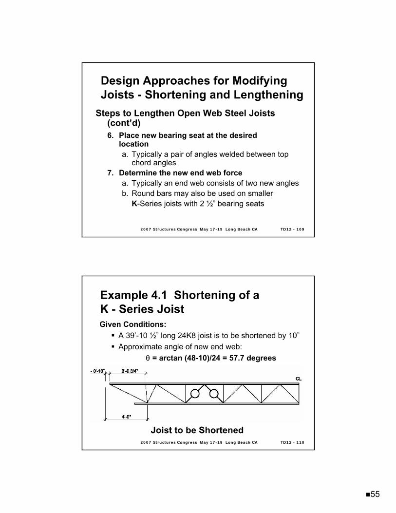
Given Conditions: A 39’-10 ½” long 24K8 joist is to be shortened by 10”Approximate angle of new end web:
θ = arctan (48-10)/24 = 57.7 degrees
Joist to be Shortened
Example 4.1 Shortening of a Example 4.1 Shortening of a K K -- Series JoistSeries Joist
56
2007 Structures Congress May 172007 Structures Congress May 17--19 Long Beach CA19 Long Beach CA TD12 TD12 -- 111111
Analysis and modification:From the Standard ASD Load Table for Open Web Steel Joists, K-Series• New total safe uniformly distributed load
capacity = 293 plfAnalysis shows the two circled webs are overstressed• Reinforce as needed• Webs are crimped angle web members
Reinforce with a pair of angles on the outside of the chords
Example 4.1 Shortening of a Example 4.1 Shortening of a K K -- Series JoistSeries Joist
2007 Structures Congress May 172007 Structures Congress May 17--19 Long Beach CA19 Long Beach CA TD12 TD12 -- 112112
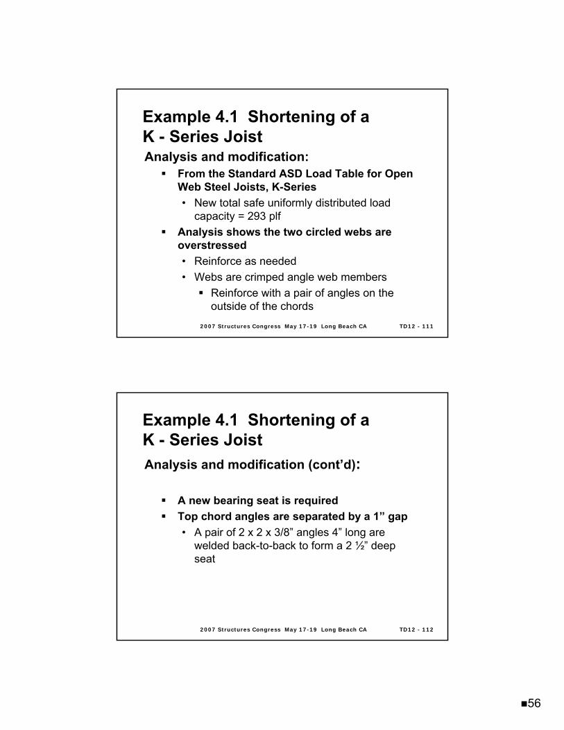
Analysis and modification (cont’d):
A new bearing seat is requiredTop chord angles are separated by a 1” gap• A pair of 2 x 2 x 3/8” angles 4” long are
welded back-to-back to form a 2 ½” deep seat
Example 4.1 Shortening of a Example 4.1 Shortening of a K K -- Series JoistSeries Joist
57
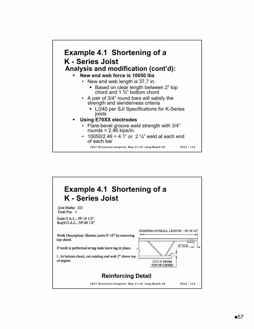
2007 Structures Congress May 172007 Structures Congress May 17--19 Long Beach CA19 Long Beach CA TD12 TD12 -- 113113
Analysis and modification (cont’d):New end web force is 10050 lbs• New end web length is 37.7 in.
Based on clear length between 2” top chord and 1 ¾” bottom chord
• A pair of 3/4” round bars will satisfy the strength and slenderness criteria
L/240 per SJI Specifications for K-Series joists
Using E70XX electrodes• Flare-bevel groove weld strength with 3/4”
rounds = 2.46 kips/in.• 10050/2.46 = 4.1” or 2 ¼” weld at each end
of each bar
Example 4.1 Shortening of a Example 4.1 Shortening of a K K -- Series JoistSeries Joist
2007 Structures Congress May 172007 Structures Congress May 17--19 Long Beach CA19 Long Beach CA TD12 TD12 -- 114114
Reinforcing Detail
Example 4.1 Shortening of a Example 4.1 Shortening of a K K -- Series JoistSeries Joist
58
2007 Structures Congress May 172007 Structures Congress May 17--19 Long Beach CA19 Long Beach CA TD12 TD12 -- 115115
Reinforcing Detail (cont’d)
Example 4.1 Shortening of a Example 4.1 Shortening of a K K -- Series JoistSeries Joist
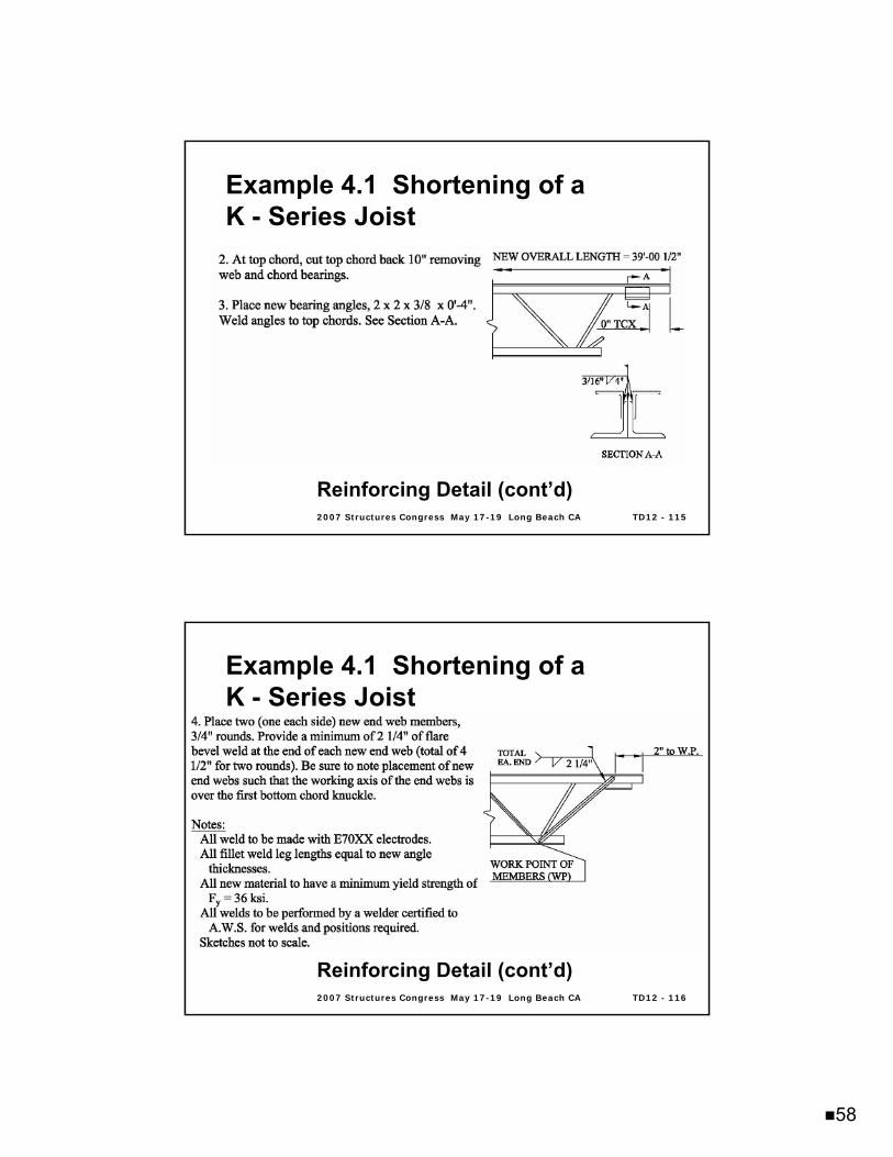
2007 Structures Congress May 172007 Structures Congress May 17--19 Long Beach CA19 Long Beach CA TD12 TD12 -- 116116
Reinforcing Detail (cont’d)
Example 4.1 Shortening of a Example 4.1 Shortening of a K K -- Series JoistSeries Joist
59
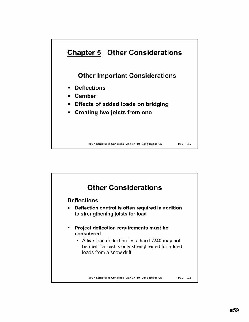
2007 Structures Congress May 172007 Structures Congress May 17--19 Long Beach CA19 Long Beach CA TD12 TD12 -- 117117
Chapter 5Chapter 5 Other ConsiderationsOther Considerations
Other Important Considerations
DeflectionsCamberEffects of added loads on bridgingCreating two joists from one
2007 Structures Congress May 172007 Structures Congress May 17--19 Long Beach CA19 Long Beach CA TD12 TD12 -- 118118
Other ConsiderationsOther ConsiderationsDeflections
Deflection control is often required in addition to strengthening joists for load
Project deflection requirements must be considered• A live load deflection less than L/240 may not
be met if a joist is only strengthened for added loads from a snow drift.
60
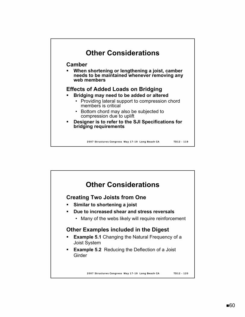
2007 Structures Congress May 172007 Structures Congress May 17--19 Long Beach CA19 Long Beach CA TD12 TD12 -- 119119
Other ConsiderationsOther ConsiderationsCamber
When shortening or lengthening a joist, camber needs to be maintained whenever removing any web members
Effects of Added Loads on BridgingBridging may need to be added or altered• Providing lateral support to compression chord
members is critical• Bottom chord may also be subjected to
compression due to upliftDesigner is to refer to the SJI Specifications for bridging requirements
2007 Structures Congress May 172007 Structures Congress May 17--19 Long Beach CA19 Long Beach CA TD12 TD12 -- 120120
Other ConsiderationsOther ConsiderationsCreating Two Joists from One
Similar to shortening a joistDue to increased shear and stress reversals• Many of the webs likely will require reinforcement
Other Examples included in the DigestExample 5.1 Changing the Natural Frequency of a Joist SystemExample 5.2 Reducing the Deflection of a Joist Girder

61
2007 Structures Congress May 172007 Structures Congress May 17--19 Long Beach CA19 Long Beach CA TD12 TD12 -- 121121
Chapter 6Chapter 6 SummarySummaryApproaches have been Presented for the Modification and Strengthening of Joists
Several types of reinforcing members presented along with attachment detailsProcedures and details do not constitute an exhaustive list of how to reinforce
They provide the designer with ideas and concepts to solve individual modification and strengthening requirements
2007 Structures Congress May 172007 Structures Congress May 17--19 Long Beach CA19 Long Beach CA TD12 TD12 -- 122122
Any Questions?Any Questions?
SJI Website: http://SJI Website: http://www.steeljoist.orgwww.steeljoist.org
Recommended