i s
YA S TUDY OI" M INE S URVEY ING METHODS A ND
THEIR APPLICAT IONS TO M INING
ENGINEERING
By L. E. yoUN G
INTRODUCTION .
These not e s , probl ems and observat ion s have been compi ledin orde r to p resent i n use ful form for th e studen t much tha t i stoday scat tered among variou s texts on surveying and muchfrom pract i cal work that i s not included in the average s eri e s o fl ectures on min e survey ing .
The surveying.
of lode and place r cla ims has been omitted,
a s th e presen t methods of conducting such work are very d iffe rent from pract ic e i n underground work , and recent l egi slat ionhas caused cons id erabl e con fus ion i n al l mine ral su rveys .
Mine surveying i s real ly one part o f min ing engineeri ng .
The purpose o f th e se not e s i s to show how mine surveying ente rsi n to al l th e oth er phase s o f min ing engineering and what method s are be st adapted to each kind o f work .
I t i s as sumed that the student has a good knowledge of th ei n s t rument s and methods of plane su rveying . He should beski l l fu l i n handl ing and adj ust ing th e various inst ruments . I n
s truct i on in th e art of adjus t ing the t rans i t as used in min ingwo rk should be given be fore underground work i s att empted
DEFIN ITION .
The fo l l owing defin i t ion i s in cluded in the introduct ion toJohnson ’s “Theory and Practi ce o f Surveying” : “Surveyingi s th e art o f making such fi el d obse rvat ion s and measurement sas a re nece s sary to det ermin e pos i t ions , area s , volumes , ormovements on the earth ’s surface . Th e fi eld operat ion s employed to accompl i sh any of these ends const i tu te a survey .
A ccompanying such survey there i s u sual ly the field record ,th e computat ion
,and th e final maps , pla t s , profi l e s , areas , or
volumes . The art o f mak ing al l th ese belongs , th ere fore , to th esubj ect of surveying .
”
Mine surveying i s gene ral ly defined “ as th e art o f mak ingsuch measu rement s a s may be nece s sary (a) to determine th elocat ion and ext ent o f bodi e s o f coal , ore , e tc . . (b) to dete rmin eth e relat ive pos i t i on s of point s in th e mine with regard to eachother or to points on th e surface .
894803
A S TUDY OF !MIN E S UR VEYIN G M ETH ODSIMPORTANCE.
A .I n al l su rveys “ th e importance and th e accuracy o f con
duct ing the work should be d i rect ly proport ional . Th e greatvalue of our mine ral depos i ts and th e i r l imi ted extent warrant and demand th e greate s t care i n e s tabl i sh ing boundari e sand i n conduct ing underground su rveys . An exampl e of th i sfact i s oft en seen in e rrors i n surveying lode c la ims . A foo ti ncreas ed l ength on th e l in e of a lod e thre e feet wid e and conta in ing ore worth twenty-five dol la r s a ton , (fi ft e en cubicfee t per ton) repres ent s fo r each thousand feet i n depth on th elode a value of five thousand doll a r s .
B . P i l l ars of suffi c i en t s iz e and propertly l ocat ed must bel e ft i n the m ine e i the r permanently or t empora r i ly i n orde r toprotect important passages
,to preven t the inrush o f wate r and
to protect adj oin ing property or bu i ld ings on th e su rface .
C . Royal t i e s are oft en based on th e unde rground surv eys.
Stopes and working place s mus t be accu ra te l y measured to dete rmine the volume of' th e excavat ion . From thes e figure s thetonnage removed i s es t imated .
D . Before any pe rmanent open ings are made , complet esurveys
'
should be made in orde r t o det e rm ine th e mos t advantag eous s i t e . Th e bes t locat ion for a sha ft , s l ope or tunnel ,and the bes t methods o f explo itat ion
,drai nage , underground
t ransportat ion,hoi s t i ng
,venti la t ion
,et c . ,
depend on the know ledge of th e depos i t given by carefu l surveys .
E . I n order to avoid break ing i n to old workings,where
th ere may be quant i t i es o f gas or wate r,good surveys and
maps are nece s sary . Many states requi re th e fi l ing of maps ofmine s that are about to be abandoned . When d riv ing open ingstoward s such workings , t h e proximi ty to
'
dang erous ground canbe dete rmin ed by care ful survey .
F . Geolog i ca l feature s and i rr egulari t i e s d i scove red bydri l l h ol e s or open ings
,when properly recorded and mapped
,
may be anti c ipated .G . Bu i ld ings , t racks , re s e rvoi rs , s t reams , et c . , may beproperly protected i f th e openings are p roperl y mapped .
H . Many mine su rveying probl ems occu r that demandgreat exactne s s ; for i n stance , to det ermine a poin t on th e su rface d irectl y above a gi ven poin t underground , i n ord er that
'
abore hol e or sh aft may be sunk to connect the forme r withth e latt e r .
I . A system of bore hole s or d ri ft s,an examinat ion o f
sample s from the body blocked out‘
and a complet e s u rv ey wil lpermit o f th e e st imat ion of th e valu e of a min e or mineral depos i t .
A N D TH E/18A PPLICA Tl O/VS TO Al l /VI N O EN GIN EERIN G 5
J . Much l i t igat ion may be avoided i f th e mine i s properlysurveyed .
From thes e few statements th e importance of mine su rveying i s obvious . An inaccu rate su rvey i s value le ss
,i n fac t a poor
survey i s o ft en wors e than none , i n that open ings may be drivenin th e wrong d irect ion to make connect ions
,old workings may
oe tapped,etc . One of th e e ss ent ial th ings for a mine surveyo r
to appreciat e i s th e accu racy demanded of h im .
D IFFICULTIES .
Many d iffi cul t i e s charact e riz e m in e survey ing :A . Th e surveyor i s frequent ly cal l ed upon to carry a l in e
th rough low , narrow places where i t i s d iffi cul t to s et up thet ran s i t , t ake s ights and measure d i stances . Coal s eams twentye ight i nches th i ck are frequent ly mined ; vein s even narrower aremined and o ft en s tat ion s must b e establ i shed and surveys madein openings not more than twen ty-e ight i nche s h igh .
B . A rt ificia l l igh t i s neces sary in order to i l luminat e thepoin t of s ight and the c ross ha irs . Such l ight i s general ly v erypoor
,and th i s fact great ly hampe rs work with th e in st rument .
When th e sa fety lamp i s nece s sary , th e candl e power i s reducedto l e s s than un i ty .
C . A smoky atmosph ere greatl y reduces the poss ibl el ength o f s i ght and oft en compel s the surveying squad to pos tpone the su rvey . Sight s of over two thousand fee t a re poss ibl ei n good ai r
,but wh en the powder smoke i s dens e th irty feet i s
a good s ight .D . I n surveying high ly incl in ed open ings i t becomes nec
e s s a ry t o u s e an auxi l iary t el e scope to read vert ical angles,to
measure i ncl in ed d i s tances , and to cal cu late horizonta l d i s tancesand d ifferences
'
in el evat ion .
E . I t i s not a lways poss ibl e to make a closed survey , sothat th e advantage of having a c losed check is los t . Th is necess i tates repeat i ng angl e s and remeasu ring d i stance s for al l accu rat e work .
F . The actual unde rground cond it ions frequent ly necessi
tat e the e stabl i sh ing of stat ions in the roof in stead o f in thefloo r and s e tt ing up th e t ran s i t under a poin t in st ead of overa point .G
.The survey must be conducted so as not to in terfere
with min ing ope rat ion s . This requi re s that the work be conduct ed rapid ly and at th e same t ime accurately .
Methods of conduct ing underground su rveys vary greatly ;i n England method s a re s t i l l i n vogue wh ich have long s incebeen abandoned in America . The methods i n the Uni t ed Stat e sd epend largely on th e value o f th e deposi t and the proximity ofoth er workings .

NOTES ON H I STORY .
A hi s to ry of min e surveying would be composed l arge ly of areco rd of the evo lu ti on of mine surveying ins truments . Such arecord ha s been recent ly compil ed by D . D . Scott and o th ersand publ i shed i n th e Transact ions of th e Ameri can Ins t i tut e ofMining Engineers
,Volumes XXVI I I-EXXX I . A few of the
more important poin t s given in th i s r ecord fol low .
Mine surveying,i n some form or oth e r
,has be en prac
t i c ed from the earl i e s t t imes ; but i t has neve r kept pace wi th th eother branch es of surveying, or even wi th the art of mining i ts el f
,and cannot be recognized as an exact sc i ence unt i l shortlv
a fte r the beginning of th i s century .
”
1556 A . D.
-Agri cola,i n h i s D e Re Metal l i ca d escribe s the
pract i ce o f mine - su rveying . The instrument s u sed were verycrude
,th e principa l one being th e s tat ionary compass .
157 1 . D i ggs de scr ibes th e “theodol i tus ,
” al so appl i e s th epr incipl e of the te l e scope .
1 633. Ros sl er invented th e method of suspend ing froma cord a compas s and cl inomet e r .
1 681 . Houghton describe s the u se of s t r ings,plumbs and
compass .
1 686 . Geometria Subterran ia ,
'
of N i chol as Vo ig tel (Eisleben , Saxony , 1 686) exh ib i t s s l ight d evel opment in methods andin strument s for mine su rveying .
1 7 1 0 . Strum propos ed th e as trolabium for the miner .1 775. K astn er des igned th e quadrant cl i nometer .1 785. Beyer describes th e common hanging compas s . T‘r i
pod came into u se .
1 798. Brei thaupt in t roduced mine theodol i t e s1820 . Fi rst American t ran s i t manufactured .
1843. Bourne fi rs t u s ed h igh c la s s th eodol i t e i n tunnel
1850. Fi rs t Ameri can mine t ran s i t . Top te le s cope fi rs t
T858. Sh i ft i ng tri pod head succe s s ful ly used .
1873. Coxe desc ribes plummet l amp used in anthraci t ecoal mine .
1874 . Coxe describe s five hundred foot st ee l t ape used incoal mine surveyin g.
GENERAL STATEMENT OF INSTRUMENTS A N DEQU I PMENT USED .
A . Tran si t . The in s trument shoul d be s el ect ed wi th re ference to the work to be done . The regular l i gh t mounta int ran51t , equ ipped with auxi l i ary t el e scope and mounted on an
A A/D TH EIR A PPLICA TION S TO M'l N /N GEN GIN EERIN G 7
exten s ion t r ipod i s commonly u sed . For care ful work,th e
inst rument should have a comple te vert ica l c ircl e . A complet edesc ript ion o f mining t ran si ts i s given in the volume of Scottand others on “Mine “Surveying Inst rument s .
” The trans i tshould be equipped wi th a reflector and at t imes with a pr isntg t
'
c
occula r .
B . Compass . The compas s,by means of wh ich th e fi rs t
surveys were made and wh ich i s st i l l i n u se in many di s trict s,
cannot be re l i ed upon for accurate work espec ial ly i n proxim i ty to bod i es of i ron or i ron ore . Lupton in h i s PracticalTreat is e on Mine Su rveying” publ i shed 1902 ,
says in regard topracti ce i n Engl i sh mine s : T he d ial i s th e in s t rument gene ral lyused by min ing surveyors for taking bearings and angle s . Thegraduat ed ci rc l e i s s tat i onary and the needl e swings cl ear of
'
i t .
D i a l s are made of variou s s ize s,from a small pocket one up to
one carry ing a n eedle e ighteen inch es long . The__c i rcle i s
d iv ided in to degree s,and i f the end of the needl e i s not oppos i t e
one of th e d ivi s ion s , th e surveyor has to e st imat e as nearly ash e can th e fract ion of the degree beyond the last un i t , thus , 56 , 54 ,
‘é,
‘34,and ;
~ th e bearing being , say southeast 2 1However
,i n th e Uni ted States , th e compass survey is prac
t i cal ly obsol et e,many transists be ing con s truct ed without the
compass . The compas s read ing serves as a ch eck to detect errors of more than one degree . For making a rough plat of amine
,th e compass i s
,however
,of great use . Many so cal l ed
hand transi sts wh ich res embl e th e Engl i sh d ia l are used formak ing such plat s .
C . Level and Rod . The ordinary enginee r ’s or wye l eveli s u sed underground i n determin ing the e l evat ion of point s .
When the su rvey i s properly conducted wi th the t rans i t , vert ica ld i st ance s are measured and i t becomes unnecessary to carryel evat ion by th e l eve l . Frequently th e l evel i s u sed in sett ingt imbers
,s l eepers
,mach inery
,e tc . The level should be mounted
on a heavy,adj u stabl e t r ipod for prec i se work .
The rod u s ed may be the regula r five foot one which canbe ext ended to n ine feet . The ta rget should be so cons t ructedthat i t can be eas i ly i l luminated . Johnson suggest s that “asmal l s te el rod l i ke a kn i t t i ng needl e may be s‘ oldered onto th etarget at the ze ro l in e s o as t o proj ec t two or thre e inche s . thena pape r and l i gh t h e ld beh ind i t properly will enabl e the targett o be s et .”
D.Tapes . I n mine su rveying in th e Un it ed Stat es the
cha in i s pract ica l ly obsol et e . Re ference s are made in recentart i c le s to i t s u se
,but the work done with th e steel tape i s much
more accu rate .A 100 foot st ee l t ape div ided into t enth s and
hundred th s of a foot i s most general ly used by American engin
A STUDY OF M IN E SURVEYIN G AI ETH ODS
eers . Mr . E . B . Coxe was the fi rs t to introduce th e long ste eltape or chain tape , at firs t 500 fee t long, afterwards up to 1000
fe et .’
Many tape s; 1 00 fe e t long , are graduated to fe e t throughout th ei r ent i re l ength and to hundredth s on ly from 0 to 1 0 andf “ m 90 to 1 00 . I n the anth rac i te fi elds tape s 31 0 fee t l ong haveb an used . The tape i s so graduated th a t begi nn ing at one end ,th e marks are 1 0, 9,
8, 7 , t o o and th en increas e up t o 300 at th eother end . Tape s 300 to 1000 fe e t l ong are of great advantagein measuring long sights and al s o in measuring up workingplaces .
The l ength of tape and th e graduat ion should be adapted tothe work . For important surveys , espec ia l ly i n e stabl i sh ing th ebase l in e and carrying th e merid ian into th e mine
,a very good
tape should be u sed . I t i s n ever economy to purchase a ch eaptape . Errors a re frequent ly t raceabl e t o th e u s e of a poortape
,and th e cost or re- su rvey ing any port i on of a mine would
more than pay for a good tape .
In sha ft work th e tape should be o f such a l ength tha t th elongest s ight s and d is tance s can be measu red wi thout e stab l i shing in termed iat e point s . A 200 or 300 foot tape ca re ful ly graduated should a lways be re s erved for sha ft work .
I n travers ing underground where long s ight s cannot bemade , a tape ,
more than 100 fe e t l ong i s inconven i ent . However , when entr i es or l evel s are driven stra ight or
“on l i ne” longtape s can be used to advantage .
For “measu ring up” s topes and rooms long tapes should beprovi ded—th e l ength be ing determined by the regu lar syst emof open ing up th e working place s . In coal min e s the rooms arefrequent ly from 200 to 300 feet long . I n meta l mine s th e l evel sa re s eldom more than 200 fe e t apart and the stope s a re therefore l imi t ed to 200 feet i n h e ight . Tlh ese tape s n e ed not b egraduat ed more than to fee t .
Pocket tape s of 1 0 to 25 fe e t l ength s should be carri ed byth e inst rument man and th e man who takes the s id e notes . Thein st rument man must measure th e h e i ght of in st rument and ofth e point , and should have a tape readin g to hundredth s . I ntaking s ide notes i t i s general ly n ot n ece s sary to measure close rthan th e tenth s of a foo-t .
The standard iz in g of tape s i s ve ry important . I f no s tandard i s wi th in easy acces s of th e mine
,th e tape s should be s en t
at regular int e rval s to some in strument make r to be comparedwith th e s tandard . I n repai r in g tapes
,i t i s very diffi cu lt to
res tore th e prope r d i s tance between graduat i on s on oppos it es ides o f th e break . I t pays to send goo d tap es when broken tothos e who make a bus ines s of repa i r ing tape s
.
A IVD TH EIR A PPLICA TI OA '
S TO M LVLVG EN GI NEER/AG 9
Mine wat er frequently at tacks tape s l oca l ly , thu s caus inga reduct ion in th e c ross-sect ional area . The tape hence becomesweaker at such poin ts and
,i f i t does not break , wil l stret ch
cons id erably i f subj ec t ed to much tens ion . Such e longat ioncan be dete ct ed only by compar i son with a s tandard .
Provi s ion should be made for repai ri ng a broken tape without re tu rni ng to th e su rface . Vari ous type s of cl ips or spl icescan be made for th i s purpose
,or can be obtai ned from instru
ment compani es . Such precaut ion s may save cons ide rabl e del ay .
Cleaning th e tape i s ve ry neces sa ry i f the tape i s t o beu sed in a mine produc ing ac id water . Most mi nes produceenough water t o coat a tape with mud i f the tape i s not held offth e groun d . Aci d wate r i f not spe edi ly removed wi ll soonweaken th e tape
,and render i t unfi t for accu rate workf G ri t
and mud wi l l , by abra sion , i nj ure th e ta pe i n s everal ways . Thegraduations wi ll soon be worn away and the coi l ing of th e tapeon a ree l wil l gi ve th e gr i t oppo rtu n i ty to gr i nd out deep not che s .Th e tape , th en , must be ca re fu l ly cl eaned ei ther underground oron th e su rface . A prel imina ry cl ean ing should be given underground , but th i s shoul d a lways be succeeded by care fu l work onthe su rface . One end of th e tape should be a ttach ed to a fixedpo in t s evera l fee t above th e ground and begi nn ing at the end soat ta ched , th e ope ra ti on of removi ng the d i rt and wiping dryshould proceed to th e unat tach ed end . A fte r the tape has be enw i ped d ry ,
i t should be rubbed wi th oi l . Common keros enei s gene rally used ,_
but th i s i s hardly of benefi t . Spe rm and ol iveoil a re recommended .
Reel s of vari ou s typ es are u sed in mining work . I t i sadv i sa bl e to keep th e tape out of the wat er and mud , and whennot i n conti nuous s ervic e i t i s advi sabl e to reel up th e tape andthus pres e rve i t . Such reel s may be o f wood or metal . andshould be so con st ruct ed that the tape can be wound up withoutbin ding, even when heav i ly coated wi th d i rt . A conven ientform of ree l i s made of st e e l , of such des ign that the ta pe w indson i t s el f ; acros s th e back of the ree l i s a l eather band or hold erth rough wh ich the le ft hand i s passed . Hold ing the ree l in th el e ft hand the chainman eas il y wind s up the tape by means of h i srigh t
.Ca re should be taken in removing th e tape from the
ree l a s ca rel e s sne ss wi ll resul t i n breaking the end off th e tape .
I t i s advi sabl e to carry the tape into and out of the mine on areel .
Meta l h andle s or clamps may be att ached to the ends of th etape or po ints intermed iat e i n order to facili ta te measuri ng .
Many engi neers at tach l eather s t ri ps to the end s of tape s ins teadof us ing th e meta l handle s . In o rde r to have uni fo rm i ty o f

A STUDY OF i ll/N E SUR VEYIN G TI/I ETH ODS
ten s ion in chai n ing sp ri ng balan ce s may be used . I n th i s way,
t h e t en s ion be i ng known,th e amount of s ag can be calculated .
The average tape u sed i n mine surveying i s graduated onlyto fe et . Some special dev i c e or method mus t be employed i norder to read the tenth s and hundredth s . Commonly in cha ining or measuring th e tape i s pull ed up
,th e fron t chainman
marks th e proper di st ance on the tap e by means of h i s l e ftthumb
,then reads th e next foot mark toward th e zero point
,
and measu res to h i s thumb by means of a short auxi l iary tape .
I nstead of marking w ith th e thumb a metal c l ip may be u s ed ;th i s wi l l wi tne s s th e d i s tance unt i l measu red with the smal l t ape .A conveni ent s cheme i s u sed by many engin eers
,by the us e
of which marking cl i ps and smal l tape s become unnec es sary . As t rip of wood about one inch wide , one-e ighth inch th i ck , andabout S even- t enth s of a foot long i s p repared . One end i s cu tsquare and becomes th e z ero end . Measuring from th i s end .
t enth s are la i d off and notche s cut as marks . I n o rde r to di st ingu ish th e z ero end , th e othe r end i s rounded . Suppose thed i st ance be tween stat ion s i s between twenty- s even and twentye ight feet . The tape i s d rawn up , th e thumb of the l e ft handcatch e s the poin t on tape and th e s trip of wood i s brought upwi th th e r ight hand and th e d i s tan ce from
_th e po in t’ marked by
l e ft hand to th e n eare s t foot mark on tape i s measu red by th est i ck . The t enth s can th en be eas i ly read and the hundredth se st imat ed . Th is d ec imal o f a foot wi l l b e e i th e r added to orsubstracted from the whol e number of fe e t depend ing on th ed i rect ion of measurement . The st ick can be carr i ed in a pocketand can be eas i ly replaced i f b roken or lost .
Th e zero poin t o f the tape may be several feet from th eend . I n th e anth raci t e fie ld's th i s l engt h from zero to th e -endi s a s much as 1 0 fe et . Thes e 10 feet are graduat ed regularly tohundredth s
,th e end of th e tape be ing marked 10. From zero
t o the other end,th e ta pe i s marked in fee t . I n measuring w i th
such a tape th e rea r chainman fi rs t h old s th e zero poin t o f thetape at th e rear stat i on so that the fore chainman can dete rmineth e nearest 1 0 foot mark toward the rea r cha inman . That i s , hedet erm ines whether th e di s t ance between stat ion s i s between1 10 and 1 20 fe e t or 1 20 and 1 30 fee t . I f be tween 1 1 0 and 1 20.
he draws up th e tape unt i l 1 1 0 i s at th e front s tat ion,h e then
cal l s “ cha in” to th e rear cha inman who reads on th e extens ionbeyond th e ze ro poin t th e numbe r of fe et and hundredth s wh ichmust be added
'
to 1 10 . Thus auxi l i ary tape s,marke rs , etc . , may
be avo ided .
The measurement of d i s t ance s should be checked i n al lposs ibl e ways . Each party should measu re d i s t ance s twic e .
When retu rn ing through n ewly su rveyed open ings , s om e mem
A N D THEIR APPLICA TIONS TO MIN ING ENGINEERING I I
be r of the party. should be deta i l ed to pace d i s tances and checkth e measu red d i tances . When i t i s known that l evel s
,ent ri e s
and rooms are driven a standard di stance apart , calculat ionsshou ld be made underground and measured d is tances thu schecked .
E . Bobs an Stat ion s . The tool s and equ ipment for locati ng, making and marking stat ion s vary cons iderably and wil l b ede sc ribed i n d etai l l ate r . Commonly , plumb bobs sus pended fromstat ion s i n th e roof by twin e or wire give the poin t o f s ight .Th re e bobs should be provided
,one for th e in strument
,one for
th e back s ight and one for th e fore s ight . Ample st ring orwi re and other suppl i e s Should be provided for each day ’s work .
Miscel lan eous . Not e books mus t be provided for theproper record ing o f al l observat ion s made . Books should be sofi l ed and work so recorded tha t any member of th e engineeringcorps can find and plat not e s , or cont inue the work of any othe rmember . The note s o f a transi tman are general ly taken as anindex of h i s work . Some fie ld or pocke t book should be carri edby th e party s o that calcula t i ons may be made i n th e field i f a tany t ime a check on th e work i s des i red or i f i t becomes mecessary to set point s properly for d i rec t ing workmen in drivingopenings or i n l ocat ing timber
,gu ides , et c .
A reading glas s i s nece s sa ry for the trans i tman , a sh ee t o ft rac ing cloth or oi l e d paper for those giving s ights , a thermome
ter i f th ere be any marked increase of t emperature in th e lowerworkings of a mine over that i n the upper workings or of th esurface . Correct ion s in mea su rement should be made when thetemperature i s h igh . An adj ust ing pin , screw d r ive r , and s impl e repai r k i t should be inc luded in th e outfi t of a party wh ichi s going out for s everal days su rveying .
SURVEY ING PARTY .
Number . The number of men included in th e party depends ent i rely on the wo rk to be done , th e ski l l of the members ,and the t ime allowed for complet ing the work . O ften , th et rans i tman only i s expe ri enced and must take a s hi s ass i s tant ss o cal l ed “helpers” who know noth ing of surveying . I n orderto do measuring th e party must cons i st of at l east two . When amin ing company has suffi ci en t work to keep one party in th efield cont inual ly
,on e or two men may as s i st th e trans i tman .
I n th e anth raci t e fie ld,surveying i s done by part i e s of s even
d ivi ded into two squads—one con s i st ing o f th e ch i e f and twohelpe rs who locat e stat ion s
,measure d i stance s and take s ide
not es.and the o th e r pa rty reads and records angles and d i s
tance s.Part i e s of mo re than four are uncommon .
A STUDY OF J/I A’E S URVEY I A
'
G JI ETH ODS
Work of Members of Pa rty . The chi e f of a party d i rec tsth e su rvey
,e s tabl i shes po int s
,take s s id e notes , and check s d i s
tanc es.H e mus t be able to plan and di rect th e wo rk and
manage men .The tran s i tman may be ch ie f of party . H e has
charge of the t rans i t , read s and record s angle s and d i s t ance s ; hemay take the s id e note s . H e mus t be an accurat e and rapidworker
.Accuracy
,however
,comes fi rst , as i naccu rate work i s
value l es s .The fore sightman or fore cha inman establi shes s tat ion s ,
numbers and marks th e stat ions , gi ves th e for e-s i gh t , superin
t ends measur in g, records d i s tance s , may keep s i de not e s andmay be deta il ed to set up th e ins t rument . H e must be a goodconsc i ent iou s worker and shou ld take much pai n s and p rid e inh i s work .
The back sigh tman gi ve s ba cks ight s , ass i st s i n chai n ing ,ca rri e s any materi al t o be ca rri ed , keeps a l l equ ipment save th etrans i t i n good shape
,c l ean s th e tapes , makes pl u gs , etc .
, andsharpens tool s . H e mus t be a good workman and should haveambiti on to become the t ran s i tman .
Sid e note s may be taken by the ch ie f o f th e party when th eparty i s d ivi ded into t wo squad s , and by th e t ran s i tman whenthere i s but one squad . I f th e for e s i gh tman i s competent , th i swork may be ass ign ed to h im . The complet ene ss o f the m i nemap depends largely upon the care wi th wh ich th e s i de note sa re t aken
,and such work should receive cons ide rabl e att en ti on .
By sid e note s are meant thos e add i t ional measu rement s wh ichare taken 05 th e traverses , ,
by which po i n ts i n adj acent excavat ion s are located with regard to th e t ravers es . The d imens ion sand l ocati on of open ings are thereby det e rmined .
“fork of Pa rty . A . The succ e ss of th e part y dependsl argely upon the ch i e f . H e should unders tand men
,have th ei r
confidence , encourage th em to learn th e deta i l s and princ ipl e s o fthe work . He should be able to plan work s o that th e enti repa rty shal l be bu sy and if pos s ibl e have h i s as s i s tant s att end toal l deta i l s . He can th en gi ve h i s f ul l t ime to r unn ing th e partyand doing tr ans i t work .
B . A good party i s composed of men who wi ll do morethan th e a ctual work ass ign ed and who rea lize the import anceof the detai l s . Fa i l ure to provide dai ly th e prope r too l s andequ ipment , may render many hou rs work val ue l e s s or caus econs ide rable l os s of t ime wh il e th e necessarv equ ipmen t i s be ingprovided .
C . Surveyi ng work should not inte rfe re wi th m in ing Operations and vice versa . When properly planned and exec ut ed ,
th e work may be ca rr i ed along en t ri e s wh ich are u sed for haulage without mater ia l ly int e rfe ri ng wi th t raffi c . Smoke w i l l

A ND THEIR APPLICATIONS TO MINING ENGINEERING 13
i n terfe re with the work i f th e ch i e f has not antic ipat ed i t andtrans ferred h i s work to passage s having a c l ear atmosphere .
Th e work can be properly planned so that the party shal l havecompl et ed th e work in haulage ways or nea r working place sbe fore cars or smoke can int er fere .
D . Too much stre ss canno t be l ai d upon th e importanceof subord inat i on o f al l other members of the party to th e ch ie f .The party must work togethe r . The ch ie f should enjoy themost ea rn est co-opera t ion of h i s men and should make the i napprec iat e th at care ful work and st r ic t att en t ion to al l d etai l sare neces sary to good su rveying . A few minutes given to
explanati on of th e importance and obj ect o f certa i n Operation smay i n th e end save much time . Each man should be made toreal i ze th at h i s wel fa re i s be ing cons idered by the ch ie f , tha the i s not obl iged to do unnece ssary work , or t o remain inst ra ined pos it ion s an unwarranted l ength of t ime , and , especial ly ,that h i s t ime belongs enti rely to the ch ie f o f squad .
E . A complet e and pract i ca l syst em of s ignal s should bedev i s ed for underground work . Systems in
'vogue on th e su rface are in general impract i cabl e underground . I n s ight ing andmeasu ring i t i s ve ry importan t that th e man at th e in st rumentor at one end of th e tape should be abl e to communicat e withh i s co-l aborer wi thout walk ing or cl imbing to h im . The movement of a l ight or spec ial s ounds are commonly u sed to ind icatecerta i n orders . Howeve r
,where a number of l ights are con
t inually moving about , as i n sha ft s i nk ing , th e us e of the l igh tas th e s ignal i s imposs ibl e . Again
,th e voice or a whi st l e cannot
be u sed i n th e proximity of noi sy mach inery . Frequently indoing importan t wo rk ,
espec ial ly i n sha ft s , surveyors stretch achord or wire so that by movement s of th i s chord one partybelow may signal to anothe r above or vice versa . Special syst ems may eas i ly be dev i sed to fi t th e occas ion .
F.Special care should be taken with al l not e s . Notes
canno t be too fu l l . The su rveying party should note geologica lfeature s
,charact e r of mineral . th ickne ss and charact e r o f coal
or othe r point s wh ich may lat er on be of value in planningunderground ope rat i on s . I t i s much more economical to takeful l and complet e note s when making a su rv ey than to beobl iged later on to make a special v i s i t to determine the se point s .
By not ing faul t s or horse s i n th e upper workings , th e se can befrequent ly anti c ipat ed i n d riving lower or adj acent open ings .A l l read ings and measu rement s should be checked as o ftenas pos si bl e
.Subordinat es should be trained to check readings
for the inst rument man . The fores igh tman should carry a notebook and record measu red d i stance s even though he do nottake th e s id e notes . Many ca lculati ons may be made in the

A STUD Y:OF I ll /N E SUR VEYIN G IVETH ODS
fi e ld to ch eck observat ion s without i nt e rfe ri ng with actual work .
Frequent ly a . few minutes spent in thi s,way wil l save s everal
hours wo rk in correct ing errors or mak ing resu rveys .
UNDERGROUND STATION-
S .
The care wi th which a stat ion should b e e s tab l i shed depends upon th e charact e r of the survey and whether or not i t i sto be cons idered a permanen t s tat i on . Stat i on s may be dividedinto two groups—(a) t emporary , and (b) pe rmanent .
By a t empora ry sta t ion i s meant any s tat i on which wi l lprobably be knocked out soon a ft e r be ing establ i sh ed or onewhich i s d es igned to s e rve only for the survey for wh ich i t i s puti n . A permanent stat ion i s estalzl rsh ed care fu l l y and precaut i on sare taken to have i t s o l ocated and marked that i t may se rvewith s imi la r poin t s as a bas e or refe renc e to whi ch subsequ en tsurveys may be t i ed .
The in experi enced su rveyor los es more t ime by makin gpoor stat ion s and by marking them in a poor manner than bymak ing actual errors i n th e su rvey . The surveyor whos e worki t i s to keep a shaft or tunnel properly al i gned or to keep th emine man up to dat e should be fore beginn ing a survey checkup h i s n ewe st s tat ion s to s ee that th ey h ave not been d i s turbed .
Very often the s tat ion m ark ha s been removed,th e station has
been tampered with,i s i nacce s s ibl e or has d ropped out or been
complet ely destroyed . The expe ri enced surveyor s ee s that h ehas a number o f s tat ion s so e stabl i sh ed that even though one i sdestroyed , h e suffers no great i nconveni ence .
1 . The permanency of a stat ion i n th e floor or bottomdepends upon (a) th e marki ng, (b) th e characte r o f mate r i al ,(c) th e hardnes s of t i e s , (d) th e amount and k ind of haulage , (e)th e charact e r of th e roof, (f) th e character o f th e stat i on i tsel f or (g) th e m ine wat e r .a . I n al l cas e s th e s tat i on which cannot be indentified i s
worthl e s s . To be of value or permanent th e stat ion in th efloor must be so marked tha t i t can be ea s i ly found and i d ent i
b. A permanen t stat ion cannot be e stabl i sh ed i n th e floorwhen th e l at t er i s composed of very soft materia l ; or , whenthere i s consid e rabl e p res su re about th e open ing
,th e floor mater
ia l i s forced up thus d i splac ing th e stat ion .
c . Frequent ly s tat ion s are establ i sh ed i n the t i es . As tat ion in soft wood i s pract i cal ly value l e s s as a pe rmanent markfor i t i s eas il y l oosened or d i splaced .
(1. Unles s p rotect ed i n some way by a sh i e ld or covering,
a stat ion in th e floor of a roadway along which th ere i s cons iderable haulage i s l i abl e to be knocked out . Thi s i s e spec
A N D THEIR APPLICA TIONS TO MINING ENGINEERING 15
ially t rue when th e mot ive power i s men or mules ; with rope orlocomotive hau lage the s tat ion i s more permanent .
e . The characte r of th e roof must o ft en be con s idered . I fthe roof i s ve ry strong there i s probabi l i ty of th e floor ri s ing ;i f th e roof i s fragi l e cons iderabl e mat erial fal l s and mus t beremoved . Stat ion s in the floor of an entry i n wh ich there are
frequent fal l s may be knocked ou t by the men who shovel ou tth e rock .
f . The station to be permanent should consi s t of a nai ld riven into a wooden plug firmly imbedded i n the floor or of arive t fi rmly imbedded in th e floor . Nai l s i n t ie s or i n cracksin th e floor can hardly be class ed a s pe rmanen t stat ions .
g . Stat ion s establ i sh ed in the floor are l i abl e to corro s ionby mine wate r . The metal may be ent i rely d i s s olved or variousmateri al s may be depos i ted upon i t .h . Station s in th e floor when near working place s wi l l be
l oosened or blown out by shot s .The pe rmanency of s tat ion s establ i sh ed in the roof depend s
upon (a) th e marking , (b) th e characte r of roof , (c) th e charact e r o f st ation , (d) workmansh ip , (e) mine water , (f) proximityto work ings
, (g) character of floor .b . When th e roof i s
,fragi l e
,th e s tat ion may drop out .
g . When the floor i s so ft , and there i s cons iderabl e roo fpres sur e , mater ia l i s forced up from the floor and the roof s inksthu s decreas ing th e e l evat ion of th e s tat i on or dropping i t outcompl ete ly
The permanency of a s tat ion establ i shed i n t imbers dependsupon (a) th e permanency and character o f the t imber , (b) th es ett l ing of th e t imber , (c) th e characte r o f th e stat ion , (d) marking
, (e) th e prox im i ty to working place s .
a . Stat ion s p laced i n poor t imbers or sets which may beremoved cannot be cons idered pe rmanent , i n fact most s ta t ionsi n t imber are temporary .
b . Timbers frequent ly s et tl e cons iderabl e , espec ial ly whenth e bottom i s soft and no s i l l i s u s ed .
e . Timbers se t n ear working place s may be knocked downby shots .
Stat i on s may be e s tabl i sh ed in t imbers which mus t be located in defin i te pos i t ion s as sha ft t imbe rs .
I n certain’ systems of min ing, as longwal l advancing , i t i salmost imposs ibl e to keep stat ions in the roof , which fac t i s dueto the caving o f th e roof as th e work advance s . A s longwal l i sused i n flat s eams
,horizontal angl es alone must be measu red .
The s inking of t imber and th e ri s ing of th e floor need not be
A S TUDY OF AN N E S URVEYIN G JI ETH ODS
cons id e red when no hori zontal d i splacement of th e s tation i snot ed
. M anv engin eers ca rry stat i on s i n the floo r under suchcond i t ion s .
2 . Station s should be so locat ed that (a) th e fewes t number
,nece s sary for th e purpos e , be us ed , and that (b) th ese be
at the most ava i labl e and u se ful points .
a . Before locat ing stat ion s i t i s advi sabl e to inspec t theworkings t o determine th e most advantageous poin ts for stat ions . Short s ights and unneces sa ry set—ups can oft en beavoided by thu s pl ann ing th e work . Re fe rence s tat ions shouldbe e stabl i sh ed at conveni ent poin ts i n back ent ri e s so that hau lage
,etc . may not int e rfe re w i th th e wo rk . A t th e in ters ect ion of
important roadways , good wi tn es s s tat i ons should always bee stabl i sh ed becau s e poin t s at i nters ect i ons are oft en knocked out .
Pe rmanent stat ion s should be l ocat ed where there i s l i tt l edanger of the i r be ing di s tu rbed , not a lwavs at th e most conveni ent point s .
3. Characte r of Stat i on .
a .
“The s imples t t op stat ion i s a shal low conical hol e madew i th ' th e point o f th e fores ightman
’
s hat chet , wh i ch i s dug intothe top rock and rotated ; i t i s ca l l ed by some a j igger stat ion .
Corps u s ing th es e en t i rely have a j igge r , cons i s t ing of a st eelpoint ed extens ion rod wi th an ofl‘set hold ing a pain t bru sh . Therod i s l ong enough to al low th e poin t to be d riven in to th e roo fa t any h eight
,and i ts rotat i on marks a c i rcl e w i th the brush ,
wh ich i s al s o us ed to mark th e number bes ide th e c i rcl e . Cent e rs a re s e t under such s tat ion s , and s ights a re given by anoth ertool— al so cal l ed a j igger . Thi s i s an extens i on rod
,beyond the
upper end o f wh ich proj ect s a sh eet i ron shaped l ike an i soscel e st riangle
,with th e uppe r and smal l e r angle cut off so a s t o form
an end one quarter of an inch broad , and in th i s end i s cut a Ushaped groove . The s igh t s are given and “ centers” set by putt ing a plummet chord in th i s groove . The advan tage of th i smethod l i e s i n the rap id i ty w i th whi ch th e centers a re set . and th es ight s given , and the ease wi th which th e h igh es t stat i on s arereach ed . The di sadvantages are th e impos s ib i l i ty of mak ingth e j igger hole per fect ly coni cal
,so that the j i gge r can be set
i n th e same pl ace on two succes s ive s i ghts . and of mak ing th eplummet chord h ang in exactly th e same place.b . Common nai l s mav be d riv en i n c racks in th e roof or
floo r . !Vhen th e na i l i s dr iven i n th e roo f a plumb l in e and bobare s uspended . When th e nai l i s d riven i n th e fl oo r or t i e
,a
penc i l or rod i s plac ed verticallv over th e nai l a t wh ich th e ins t rument i s s i gh ted .
Eng . XI V , 10.
A STUDY OF I ll /N E SURVEYIN G AI ETH ODS
pl aced in the hole s so that the l in e hangs in the same posi t i on asat first .
g . S ta t ion s in th e fl oor may b e made by p l a c ing a 3/é r iv e tin a hole di amet e r and 2
"d eep . T he end of th e r ive t i s
spl i t and a wedge of wood -i n s e rted in th i s spl i t s o that whenthe rivet i s driven in to th e hol e i t wedge s fa s t . A mark madeon th e r ivet head gives th e poin t for the s tation .
h . When the roof i s so poor tha t ’ a s tat ion cannot b ees tabl i sh ed in i t
,thre e spad s a re driven in the wal l n ear th e
roof for th e support of th e fol lowing devi ce .
* I n the cente r of ashee t of ga lvan iz ed i ron
,cut to form an equ i lat era l tr i angle
,bas e
i s punched a sma l l hol e th roug h wh i ch i s hung a p l umbbob . T0 each corner of th e triangl e i s attached a chain bywh ich the ent i re devi ce may be hung from th e three spad s inthe wall s . The cha ins are of equal l ength and mus t not st retch .
The spads should be so l ocated that th e plat e wi l l hang hori zontal and the plumb bob in the l in e of s i ght . The d i sadvantagesof such a stat ion l i e in th e fact that th re e point s must b e prese rved in st ead of one . The bend ing of th e plat e , th e twi st ingof the chain or th e bend ing of the hooks by which the chains arehung from the spads wil l prevent th e h angi ng of the bob todupl i cate the fi rs t cond it ion s . I n l ow entri e s i t i s d i ffi cul t toman ipulat e th i s dev i ce so that th e i nstrument can be eas i ly s etup unde r the bob so suspended . The poin t of s e t-up
.
may bemarked i n the floo r and th e in st rument se t up over th i s point .
4 . Marking of S tat ions Ta . A s prev ious ly s tat ed a s tat i on so poorly marked that i t s
ident i ty cannot be determined i s val ue le s s unt il i t has aga inbeen properly located . Temporary sta t ion s n eed not be marked very car eful ly as th ey are not des igned to be of futu re benefi tto th e one who establ i she s th em .
b . I n add i t i on to be ing numbered or marked to d i st ingu ishfrom other s tat ion s al l s tat ion s should be so wi tne s s ed that theycan be read i ly found .
‘ M ines a nd M inera l s XIX , 247.
TA numbe r of la rge a nd we l l ma na ged m ine s d o not ma rk th e number of sta t ions u nderg round . A l l sta t ion s hav e a number wh ich a ppea rs i n th e note book a n d on th e m a ps . T here m a y be c ited a n insta n ceof a m ine opera t ing three sha fts ov er a thou sand fee t i n dep th .
'
T hereha v e been e sta bl ished ov e r two thou sa nd sta t ion s not one of wh ich ca n
be iden t ifi ed by any one un fam i l ia r w ith th e m ine . I t'
requ i red a. new
su rveyor three ,mon ths to lea rn th e m ine so tha t s ta t ions cou ld be found .
A ga in i n th i s same property s ta t ion 1 21 m a y be on th e fi rs t leve l an d
sta t ion 1 22 on th e e ighth : sta t ion 2001 on th e n inth a nd sta t ion 2002 on
th e th ird . T h e m ine offi cia l s a ppea r to be w e l l sa t isfi ed w i th th is la ckof sy stem .

A N D THEIR APPLICATIONS TO MINING ENGINEERING 1 9
B . P la ce . Marks may be made (a) on the station'
i tself,
(b) on th e roof or wal l s , and (c) on the t imbe r .a . I t i s ra ther unwi s e to witnes s th e stat ion on it sel f ; i f th e
stat ion be de st royed there i s no mark ; a bet te r method caneas i ly be found .
b . I n coal mine s th e roo f i s general ly smooth and the wal l srough . I n metal mines very oft en one or both wal ls a re smoothand the roof rough . I n tunnel s general ly the wall s and roof area l l rough . When wal l s and roo f are equal ly fi rm
,th e smooth
su rface i s to be pre fe rred .
c . Marking on t imber depends on th e permanency of t imbe r and of th e stat ion . I t i s d iffi cul t to paint or mark on roughtimbe r ; howeve r , dre s s ed t imber gives a good su rface for anykind of a mark .
C . K i n d of Marking .
a . Pa in t . Some geometri ca l form enclos ing the stat ion ornumber of the stat ion may be used . When th e stat i on i s in thefloor a verti cal l i n e i s d rawn on one of th e wal l s oppos i t e and thesta ti on number enclos ed in some geometr ica l form . The markused should d i s t ingu i sh th e stat ion from those of other surveys .The color of th e paint u sed depends upon the background . For
dark wal l s u s e wh i t e pain t (whit e l ead mixed wi th l in s eed oi l)and for whi t e wall s
,as sal t and gypsum , use dark paint . Suf
ficent pain t fo r the day should be ca rri ed in a quart t in can . Around bri st l e brush about one inch in d iameter and well woundwi th wire in order to make i t s t iff enough for rough work i s usedin apply ing th e pain t to th e wal l s . When the wall s are very wet ,pain t i s not t o be recommended as i t comes off quickly .
b . Chalk . When the in strument man marks station sh imsel f
,which i s general ly when he des i re s only temporary
stat ion s,chalk may be u s ed on dry wall s .
c . Nai l s and washers . A t t ime s numbers are made bydriving nai l s i nto t imbers . A washer i s u sed to denote zero .
Na i l s may be driven to'
outl in e figure s or i n rows composed ofth e same number of nai l s as there a re uni t s i n the d igit . I t i srather i nconven ient to u se th i s system when the numbers arelarge or where th ere i s l i t t l e t imbe ring .
(1.Tags
.These are general ly di sc s of bra ss , z inc or l ead .
on wh ich i s s tamped th e mark for th e stat ion . The tag i spunched and through the hol e i s d r iven the spud or nai l of thestat ion .
I t may be paint ed whit e to make i t ea s i ly s een . Tagsmade from sheet metal upon which th e number i s s tamped maybe hung from the station . When the stat ion d rops ou t th erei s no cl ew to i t s former pos i t i on .
e. Fig i i res ch i s el ed in th e wal l . Th is mark i s very per
manent in good rock,and i s the bes t for wet wal l s .

A' STUDY OF M IN E SUR VEYIN G M ETH ODS
Al l marks should repre s en t good workmanship ; numbersand l ette rs should be eas i ly legible . I n some way they shouldbe d i s t ingu i shabl e from marks of othe r su rveys .
D . Syst em of Marking . Marks to be of val u e must beaccording to some sys tem . The importanc e of hav ing a goodsys t em can be r eadi ly appr ecia ted . When a party i s dai ly es
tabl ish ing s tat ion s in va rious parts of a l a rge mine , unle s s somemethod i s us ed i n marking s tat ion s i t wi l l b e neces sary to havea map of th e mine at hand in order to locat e a given stat ion .
Again ins tead of th e stat ion i dent i fyi ng i ts el f wi th regard tolocat i on
,th e map must again be u s ed . I n large coa l mine s
openings cannot be read i ly ident ified unle s s s tati ons or dri ft sare int e l l igently marked according to some sys t em .
“
3 . Frequent ly , dri ft s or entr i e s are named and th e stat i on son the dri ft are numbered con s ecu t ivel y toward s th e workingface . A s ta t ion th en may be marked Swede D ri ft 9. I t i s rather awkward and laborious to put th e name of th e d ri ft a t eachstat ion .
b . Open ings may be lettered and s tat i on s numbered consecut ive ly as in (a) . A st at i on then would be marked A 6
,or
M 1 6, R 2 1,e tc .
c . A s ect ion of a mine may be given a l e tt e r or a numberas al l ground between certa in boundari e s would be A andstat i ons in that block numbered consecut ively as A 1
,A 1 00
,
etc . Level s of a mine may be l et tered or al l s tat i on s on a ce rta inl evel given a group number , as a l l s t at i on s on fi rs t l eve l wouldbe 1 00 t o 1 99,
on the th i rd 300 to 399,e t c .
(1. When dri ft s or open ings are turned off at regular i n te rval s th e se may be numbered con secut ive ly from some givenpoint and wi th regard to d i rection . A l ong a ma in en t ry running eas t and west
,s ide ent ri e s north and south are d i stigu i sh ed
as fi rs t south or tenth north . Stati on s are numbered consecu
t ively on th e main entry wi thout prefix or suffi x . On th e s id eentri e s we may number 10N 25 or 2833 mean ing stat ion 25 onth e tenth entry to the north and s tat ion 33 on th e second ent ryto the south . I n th i s way the s tati on real ly l ocates i t s e l f . I n
s t ead of numbering th e s tat i ons consecut ively,di s tance from a
given point may be u sed . Suppos e a stati on i s fe e t fromth e main entry on th e fi fth south
,th e mark should be 5S3+07 .46 .
e . The sys tem of numbering stat ion s cons ecut i ve ly as th eyare pu t i n i s very poor prac t i c e . By th i s m ethod stat i on 356may be ' i n one part of a mine and 357 i n anoth er part pos s ibl e ami l e di s tant .
Variou s modificati on s of th e se syst ems may be adapted toci rcumstance s .

A ND THEIR APPLICATIONS TO MINING ENGINEERIN G 21
5. Point o f S ight . I n survey ing underground art ificia ll igh t i s , of cours e , neces sary both at the in st rument and the points ighted . Variou s d evi ce s have been us ed t o i l luminate thepoint s ighted .
a . Common pract ice i s to usea l ight as th e point of s ight .The poin t of l ight u sed depends largely upon the characte r o fth e min e and what kind of l igh t the miners use . I n metalli fer
ous mines the tal low candl e i s u sed,i n coal mine s an open lamp
burning lard o i l or the safety l amp . The acetyl ene and e lectricl amps are sometimes used by min ing engineers . When locat ingpoint s in rooms or s top es or at the breast o f dri fts
,th e l ight i s
o ft en s ight ed at i ns t ead of an establ i shed poin t .b . A rod
,nai l or penci l properly i l luminated may be used
for rough s ight s . When th e si de tel e s cope i s u s ed,th e double
or lop- s ided target may be used instead of th e ordina ry rod orplumb bob . The doubl e target i s so constructed that the po ints ight ed at on the target i s not d i rect ly under th e s tat ion but offto on e s ide a di s tance equal to the d i s tance from the axi s of thes id e t el escope to th e stat i on under wh ich the instrument i s set ,or equal . to th e d i st ance between tel e scopes . When such atarget i s u s ed no correct ion need be made for the s ide t e l e scope .
c . A plumb l in e suspended from the stat ion i s th e commonpoin t o f s ight . The vert i cal wir e of the instrument i s set uponthe l in e or upon th e poin t of th e bob . I n order to fac i l i tat e themea su rement of ‘di stance and to have uni formity in the work , i ti s
' qui t e common to loop th e l in e about a nai l or a match so thatwhen th e l in e i s s t ret ch ed taut by th e weight of th e bob the nai lo r match wi l l hang horizontal
,thus giving a good point upon
wh ich to s et the horizonta l wire . The vert ica l angl e and measurements to the in strument and to th e roof and floor are takenwi th regard to th i s po i nt . To il luminate th e l in e or bob sufli
c i ently a shee t of oi l ed pape r or tracing cloth should be placedin th e l ine of s igh t back of th e plumb l ine and back o f the paperth e l i ght .
d.I n (a) i t was sugges ted that the s ight be taken at the
naked l i ght,Mr . Coxe adapted the plummet lamp which cons i s t s
of ~a heavy lamp suspended from two or three chain s so that thewhol e can be eas i ly hung from an e s tabl i sh ed point in th e roof.The lamp always hangs at the same d i s tance below i t s point o fsupport
.When the t ransi tman i s ready to s ight , th e lamp I S
hung and l ighted and the flame bi sect ed by th e vert ical w i re , th ehorizontal wi re being set upon the proper point o f the lamp .
e.
I n th e th re e t ripod system the poin t of s ight i s again alamp but in st ead of be ing suspended from the roof i t i s support ed on a t ri pod s imi lar i n every way to th e one on wh ichth e t ran s i t i s set up .

A STUDY OF M IN E SUR VEYIN G J I ETH ODS
f . I nst ead of having an i l luminated background again stwh ich th e poin t o f s ight wil l show plain ly , th e background maybe darkened and th e l in e of s i gh t i l l uminated . Thi s i s aecompli shed by cu tt ing a hori zontal and a vert i cal s l i t i n a sh ee t ofmetal and a ft e r th e she e t h as been placed so that th e sl i t wi l lbe in th e proper l in e
,the lamp placed beh ind th e s l i t i l luminates
the sl i t .Vert i cal sheets of metal i n the same plane and so mounted
that th ey can be easi ly sh i ft ed have been mounted on a platform and placed beh ind w i r e s u sed i n sha ft plumbing . By th i sarrangement th e sheet s may be sh i ft ed so tha t a vert i ca l l i n e ofs i gh t may be d eveloped d i rect ly back of th e w i r e s ighted .
g . Vari ou s patent d evic e s fo r s ight ing in undergroundwork have been put upon th e market . On e of th e be st of th es econ s i s t s o f a s tr ip of s h ee t me ta l a bout 2" w i de and 1 2
" l ong .
A t e i the r end are cut hol e s so that th e s trip may be suspendedfrom th e stat ion by a cord and from th e lower end o f th e s t r i pth e plumb bob i s hung . A number of hole s are dri l l ed i n thestrip
,th e c ente rs be ing on the l i ne between the upper a nd lower
cords . Hal f way between th e ends o f th e st r ip , the hol e dri l l edi s about d i amet e r
,from the c ente r tow a rd s ea ch end th e
hol es d imin i sh in d iamet e r and are fa r enough apart so that th ereremains b etwe en ad jac en t hol es about I
/é" of me ta l . When a
l i gh t i s placed beh ind th e s tri p,th e st r i p be ing at rest
,a vert i cal
l ine of s igh t appears to th e i n st rument man . H e can al so s ightat th e plummet as i t revolves , bi s ect ing th e el l ip s e o f l i gh t inth e center . The diffe ren t s iz es o f hol e s wi l l su i t long or sh ortd i stances bv all owi ng mo re or l e s s l igh t to pa ss th rough .
BASELINE .
1 . A base or refe rence l in e should always be e st imated orsel ected before any attempt i s mad e to carry t he mered ian un
derg round . I t i s alway s advi sabl e to e stabl i sh th e mered ian
be fore do in g any underground surveying . I f th i s be not donei t w il l always be nece s sary t o correct bearin gs o r la te r on tochange th e enti re set o f field not e s . The importanc e of havingsuch l in e i s ve ry obviou s espe cia l ly wh en s everal open ings aremade on one property and i t i s n ece ssary t o survey for connect i ons .
2 . Such a base l in e should be marked by permanent s tat ion s that w i l l be acce ss i bl e at al l t imes i f pos s i bl e . I n d i st r ic t si n wh ich th e ground i s cove red deep w i th snow during manymonth s in the year . po in t s must be e stabl i sh ed where th ey wil lnot be cove red very deep or where th ey can be found eas i ly .
Thes e point s should be conven ient t o shaft s or open ing s so that

A N D THEIR APPLICA TIONS TO MINING ENGINEERING 23
s ight s to th e s ame l in e c an be taken from any open ing. Whensuch arrangement cannot be made a trangulat ion system shouldbe la id out .
3. A l l n de rground surveys of adj acen t propert ie s shouldbe referred to th e same bas e and th e same datum . Unle s s th i si s done at once correct ions wil l have to be made when connect ions between adj acent workings are cal culated . Note s shouldbe taken i n th e same way and az imuth measured always fromthe south or always from th e north .
A fte r the ba se l in e or re fe rence sys t em has been es tabl i shed ,some poin t or po in t s should be l oc at ed in or about th e mouthof th e tunnel or col l ar o f th e shaft . About a tunnel th i s i ss omet imes d iffi cul t because th e ground adj acent wi l l be graded ,
or cove red with waste rock , or the track arrangement may not bepermanen t . Owing to th e hoi st ing rope , sheave and dumps i ti s a lmos t imposs ibl e to locate a permanent point over a shaft .Th i s i s e speci al ly t rue of verti ca l shaft s . Timbers or pipes be ingtaken into th e mine often knock out point s . The engineershould at onc e look over th e ground and find some point adj acen t to th e sha ft wh ich w i l l not be d i s turbed .
CARRY ING THE LEVEL AND MER ID IAN INTO THEMINE.
I n o rde r that underground point s may be loca ted w i thregard to point s on the su r face i t i s e s sential that by somemean s th e merid i an be carri ed in to th e mine . I n other wordsa su rvey mus t be made from the su rface through th e openingsto point s i n th e m ine . Such an open ing may include measur
i ng th e depth of th e shaft,plumbing the sha ft or carrying the
l i n e underground by di rect s ight ing with the tran si t .Level s . The depth o f a sha ft or open ing may be dete r
mined .
(a) By the aneroid baromet e r when only a rough figurei s d e s i red . Read th e baromete r at th e surface , al so not ing thet emperatur e ; th en go underground to the bottom and read thebarome t e r , not ing t emperatu re . The barometer read ing shouldbe taken s evera l t ime s ; a fte r th e baromete r read ing i s constantreturn a t once to th e su r fac e and aga i n take several readings atthe su rface
. Correct ion s for d ifference in t emperature betweenth e mine openings and th e surface should be made . The meano f th e d iffe renc e between r ead ing taken at th e su rface and un
de rg round i s th e depth o f open i ng .
b.The depth of a ve rt ical or incl ined sha ft of un i form dip
may be det ermin ed by measuring the l ength of the hoi st ingrope u s ed in reach ing the bot tom of the shaft . In order to do

A STUDY OF {ll /NE SUR VEYIN G i llETH ODS
th i s the'
number o f revolut ions of th e head sh eav e during thehoi s t should be not ed . The c i rcumference of the sh eave be ingknown the amount of rope wound can be eas i ly calcula t ed , ortwo marks can be made on th e rope , one oppos i t e a fixed poin twhen the cage or skip i s at the bottom , anothe r aft e r th e cageor skip has been brought t o surface , oppos it e the same poin t .T he rope between these ma rks r epre s ent s th e d epth o f the shaft .When th e wind ing drum i s cyl i ndri cal th e rope round and notwind ing on i tsel f, dete rmin e the c i rcumfe rence of th e drum , t h enumber of coi l s or rope
,th en th e amount of rope between the
two marks canbe roughly cal cu la t ed . When th e rope wind s oni t se l f during part of the hoi s t , correct ion must be made for th eincreased diamet e r due to th e rope . When th e drum i s con ical ,measu re th e diamet ers a t each end of th e surface on wh ich th erope i s wound , det ermin e th e number of coi l s of rope woundduring ho i s t ing th e l ength of rope can th en be roughly e st imated . !Vhen the sp i ral drum or d iff e rent i a l drum i s u s ed i t i snece s sary to know the equation o f th e curve of th e drum
,th e
number of grooves pe r foot of fac e of d rum a nd t h e number ofcoi l s of rope wound . When flat rope i s u sed
,t he th icknes s o f
rope , d iame ter of reel o r reel and rope when,
th e sk i p i s at th ebottom , d iamet er of reel and rope when th e sk ip i s at th e topshould be det ermined . Then ei ther a lgebra or cal culu s maybe employed to dete rmin e th e l ength of rope .
c . A s te e l w i re i s unwound from a re e l on th e su r face andpass ed over a pull ey , d ropping down into the shaft and h eldtaut by a we igh t at th e end . There i s a h ori zontal s cal e overwh ich the wi re pa ss e s . The measurement i s begu n by loweringthe weig ht a short d i s tance and plac ing a mark on th e wi re at
‘ap oin t whi ch i s at th e h e igh t of th e poin t from which th e depthi s to be measu red
:A t th e same time a sl i ght mark i s mad e in
the w i re opposi t e the ze ro poin t o f the s cal e . The wire i s thenunwound unt i l th i s mark moves t o a poin t of graduat ion whenth i s d i s tance of t ravel i s measured on th e s cal e and record ed .
Th en anoth er mark i s put on th e w i re at th e zero poin t andanothe r part i s measured , and thu s th e measu rement cont inue sbv s egments unt i l th e weight has n ea rly reached th e bot tomof th e sha ft . Then a l eve l l i ne from an i nstrument (underg round) w i l l d et ermin e a poin t on th e s i de of th e sha ft a t theh eig h t of th e fi rs t mark made on th e wi re . Then ‘th e las t po rt ionof th e wi re th at was unwound i s measured on th e scal e and th etota l d ep th i s equa l to the sum of al l t h e part s measu red on thescal e . The depth may al so be measured when th e ree l i s woundup and th e two re sul t s
*N ugen t ’s P lan e S u rv ey ing , p . 356 .

1 4 JI Z? I DHQ9I ) S'
When.
th e s ide t e le s cope i s u sed , horizontal wi re s o f th emain and of th e auxi l ia ry t e le scope should be i n th e s ame planeand when the ins trument i s s i ghted at a vert ical plan e surfa ceabout two hund red feet d i s tanc e in st rument , th e d i stanc e between point s i n the l in e of s igh t of th e main t e l e s cope and th es id e te l e scope should corre spond to the horiz ontal d i s tancebetween tel e s copes .
D i s tances may be measured from th e inst rument or th estat ion e s tabl i sh ed t o ei the r th e po int o f s i ght or th e nexts tat ion . Most engineers pre fe r to measure from the axi s o fthe main t el e scope to the point s ighted . I t becomes nece s sarythen to make variou s read ings. Notes are oft en k ept i n th efol lowing f orm :
Sta . P t . A z. Mag . Bear . V . A . M . D . H . I . I H . P t .
An accompanying figure shows for th e top te le s cope thevariou s angl es and d i s tance s , except az imuth , which sh ou ld b enoted . The di st ance between t e l e s copes should be a cons tant .Numerous G re ek l ett ers have been el iminat ed , i n order th at thed ifli cu lties , which a re numerous enough for the average s tudent ,be not mul ti pl i ed . The obj ect has been t o make the s tudentth ink in t erms of actual obse rvat ion s rath er than in abst ract l e tters .The s tudent should not e that i n th e us e of th e s id e tel e
scope when th e ve rt ical angle i s n o poin t above or belowth e in st rument can be s ight ed i f i t l i e s withi n th e righ t cyl i nde rgenerated by turn ing th e in st rument on th e hor izonta l pla t e .
Thi s cyl ind e r wi l l hav e a rad iu s equa l to th e di s tance betweent el e scopes . Under th e same cond it ion s a top t el es cope wi l lal s o generat e a s imi lar right cyl inder but th i s ‘ cyl i nde r does notmark th e l imi t o f s ight of th e top te l e s cope . Point s di rectlyunde r the cente r of th e in st rument are v i s ibl e up t o a cert a inl imi t which i s d etermined by th e rat i o between the d i s tancebetween th e t el es copes
,th e d iamete r of h orizontal plat e s and
th e h eight of s tandard s . A s sume a po in t d i rect ly under th ecenter of the ins t rument ; th i s i s not v i s ibl e th rough th e s idet e l e scope bu t may be through the top te le s cope i f th e vert i ca langle i s not much ove r An infin i t e numbe r of horizontalangl e s but only one vert ica l angl e may be read for such a pointa s i t i s th e apex of a right cone
,th e cente r o f whos e bas e i s th e
c ente r of th e in s trument . Any point above th e plan e o f th eplate of an in st rument i s v i s ibl e th rough th e top t el e scope .
P lumb l in es and wire s may be used to carry a l in e from theS u rface underground through an incl ined shaft . When th esha ft i s sunk on s everal cl ip s th e probl em requ i re s con s i de rabl ecare . When th e l i n e of th e shaft ' i s known approximate ly , a

A N D THEIR APPLICATIONS TO MINING ENGINEERING 27
wi re i s st ret ch ed from the surface to a point wel l down the shaft .The bear ing of the wi re i s e s tabl i shed by two bobs hung so
'
thatth e cords j us t t ouch the wire on the same s id e . Two bobs arehung in the s ame manner underground . When th e shaft i s on auni form dip , th e wi re may be s tretch ed taut ;when the d ip d imini sh es th e wi re may be hung to clear th e sag i n th e shaft . P lumbbobs a re hung on th e l ine in the same way . Having es tabl i shedtwo point s underground , th e wire may be taken down th e shaftand hung in th e l in e of the two s tat ions and two more establ i sh ~
ed fu rther down . Great care mus t be taken that bobs are alwayshung on th e same s id e of th e wire and that a l l point s are properly al igned .
When two or more i ncl in ed shafts a re connected underground surveys should be mad e i f poss ib le connect ing surveypoin ts es tabl i shed a t th e various l eve l s . When th ere i s but oneopen ing, i n carry ing th e mere d ian i n to the mine
,great care
should charact e riz e th e work . A l l surveying should b e careful ly done but greate r prec i s ion i s es s enti al to sh aft work
,espe
c ially when'but one l in e can be run
,becaus e al l subsequent
work d epends upon the accuracy in locat i on of the shaft s tat ions .Vert i ca l shaft s . When the re i s but one vert ica l shaft there
i s noth ing to ch eck th e work .
a . When the shaft i s not very deep or wet th e trans i tequ ipped wi th Auxi l iary tel e scope
,may be used . The instrument
i s s e t up at the col lar of th e sh aft , back s ight i s taken on a“
known poin t and two points i n th e l ine of the inst rument aree s tabl i sh ed at the bottom of the shaft , as fa r apart a s poss ibl eand both vi s ib l e from the tarns i t . The az imuth of the l in e underg round can be read ily calculat ed when al l the d i s tances aremeasu red . Th i s method i s use d i n some of th e deep l eve l sha ft sof th e Rand .
b . For d eep and wet sha ft s i t i s advis abl e to hang wi re sfrom th e slurface . When there are two shafts , but one wire i sneces sa ry to each sha ft . Underground and surfaces t rave rse sare run t o connec t the wire s wh ich should be suspended at thesame time . The az imuth o f the plan e th rough the two wirescan thu s be determined . When there i s but one opening twowires should be hung from the su rface in a l i ne the az imuth ofwhich i s known . Coppe r or ste e l wi re may be used ; copper i sgene ra l ly p referred for shal low shaft s . Hang an 8 pound bobfrom a No . 20 coppe r wi re . Thes e wi res should be as far apartas poss ibl e
,should hang free
,should not inte rfere with hois t
ing and shoul d b e so locai ted that the t rans i t can be set up i nl ine with them underground . Th e wire s should be lowered fromthe surface
,a l ight bob being attached to th e wi re i n orde r to
keep i t' from cat ch ing on t imbe rs , e tc . When the wire extends

A STUDY OF M IN E SURVEYIN G !METH ODSto th e bottom ,
‘
i t should be d rawn up so that i t wi l l cl ear th ebot tom even though i t doe s s t re tch a l i t t l e . I t i s gen eral ly ad
vi sabl e t o lower th e wires on e at a t ime and to d raw th e fi rs twi re taut i n the same corne r from which i t i s Suspended at thesurface i n ' order that th e second wi r e may not be entangl ed
M I n plumbing th e Tamarack shaft s fe e t deep , No . 24p iano wi re was u s ed . Thi s was lowered by means of a smal ltwo cyl inder hois t operated by compress ed ai r . The l oweringwe ights cons i s t ed of two bal loon s or frames , t en feet long andtwo and a hal f fe et i n d iamete r a t c ent er tapering to a poin t at
A each end . These were made of s l a t s and we igh ed twenty pounds .A lant ern was hung in th e cent er of each so that it s progres sdown the shaft might b e obs e rved . I t took hal f an hour to reach
th e bottom . Eight pound bobs were then attach ed. and th e l i n esbrough t so far from the cente r of the shaft a s poss ib l e . Whenth e wire s were in place fi fty pound cas t i ron bobs were subst i
tuted fo r th e eight pound one s , when the wires immediat e ly3 s t retched fi ft een fee t . They were th en cut to th e proper l ength
and th e bobs imme rs ed i n pa i l s o f engi ne oi l ; th i s resul t ed inthe short en ing of the wi re s twen ty-five i n ch es due to th e buoyanteffect of th e oi l on th e weight s . One . of the members of th eparty should inspec t th e wire s to s ee that th ey are hangi ng free .
I t i s a lways advi sabl e to se e that no vent i l at ing current s cau se adeflect ion of the wi re s . Water , oi l o r molas s es may be placed inth e ves sel i n wh ich th e bobs hang .
The d i s tance b etween the wi re s and th e az imuth of the l in ethrough them shoul d be care ful ly det e rmined . Then set up thetripod' underground as nearly as poss ib l e i n l ine with th e wir e sand by means of the Shi ft ing head plac e th e t ran s i t i n the l in eo f th e wi re s . The known l i ne on th e surface i s thu s proj ectedunderground . Establ i s h a poin t over th e i nst rument and anoth erpoin t i n th e l in e o f _ th e wires , a t a good d i s t ance . Measure thedi s tance between th e wi re s and d i s tances from th e in st rument tothe wi re s and to th e es tabl i shed point .
When the compartm ent of th e sha ft i s,small i t i s adv i sabl e
to hang more than two wi re s . When fou r are hung , th e i r pos it ion should b e det e rmin ed on th e surface with regard to someknown l ine . Two poi n t s shou ld be e stabl i shed underground ,from each of wh ich the oth er can be s een and al so al l th e wi re s .
Se t up at both poi nt s , read th e angl e s to th e wires and th eother poin t and measure th e d i s t ances . Calculat e th e az imuthof th e l in e th rough th e two establ i shed poin t s .
P lumb ing sha fts requ i re s cons iderable t ime and o ften inorder to make the int e rference wi th m i n ing operat ion s a s bri e fa s pos s ibl e , engine ers do not wai t for th e bobs to come to re s tbut bi s ect th e a rc o f vib rat ion . Thi s may be don e by tracing on

AN D THEIR APPLICATIONS TO. MINING ENGINEERING 29
a sh ee t o f pape r th e e l l ipt i ca l path of th e bob as i t swings . Thecenter of th e el l ip s e can th en be t aken a s th e po in t of s ight
,or
th e extereme points in the ar c of vibrat i on may be marked on ash eet o f paper placed on a h eavy board , th e l i n e j o in ing thesepoint s i s bi sected and the middl e po i n t t aken for th e s ight . Vari ou s othe r method s may be u sed i n ca rrying th e meridian downth e shaft . The co—cal l ed T square method* has been succes s ful lyus e on the Comstock lode .
UNDERGROUND TRAVERSING .
By a t rave rs e i s meant a s eri e s o f consecut ive course swhos e l ength s and bea rings
,or az imuth s
,are det e rmined . A
traver s e i s th en a syst em of connected l in es,th e s econd starting
from th e fi rs t , th e th i rd from th e end of the s econd and so on .
A t ran s i t i s said to be “ori ented” when i t i s s et up wi th the horizontal c i rc l e i n such a pos i t i on that i f th e vern i er i s made toread ze ro th e l in e o f s igh t wil l b e paral l e l to th e meridan . Whencarry ing on an extended su rvey i t i t most conven i ent to carryangl e s by the cont inuous az imuth . Many engine ers prefe r toread angl es between l ine s o f th e t ravers e , always turning ei thert o th e right or l e ft . These reading can be eas i ly checked byrepeat ing the angl e s . Having establ i shed th e azimuth of a l in eunderground , th e merid ian can be carri ed to any part of theexcavat i on and by accurat e measurement s the pos i t ion of anypoint d etermined with regard to any oth e r , e i th er undergroundor on th e sur face . For accurat e work vert ica l angles shouldalways be read and measurement s taken from th e axi s of thei ns t rument to th e poin t of s igh t , th e he ight o f in strument ,he igh t of poin t and measu rements to show the di s tance s of thestat i on s from the wa ll s and di s tance s to any i rregulari t i e s notsuffi ci en t to deflect the t ravers e . When a l ine i s be ing extendedin order to dete rmin e th e prope r d i rect ion to d rive an openingto connec t wi th anothe r , very few measurements save thos e essent ial t o th e t ravers e are taken . I n mapping a mine al l excat ion s must b e not ed and measu red so that th ey may appearproperly on th e map .
The duti e s of th e va ri ou s members o f th e party have al readybeen not ed .
The cross wi re s may be i lluminated by (a) a reflecto i'
, ans i lve red plat e incl in ed at an an angle of 45
° with th ecarri e s i t
,and by means of which i t i s fi tt ed to th e
o f th e tel e scope ; (b) by a hal f cyl inder of whitefast ened to th e t el e scope with an el ast i c band , and
l i gh t reflect ed from i t to the cross hai rs ; (c) by us e of a sh eet
*M ine s a n d M inera l s X IX ,242.

A STUDY OF M INE SURVEYIN G M ETH ODSof wh i t e paper rol l ed i nto a con e t runca t ed , placed wi th thelarge end ove r th e obj ec t gla ss
,a c i rcul a r hol e cu t i n th e midd l e
of th e cone and a candle held oppos i t e the hol e .
The t rans i tman s ets up under a known poi nt ; th e backs igh tman i l luminat e s th e poi nt under a known s tat ion . Thetrans i tman clamps th e ve rn i e r on th e known az imuth of th el in e determined by h i s i n s t rument and the backs igh t ; plunges thet e l e scope and s et s on th e backsigh t and cl amps the lower plat e .
(Some enginee rs pre fe r t o se t the vrn i er at 180° l e s s than th eread ing for th e la st fores i ght on the main t ravers e and backs ight without plunging th e t el e scope .) Then h e pl unges , s i gh t son th e new point estab l i sh ed i n th e meantime by th e fore s ight ,clamps th e lower plat e and read s th e azimuth of the l i n e throughth e poin t of t ran s i t and th e new point . For accurat e work heshould repeat th e angle . Then the ins t rument man reads th eve rt ical angl e and measu re s t he h e igh t o f i ns trument
,whi l e th e
fores ightman measure s th e h e ight of poin t and t ogeth e r wi thth e in st rument man or backsi gh tman measure s from th e axi so f the in strument to the po in t s ight ed . Th e d i stanc e i s knownas th e “measured di s t ance” or “mpe di s tan ce .
”
The thre e t r ipod method of travers ing has been u s ed somewhat but i s not cons ider ed very prac t i cal i n that i t requ i re sth ree tripods and requ i res that th e pa rty shal l contai n a man
,
i n addi t ion to th e t ran s i tman , who can s et up an in st rument so.
that i t can be u sed for oft en a cons id erabl e lenght of t ime . I ti s total l y impract i c abl e for traver s ing along roadways i n wh icht raffi c frequ ent ly int errupt s the su rveying party . The equ ipm en t for th i s work comp r i s e s an ordinary t ran s i t
,th ree exten
sion t ipod s so const ructed that th e t ran s i t can be unclampedand removed , l eaving th e l evel ing sc rews on th e tri pod , and twoplummet lamps wh ich may be s et and clamped upon the tripodwhen th e trans i t i s removed . These lamps carry spi r i t l eve l s sotha t they can be l evel ed . The steps in the ope rat ion are thes e :Suppose th e t rans i t to be . s et up unde r a known poin t ; a backs ight i s given by plumb bob ; th e el evat ion o f th e s tati on be ingknown ; th e height of i n st rument i s d et e rmined . The fore s ightman sets
,up under the n ext point , cente ri ng and l evel in g as with
th e tran s i t ; having properl y s e t up ,th e t ripod be ing s et very
fi rmly , the lamp i s l i ghted and th e fore s i ght gi ven . When thepoi nt of s igh t on th e l igh t i s th e same he ight above th e plat eas th e t el e scope , th e h e ight of i n st rument need be taken on ly byth e fores ightman . Having measu red di s tances and read th eangles th e t ran s i tman takes th e trans i t off th e t ripod s , take s theth i rd t ri pod from the backsightman
,and carr i e s tripod and t ran
s i t t o fore s ight . The foresigh tman removes h i s plumm et fromthe t ri pod i n place , places i t upon th e t ripod-brough t up by th e
A N D THEIR APPLICATIONS TO MINI‘NG ENGINEERING 31
t rans i tman and goes ah ead to establ i sh th e next s tat ion . Thetrans i tman s imply set s h i s i n strument upon th e plat e al readycent ered and l evel ed and i s ready to backsigh t . The transi tmandoes not have to bothe r se tt ing up
,but i t gene ral ly pays to have
. h im check the set up befo re making any s ights ; s o th e realpurpose of th e th re e tripods i s not gained .
I n working wi th th e top and the s ide t el escopes,or wi th
angl e s above 60° t rouble i s apt to occur from th e increas ed andmagnifi ed eff ect s of pe rsonal and instrumental errors . Thes ee rrors may be divi ded in to c las ses (a) variabl e errors , and (b)constant e rrors .
a.Variabl e e rrors . I . Center in g th e inst rument . A
s igh t of 50 fe et wi th a vert i cal angle of 85° gi ves a hori zontal
d i s tanc e of fe et . I n a c i rcl e of that rad iu s an arc of .00 13fe e t subtends an angl e of one minute , which means that a d i splacement of .00 13 fe et in pos i t ion o f th e inst rument bob woul dgive an e rror of that amount
I I.Level ing th e in st rument . I f th e plate i s one minute
from th e hori zontal an e rror of el even minutes i n az imuth mayoccur wi th th e vert i ca l angl e of 85
°
b.
'
Constan t e rrors may be du e'
to incl inat ion of the standards
,errors i n col l imat ion and th e eccentric i ty of th e t el e scope
“The work should be carri ed on and th e notes so kept thatany oth er su rveyor can come in and take up the wo rk at anv
po int
vw.) SURVEY ING THE M INE.
survey of th e mine as a whol e has for i ts obj ect theproduct ion of a map to show essent ial ly the underground workings
.
For flat ve in s,s eams or beds , a hori zontal plan i s general ly
th e only map made . However for h ighly incl ined ve insoin .order
that al l feature s of th e work may be readi ly obs erved i t i s notuncommon to make th ree or four sh eet s , a hori zontal projec
t i on,a ve rti c a l p roj e ct ion , a
'
v e rti cal sec t ion , and a proj e ct ionof the ve in i ts el f . I n common pract i ce the survey of the mine
mean s noth ing more than a det erminat ion of th e amount andpos it i on of excavat ion
To survey the min e properly i t i s e s sent ial that some general plan be fi rs t l ai d out and that , so far
'
as pos s ible th i s planbe closely fol l owed .
I n t ravers ing dri ft s , i rre gular it ie s shouldbe noted so that i f of importance th ey wi l l appear on the map
.
al l open ings shoul d be not ed .
0
I n surveying coa l mines,th e angle at wh ich rooms are
turned off should b e measu red , th e rooms properlylocated wi th
regard t o th e ent ry , al l d imen s ion s careful ly taken and al l open
A STUDY I N I II /N E SURVEYIN G .METH ODSi ngs correct ly loca ted . When open ings are clos ed , gobbed orbratti ced th ey should appear so in th e no t ebook . Even thoughsuch featu re s are not to be mapped , th e su rveyor should
,
makeh i s book a record of actual condi t ions, i n th e mine when th esurvey i s mad e .
In survey ing a longwal l mine , i t i s n eces sary to show th eroads tha t are open and th e working face . Points about 40feet apart are l ocated and th e face i s t hen drawn in th e not ebook .
Th e t ravers e may be carri ed along th e fa ce but th i s i s generally very dangerous a nd poin ts e s tab l i sh ed are so n ear to theworking face that they wi l l be blown out by bla st ing .
I n surveying large s tope s i t i s o ft en imposs ibl e to us e thetran si t . Specia l methods must th en be adapted . The varioustype s of c l inomet ers and n eedl e s on cords have been succes s ful lyu s ed . Hand compas se s or hand t rans i t s are then o f greata s s i s tance . A few hours ’ work with th e B runton wi l l show it sappl i cabil i ty to th i s grade of wo rk . Th e method of off—s ett ingw i th tape s i s common ly us
'
ed . in meta l l i fe rou s m ine s .
There i s con si derabl e d iffe rence in th e method o f conducting a su rvey when one i s i n th e regula r employ of a companyand when on e i s doing only cu stom work . More pe rmanents tat ion s should be e s tabl i sh ed in th e form e r cas e than in th elat ter .
The fi eld book should be a regular and accurate record ofth e work of th e surveying party i rre spect ive of the cont i nu i tyof th e work , or s evera l books should be u sed so that a cont inuou s record may be kept i n one book of th e work i n onemine o r one sect ion of the min e . Note s shoul d b e so welltaken tha t th ey can be worked ti p
“ cold ,” that i s
,any t ime aft er
th e su rvey i s made by any on e . I t i s adv i sabl e t o keep th e mapwo rk up clos e to fi eld wo rk . Very often su rveys mus t be madeat regular i nt erval s . Where such i s not the cas e
,and th e sur
veying party does th e mapping , each day’s work should be com
pleted before anoth er i s begun . That i s , al l cal culat ion s o ft rave rs e should be made th e same d ay th e fi eld work i s done .
Thi s oft en works hardsh ip to the in s t rument man,but a ft er sys
temat izing h i s work he wi l l find i t ea sy and wi l l want t o do i t .Mapping can be re served for odd days .
Side note s can be kept be st by us ing th e ri gh t hand pageof the fi el d book for ske tches
,th e l e ft hand for
'
angl es , d i stances
,et c . Sketch ing and al l note s should begin at th e bot tom
of the page and fo l low up the page . The cente r l i n e of the pageshould be taken a s th e l in e of t rave rs e . Sketch to a conven i entscal e . and do not crowd th e notes . A lways t ake enough measu rements and sketch care fu l ly . Some engineers do not att emptto show to s cal e d i s tance s from the travers e , but put i n d imen
s i on s so that th e not e s can be eas i ly i nt e rp ret ed .

A STUDY OF M IN E S UR VEY I N G '
I I/‘ETH ODS
the volume i n th e mass may be calculated and th e tonnage es t imat ed . When mass es o r l ens e s do not outc rop ; dri l l hole s shouldbe put down to in te rsec t the mineral . The depth at wh ich th edri l l en t ers and l eave s the ore body being noted for each holeand each hole be ing properly located on a contoured map
,th e
volume of th e mass can be det ermin ed .
A l luvial d epos i t s should be care ful ly mapped and dri l l hole sso locat ed and mapped that the volume of mater ia l as wel l a s th eextent and depth of ri ch s t rata may be det ermined .
The importance of surveying in th e work pre l iminary tomin ing operat ion s can be readi ly s een . No l egi t imate min ingenterpri s e i s attempt ed without a fai r knowledge of th e ext entof the body upon which operat ion s a re to be carri ed on . Acomple t e contoured map i s always o f great advantag e to th eeng ineer who i s l ocat ing a depos i t .
DR I LL H OLES .
I t i s frequent ly as sumed that bore hol es a re st raight ; thati s
,i f s ta rted vert i ca l
,th ey conti nu e so
,or i f s t arted on a known
angle th ey cont inue on that angl e . Th is i s s e ld om the cas e,for
th e hol es are deflect ed from th e i r cours e . Thi s i s more l ikelyto occu r in vert i ca l h ol e s wi th th e diamond dri l l than wi th thepercu s s ion dri l l . However wi th th e percus s ion dri l l when the
rods are not very long,th e rod tend s to work to one
'
s ide andmay soon be deflect ed from the verti cal . The fal l ing weight ,howeve r , has a t endency to stra ight en th e hol e . When thediamond dri l l i s u sed for an incl i n ed hol e i t i s almos t impos s ib leto mainta in th e des i red angle becau s e th e dri l l rod s are of asmall e r d iamete r than th e b i t and wi l l l i e aga in s t the bot tom ors ide of the hol e and by th i s deflect ion the fa ce o f the b i t i s i i icl ined from the prope r bearing . I n order
'
to a scerta in th e cours ethat has been taken by a bore hol e i t i s n eces sary to make asurvey jus t as i t i s n eces sary to survey a tunnel . Many d ifficu lt i es must be overcome , and to th i s end many i ngen ious dev ice s have been adapted . N olten
’
s i n s trument cons i sts e s s enti ally of a glas s cup in wh i ch is pla ced hydrofluori c ac id . Whenthe cup i s pl aced i n a bore hol e i n an incl in ed pos i t i on
,th e ac id
wi l l at tack that pa rt of th e glas s be low the l eve l o f th e ac id .
A l in e wi l l th en mark th e angl e of incl inat i on o f th e glas s cup .
Whi le th e acid i s being lowered in to th e hol e th e acid wi l l shakeabout and wi l l l eave no cl ea r mark upon th e glas s ; when i t hasreached th e, requ i red depth , i f i t i s al l owed to remain unmovedfor hal f an hour , th e acid wi l l e tch a permanent record of th eincl inat ion of th e glass and al s o of th e tube i n wh ich i t i s fixed .
I n order to record th e d i rect ion i n wh ich th e hol e i s proceed ing ,
i n cas e i t i s not per fect ly verti ca l , another ins t rument i s com
A ND THEIR APPLICA TIONS TO MINING ENGINEERING 35
bined with th i s one and fixed in th e same tube . Thi s instrument cons i s ts of a compas s n eed l e fre e to revolve i n a hor i zontalp lan e on a vert ica l p ivot , and of a watch which can be s e t tooperate a l eve r
,so that the need l e can be c lamped at th e exact
t ime a t whi ch th e watch i s s et . When lowered into the hol e ,th e needl e aft e r be ing allowed to come to res t i s clamped
,and
wi l l Show the d i rect i on of incl inat ion because th e compas s i s fast en ed to the tube .
O rd inary gelat ine i s eas i ly melt ed when immersed i n hotwater and sol id ifi es aga in at 70
° F . When melted i t takes several hou rs to s t iffen . A cl inometer and compass placed in atube conta in ing melt ed gelat ine and lowered in to a bore hol ewi l l show th e d i rect i on and incl inat ion i f th e gelat ine i s al lowedto cool .Various other device s may be used . I t has been found that
i n a depth of 370 feet a bore hole had dev iated fee t in ahorizontal d i rect ion from the vert i cal . I t cannot be as sumed ,th en
,that bore holes are vertica l when deep depos i ts are be ing
prospected . I n order to block out th e ore body , hol es must beplatt ed i n the i r t rue ’ pos i t ion . Frequent ly a d iamond dri l l i s s etup underground and hole s at various angles are used to explorethe adj acent ground . A l so in dr iv ing dri ft s towards abandonedmines i t
'
i s neces sary to ca rry hole s ahead and to th e s ides ofthe dr i ft s in order to avoid breaking int o bodie s of water or gas .
LOCAT ING OPEN INGS AND MINE PLANT .
I n locat ing and bl ocking out ore bodi es var ious opening sare nece ss ary . Sample s must be taken in orde r t o determineth e qual i ty of th e ore . Openings provide the means for gett ingsuch sampl e s and for determin ing the quant i ty of material th atcan be mined
.Such open ings must be care ful ly located . By
mean s of bore holes samples can be obtained from ore bodi esat con s iderabl e depth . Shafts , tunnel s and dri fts bett e r s ervethi s purpos e but th e cos t being much greater these general lygive way to th e bore hol es for sys temat ic and extended explor
at i on .
The extent and depth of the ore body being dete rmined bycare ful s urveys of th e exploratory openings , th e s i t e s for permanent open ings and bui ld ings are surveyed . A contouredmapi s always of great s erv ic e i n lay ing out the mine plant . M ineopen ings should be so plac ed tha t surface wate r W i l l not runinto the mine—that a very h igh bui ld ing wi l l not be neces saryto s ecu re fal l enough to run the product of th e m ine to th e m i l lor i nt o rai l road cars , and that th ere i s s uffici en t dump room .
When upon th e s id e of a mountain , open ings mus t be placedout of th e paths of rock and snow sl ides . The surface plant
A STUDY OF A'l I I VE S UR VEY/IVG I l/ETH ODS
being locat ed,th e underground work ings may be la id out .
When a flat coal seam i s to be mined , l arge compani e s general lymake a plan showing how openi ngs a re to be dr iven and howworking place s are to be located . W'hen seams d ip cons ide rably
,i t becomes nece s sary to e s tabl i sh roadways on grade . Gen
era lly th ese can be la id ou t on pape r . When the cond i t ion s affecting th e m ethod of working are known , ore bod i e s may beblocked out s imi larly . That i s
,i f we know a vein i s regular
and dips at a ce rta i n angl e,l evel s and s topes may be pl 'at ted
and workings made t o con form w i t h th i s plan . Such plansare
,of course , _
i deals and may not be atta i n ed , but i t i s a lwayswel l to have in mind such id eal s and then endeavor to carryout the syst em planned .
,
I f th e t ract has been p roperly ex
plored with out the u s e of dr i ft s , tunnel s and shaft s , open ingsmay be so located that w i th a min imum amount of dead worka m aximum tonnage may be produced at a low operat ing expens e . Faul t s
,i rregulari t i e s
,old stream channel s
,poor coa l
,
poor roof and o ld workings may be avoided . Some compan ie si n Pennsylvan ia requi re al l Open ings to be driven s tra ightand rooms to be driven at a given angl e i r resp ectiv e of localcond i t i ons . I n lay ing out th e mine workings on paper
,proper
p il lars should be l e ft for sha ft s,roadways
,boundari e s and
bui ld ings . Fai lure to det ermin e th e pos i t ion of bu i ld ings onthe surface with regard to mine open ings has oft en been re
spons ibl e for d i saste rs . Witnes s the cave in at th e N egauneemine wh ich incapaci tat ed th e hoi st s for two sha ft s , thu s preventing th e immediate removal o f debri s i n order to re l eas eth e miners .
The mine surveyor then i s l argely re spons ibl e for th e lay ingout of the mine and arrangement of th e mine p lan t .
SH AFT S IN K ING .
I n s i nking large sha ft s th e surveyor general ly play s animportan t part . The sha ft mus t be kept verti cal o r upon agiven pi tch . When the shaft i s sunk on the lode regardl e ss o fchange of d ip , i t becomes neces sary to place frequent rol l e rsor pul leys to ca rry th e hoi s t ing rope . Many compan i e s todayin s ink ing la rge sha ft s d ec id e dpon a given angl e for th eshaft and s ink regardl e s s o f wal l s . The surveyor mus t th ennot only keep th e work progre ss ing in the proper d i rect i onbut establ i sh point s by which the proper vert i cal angl e may bemainta in ed .
Record of the depth must be given regula rly and po in tslocated so that the p lat s or s tat ions may be cut at th e properi nterval s . When s inking has progre ss ed to a lower l eve l andthe plat has been cut the t imbermen requ ire the surveyor to
A N D THEIR APPLICATIONS TO MINING ENGINEERING 37
l ocat e for them by el evat ion th e sl eepers to carry the skiprai l s . I n orde r to do th i s th e su rv eyor proceeds a s fol l ows :The t ran s i t i s s e t up over th e rai l at a known point
,the
short est d i s tance i s measured from the axi s o f th e t ele scopewhen the angle of th e shaft i s l a rge the top te l e scope
,— to the
sl eeper ; at about 100 fee t back a l eve l ing rod wi th th e ta rgets e t at the d i s t ance j u st measured a t the in st rument i s placedon the s l eeper and held at right angle s to th e s l e eper ; th e tel escop e i s t hen s ighted on th e target and th e vert ica l angl e read ;th i s should be th e establ i shed shaft angle . I f i t ‘checks properly
,th e rod reading i s recorded and the rodman goes down
th e shaft to th e poin t at which marks for s ett ing s leepe rs aredes i red . H e pl aces h i s rod a long the stul l s or sha ft t imbersso that th e rod make s a r igh t angl e with th e e stabl i shed l ineof th e shaft . The trans i tman has th e rodman place the target ,c lamped
,as al ready noted , i n the l in e of th e tel e s cope when
set at th e proper vert i ca l angle . The z ero of the rod thendetermine s th e proper poin t fo r th e top l i ne of th e sl eeper .
A long shaft s wh ich are not st ra ight as previou sly noted .
pul l eys,sheave s or rol l e rs mu st be properly placed . I t fre
quently fal l s t o the l ot of th e surveyor to determ ine th e properpoi nt s for such rol lers . The proper l in e for the rope mustthen be determined i f poss ibl e analyt ical ly ; gene ral ly , how:
ever,a few exper iment s wi l l show where th e pul l ey i s needed .
TUNNELLING .
I n driv ing a tunne l for prospect ing purposes or for tran sportat ion ,
th e su rv eyor must gi ve the d irect i on , di s tance andgrade . The di rect ion may be establ i shed by thre e point s placedon l ine s . One o f the s e poin t s sh ould be a permanent stationand not l e s s than th i r ty fee t from the breast , t he other twoabout s i x fee t apart and one not le s s t han ten fee t from thebrea s t
.By hanging plumb l ine s from thes e stat ions
’
the workmen can properly al ign the i r work . Unles s precaut ions aretakn th e wal l s wi l l not be driven s traight . The walls of thetunne l should be equ id i stant from the es tabl i sh ed l ine , or somegiven d i s tance . Timbers shou ld be se t on l ine .
“ I n ve ry long tunnel s excavated under h igh mounta insmore e laborat e method s have to be adopted for locating thecenter l i n e
.The th eodol i t e s employed must be of large s ize ;
i n ranging th e center l in e of th e St . Gothard tunnel , the theo‘ dol i t e u sed had an obj ect glas s e ight inche s in d iameter . In stead'
of th e ordinary mount ing a mason ry pedestal with a perfectlyl eve l top i s employed to support th e i ns trument dur ing th e observat ions .
The locat i on i s made by means of tr iangulat ion . TheVariou s
,
operat ion s mus t ‘be performed with the great es t ac

cu racy,and repeated seve ra l t imes in such a way as to reduce
the errors to a min imum,s i nce the final meet ing of th e h ead
ings depends upon the i r e l iminat ion .
”
“Th e t riangu l at ion was compensated accord ing to the
method of l eas t squares . Th e probabl e e rror in th e fixed d i rect ion was cal culat ed t o be of arc . From th i s i t was as sumedthat the probabl e d ev iation from the true center would be abouttwo inch es at the middl e o f th e tunnel , but when th e head ingsfinal ly met th i s deviat i on was found to reach el evenThe cross s ect ion of a large tunnel** may be taken by a
meth od of polar co-ordinat es . A l igh t bra ss protrac tor in avert ical plane i s mount ed on a tripod ; to th i s protractor i ss ecu red a l ight measuri ng rod , graduat ed to tenth s , whichs l ides upon a re st on the face of the prot ractor . Points i n th ec ros s s ect ion are measured by set t i ng th e plan e of th e prot ractor at righ t angl es t o the axi s o f th e tunnel and th en sl i di ng th e rod out unt i l i t touche s the wal l . Read the l eng th onth e rod and record the angl e, and so on for any number ofpoints on th e ci rcumference of the tunnel sect i on .
I n order to properly drain th e tunnel and tha t a un i formgrade in favor o f load ed ca rs may be main ta ined
,th e surveyor
should regularly es tabl i sh grade point s for th e foreman .
MINEWOR K INGS .
I n well planned m i n es , th e su rveyor mus t almost dai lyestabl i sh point s for the sh i ft bos s or foreman in orde r thatrooms , stopes , ra i s e s or breakthroughs may be d riven asplanned . In some states breakth rough s mus t be driven a t aminimum distance apart . The surv eyor must keep th e mines o su rveyed that h e can qu i ckly e stabl i sh such point s . I t i sgood pract i c e to s e t point s for th e c enter l i n e o f open ings .General ly i t i s neces sary to give such point s a t fi rs t on ly t emporar i ly as stat ions e st abl i shed so near a work ing face wi l l b ed i sturbed ; afte r th e work has proceeded sufl‘i c iently permanentpo in t s may be pu t i n .
&@l' CURVES A ND CONNECTIONS .
I t i s oft en neces sary to drive a cu rved ent ry i n a min e inwh i ch rope or motor haulage i s u s ed and especia l l y where carsmus t t ravel rapid ly from the s id e ent ri es i nto the main entry .
Thes e curve s are oft en qui te sharp and are described wi thregard to the i r radiu s rath er th an to curvatu re in degrees
.
The method of l aying out th es e curves d iffers from ra i l road*Pre l i n i s T unne l ing , p . 10.
**A . S . C . E. XX I I I , I 7.
A N D THEIR APPLICATIONS TO MINING ENGINEERING 39
pract i c e only in that al l po ints cannot be establ i shed at onet ime . Poin ts should be s e t dai ly by which the miners candrive . Point s sh ould not be more than ten fee t apart .
On e .of th e most important pha ses of mine su rveying andprobably what requ i re s most care i s a su rvey for open ings toconnect two given or assumed point s . Numerous problemswi l l ari s e upon which wi l l d epend the reputat i on of th e sur ~veyor . The prin cipal precauti on s that should be taken are (a)th e adj ustmen t of the in st rument s , (b) th e complet e su rveys hould be made by one squad , (c) al l s tat ion s should be permanent ~ i f pos s ible , (d) al l measurement s and readings shouldb e ch ecked . The surveyor may be cal l ed upon to establ i sh thel in e for
(a) a rai l road tunne l d riven on grade from both ends ,(b) a ra i l road tunnel d r iven from both ends and from
shaft s sunk along th e l in e of th e tunnel,
(c) a min ing tunne l t o connect wi th a shaft or v ice versa ,(d) a dri l l hol e to int ers ect mine workings ,(e) a cros s cu t to connec t workings on adj acent ve ins ,(f) a rai s e to connect a given poin t on a l eve l and a sha ft
or anoth er level,and
(g) a i r course s to connect working places .
OPEN INGS TO INTE‘RSECT VEINS .
I n many of th e important min ing di s tri ct s engineers havebeen cal l ed upon to so lve variou s problems wh ich requ i re th eappl icat ion o f that d ivi s ion of geometry general ly known asde s cr ipt ive geometry . Certa in a ssumpt ions must be made inal l cas es bu t th e re sul t s obta ined prove of cons iderable va lu ei n that no great e r e rror can occu r when cond i t ion s as notedcont inue
,and th e resul t s of such solut ion s are general ly better
th an gues s es .
I n the Cripple Cre ek , San Juan and Clea r Creek d is trict s .shoot s and zones of ore occu r adj acent to the intersect i on s ofvein s . P ract ica l min ers say that “ i nvariably wi l l ore be foundat th es e “j unct ions” and that i t i s always advi sabl e to drive tosuch point s . Many open ings are put down in ques t of suchin te rs ect ion s when i t i s suppos ed that they exi s t and many fee to f work show that often th e mine r has “s tayed with the ore
”
when h e migh t have taken a short cut and saVed much monev
and labor .The fol lowi ng a s sumpt ions should be made in working out
probl ems graph i cal ly : (a) The surface i s assumed to be a horizontal plane . (b) Veins a r e planes of uni form dip ; intersect i on s of ve in s a re s traight l ine s ; th i cknes s o f ve in s i s n ot tobe con side red . (c) Sha ft s on ve in s wil l be st ra ight . (d) Ex
A STUDY OF !VIN E S UR VEY I IVG M ETH ODScept when the grad e i s specified , t unnel s are hori zontal , al sod r i ft s . (e) D imen sion s of sha fts and tunn el s should not becon s id ered , that i s , openings a re conside red t o be s t raight l in es(f) A l l i ncl i ned sha ft s to be th e shortes t poss ibl e . In th esolut i on o f problems in pract i c e , th e scal e us ed shoul d be suchthat the errors o f plat t ing do not mate r ial ly change the re sult s .
I t i s very d iffi cu lt; i n fact a lmost imposs ibl e except ins trat ified measu res
,to solve probl ems of fault ing . I n al l cas e s
ce rta in as sumpti ons mus t be made . I f actual cond it i on s arenot known and the cont inui ty of th e vein or seam i s not known .
any solution cannot be accepted . I n al l case s resu lts‘
of s uchso lut i ons can be given as only probable o r pos s ibl e . Changeo f d ip or s t rike . faul t s or oth e r i rregulari t i es may eas i ly rendersuch so lut ion s valu el e s s .Many of these p roblems th e engineer can solve analyti c
al ly and can check th e graph ical method . Having det ermin edth e proper solut ion for any problem s imi la r to thos e given thesu rveyor has then only to e stabl i sh poin t s and from time tot ime check up the al ignment o f th e opening driven t o makethe connect ion .
GEOLOG ICAL IRREGULAR IT IES .
A s p reviously not ed al l i r regulari t i e s should be not ed andmapped . Faul t planes
,horses
,rol l s
,water cou rs es , e t c . , i f
properly mapped in one l eve l and dri ft may be ant i cipat ed indr iving new open ings . Inte rs ecti on s of vein s may be openedup in lower l eve l s w i thou t undue los s o f t ime i f they have beenca re ful ly locat ed i n th e upper workings . Th e d ip and s tr ike ofve ins shou ld always be not ed even though there be not anyvalue s i n s ight . I n surveying tunnel s al l v e in s that are cu tshould be mapped _
and , i f pos s ibl e , i d ent ified and des cribed .
Fai lu re to not e al l th e vein s cu t has i n many ca s es re sul t ed inmuch usel e s s dead work . The character of wal l s and roofshould be noted , as wel l a s th e th icknes s o f th e ve in .
DRAINAGE.
Th e surveyor i s frequently cal l ed upon to es tabl i sh a dra inage sys t em for a mine . I n flat s eams
,he must then
,i f h e has
not al ready done so , run a l ine of l evel s and det ermin e th eproper point s at wh ich to e s tabl i sh smal l sumps from whichth e mine wate r sha l l be conducted to th e main sump . Somet imes i t i s poss ibl e to d rain al l th e water int o th e old worki ngs .A complet e map of old workings i s n eces sary in order thatthe volume of wat er th at can be s tored may be determin ed .
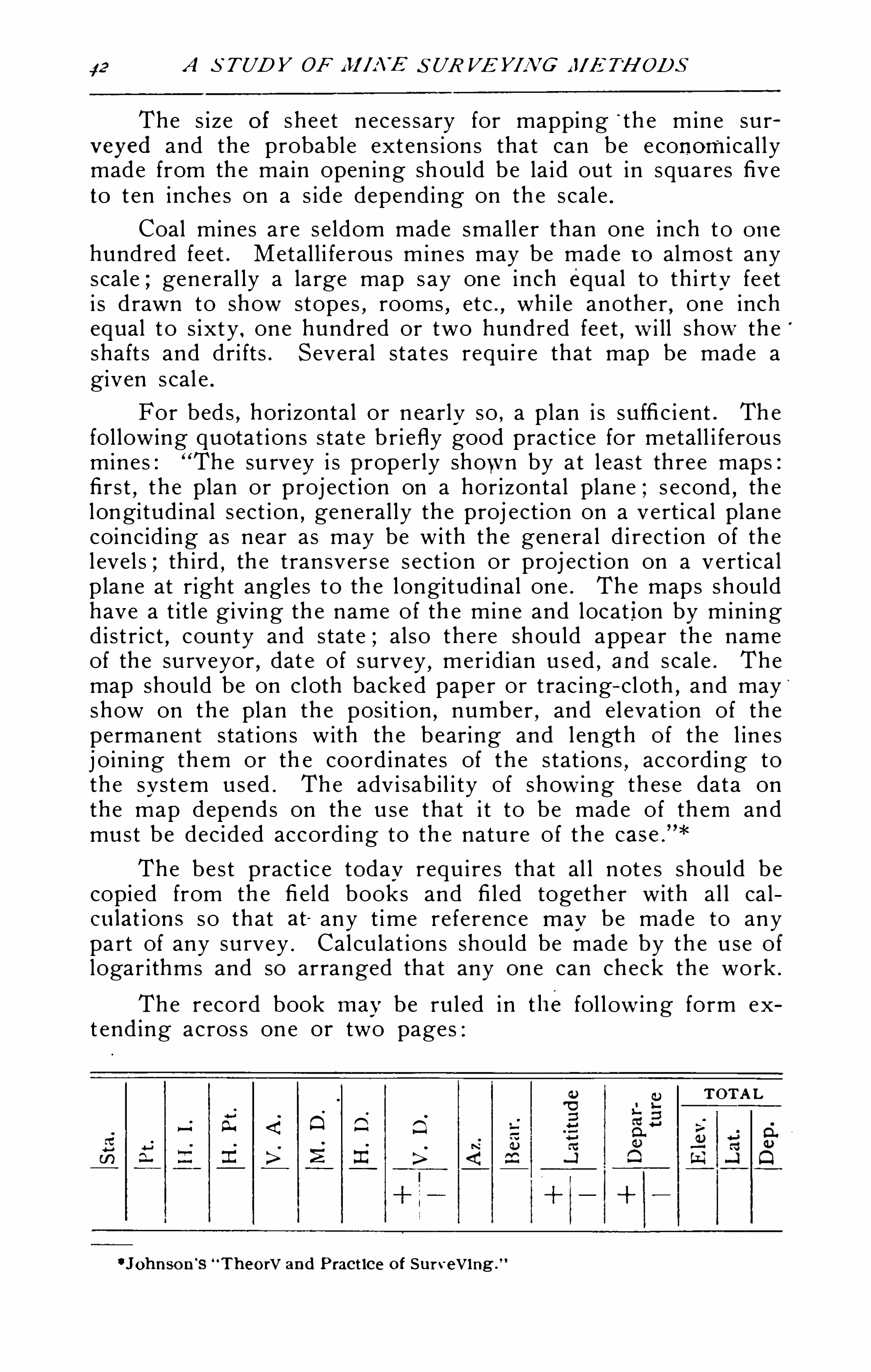
A S TUDY OF I I I I A'
E S UR VEYIN G I lI ETH ODS
The s ize of sheet neces sary for mapping“ th e mine sur
veyed and the probable exten s ion s that can be e conomi cal lymade from the main open ing should be la id out in squa res fiveto t en inche s on a s ide depending on th e scal e .
Coal mines a re s eldom made sma ll e r than one inch to one
hundred feet . Metal l i fe rou s mine s may be made t o almos t anyscal e ; gene ral ly a large map s ay one inch equal to th i rty fe eti s d rawn to show stopes
,rooms , etc . , wh il e another , one inch
equal t o s ixty . one hundred or two hundred fee t , w i ll show th e‘
shaft s and dri fts . Several sta t e s requ i re that map be made agiven scal e .
For bed s,horizontal or n early so , a plan i s su ffi c i ent . The
fol lowing quotat i on s s tat e b ri efly good pract i ce for metal l i fe rousmines : The su rvey i s proper ly shown by a t l eas t th ree maps :firs t
,th e plan or proj ect ion on a horizontal plane ; s econd , th e
longi tudinal s ect ion,general ly the proj ection on a verti ca l plan e
coincid ing as near as may be wi th th e genera l d i rect i on of th el evel s ; th i rd , th e transver s e s ect ion or proj ec ti on on a vert i ca lplane at right angl es to th e longitud inal one . The maps shouldhave a t i tl e giving th e name of th e mine and locat ion by min ingdi s t r ic t
,county and s tat e ; al so the re should appear th e name
of th e su rveyor,dat e of survey
,meridi an u s ed , and s cal e . The
map should be on cloth backed pape r or t rac ing- cloth , and mayshow on the plan th e posi t i on , number , and el evat ion of th epermanent s tat ion s with th e bearing and l ength of the l in e sj oin ing th em or th e coord inates of the s tat ions
,according to
the sys t em used . The advi sab il i ty of show i ng th es e data onthe map depends on th e u se that i t to be made of th em andmust be decided accord ing to th e natu re of th e
The bes t pract i c e today requ i re s that al l note s should becopied from th e fi eld books and fi l ed togeth er with al l ca lcu lat ions so that at any time re ference may be made to anypart of any su rvey . Calcu lat i on s should be made by th e u se oflogar i thms and so arranged that any one can check the work .
The record book may be rul ed in the fol low ing form ext end ing acros s one or two pages :
TOTA L
.
D.
A d
2 2;|H.
Pt
.
|H.
D.
v
‘ Johnson ‘s “Theory and Pract ice of Surveying .
A N D THEIR APPLICATIONS TO MINING ENGINEERING 43
Side' notes should be preserved in the fi eld book and may beinked i n i n orde r to make them mor e legible .
Certain s ch emes once adopted should be cont i nued . Aninspect ion of maps from var ious d i st r ic t s wi l l show how variedi s th e p racti c e . One company wil l place th e date of a surveyat t he las t s ta t i on made by that survey on each shaft andopen ing ; anoth er wi l l u se a l ett e r or number t o represent asu rvey ; anoth er wi l l u s e colors on th e maps
,a di s tingu ish ing
color for each su rvey . Pract i c e i n showing wo rked out groundi s even more vari ed . The common methods are as fol lows :(a) Prin t ing on the map th e phra se
“worked out -over suchport ions of th e min e ; (b) by coloring th e port ion s d ifferent fromthe perman en t open ings and pi l lars ; (c) by hatch ing th e boundari e s of worked out port ion s ; (d) by dott ing with inks .
Several o f th e la rge s t compan ies photograph thei r mapseach year in order t o keep a pe rmanent and convenient recordof the progres s . In such cas e s i t i s necessarv to mark eachyear ’s work so tha t i t wi l l sh ow on the plat .
Frequentl y min e maps must be produced in court a s ev i
id enc e . In a l l case s such maps should be s o comple te andso careful ly
,
p repared th at no quest i ons can ari se in regard toth e accuracy o f th e work of the enginee r . Special maps andd i agrams should be mad e on
.
a l arge scal e in order to bet te ri l lus trat e specifi c points i n ques t i on .
Mod el s may be made to show parts o f the mine , th e complete workings , and th e relat ive posi t ion of open ings . excavat ion s and property l in es . Model s should be on such a scal ethat d imensions can be read ily appreci at ed . Only open ingsmay be shown
,or
,th e ent i re te rri tory and ground included
may be repres ented by wood or g las s . Sed imentary deposi t sshould be repre sent ed by Sheet s o f gl as s or wood which canbe eas i ly handled and pl aced together to show actual cond i t ions . A skeleton of sh e et metal
,wire or tubing may rep re
sen t th e variou s openings . Sheet s of glas s may be u sed to
repres en t th e ve in s and excavations shown in colors on th eglas s
.Vert i ca l or hori zontal shee t s of glas s may be used and
a ft e r the shaft h as be en locat ed on th ese th e adj acent workingsmay be be proj ected .
CALCULAT ION OF VOLUMES AND ASSAY PLANS .
The est imation of volumes and tonnage of ore in placeor in stope s i s one of th e most important parts of a consul t in gengineer
’s work,and h e mus t adopt a syst em of work which
shal l be rapid and at th e same t ime sufli c i ently accurat e forh i s purpos e
.A good enginee r cannot be sat i sfi ed wi th any
th ing but absolute accu racy , but general ly suffi c i ent t ime i s
A S TUDY OF i i i /N E S UR VEY I A'
G i ll ETH ODS
not ava i labl e for th e most accurat e wo rk . Chapt er X I I I . of
Johnson ’s Su rveying i s given to a cons ide ration of th e mos taccu rat e methods for th e measurement of volumes , to wh ichwork the studen t i s referred . Pract ic i ng engi neers pe rs i sti n the us e of approximate methods , among wh ich th e mostpopular i s th e one known a s th e “mean end areas formula”
which Johnson condemns .
I n behal f of th e pri smoida l formula i ts ext reme accuracyi s urged
,whi l e i n beha l f o f th e mean ends formula i t s s im
pl i c ity and rapidi ty in u se a re undeni abl e . I n min ing worki t i s not pos s ibl e to ge t frequent cross s ect i on s . I n e st imat ingore bod i es , unbroken blocks la rger than 1 00
' x 1 00' should not
be con side red when i t i s known tha t th e ore body i s not regul a r . Winzes , ra i se s and dri fts s hould be dr iven to d iv id e th eore body into smal l blocks . Each mine has i t s spec ial probl emsand no fixed rul e can be st ated
,only th is , a lways underest i
mate the tonnage in blocks of ore . I n al l cas e s an accu rat emap
,about one inch to th i rty feet . s hould be u s ed and meas
urements of th e vei n and ore body taken every five fee t foraccurat e work . Such mea su rement s should b e noted on th emap at th e poi nt correspond ing to th e place wh ere th e measurements were taken . Samples should al s o be taken at th e sepoints . Methods of sampl i ng cannot b e di scus sed in th i s pape r .
A lmos t al l th e mines of th e Rand keep as say plans . An as sayplan of a mine i s any map
,— not neces sar i ly a plan ,
— whichshows accurate ly th e dimen sion s and valu e o f th e o re bod i e sa t such inte rval s a long dri ft s , wi nz e s , up rai s e s , shafts and s tope sthat an e st imat ion of th e valu e of the ore i n th e mine i s poss ibl e . Where th e cl ip i s s t e ep i t i s more conven i en t to u s eth e longi tud inal s e cti on
,becaus e th e l eve l s on th e plan would
be too clos e togeth er to al low th e figure s t o be d i s tin ct,but the
horizontal proj ect ion i s more general ly u sed becaus e th e sampl ing fol lows the i rre gula r i t i es of th e ve in wh ich do not appearon th e longi tudinal sect ion . The be s t p roj ect i on
,howeve r
,
i s that o f the ve in i ts e l f .Various t e rms are u sed in stat i ng th e amount of o re in
a m in e . Pract ice var i e s so much,however
,that i t i s not for
such a paper a s th i s t o revi ew what i s recommended in d ifferen tmin ing s ecti on s . T he recen t ed it ion of “The Sampl ing andE s t imat ion of O re i n a M in e” by T . A . R i ckard i s sugges tedfor a
,
care fu l s tudy of recent pract i ce .
The fol lowing terms are defined by variou s write rs :O re developed
,that whi ch i s acces s ib l e for measu remen t
,
sampli ng and ful l examina t i on on al l s id e s .
O re developing — ore expos ed on on e s id e , on two s id es ,or on th ree s ides .
O re expectant ,— that wh ich wi l l probably be exposed in
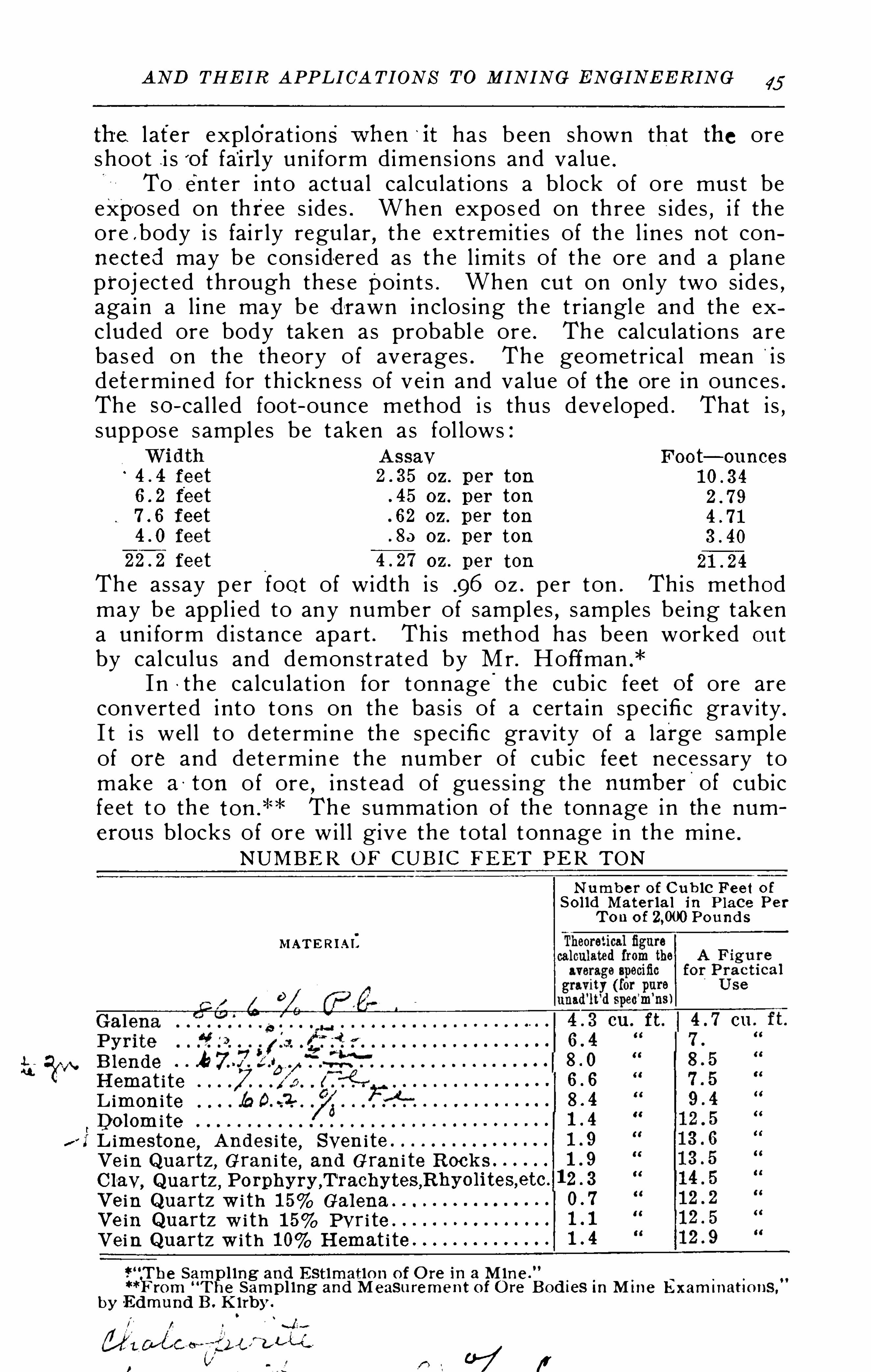
A N D THEIR APPLICA TIONS TO MINING ENGINEERING 45
th e l ater explorat ions when ‘
i t has b een shown that the oreshoot . i s '
of fai rly un i form dimens ions and value .
To ente r i nto actual calculat ions a block of ore mus t beexposed on three s ides . When expos ed on three s ides
,i f the
ore .body i s fai r ly regular , th e extremit i e s of th e l ines not connected may be cons ide red as th e l imit s of the ore and a plan eproj ect ed through thes e point s . When cu t on only two sides
,
agai n a l i ne may be d rawn inclos ing th e t r iangl e and the excluded ore body taken as probabl e ore . The cal culat ions arebas ed on the theory of averages . The geometr ica l mean i sdete rmined for th i cknes s of vei n and value of the ore in ounces .The so—cal l ed foot-ounce method i s thu s developed . That i s
,
suppos e s ampl es be t aken as fol lows :A ssay Foot—ounces
feet oz. per ton
feet 45 oz. per ton
feet 62 oz. per ton
fee t oz. per ton
feet oz. per ton
The assay pe r foot of width i s .96 oz . pe r ton . Thi s methodmay be appl i ed to any number of sampl es , s amples be ing takena un i form di s tance apart . Thi s method has been worked ou t
by cal culu s and demonst rat ed by Mr . Hoffman .
*
I n ~ th e calcu lat ion for tonnage'
th e cubi c feet of ore areconverted i nto tons on th e bas i s o f a certa in spec ific grav ity .
I t i s wel l t o dete rmin e th e spec ific gravi ty of a large sampl eof ore and dete rmin e the number of cubi c feet necessary tomake a tom of ore , i n s t ead of guess ing the number
'
of cubicfe et t o th e The summat ion of th e tonnage in th e numerou s blocks of or e wi l l give the total t onnage in th e mine .
N U M BER OF CUBI C FEET PER TON
N umbe r of C u bic F ee t ofSol id M a ter ia l i n Place Pe r
T on of Pound s
M ATERI A I:
cu ft cu
Blend e “ AH emat i teL imon i teDolom i te
/ I L imestone,A nd es i te
,Syen i te .
Ve in Quartz, Gran i te , and Gran i te Rock sC lay
, Qua rtz ,Ve in Quartz w i th 1 5% Galena .
Ve in Quartz w i th 1 5% Pyr i te .
Vein Quartz wi th 10% H emat i te” (Th e Samp l ing and Estimation of O re in a M ine .
0
**F rom “T h e Sampl ing and M easu rement of O re Bod i es i n M i ne Exam i nat ions ,
by Edmund B. K irby .
HHHHHHHHHo
N
l—‘HHOO
Q
OO
“S
H
-qwco
co
-ss
ua
mo
07 1'
A S TUDY OF M IN E JIETH ODS
The tonnage of coal in a tract may be s im i l arly es tim ated ,
i t bei ng unn ecessary to cons i der the analys is of th e coal A s
acre for a hori zontal bed . The spec i fi cgr avity o f the coal should be cons i dered when accura t e figu res
Loose ore pi l ed on dumps in pi eces fr om head to gravels i z e wi ll have from 35% to 50% of i nters ti ti al spac es
,th e per
centage be ing grea test i f th e lumps are somewhat equal s ized .
Thus a dump wi th 4055 of space s , and compos ed of ore averaging cubi c fe et per ton in place , wi ll measu re cubi c feetper ton
The mining engi n eer may be called to direct u ndergroundope rati on s of vari ous ki nds and in almos t every instance care fuland succes s ful work depends in a measur e upon g ood surveyi ngand mappi ng. Tunn el s for wat e r works
,submari ne tun nels,
submar in e pipe l i nes , etc .
, cal l for g ood maps and generall y th emi n ing man i s cal led upon to do th e work .
Such vari ed work requi r e s car e ful appli ca ti on to duty andatt enti on to detai ls which are o ft en negl ect ed in surface work .
M W ‘H BI BLI OGRAPH Y .
TEXT BOO K S ON SURVEY ING .
Brough—“M i n e Su rveyi ng.
Carhart—“Plan e Surv eyi ng. Chap VI I I .
Dav i es—“ Surveyi ng and Leveli ng.
” Book X , Sec . I I I , I V .
John son—“ Th eory and ! Practi ce of Surveying.
” Chap X I .
Luptonh“A Practi cal Treati s e on M i ne Surveyi ng.
”
Nugent—“Pl an e Surveyi ng. Chap XRaym ond—“Pl an e Surveyi ng Chap . X I I .
Sc ott and o th ers—“Mine Su rveyi ng Instru ment s . T AI . M . E .
L ;
PER IOD ICALSAbbrevi a t i ons
A . I . M E.
—Transa cti on s o f th e Ameri can Ins ti tu t e ofMin ing Engi neers .
A . S C . E —Tran sa c tions of th e Ameri can Soc i e ty of Civi lEng i n eer s .Col l Eng .
—Col li ery Engi neCol . S . S .
— P roc e edi ng s of th e Colo ra do Sc i en t i fi c Soc i e tv .
E . 8: M . J —Engi ne eri ng and M i n ing Journal .M M —M in es and Mi nera l s .M in . Rept—Mi nin g Repo rt e rS . of M . Q—Sc hoo l of M ines Q uart e rly
m’
g‘
gh e Samp l ing and Measu remen t of Ore Bod ies .
”K irby , Col . 3 EL Dec. 3, 1856.
AJ
ND THEI R A PPLI CA-TIONS TO MINING ENGINEERING 47
REFERENCES .
Bas e Lin eEs tabl i sh ing undergroundbase ‘l in e
,Col l . Eng . Vol . X IV , 92 .
S . of M . Q . Vol . X I , 333.
"
K i nd and weight of Col l . Eng . Vol . XV I , 31 .
S . of M . Q . Vol . X I, 333.
Carrying Merid ian into MineSee Connect ion s
,P lumbing , and Shaft s .
Connect ionsUnderground
,a t Leavenworth , A . I . M . E . Vol . XX IV
,25.
Through two or mo re shaft s , Col l . Eng . Vol . XV I , 53.
On mine road s,
M . M . Vol . XX I I I , 280 .
D epth of Sha ftMeasu ring ,
Col l . Eng . Vol . XV I , 53Incl ined ShaftsCorrect i on s for e rrors in , M . M . Vol . X IX , 433.
Measuri ng through crookedshafts w i th plumb l in e
,S . of M . Q . Vol . XV I
,146 .
Survey ing,withou t a ttached
te l e scope,
Col l . Eng . Vol . XV I , 31 .
Improved form of plummet , A I . M . E . Vol . I I I , 39.
P lumbing , of Sha fts ,Hoosac tunnel method .
Comstock Lode method ,
Montana method .
Croton Aqueduct method ,Severn Tunnel method
,
Sperry method ,Tamarack sh aft
,
I n i ron mine s -in Pa .,Gen eral method s
,
Stat ion sIn poor roof , M . M . Vol . X IX ,
247 .
Surveying Method sGenera!,
Col l . Eng . Vol . X IV , 1 0, e tc .
In“
coa l fi elds of Pa . ,Coll . Eng . Vol . X IV ,
197 , etc .
I n i ron mine s o f Va . ,A . I . M . E . Vol . XX , 96 .
In th e Rocky Mountain s,
M . M . Vol . X I‘X ,24 1 .
Col l . Eng . Vol . XV I , 52 .
E . M . J . Vol . LV , 81 .
E . M . J . Vol . LV , 79 .
A . S . C . E . V01 XX I I I , 22 .
S . of M . Q . Vol . I I I , 272 .
A . I . M . E . Vol . XX IV ,29 .
M . M . Vol . XX I I , 247 .
A . I . M . E . Vol . VII , 1 39 .
A 1 M . E Vol . XX I , 792 .
E . M . J . Vol . LXX IV , 478.
E . M . J . Vol . Lxxxv , 749 .
Col l . Eng . Vol . X IV , 92 .
Col l . Eng . Vol . XV I , 31 .
M . M . Vol . X I X ,187 .
A S TUDY OF M IN E S UR VEYIN G M ETH ODSTele scopeAdj ustment of s ide
,A . I . M . E . Vol . XX IV ,
28.
VolumeMeasurement of s topes , Col . S . S . D ec . 3,
1895.
O f smal l dr i ft s and stopes , M . M . Vol . XX I , 344 .
WiresK
’i nd and s iz e of wires ,
I l luminat ing ,
I nspect ion of wi res,
Locat ion of fou r or more ,Prevent ion o f v ibrat lon ,
Suspens ion of wire s ,
PROBLEMS .
The fol l owing are sugges ted i n o rder to teach the s tuden tgraphical and t r igonometri c methods for solv ing min e surveying probl ems .
Problems involving desc ript iv e geomet ry t o dete rmine theint ers ect ion s of ve in s
,th e locat i on o f open ings to cu t intersec
t i ons of ve in s and to locat e open ings when ve ins are fau lted .
I n al l cas es c erta i n as sumpt i on s mus t be made :a . Excep t i n problems 4 and 8, th e sur face i s a s sumed to
be a horizontal plan e .
b . Vein s are as sumed to be plan es of un i form dip . I ntersec
t ions of v e ins a re as sumed to be s t ra ight l i ne s . Except i n “b”
of Prob . 3, th i cknes s o f ve in s i s not con s ide red .
c . Shaft s on vein s wi l l b e s tra igh t bu t incl in ed .
d . Except'
where th e grade i s specifi ed tunnel s are as sumed hori zontal , al so dri ft s .
e . D imens ions of shafts and tunnel s should not be cons idered , t hat i s , open ings are cons ide red to be s traight l in es .
f . A l l i ncl in ed shafts to b e the shor tes t pos s ibl e excepti n Prob . 8.
I n th e solut ion of import ant p roblems found in pract i ce ,the s cal e u sed should be such that th e errors of plott i ng do notmat erial ly change th e resu lt s .
PROBLEM I .
a . Locate vert ica l shaft on . l in e a—b t o cu t th e intersect ion of vein s . Find depths of sh aft and di s tance on “
a-b from
Col l . Eng .
‘
Vol . XV I , 32 .
S . of M Q . Vol . X I , 333.
C011. Eng . Vol . X IV , 92 .
C on. Eng . Vol . XVI , 32 .
Coll . Eng . Vol . X IV, 92 .
Coll . Eng . Vol . X IV, 92 .
S . of M . Q . Vol . I I I , 27 1 .
Col l . Eng . Vol . XVI , 31 .
Col l . Eng . Vol . X IV , 92 .
A S TUD Y OF !WINE S UR VEY/Aft? AI ETH ODS
PROBLEM 6 .
a . On th e Lotu s 200' N W from “
0” an incl ined sh a ft i s
sunk 300’ i n l ength . From the bot tom o f sha ft a dr i ft extends
on ve in N 75° W . A t what d i s t ance from shaft should a cross
cut be s ta rt ed to cut i nt e rs ec t ion of Royal and Minnesota . Thi sc rosscu t to be at rt . angl e s to dri ft . Find l ength of cros scut .
D raw to scal e Take G E &W th rough o”
PROBLEM 7
a . Locate ve rt ica l sha ft to cut in t e rsect ion of ve ins . Findbearing and d i stance from
b . Vert ica l sha ft i s sunk at x’ to depth of shaft i nA t bot tom of shaft cross cu t i s run to cu t th e int ers ect ion ofve ins . Find bear ing and l ength o f cros scut .
c . Incl in e s ta rt ed. at x’ to cu t i nt e rs ect ion of ve in s . Findl ength , p i tch and bearing .
(1 . Locate incl in e s on : Gopher,Mt . Boy and Y uma , to
cu t i nt ers ect ion of ve in s . Find lengths,d is tance s and bearings
( I 3,from oD rawt o s cal e 1 Take G E W through “
07 ,Poin t x ’ i s N 30
° W from 0
C‘
PROBLEM 8.
M a . From “0 outcrop bears N 1 0
° E and di p of ve in i s 45°
800 up the h i l l th e po int ‘ ”0" has an el evat i on 300
’ h igher thanFind s t rike of vein .
b . From 0” sha ft i s sunk on vein . From “
0” tunne l
i s dr iven on vei 10
1 . Find poin t o f in t ersect i on and length s ofshaft and tunnel . Shaft p erpendic ula r to out crop .
s h i ke
D raw to scal e Take G E W .
f l!? o ut c r op .
goo -f f . é oP /z ofr fa/ d /s f’
.Ow‘
cmp S fr / i a ‘
PROBLEM 9 .
a . Find poin t to s ink by bear ing and d i s t . from “o” tocut in t e rsect i on of ve in s . Cal l po int “x” Find depth .
b . A t x”, due wes t o f o”
51 00 , S 67°
45’ W 7850
'
from“0” ve rt i ca l dr i l l hol e s a re put down cutt ing a faul t plan e at :
1000’
1000’ resp . I t has been determined that port ion
above fau l t plan e has moved perpend i cular to s tri ke in a southeas te rly d i rect ion a long faul t plan e Find poin t to s i nka s in a Faul t ing took place
,th en count ry e roded to pre s ent
l eve l cond i ti on .
D raw to scal e Take G E W through

A N D.
TH EIR A PPLICA TIONS TO M INING ENGINEERING 51
PROBLEM 10.
a . On in ters ect ion of P i l o t and Mary incl in ed shaft i s downOn inters ect i on of
.
O rphan N o . I and O rphan N O . 2
inc l i ned shaft i s down A s the air i n both place s i s bad,we
wi sh to s tart an incl in ed upra i s e from one shaft to connect wi ththe other ; th i s connect ion to be th e shorte s t poss ib l e . Locatepoint s i n both shafts so work may be carri ed on at both ends .
Find length , pi t ch and bearing of the connect i on . Revers et race s on O rphan 1 and 2 . Compare .
D raw to scal e Take G E W throughPROBLEM 1 1 .
A ve in d ips an entry is driven N 40° W in th e ve in on a
5% grade .
‘ What i s th e s t r ike o f th e vein ?
PROBLEM 1 2 .
A dri ft on a 3% grade i s d riven N 40°
E i n a ve in whoses trike i s N 60° E . Requ ired. th e cl i p o f th e vei n .
PROBLEM 1 3.
A ve in d ip s 45° to the wes t and s trike s N E . A dri ft
on the ve in i s driven N E . Requ i red the grade of thedri ft .
PROBLEM 14 .
A ve in d ips 54° to th e eas t and s tr ikes N W . What
i s th e bear ing of a dr i ft on the vei n driven on a 3% grade ?
PROBLEM 15.
I . The s trik e of a ve i n d ipp ing to the S . W . 75° i s S
E . From a given poin t o f outcrop , e levat ion the mouthof a tune l bears S W and d is tant 3000
’on a vert i cal
angle of The tunne l i s dr iven straight , horizontal andN E .
rljfi équ ired th e d is tanc e from the mou thg of thetunnel to the point at wh ich i t into s e ct s th e ve in . 1 1 3 As sumeth e tunne l on a 2% grade . i 114 ) ? hat i s the shorte s t d i s tancefrom the tunnel porta l to th e vein ? Art
PROBLEM 1 6 .
A vein (a) d ips 55° to th e northwest and s trikes N E .
A s econd vein (b) s tr ikes N E and on the surface (assumed to be level) i s d i stan t from th e (a) vein How far fromth e ve in (a) should a vert ical shaft be put down to pi erce thein ters ect ion of th e ve ins ( 1 ) i f (b) d ips 30
° t o the northwest ; (2)i f (a) d ips 75
° t o th e southea s t and (b) 55° to th e northwe s t .
Wh at wi l l b e the depth o f sha ft i n al l cas es ?

A S TUD Y OF i ll /A’E S UR VEYIN G 1 1!ETH ODS
PROBLEM 1 7 .
A vein d ips 43° t o the northwe st
,s t r ikes N E
,e=l eva ~
t ion of out crop A t an el evat ion of and d i s tantfrom the outcrop an incl ined shaft d ipp ing 75
° and beari ng N W is sunk to inte rs ect th e ve in . (a) Requ i red th edepth t o wh ich th e shaft must b e sunk . (b) A s sum e th e p it chof the sha ft the same but the bearing S W ; what wi l l be
!th e depth of sha ft ?
PROBLEM 18.
The surface has a un i form s lope of 1 0° to th e north . Ave in str ike s eas t and west and d ips 40
° t o the north .
(a) How fa r north of th e outcrop must one go to s ink a
ve rt i cal sha ft wh ich shal l cu t th e ve in at a depth of (b)What wi l l b e th e bearing of dr i ft s on th e ve in driven from th ebottom of the sha ft on a 3% up grade ? (c) How far can th eybe driven so as not to approach nearer than 1 00
’ t o the surface ?
PROBLEM 1 9 .
The vein described i n problem 1 8 i s i n t e rs ec ted a t a depthIn 1 000
’ by a ve rt i ca l sha ft . From the bottom of th e shaft as lope on the ve in extends du e north An ent ry i s d r ivenon a 4% grade to the southwes t from the bo ttom of the s l opefor a d i s tanc e of Requ i red the depth of v ert ical shaftn ecessary i n order to connect the end of th e ent ry wi th th esu rface ?
PROBLEM 20 .
The hori zontal d i s tance be tween two vert i cal shaft s i st he d ifference in e l evat ion of th e col la rs of shaft s i s Th edepth of sha ft sunk from the h igher point i s from thebottom of th i s shaft a c rosscu t (a) i s d r iven towards th e oth e rsha ft on a 1 % grade
,The second . shaft i s 350
’ deep . Re
qui red th e l ength and grade o f crosscut (b) from th i s sh aft tomee t th e breas t o f (a) .
Suppos e tha t the lower shaft de s cri bed i n 20 bears SW of th e othe r and that the c ross cut (a) i s d r iven S 40
° W . Re
qui red th e d irect ion,grade and len gth of (b) .
PROBLEM 2 1 .
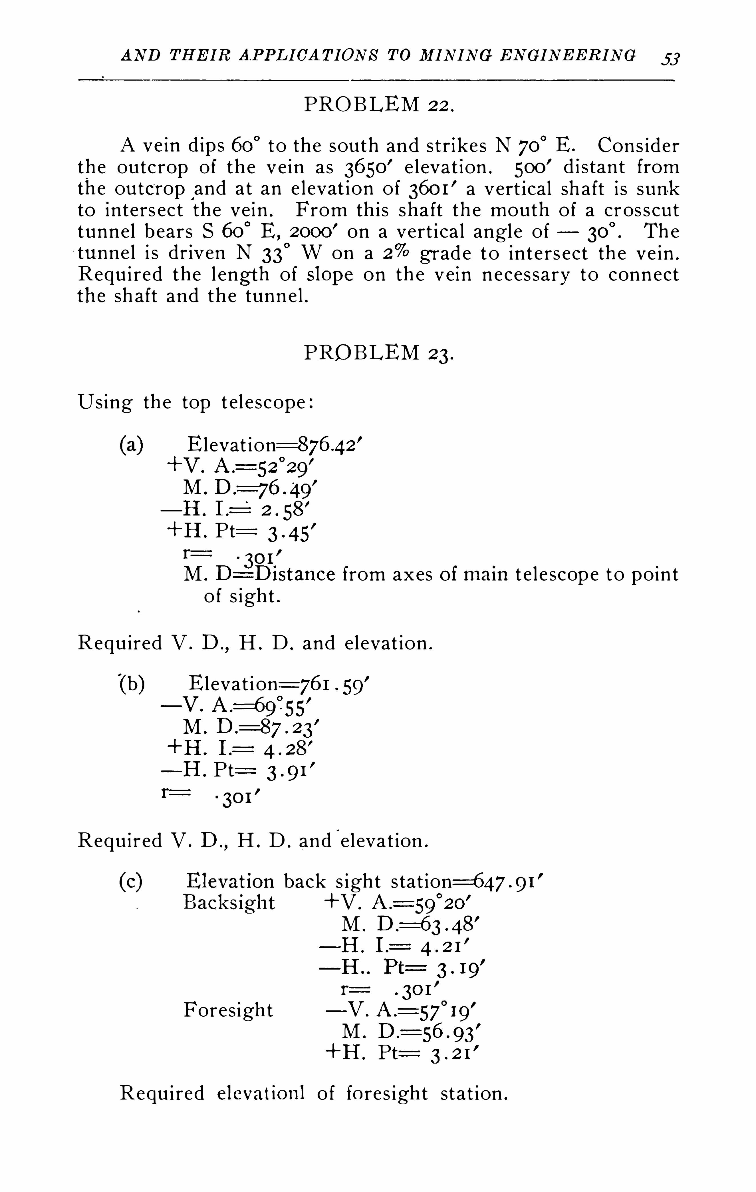
AN D TH EIR APPLICA TIONS TO M INING EN GINEERING 53
PROBLEM 22 .
A ve in d ips 60° to the south and s t rike s N 700 E . Cons ider
the outc rop of th e ve in as 3650’ e l evat ion . 500
’ d i s tant fromthe outcrop and at an e l evat i on of 360 1
’ a vert ical sh aft i s sun-kto inters ec t the vein . From th i s sha ft th e mouth of a cros s cuttunnel bears S 60°
E ,2000
’ on a vert i ca l angl e of Th etunne l i s driven N 33
° W on a 2% g rade t o in t e rs ect th e ve in .
Requ i red the l engt h of mpe on th e vein neces sary to connectthe sh aft and th e tunnel .
PROBLEM 23.
Using th e top t el e scope :
Elevat i on=876 .42’
+V .
M .
—H . I .-l 2 . 58
’
+H . Pt:. 30 1
’
M . D=Di stance from axes t e l e scope to poin to f s ight .
Requ ired V . D. , H . D . and el evat ion .
(b) Elevat i on=76 1 59’
—V . A .=
M .
+ 11 .
—H . P t:nz z
. 301’
Requ i red V . D. ,H . D . and
”
el eva t ion .
Foresigh t
Requ i red e levat ionl of fo res igh t sta t ion .
back s igh t s tat ion=647+V .
M .
—H . I .=
—H Pt:
. 30 1—V . A .
=57 19M . D.
+H . Pt:
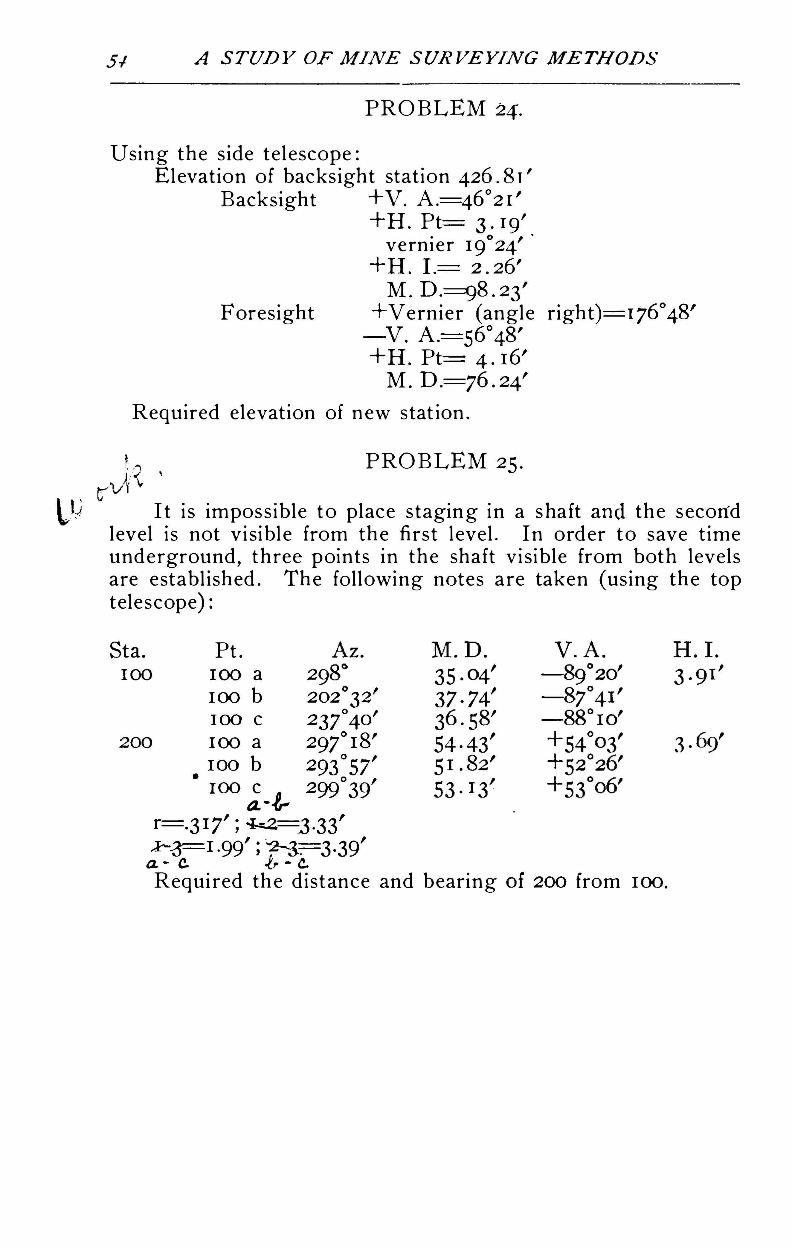
PROBLEM
Using the s ide t e l e scope :E l evat ion of backs igh t stat i on
Backs igh t +V .
+H . Pt:vern i er
+H . I .
M .
Fores ight +Vern i e r (angl e righ t)—V .
+H . Pt:M . D.
Requ i red el evat ion of n ew stat ion .
PROBLEM 25.
I t i s impos s ibl e t o place s tagin g i n a s ha ft and th e s econdl evel i s not v i s i bl e from th e fi rs t l eve l . I n order t o save t imeunderground
,th ree poin ts i n th e shaft v i s i bl e from both l eve l s
are e stabl i sh ed . The fo l l owing no te s a re taken (us ing th e toptele s cope) :
P t .1 00 a 2
1 00 b1 00 c 237
°
4o’
1 00 a100 b 293257
’
1 00 c 2
4-8
99 39
-99 9’
a. 0.
Requ i red th e d i s tance and bearing 200 from
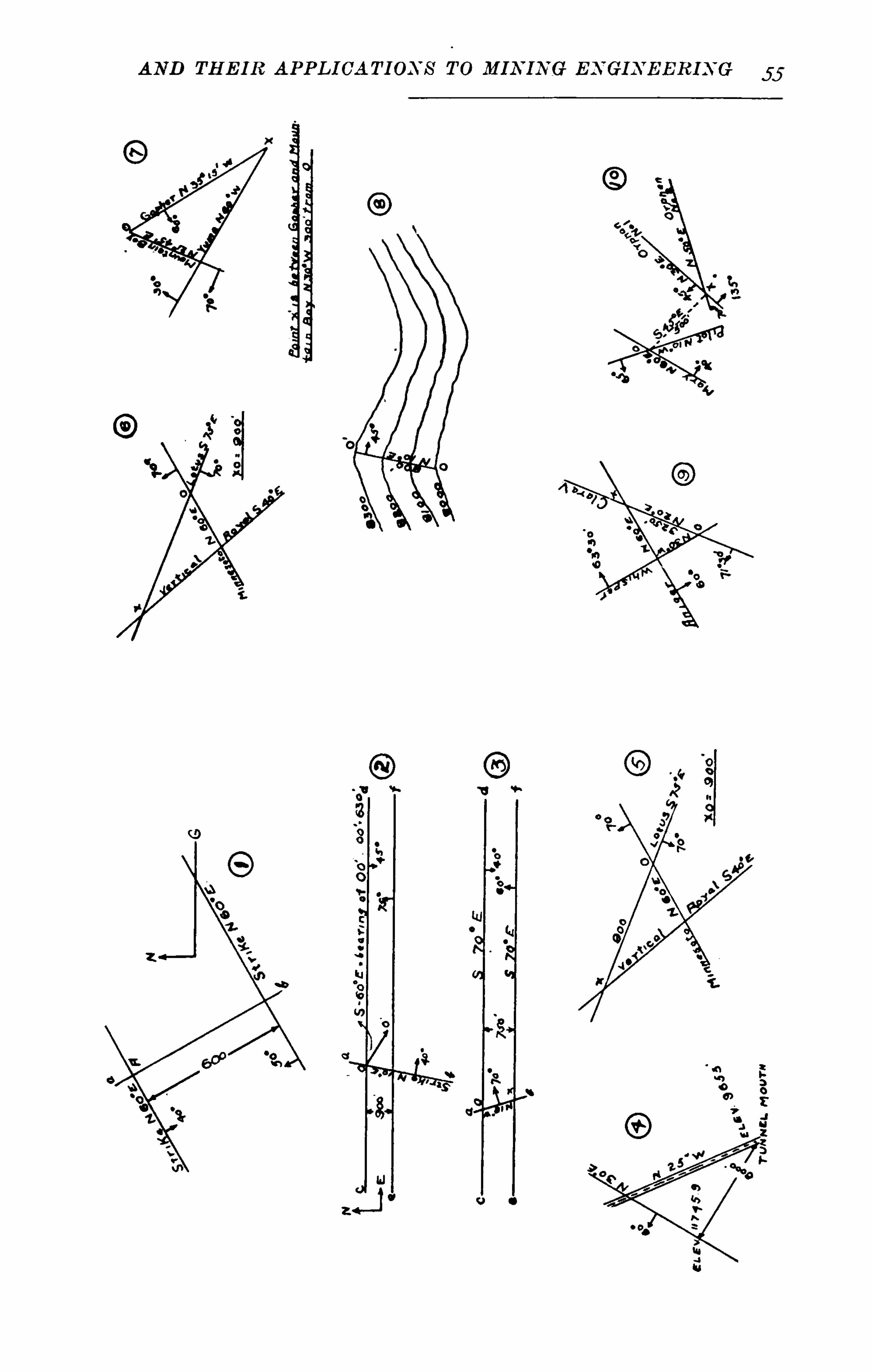

T ABLE OF CONT ENT S
In troduction
Defin i t ion s .
Impor tance of M i ne S urvey i ngDiffi culties .
N otes on H istory ofMi n e surv ey i ng .
In struments and Equipment Used .
S urv ey ing Pa rty .
Unde rg round S ta t ions .
Ba se Line .
C a rry ing the Leve l an d Me r id ia n Into th e M i ne . .
Unde rg roun d T rave rs ing .
S urv ey ing the M ine . .
Geog nosy ”
S urv ey ing Dr i llHele s ”Loca ting Openi ng s andMine Plant .S ha f t S in k ing . .
T unne l ing .
M ine Work i ngs
C urves and C onnec t ion s
Open ing s to Inte r s e c t
Geolog i c a l I rreg ular i t i e s
Dra inage .
Haul ag e
Mapp i ng and Mode l s .
C a lcula ti on of Volumes and A s s ay P l an s .
Problems
Bi b l iog raphy .
Recommended