EtherNet/IP: Industrial Protocol White Paper © Institute of Electrical and Electronic Engineers, EFTA 2001 By Paul Brooks European Marketing Manager, Logix/NetLinx Technology Adoption Rockwell Automation October 2001
Abstract – DeviceNet™ and ControlNet™ are two well-known industrial networks based on the CIP protocol (CIP = Control an Information Protocol). Both networks have been developed by Rockwell Automation, but are now owned and maintained by the two manufacturer's organizations ODVA (Open DeviceNet Vendors Association) and ControlNet International. ODVA and ControlNet International have recently introduced the newest member of this family – EtherNet/IP ("IP" stands for "Industrial Protocol"). This paper describes the techniques and mechanisms that are used to implement a fully consistent set of services and data objects on a TCP/UDP/IP based Ethernet® network.
I. Introduction Automation architectures must provide users with three primary services. The first, control, is the most important. Control services involve the exchange of time-critical data between controlling devices such as PLCs and I/O devices such as variable speed drives, sensors and actuators. Networks that are tasked with the transmission of this data must provide some level of priority setting and/or interrupt capabilities. Second, networks must provide users configuration capabilities to set up and maintain their automation systems. This functionality typically involves the use of a personal computer (PC) or equivalent tool for programming of various devices in the system. This can be performed at commission, and also during runtime, such as recipe management in batch operations. Lastly, an automation architecture must allow for collection of data for the purposes of display in MMI stations, analysis and trending, and/or troubleshooting and maintenance. Networks that can provide all three services – control, configuration, and collection of data – deliver the greatest amount of flexibility and efficiency for better overall system performance. Networks that are based on the producer/consumer model – where data is identified, rather than tied to explicit source and destination addresses – can support control, configuration, and collection of data services. Application layers using distributed objects and producer/consumer communication services meet the requirements of automation architectures. In providing these services (Figure 1 shows a typical automation architecture), it cannot be assumed that a single network level will meet all application requirements as each network's physical and data link layers have their own attributes and benefits. Where a multi-level network structure is required, then the network architecture must provide consistency of data between disparate network segments.
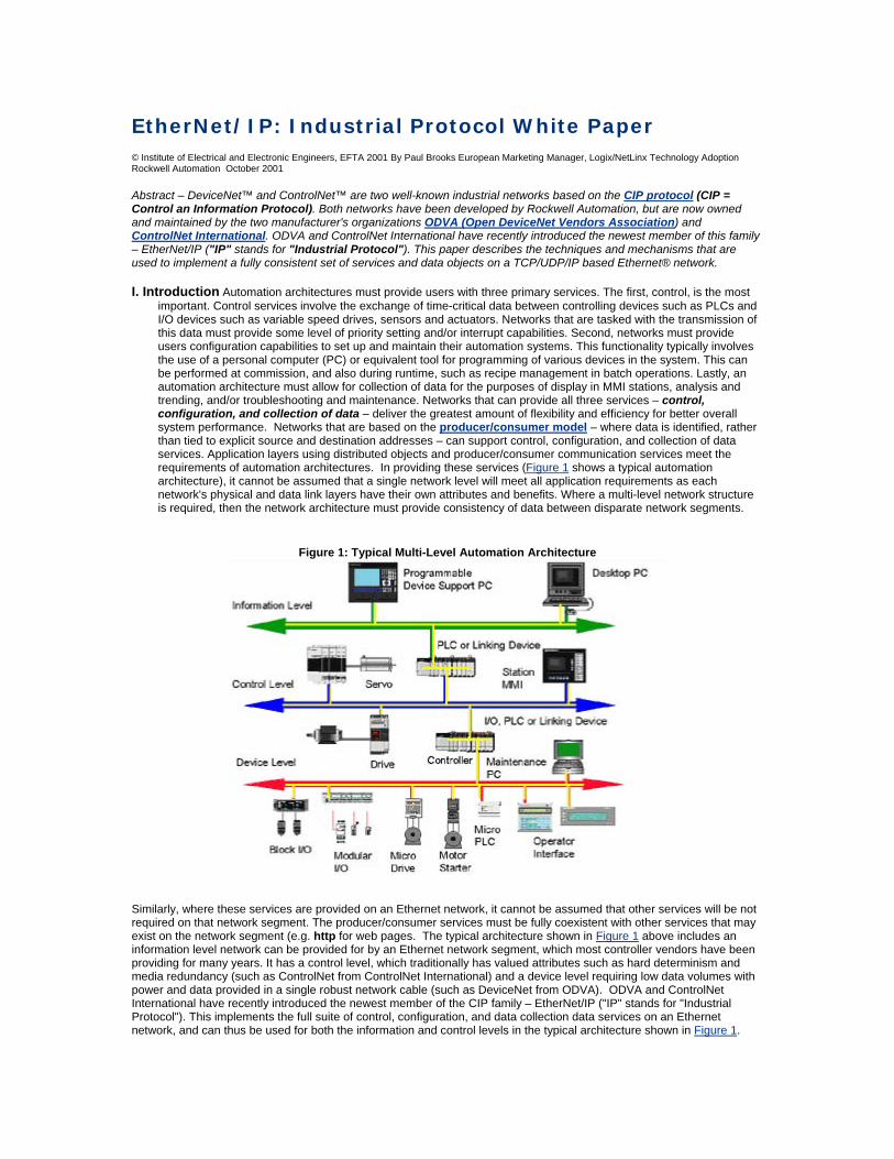
Figure 1: Typical Multi-Level Automation Architecture
Similarly, where these services are provided on an Ethernet network, it cannot be assumed that other services will be not required on that network segment. The producer/consumer services must be fully coexistent with other services that may exist on the network segment (e.g. http for web pages. The typical architecture shown in Figure 1 above includes an information level network can be provided for by an Ethernet network segment, which most controller vendors have been providing for many years. It has a control level, which traditionally has valued attributes such as hard determinism and media redundancy (such as ControlNet from ControlNet International) and a device level requiring low data volumes with power and data provided in a single robust network cable (such as DeviceNet from ODVA). ODVA and ControlNet International have recently introduced the newest member of the CIP family – EtherNet/IP ("IP" stands for "Industrial Protocol"). This implements the full suite of control, configuration, and data collection data services on an Ethernet network, and can thus be used for both the information and control levels in the typical architecture shown in Figure 1.
II. CIP Implementation On Ethernet The EtherNet/IP Specification is available for free download from the ODVA and ControlNet International web sites in addition to the EtherNet/IP website. Apart from being subdivided into several chapters and appendices, the following features are described in the document:
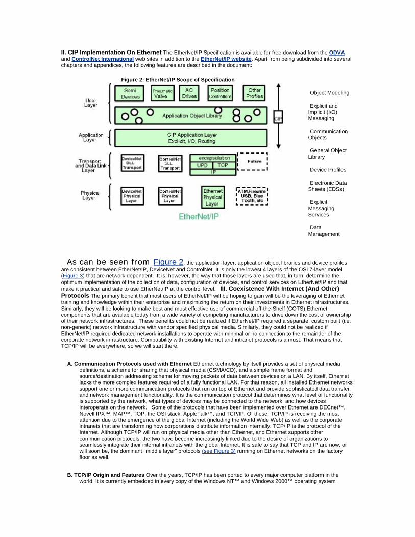
Figure 2: EtherNet/IP Scope of Specification
Object Modeling
Explicit and Implicit (I/O) Messaging
Communication Objects
General Object Library
Device Profiles
Electronic Data Sheets (EDSs)
Explicit Messaging Services
Data Management
As can be seen from Figure 2, the application layer, application object libraries and device profiles are consistent between EtherNet/IP, DeviceNet and ControlNet. It is only the lowest 4 layers of the OSI 7-layer model (Figure 3) that are network dependent. It is, however, the way that those layers are used that, in turn, determine the optimum implementation of the collection of data, configuration of devices, and control services on EtherNet/IP and that make it practical and safe to use EtherNet/IP at the control level. III. Coexistence With Internet (And Other) Protocols The primary benefit that most users of EtherNet/IP will be hoping to gain will be the leveraging of Ethernet training and knowledge within their enterprise and maximizing the return on their investments in Ethernet infrastructures. Similarly, they will be looking to make best and most effective use of commercial off-the-Shelf (COTS) Ethernet components that are available today from a wide variety of competing manufacturers to drive down the cost of ownership of their network infrastructures. These benefits could not be realized if EtherNet/IP required a separate, custom built (i.e. non-generic) network infrastructure with vendor specified physical media. Similarly, they could not be realized if EtherNet/IP required dedicated network installations to operate with minimal or no connection to the remainder of the corporate network infrastructure. Compatibility with existing Internet and intranet protocols is a must. That means that TCP/IP will be everywhere, so we will start there.
A. Communication Protocols used with Ethernet Ethernet technology by itself provides a set of physical media definitions, a scheme for sharing that physical media (CSMA/CD), and a simple frame format and source/destination addressing scheme for moving packets of data between devices on a LAN. By itself, Ethernet lacks the more complex features required of a fully functional LAN. For that reason, all installed Ethernet networks support one or more communication protocols that run on top of Ethernet and provide sophisticated data transfer and network management functionality. It is the communication protocol that determines what level of functionality is supported by the network, what types of devices may be connected to the network, and how devices interoperate on the network. Some of the protocols that have been implemented over Ethernet are DECnet™, Novell IPX™, MAP™, TOP, the OSI stack, AppleTalk™, and TCP/IP. Of these, TCP/IP is receiving the most attention due to the emergence of the global Internet (including the World Wide Web) as well as the corporate intranets that are transforming how corporations distribute information internally. TCP/IP is the protocol of the Internet. Although TCP/IP will run on physical media other than Ethernet, and Ethernet supports other communication protocols, the two have become increasingly linked due to the desire of organizations to seamlessly integrate their internal intranets with the global Internet. It is safe to say that TCP and IP are now, or will soon be, the dominant "middle layer" protocols (see Figure 3) running on Ethernet networks on the factory floor as well.
B. TCP/IP Origin and Features Over the years, TCP/IP has been ported to every major computer platform in the world. It is currently embedded in every copy of the Windows NT™ and Windows 2000™ operating system
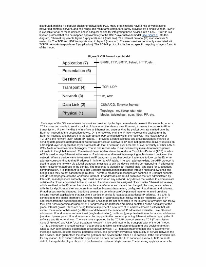
distributed, making it a popular choice for networking PCs. Many organizations have a mix of workstations, networked printers, servers, and mid-range and mainframe computers, rarely provided by a single vendor. TCP/IP is available for all of these devices and is a logical choice for integrating these devices into a LAN. TCP/IP is a layered protocol that can be mapped approximately to the OSI 7-layer network model (see Figure 3). On this diagram, Ethernet represents layers 1 (physical) and 2 (data link). The Internet protocol (IP) maps to layer 3 (network). The TCP and UDP transports map to layer 4 (transport). The user services commonly associated with TCP/IP networks map to layer 7 (application). The TCP/IP protocol suite has no specific mapping to layers 5 and 6 of the model.
Figure 3 OSI Seven Layer Model
Each layer of the OSI model uses the services provided by the layer immediately below it. For example, when a TCP connection needs to send a packet of data to another device over Ethernet, it passes the packet to IP for transmission. IP then handles the interface to Ethernet and ensures that the packet gets transmitted onto the Ethernet network to the destination device. On the receiving end, the IP layer receives the packet from the Ethernet interface and passes it to the appropriate TCP connection within the receiver. The lowest layer of TCP/IP is the network layer, where IP resides. IP provides a connectionless and unacknowledged method of sending data packets (datagrams) between two devices on a network. IP does not guarantee delivery; it relies on a transport-layer or application-layer protocol to do that. IP can run over Ethernet or over a variety of other LAN or WAN (wide area network) technologies. That is one reason why IP can seamlessly move data from corporate intranets to the global Internet. The network layer is also where the Address Resolution Protocol (ARP) resides. ARP is used to map Ethernet addresses to IP addresses and to maintain mapping tables in each device on the network. When a device wants to transmit an IP datagram to another device, it attempts to look up the Ethernet address corresponding to that IP address in its internal ARP table. If no such address exists, the ARP protocol is used to query the network via a local broadcast message to ask the device with the corresponding IP address to return its Ethernet address to the sender. The response is placed in an internal table, and used for subsequent communication. It is important to note that Ethernet broadcast messages pass through hubs and switches and bridges, but they do not pass through routers. Therefore broadcast messages are confined to Ethernet subnets, and do not propagate onto the worldwide Internet. IP addresses are 32-bit quantities that are administered by InterNIC, an independent authority, and must be unique on any network. Any device that wishes to communicate outside of a closed corporate LAN must use an IP address from the assigned block. Unlike Ethernet addresses, which are fixed in the Ethernet hardware by the manufacturer and cannot be changed, the user, in accordance with the local policies of their corporate Information Systems department, configures IP addresses and subnets. IP addresses may be changed, but doing so must be done in a carefully planned manner to avoid breaking existing network applications that assume a particular device is located at a particular IP address. If a LAN is connected to the global Internet via a router, then its IP addresses must follow the rules regarding use of IP addresses from the assigned block. Corporate LANs that are not connected to the Internet at any point can follow their own rules regarding assignment of IP addresses. IP addresses are being depleted as the popularity of the global Internet grows. Steps are being taken to implement a new form of IP address (known as IPv6) that will extend the number of bits used (to 48 bits) and therefore the number of IP addresses available. Like Ethernet addresses, IP addresses can be unicast (single destination), multicast (group destination) or broadcast addresses (received by everyone). IP addresses must be mapped to the proper supporting Ethernet address type by the IP software and Ethernet driver. The transports supported by the TCP/IP protocol suite are TCP (Transmission Control Protocol) and UDP (User Datagram Protocol). They both map to the transport layer of the OSI model. TCP is a connection-oriented transport that provides reliable transmission of data from one device to another. Once a TCP connection is established between two devices, TCP handles fragmentation and re-assembly of message packets, detects failures, performs retries, and generally provides a high quality of service between the two devices. TCP guarantees the data will get from one device to the other if it is possible. If the transmission fails for any reason, TCP ensures that the applications on both ends of the TCP connection know it. TCP presents data to the application layer above it in the form of a continuous byte stream. The receiving application must be
capable of recognizing any message delimiters that might be embedded in the byte stream by the transmitting application. TCP works only in unicast (point-to-point) mode, and is used by applications such as Telnet (terminal emulation), FTP (File Transfer Protocol), and HTTP (Web Server). In an industrial automation application, TCP is typically used to download ladder programs between a workstation and a PLC, for MMI software that reads or writes PLC data tables, or for peer-to-peer messaging between two PLCs. UDP is a much simpler transport protocol. It is connectionless and provides a very simple capability to send datagrams between two devices. It does not guarantee that the data will get from one device to another, does not perform retries, and does not even know if the target device has received the data successfully. Application layers that implement their own handshaking or connection management between two devices and, therefore, only need a minimal transport service, use UDP. For instance, UDP is used by applications such as SNMP and NFS. UDP is smaller, simpler and faster than TCP due to its minimal capabilities and use of resources. UDP can operate in unicast, multicast or broadcast mode. In an industrial automation application, UDP is typically used for network management functions, applications that do not require reliable data transmission, or applications that are willing to implement their own reliability scheme, such a flash memory programming of network devices. The protocols and applications that comprise the TCP/IP protocol suite are all documented in Request for Comment (RFC) documents that are maintained by the Internet Engineering Task Force (IETF). The IETF is an independent organization that acts as a standards organization for Internet protocols. The RFCs are open and are distributed freely, and can be obtained without charge from the IETF WebsiteI.
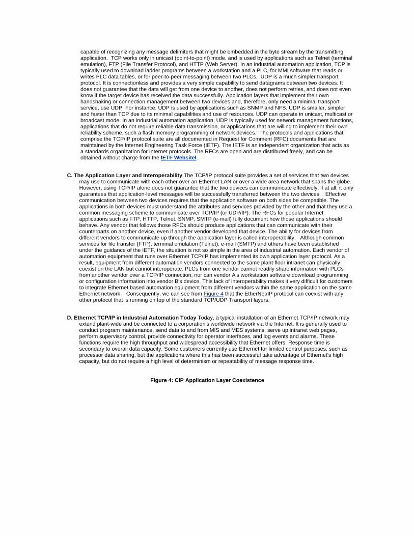
C. The Application Layer and Interoperability The TCP/IP protocol suite provides a set of services that two devices may use to communicate with each other over an Ethernet LAN or over a wide area network that spans the globe. However, using TCP/IP alone does not guarantee that the two devices can communicate effectively, if at all; it only guarantees that application-level messages will be successfully transferred between the two devices. Effective communication between two devices requires that the application software on both sides be compatible. The applications in both devices must understand the attributes and services provided by the other and that they use a common messaging scheme to communicate over TCP/IP (or UDP/IP). The RFCs for popular Internet applications such as FTP, HTTP, Telnet, SNMP, SMTP (e-mail) fully document how those applications should behave. Any vendor that follows those RFCs should produce applications that can communicate with their counterparts on another device, even if another vendor developed that device. The ability for devices from different vendors to communicate up through the application layer is called interoperability. Although common services for file transfer (FTP), terminal emulation (Telnet), e-mail (SMTP) and others have been established under the guidance of the IETF, the situation is not so simple in the area of industrial automation. Each vendor of automation equipment that runs over Ethernet TCP/IP has implemented its own application layer protocol. As a result, equipment from different automation vendors connected to the same plant-floor intranet can physically coexist on the LAN but cannot interoperate. PLCs from one vendor cannot readily share information with PLCs from another vendor over a TCP/IP connection, nor can vendor A's workstation software download programming or configuration information into vendor B's device. This lack of interoperability makes it very difficult for customers to integrate Ethernet based automation equipment from different vendors within the same application on the same Ethernet network. Consequently, we can see from Figure 4 that the EtherNet/IP protocol can coexist with any other protocol that is running on top of the standard TCP/UDP Transport layers.
D. Ethernet TCP/IP in Industrial Automation Today Today, a typical installation of an Ethernet TCP/IP network may extend plant-wide and be connected to a corporation's worldwide network via the Internet. It is generally used to conduct program maintenance, send data to and from MIS and MES systems, serve up intranet web pages, perform supervisory control, provide connectivity for operator interfaces, and log events and alarms. These functions require the high throughput and widespread accessibility that Ethernet offers. Response time is secondary to overall data capacity. Some customers currently use Ethernet for limited control purposes, such as processor data sharing, but the applications where this has been successful take advantage of Ethernet's high capacity, but do not require a high level of determinism or repeatability of message response time.
Figure 4: CIP Application Layer Coexistence
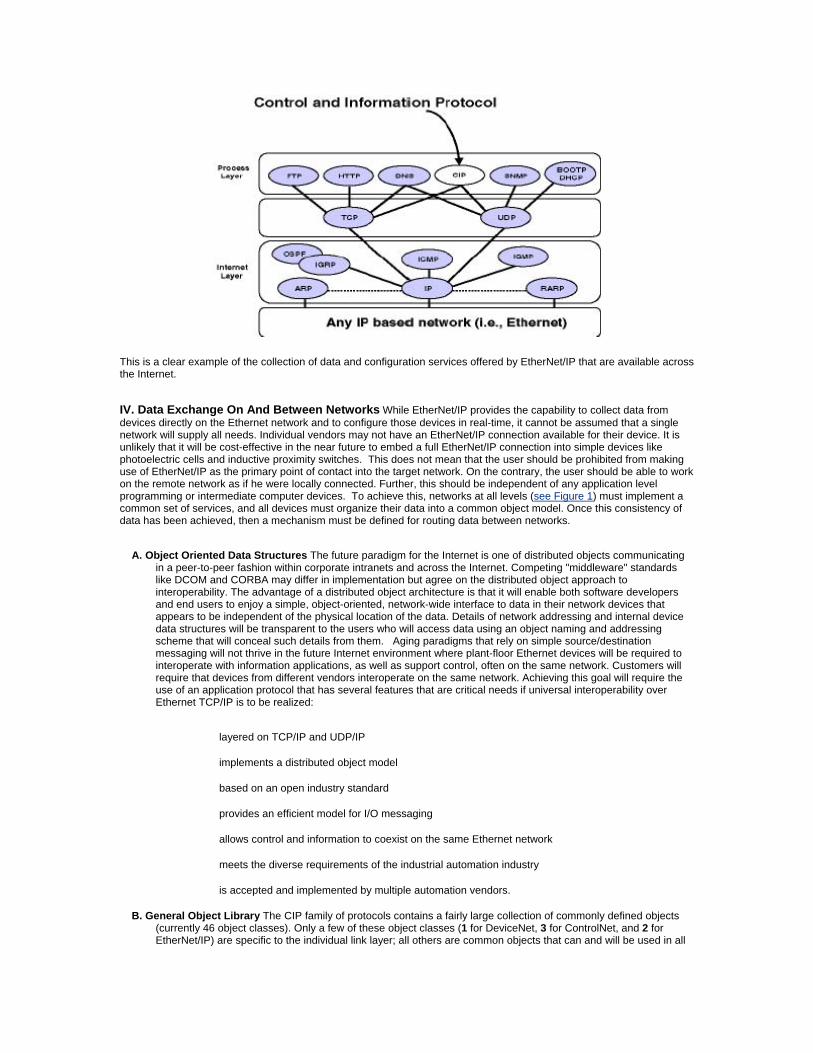
This is a clear example of the collection of data and configuration services offered by EtherNet/IP that are available across the Internet.
IV. Data Exchange On And Between Networks While EtherNet/IP provides the capability to collect data from devices directly on the Ethernet network and to configure those devices in real-time, it cannot be assumed that a single network will supply all needs. Individual vendors may not have an EtherNet/IP connection available for their device. It is unlikely that it will be cost-effective in the near future to embed a full EtherNet/IP connection into simple devices like photoelectric cells and inductive proximity switches. This does not mean that the user should be prohibited from making use of EtherNet/IP as the primary point of contact into the target network. On the contrary, the user should be able to work on the remote network as if he were locally connected. Further, this should be independent of any application level programming or intermediate computer devices. To achieve this, networks at all levels (see Figure 1) must implement a common set of services, and all devices must organize their data into a common object model. Once this consistency of data has been achieved, then a mechanism must be defined for routing data between networks.
A. Object Oriented Data Structures The future paradigm for the Internet is one of distributed objects communicating in a peer-to-peer fashion within corporate intranets and across the Internet. Competing "middleware" standards like DCOM and CORBA may differ in implementation but agree on the distributed object approach to interoperability. The advantage of a distributed object architecture is that it will enable both software developers and end users to enjoy a simple, object-oriented, network-wide interface to data in their network devices that appears to be independent of the physical location of the data. Details of network addressing and internal device data structures will be transparent to the users who will access data using an object naming and addressing scheme that will conceal such details from them. Aging paradigms that rely on simple source/destination messaging will not thrive in the future Internet environment where plant-floor Ethernet devices will be required to interoperate with information applications, as well as support control, often on the same network. Customers will require that devices from different vendors interoperate on the same network. Achieving this goal will require the use of an application protocol that has several features that are critical needs if universal interoperability over Ethernet TCP/IP is to be realized:
layered on TCP/IP and UDP/IP
implements a distributed object model
based on an open industry standard
provides an efficient model for I/O messaging
allows control and information to coexist on the same Ethernet network
meets the diverse requirements of the industrial automation industry
is accepted and implemented by multiple automation vendors.
B. General Object Library The CIP family of protocols contains a fairly large collection of commonly defined objects (currently 46 object classes). Only a few of these object classes (1 for DeviceNet, 3 for ControlNet, and 2 for EtherNet/IP) are specific to the individual link layer; all others are common objects that can and will be used in all
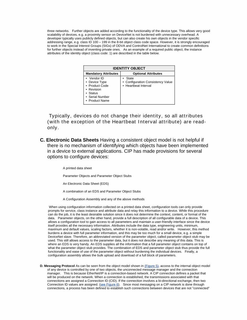
three networks. Further objects are added according to the functionality of the device type. This allows very good scalability of devices, e.g. a proximity sensor on DeviceNet is not burdened with unnecessary overhead. A developer typically uses publicly defined objects, but can also create his own objects in the vendor specific addressing range, e.g. class ID 100 – 199 in the 8-bit object class code space. However, it is strongly encouraged to work in the Special Interest Groups (SIGs) of ODVA and ControlNet International to create common definitions for further objects instead of inventing private ones. As an example of a required public object, the instance attributes of the identity object (class code: 1) are described in the table below.
IDENTITY OBJECT
Mandatory Attributes Optional Attributes • Vendor ID • Device Type • Product Code • Revision • Status • Serial Number • Product Name
• State • Configuration Consistency Value • Heartbeat Interval
Typically, devices do not change their identity, so all attributes (with the exception of the Heartbeat Interval attribute) are read-only.
C. Electronic Data Sheets Having a consistent object model is not helpful if there is no mechanism of identifying which objects have been implemented in a device to external applications. CIP has made provisions for several options to configure devices:
A printed data sheet
Parameter Objects and Parameter Object Stubs
An Electronic Data Sheet (EDS)
A combination of an EDS and Parameter Object Stubs
A Configuration Assembly and any of the above methods
When using configuration information collected on a printed data sheet, configuration tools can only provide prompts for service, class instance and attribute data and relay this information to a device. While this procedure can do the job, it is the least desirable solution since it does not determine the context, content, or format of the data. Parameter objects, on the other hand, provide a full description of all configurable data of a device. This allows a configuration tool to gain access to all parameters and maintain a user-friendly interface since the device itself provides all the necessary information. Attributes include the data type, engineering units, minimum, maximum and default values, scaling factors, whether it is non-volatile, read and/or write. However, this method burdens a device with full parameter information, and this may be too much for a small device, e.g. a simple DeviceNet slave. Therefore, an abbreviated version of the parameter object, called parameter object stub may be used. This still allows access to the parameter data, but it does not describe any meaning of this data. This is where an EDS is very handy. An EDS supplies all the information that a full parameter object contains on top of what the parameter object stub provides. The combination of EDS and parameter object stub thus provide the full functionality and ease of use of the parameter object without burdening the individual devices. Finally, a configuration assembly allows the bulk upload and download of a full block of parameters.
D. Messaging Protocol As can be seen from the object model shown in (Figure 5), access to the internal object model of any device is controlled by one of two objects, the unconnected message manager and the connection manager. This is because EtherNet/IP is a connection-based network. A CIP connection defines a packet that will be produced on the network. When a connection is established, the transmissions associated with that connections are assigned a Connection ID (CID). If the connection involves a bi-directional exchange, then two Connection ID values are assigned. (see Figure 6). Since most messaging on a CIP network is done through connections, a process has been defined to establish such connections between devices that are not "connected"
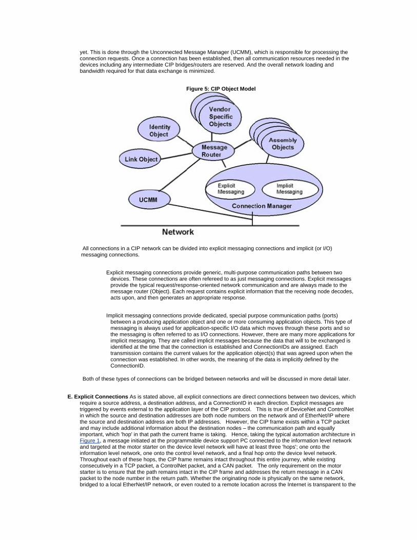
yet. This is done through the Unconnected Message Manager (UCMM), which is responsible for processing the connection requests. Once a connection has been established, then all communication resources needed in the devices including any intermediate CIP bridges/routers are reserved. And the overall network loading and bandwidth required for that data exchange is minimized.
Figure 5: CIP Object Model
All connections in a CIP network can be divided into explicit messaging connections and implicit (or I/O) messaging connections.
Explicit messaging connections provide generic, multi-purpose communication paths between two devices. These connections are often refereed to as just messaging connections. Explicit messages provide the typical request/response-oriented network communication and are always made to the message router (Object). Each request contains explicit information that the receiving node decodes, acts upon, and then generates an appropriate response.
Implicit messaging connections provide dedicated, special purpose communication paths (ports) between a producing application object and one or more consuming application objects. This type of messaging is always used for application-specific I/O data which moves through these ports and so the messaging is often referred to as I/O connections. However, there are many more applications for implicit messaging. They are called implicit messages because the data that will to be exchanged is identified at the time that the connection is established and ConnectionIDs are assigned. Each transmission contains the current values for the application object(s) that was agreed upon when the connection was established. In other words, the meaning of the data is implicitly defined by the ConnectionID.
Both of these types of connections can be bridged between networks and will be discussed in more detail later.
E. Explicit Connections As is stated above, all explicit connections are direct connections between two devices, which require a source address, a destination address, and a ConnectionID in each direction. Explicit messages are triggered by events external to the application layer of the CIP protocol. This is true of DeviceNet and ControlNet in which the source and destination addresses are both node numbers on the network and of EtherNet/IP where the source and destination address are both IP addresses. However, the CIP frame exists within a TCP packet and may include additional information about the destination nodes – the communication path and equally important, which 'hop' in that path the current frame is taking. Hence, taking the typical automation architecture in Figure 1, a message initiated at the programmable device support PC connected to the information level network and targeted at the motor starter on the device level network will have at least three 'hops'; one onto the information level network, one onto the control level network, and a final hop onto the device level network. Throughout each of these hops, the CIP frame remains intact throughout this entire journey, while existing consecutively in a TCP packet, a ControlNet packet, and a CAN packet. The only requirement on the motor starter is to ensure that the path remains intact in the CIP frame and addresses the return message in a CAN packet to the node number in the return path. Whether the originating node is physically on the same network, bridged to a local EtherNet/IP network, or even routed to a remote location across the Internet is transparent to the
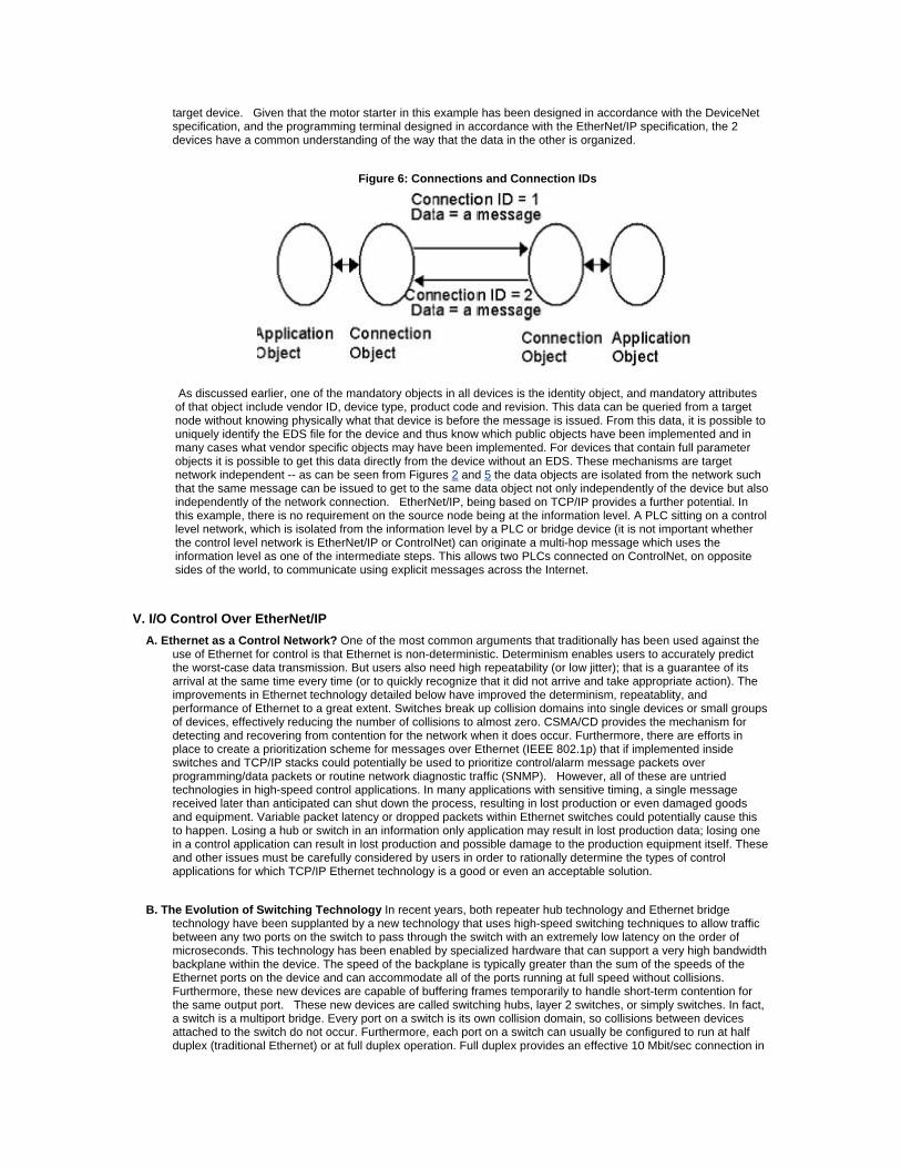
target device. Given that the motor starter in this example has been designed in accordance with the DeviceNet specification, and the programming terminal designed in accordance with the EtherNet/IP specification, the 2 devices have a common understanding of the way that the data in the other is organized.
Figure 6: Connections and Connection IDs
As discussed earlier, one of the mandatory objects in all devices is the identity object, and mandatory attributes of that object include vendor ID, device type, product code and revision. This data can be queried from a target node without knowing physically what that device is before the message is issued. From this data, it is possible to uniquely identify the EDS file for the device and thus know which public objects have been implemented and in many cases what vendor specific objects may have been implemented. For devices that contain full parameter objects it is possible to get this data directly from the device without an EDS. These mechanisms are target network independent -- as can be seen from Figures 2 and 5 the data objects are isolated from the network such that the same message can be issued to get to the same data object not only independently of the device but also independently of the network connection. EtherNet/IP, being based on TCP/IP provides a further potential. In this example, there is no requirement on the source node being at the information level. A PLC sitting on a control level network, which is isolated from the information level by a PLC or bridge device (it is not important whether the control level network is EtherNet/IP or ControlNet) can originate a multi-hop message which uses the information level as one of the intermediate steps. This allows two PLCs connected on ControlNet, on opposite sides of the world, to communicate using explicit messages across the Internet.
V. I/O Control Over EtherNet/IP
A. Ethernet as a Control Network? One of the most common arguments that traditionally has been used against the use of Ethernet for control is that Ethernet is non-deterministic. Determinism enables users to accurately predict the worst-case data transmission. But users also need high repeatability (or low jitter); that is a guarantee of its arrival at the same time every time (or to quickly recognize that it did not arrive and take appropriate action). The improvements in Ethernet technology detailed below have improved the determinism, repeatablity, and performance of Ethernet to a great extent. Switches break up collision domains into single devices or small groups of devices, effectively reducing the number of collisions to almost zero. CSMA/CD provides the mechanism for detecting and recovering from contention for the network when it does occur. Furthermore, there are efforts in place to create a prioritization scheme for messages over Ethernet (IEEE 802.1p) that if implemented inside switches and TCP/IP stacks could potentially be used to prioritize control/alarm message packets over programming/data packets or routine network diagnostic traffic (SNMP). However, all of these are untried technologies in high-speed control applications. In many applications with sensitive timing, a single message received later than anticipated can shut down the process, resulting in lost production or even damaged goods and equipment. Variable packet latency or dropped packets within Ethernet switches could potentially cause this to happen. Losing a hub or switch in an information only application may result in lost production data; losing one in a control application can result in lost production and possible damage to the production equipment itself. These and other issues must be carefully considered by users in order to rationally determine the types of control applications for which TCP/IP Ethernet technology is a good or even an acceptable solution.
B. The Evolution of Switching Technology In recent years, both repeater hub technology and Ethernet bridge technology have been supplanted by a new technology that uses high-speed switching techniques to allow traffic between any two ports on the switch to pass through the switch with an extremely low latency on the order of microseconds. This technology has been enabled by specialized hardware that can support a very high bandwidth backplane within the device. The speed of the backplane is typically greater than the sum of the speeds of the Ethernet ports on the device and can accommodate all of the ports running at full speed without collisions. Furthermore, these new devices are capable of buffering frames temporarily to handle short-term contention for the same output port. These new devices are called switching hubs, layer 2 switches, or simply switches. In fact, a switch is a multiport bridge. Every port on a switch is its own collision domain, so collisions between devices attached to the switch do not occur. Furthermore, each port on a switch can usually be configured to run at half duplex (traditional Ethernet) or at full duplex operation. Full duplex provides an effective 10 Mbit/sec connection in
each direction (20 Mbit/sec total) between an attached device and the switch. For fast Ethernet, the full duplex speed is 100 Mbit/sec in each direction (200 Mbit/sec total). Like traditional bridges, switches build and maintain internal tables that map Ethernet addresses to ports. A packet received on one port is rapidly "switched" to the appropriate output port, typically within microseconds. Advanced switches support a virtual LAN (VLAN) feature that allows users to configure the switch so that ports are subdivided into groups such that all packets received on one port of a group will only be transmitted to another port within the group. The receiving port and the group of transmitting ports constitute a VLAN. VLANs may typically be overlapped within a switch, such that any one port may appear on multiple VLANs. This feature allows the user a great deal of flexibility over partitioning the ports on a switch into multiple overlapping collision domains. Switches are capable of handling a greater throughput than repeater hubs without experiencing the collision-induced delays that can be experienced by devices on a repeater hub as network traffic increases. This makes them a good choice for replacing repeater hubs on loaded networks that are experiencing an unacceptable level of collision-induced delays. Although switches are currently more expensive than repeater hubs, their cost is dropping and will soon be low enough that switches will likely replace repeater hubs as the network concentrator of choice for all Ethernet networks, not just those used for control. It is important to note that switches do have some performance limitations that may affect some applications. If a switch experiences internal congestion due to message packets on multiple input ports contending for transmission on the same output port, the switch may simply drop packets. Or it may force a collision back to the transmitting devices, so they back off long enough for the congestion to clear. The approach that is taken depends upon the implementation chosen by the switch vendor. In either case, a variable latency is inserted into the message stream, which is generally not a problem for office applications but may have profound impact on industrial automation applications. Although switches isolate separate collision domains on each port, they do not create separate broadcast domains. However, each VLAN is a separate broadcast domain, if this feature is enabled on the switch. An Ethernet broadcast message that is received on any port will be re-transmitted on all switch ports to all attached devices. This means that switches do not eliminate the problem of excessive broadcast traffic that can cause severe performance degradation across an entire Ethernet network when a damaged or improperly configured device is attached to the network. Some switch vendors are working on proprietary methods for suppressing excessive broadcast messages in their switches, but this is not universal. Broadcast messages are common on Ethernet networks that carry the TCP/IP protocol because Ethernet broadcast messages are used by TCP/IP for address resolution. However, broadcast traffic represents a small percentage of network traffic on a network that is properly configured and operating normally. Also, switches and repeater hubs are active devices, containing complex digital circuitry and requiring power (AC in most cases) to operate. The failure of a switch or hub will effectively cause a communication failure for all of the devices attached to that device's ports, including other hubs or switches that may be attached to one or more ports of the failed device. The devices attached to the failed hub or switch will be unable to communicate with the rest of the plant network until the switch is replaced or repaired. Furthermore, most Ethernet media components have been designed for use in an office or light industrial environment. They have not been designed and tested for compliance to the rigorous environmental standards typical of industrial control devices (i.e., extended temperature range, industrial CE mark, shock and vibration, etc.). This may become an issue as the mission for Ethernet on the plant floor is expanded into new areas.
C. The Evolution of Ethernet Performance More recent developments in Ethernet technology include Fast Ethernet and Gigabit Ethernet. Fast Ethernet is defined and documented in IEEE specification 802.3u. Fast Ethernet is basically Ethernet running at 100 Mbits/sec. Fast Ethernet and 10 Mbit Ethernet use the same frame structure, addressing scheme, and CSMA/CD access method. However, all network timing parameters must be scaled by a factor of 10 when configuring a Fast Ethernet network. This tends to reduce the distances between nodes in some configurations when compared to a 10 Mbit network. Fast Ethernet provides a wire speed that is 10 times as fast as traditional Ethernet, which tends to benefit bandwidth hungry applications, such as video and audio transmission, as well as the transfer of large data files over the network. However, most applications will not enjoy a substantial performance increase due to increased wire speed alone. In particular, a plant-floor network of small microprocessor-based intelligent I/O blocks, sensors, actuators, drives and other device interfaces are likely to consume and produce small amounts of data encapsulated in 64 byte Ethernet frames (the smallest frame size supported by Ethernet). The performance of these devices is more likely to be limited by the speed of their microprocessor and embedded firmware than the wire speed. It is unlikely a network of such devices would fully utilize the full 10 Mbit/sec Ethernet bandwidth, unless an inefficient application layer protocol was utilized that repeatedly polled the devices in point-to-point fashion. One area of performance wherein 100 Mbit Ethernet may show noticeable improvement over 10 Mbit Ethernet is in the area of collision recovery. As mentioned earlier, the backoff times for 100 Mbit Ethernet are one tenth of those for 10 Mbit Ethernet. On a loaded network where collisions are an issue, 100 Mbit Ethernet may show noticeably better performance than 10 Mbit Ethernet. Additionally, it would be expected that a 100 Mbit Ethernet network would be able to handle a larger offered load than a 10 Mbit Ethernet network before collisions became an issue. If the application requires the use of multiple switches, the links between the switches may benefit from the higher speed. However, if loading and collisions are not already an issue on a 10 Mbit Ethernet network, simply upgrading to 100 Mbit Ethernet may not show sufficient improvement to justify the investment.
D. Implicit (I/O) Messaging over EtherNet/IP In section 4.5, we discussed the communication path and the use of explicit messages and unconnected messages to exchange point-to-point messages between nodes. The second type of messaging, implicit messaging is used where the exchange of data between nodes is transparent to the user and takes place within the application layer of the protocol, with both producing and consuming nodes aware of the content of the message before transmission. While commonly used for I/O messages, these make
full use of the producer/consumer model and are commonly used for scheduled communication between controllers as well. There are four principal types of implicit message available within the CIP specification:
Polled
Change of State
Cyclic
Strobed
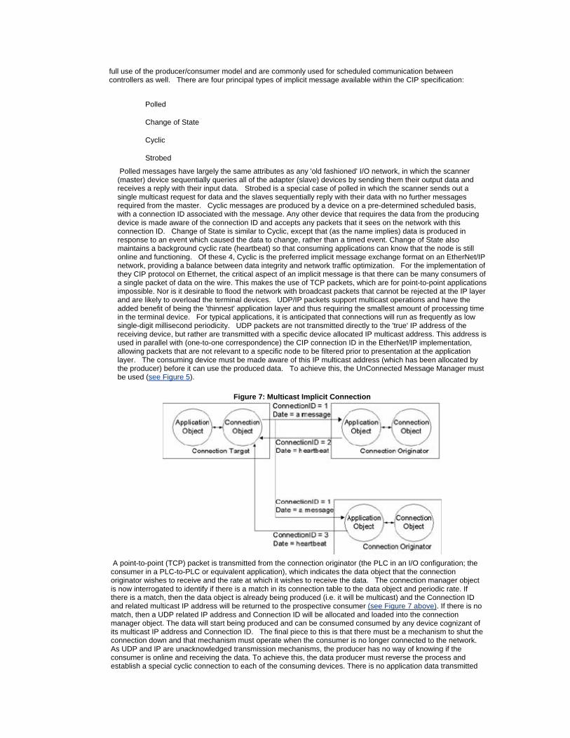
Polled messages have largely the same attributes as any 'old fashioned' I/O network, in which the scanner (master) device sequentially queries all of the adapter (slave) devices by sending them their output data and receives a reply with their input data. Strobed is a special case of polled in which the scanner sends out a single multicast request for data and the slaves sequentially reply with their data with no further messages required from the master. Cyclic messages are produced by a device on a pre-determined scheduled basis, with a connection ID associated with the message. Any other device that requires the data from the producing device is made aware of the connection ID and accepts any packets that it sees on the network with this connection ID. Change of State is similar to Cyclic, except that (as the name implies) data is produced in response to an event which caused the data to change, rather than a timed event. Change of State also maintains a background cyclic rate (heartbeat) so that consuming applications can know that the node is still online and functioning. Of these 4, Cyclic is the preferred implicit message exchange format on an EtherNet/IP network, providing a balance between data integrity and network traffic optimization. For the implementation of they CIP protocol on Ethernet, the critical aspect of an implicit message is that there can be many consumers of a single packet of data on the wire. This makes the use of TCP packets, which are for point-to-point applications impossible. Nor is it desirable to flood the network with broadcast packets that cannot be rejected at the IP layer and are likely to overload the terminal devices. UDP/IP packets support multicast operations and have the added benefit of being the 'thinnest' application layer and thus requiring the smallest amount of processing time in the terminal device. For typical applications, it is anticipated that connections will run as frequently as low single-digit millisecond periodicity. UDP packets are not transmitted directly to the 'true' IP address of the receiving device, but rather are transmitted with a specific device allocated IP multicast address. This address is used in parallel with (one-to-one correspondence) the CIP connection ID in the EtherNet/IP implementation, allowing packets that are not relevant to a specific node to be filtered prior to presentation at the application layer. The consuming device must be made aware of this IP multicast address (which has been allocated by the producer) before it can use the produced data. To achieve this, the UnConnected Message Manager must be used (see Figure 5).
Figure 7: Multicast Implicit Connection
A point-to-point (TCP) packet is transmitted from the connection originator (the PLC in an I/O configuration; the consumer in a PLC-to-PLC or equivalent application), which indicates the data object that the connection originator wishes to receive and the rate at which it wishes to receive the data. The connection manager object is now interrogated to identify if there is a match in its connection table to the data object and periodic rate. If there is a match, then the data object is already being produced (i.e. it will be multicast) and the Connection ID and related multicast IP address will be returned to the prospective consumer (see Figure 7 above). If there is no match, then a UDP related IP address and Connection ID will be allocated and loaded into the connection manager object. The data will start being produced and can be consumed consumed by any device cognizant of its multicast IP address and Connection ID. The final piece to this is that there must be a mechanism to shut the connection down and that mechanism must operate when the consumer is no longer connected to the network. As UDP and IP are unacknowledged transmission mechanisms, the producer has no way of knowing if the consumer is online and receiving the data. To achieve this, the data producer must reverse the process and establish a special cyclic connection to each of the consuming devices. There is no application data transmitted
through this connection, which is called a 'heartbeat.' If the producing node times out all of the heartbeat connections that are associated with a specific produced data object, then all connections associated with that data object are closed. Consequently, by use of TCP packets to establish the connection between devices and then UDP connections to pipe the I/O data objects, network bandwidth utilization is minimized. With the advent of 100MBps Ethernet, this is not as critical as it once was. More significantly, the number of packets that each terminal node has to process is minimized, and, thus, its ability to handle implicit connections is maximized.
VI. Conformance Testing As interoperability is one of the principal goals of both ODVA and ControlNet International in generating the EtherNet/IP specification, those organizations have put a number of independent conformance test facilities in place, with one based in Europe, one in North America, and one in Japan. A joint special interest group (JSIG) has been set up between ODVA and ControlNet International to ensure that consistent test procedures are run across these labs. By providing these independent facilities, it will be practical for competitive vendors to offer products with no fear of loss of intellectual property but with the confidence that the products will integrate seamlessly. This will, in turn, ensure that users are able to make decisions based on the merits of individual components and suppliers rather than feel tied to a single vendor. The first of these labs, at the University of Michigan, USA was opened August 10, 2001. This is to be followed by similar units at the University of Warwick, UK and the Advanced Software Technology and Mechatronics Research Institute (ASTEM RI) in Kyoto, Japan.
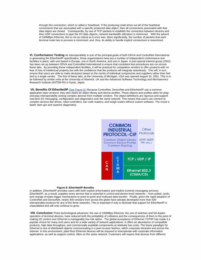
VII. Benefits Of EtherNet/IP (See Figure 8.) Because ControlNet, DeviceNet and EtherNet/IP use a common application layer protocol, they also share an object library and device profiles. These objects and profiles allow for plug-and-play interoperability among complex devices from multiple vendors. The object definitions are rigorous and support real-time I/O messaging, configuration and diagnostics over the same network. This means that users can connect to complex devices like drives, robot controllers, bar code readers, and weigh scales without custom software. The result is faster start ups and superior diagnostics.
Figure 8: EtherNet/IP Benefits In addition, EtherNet/IP provides users with both explicit (information) and implicit (control) messaging services. EtherNet/IP, as a result, supplies every service that is essential in control and device-level networks – from polled, cyclic, and change-of-state trigger mechanisms to point-to-point and multicast data transfer. Finally, given the rapid adoption of ControlNet and DeviceNet, nearly 400 vendors from across the globe have already developed more than 500 interoperable products for any of the three networks. This is important if only to illustrate that support for EtherNet/IP is unparalleled and will only continue to grow.
VIII. Conclusion Three technological advances: the use of 100MBps Ethernet, the use of switches and full duplex operation of terminal devices, have reduced both the probability of collisions and the consequences of them to the point of making I/O control over Ethernet a manageably low risk option. The global acceptance of Ethernet TCP/IP has made it a popular choice for many end users and for a wide variety of network applications. It offers an abundance of compatible products, high data throughput, and commercially available components at relatively low costs. The future paradigm for Ethernet is one of distributed objects communicating in a peer-to-peer fashion, within corporate intranets and across the Internet. In this environment, plant-floor Ethernet devices will be required to interoperate with corporate information applications, as well as support control, often on the same network. Customers will require that devices from different
vendors interoperate on the same network. Achieving this goal will require the adoption of an Application Layer that:
is layered on TCP/IP (and UDP/IP) implements a distributed object model
allows control and information to coexist on the same Ethernet network
provides producer/consumer network services
meets the diverse requirements of the industrial automation industry
is accepted and implemented by multiple automation vendors
This is a critical need in the industry if real-time control and universal interoperability over Ethernet TCP/UDP/IP is to be realized.
IX. References [1] DeviceNet Specification, Release 2.0, including Errata 4, April 1, 2001, © 1995-2001 by Open DeviceNet Vendor Association. [2] ControlNet Specification, Release 2.0, including Errata 2, December 31, 1999, © 1998, 1999 by ControlNet International. [3] EtherNet/IP Specification, Release 1.0, June 5, 2001, © 2000, 2001 by ControlNet International and Open DeviceNet Vendor association.
© Institute of Electrical and Electronic Engineers, EFTA 2001
Publication ENET-WP001A-EN-P — October, 2001 Copyright © 2001 Rockwell Automation, Inc. All rights reserved. Printed in USA Supersedes Publication 000-0000-0000 — Month, Year
Recommended