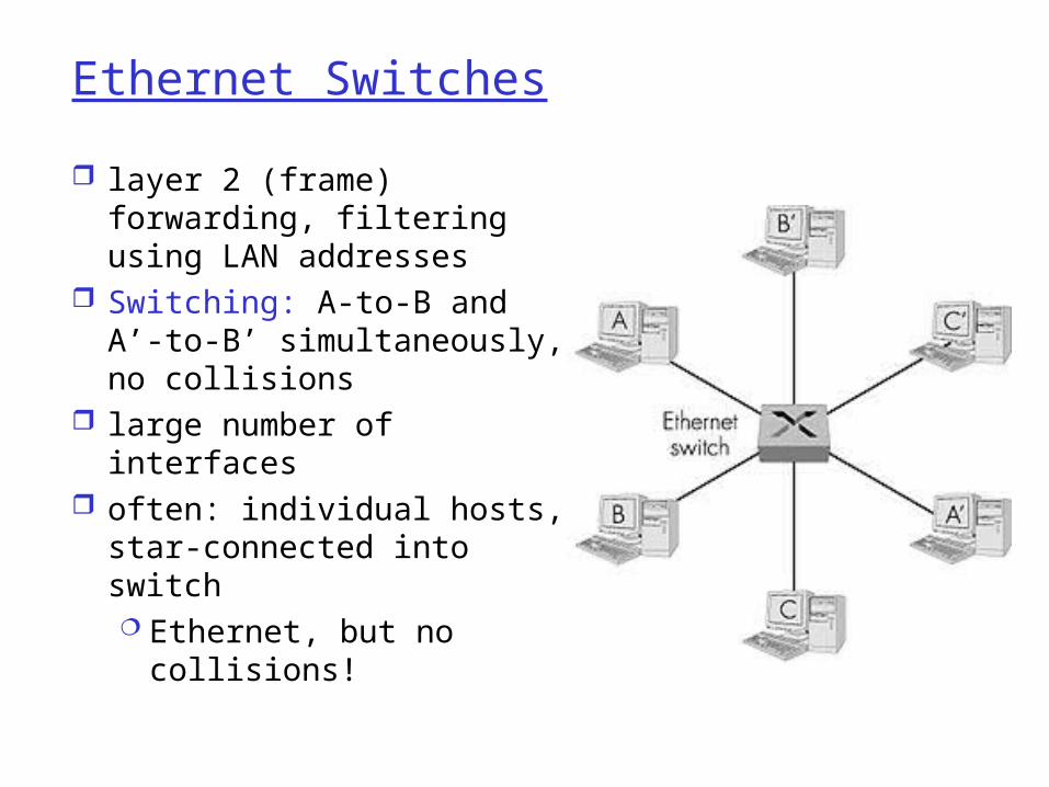
Ethernet Switches
layer 2 (frame) forwarding, filtering using LAN addresses
Switching: A-to-B and A’-to-B’ simultaneously, no collisions
large number of interfaces often: individual hosts,
star-connected into switch Ethernet, but no
collisions!

Ethernet Switches
cut-through switching: frame forwarded from input to output port without awaiting for assembly of entire frame slight reduction in latency
combinations of shared/dedicated, 10/100/1000 Mbps interfaces

Ethernet Switches (more)
Dedicated
Shared

IEEE 802.11 Wireless LAN
wireless LANs: untethered (often mobile) networking
IEEE 802.11 standard: MAC protocol unlicensed frequency spectrum: 900Mhz, 2.4Ghz
Basic Service Set (BSS) (a.k.a. “cell”) contains: wireless hosts access point (AP):
base station BSS’s combined to form
distribution system (DS)

Ad Hoc Networks
Ad hoc network: IEEE 802.11 stations can dynamically form network without AP
Applications: “laptop” meeting in conference room, car interconnection of “personal” devices battlefield
IETF MANET (Mobile Ad hoc Networks) working group

IEEE 802.11 MAC Protocol: CSMA/CA
802.11 CSMA: sender- if sense channel idle for
DISF sec. then transmit entire frame
(no collision detection)-if sense channel busy
then binary backoff
802.11 CSMA receiver:if received OK return ACK after SIFS
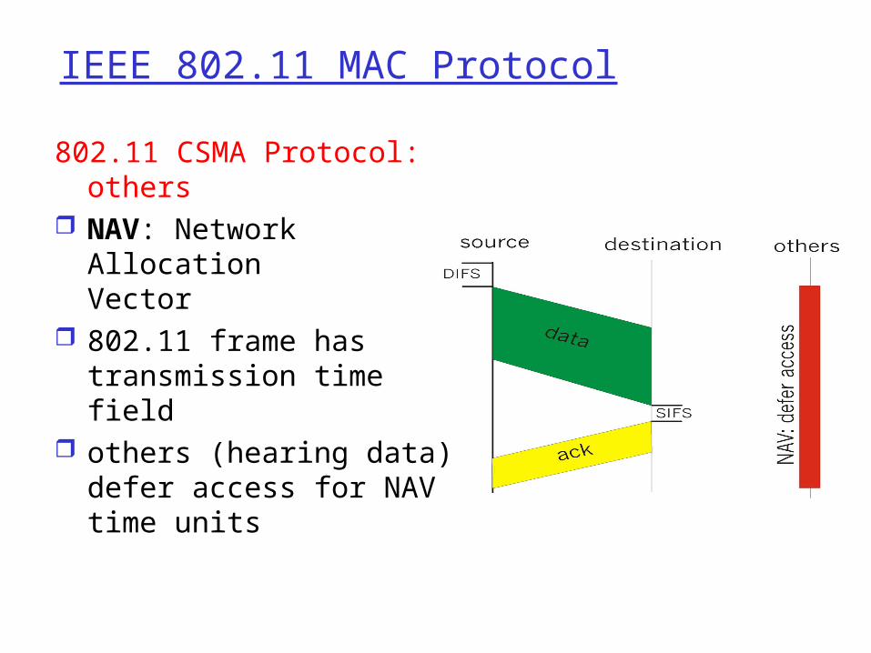
IEEE 802.11 MAC Protocol
802.11 CSMA Protocol: others
NAV: Network Allocation Vector
802.11 frame has transmission time field
others (hearing data) defer access for NAV time units

Hidden Terminal effect
hidden terminals: A, C cannot hear each other obstacles, signal attenuation collisions at B
goal: avoid collisions at B CSMA/CA: CSMA with Collision Avoidance

Collision Avoidance: RTS-CTS exchange
CSMA/CA: explicit channel reservation sender: send short
RTS: request to send receiver: reply with
short CTS: clear to send
CTS reserves channel for sender, notifying (possibly hidden) stations
avoid hidden station collisions

Collision Avoidance: RTS-CTS exchange
RTS and CTS short: collisions less likely, of
shorter duration end result similar to
collision detection IEEE 802.11 alows:
CSMA CSMA/CA: reservations polling from AP

Point to Point Data Link Control
one sender, one receiver, one link: easier than broadcast link: no Media Access Control no need for explicit MAC addressing e.g., dialup link, ISDN line
popular point-to-point DLC protocols: PPP (point-to-point protocol) HDLC: High level data link control (Data link
used to be considered “high layer” in protocol stack!

PPP Design Requirements [RFC 1557] packet framing: encapsulation of network-
layer datagram in data link frame carry network layer data of any network
layer protocol (not just IP) at same time ability to demultiplex upwards
bit transparency: must carry any bit pattern in the data field
error detection (no correction) connection liveness: detect, signal link failure
to network layer network layer address negotiation: endpoint
can learn/configure each other’s network address
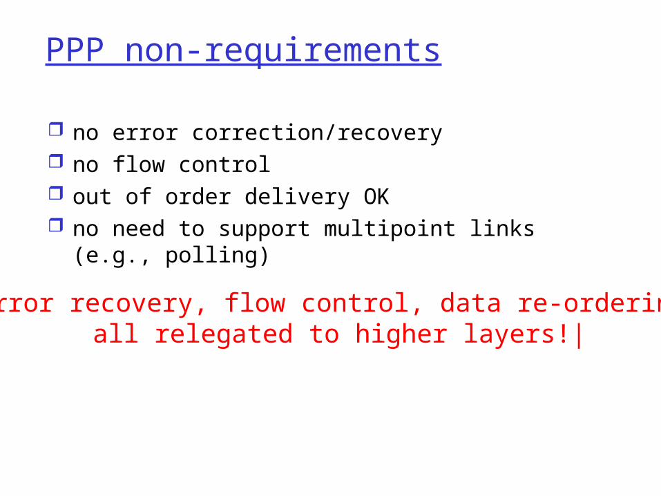
PPP non-requirements
no error correction/recovery no flow control out of order delivery OK no need to support multipoint links (e.g.,
polling)
Error recovery, flow control, data re-ordering all relegated to higher layers!|
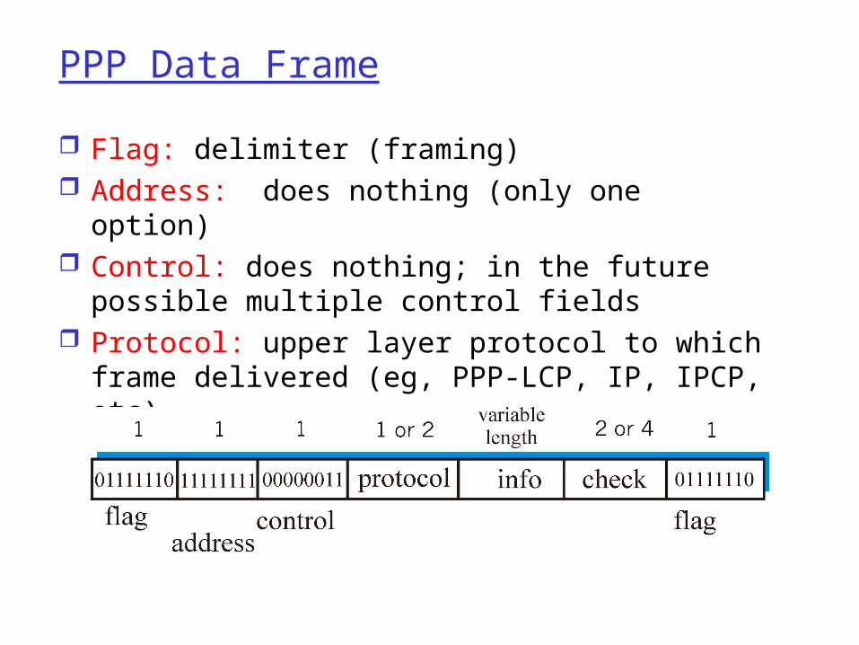
PPP Data Frame
Flag: delimiter (framing) Address: does nothing (only one option) Control: does nothing; in the future possible
multiple control fields Protocol: upper layer protocol to which frame
delivered (eg, PPP-LCP, IP, IPCP, etc)
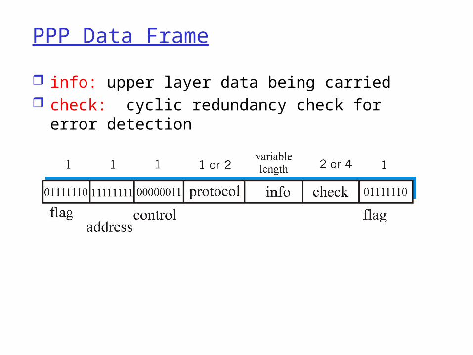
PPP Data Frame
info: upper layer data being carried check: cyclic redundancy check for error
detection
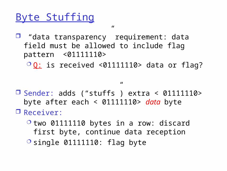
Byte Stuffing
“data transparency” requirement: data field must be allowed to include flag pattern <01111110> Q: is received <01111110> data or flag?
Sender: adds (“stuffs”) extra < 01111110> byte after each < 01111110> data byte
Receiver: two 01111110 bytes in a row: discard first
byte, continue data reception single 01111110: flag byte

Byte Stuffing
flag bytepatternin datato send
flag byte pattern plusstuffed byte in transmitted data
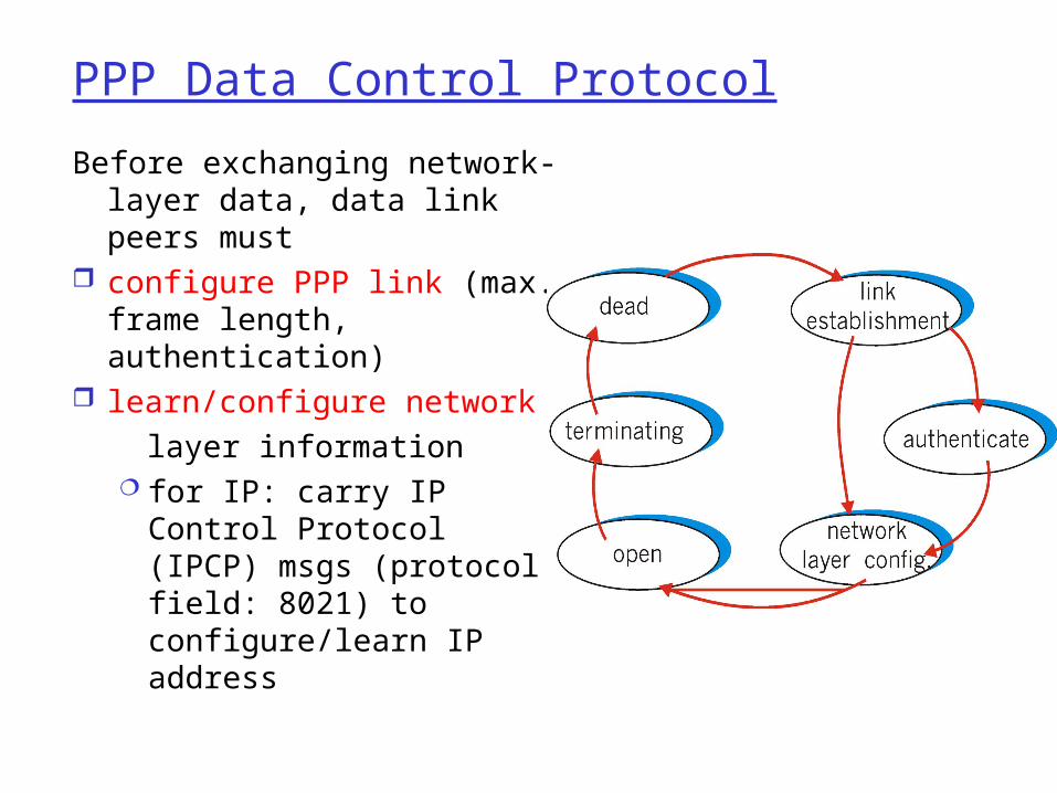
PPP Data Control Protocol
Before exchanging network-layer data, data link peers must
configure PPP link (max. frame length, authentication)
learn/configure network layer information
for IP: carry IP Control Protocol (IPCP) msgs (protocol field: 8021) to configure/learn IP address

Asynchronous Transfer Mode: ATM
1980s/1990’s standard for high-speed (155Mbps to 622 Mbps and higher) Broadband Integrated Service Digital Network architecture
Goal: integrated, end-end transport of carry voice, video, data meeting timing/QoS requirements of voice,
video (versus Internet best-effort model) “next generation” telephony: technical roots
in telephone world packet-switching (fixed length packets, called
“cells”) using virtual circuits

ATM architecture
adaptation layer: only at edge of ATM network data segmentation/reassembly roughly analagous to Internet transport layer
ATM layer: “network” layer cell switching, routing
physical layer

ATM: network or link layer?
Vision: end-to-end transport: “ATM from desktop to desktop” ATM is a network
technology
Reality: used to connect IP backbone routers “IP over ATM” ATM as switched
link layer, connecting IP routers

ATM Adaptation Layer (AAL)
ATM Adaptation Layer (AAL): “adapts” upper layers (IP or native ATM applications) to ATM layer below
AAL present only in end systems, not in switches
AAL layer segment (header/trailer fields, data) fragmented across multiple ATM cells analogy: TCP segment in many IP packets

ATM Adaption Layer (AAL) [more]
Different versions of AAL layers, depending on ATM service class:
AAL1: for CBR (Constant Bit Rate) services, e.g. circuit emulation
AAL2: for VBR (Variable Bit Rate) services, e.g., MPEG video AAL5: for data (eg, IP datagrams)
AAL PDU
ATM cell
User data

AAL5 - Simple And Efficient AL (SEAL) AAL5: low overhead AAL used to carry IP
datagrams 4 byte cyclic redundancy check PAD ensures payload multiple of 48bytes large AAL5 data unit to be fragmented into 48-byte
ATM cells
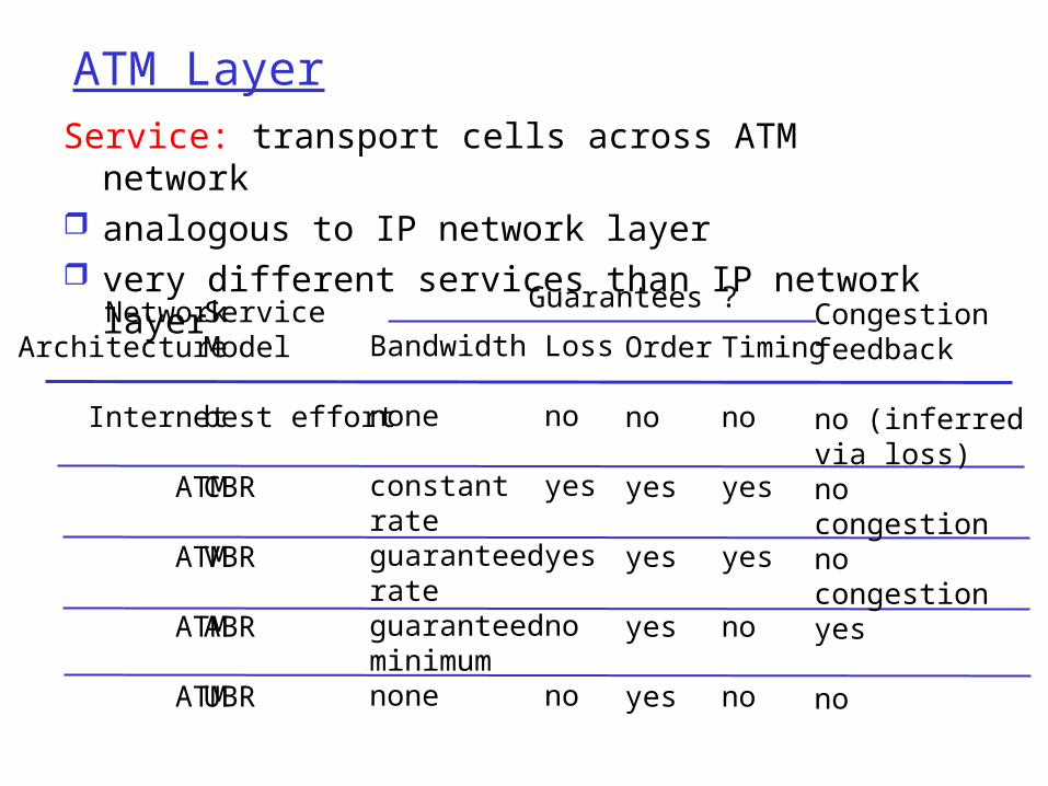
ATM LayerService: transport cells across ATM network analogous to IP network layer very different services than IP network layer
NetworkArchitecture
Internet
ATM
ATM
ATM
ATM
ServiceModel
best effort
CBR
VBR
ABR
UBR
Bandwidth
none
constantrateguaranteedrateguaranteed minimumnone
Loss
no
yes
yes
no
no
Order
no
yes
yes
yes
yes
Timing
no
yes
yes
no
no
Congestionfeedback
no (inferredvia loss)nocongestionnocongestionyes
no
Guarantees ?
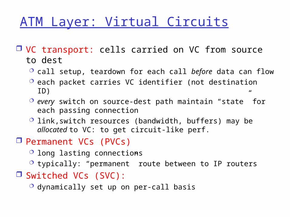
ATM Layer: Virtual Circuits
VC transport: cells carried on VC from source to dest call setup, teardown for each call before data can flow each packet carries VC identifier (not destination ID) every switch on source-dest path maintain “state” for
each passing connection link,switch resources (bandwidth, buffers) may be
allocated to VC: to get circuit-like perf.
Permanent VCs (PVCs) long lasting connections typically: “permanent” route between to IP routers
Switched VCs (SVC): dynamically set up on per-call basis

ATM VCs
Advantages of ATM VC approach: QoS performance guarantee for connection
mapped to VC (bandwidth, delay, delay jitter)
Drawbacks of ATM VC approach: Inefficient support of datagram traffic one PVC between each source/dest pair)
does not scale (N*2 connections needed) SVC introduces call setup latency,
processing overhead for short lived connections
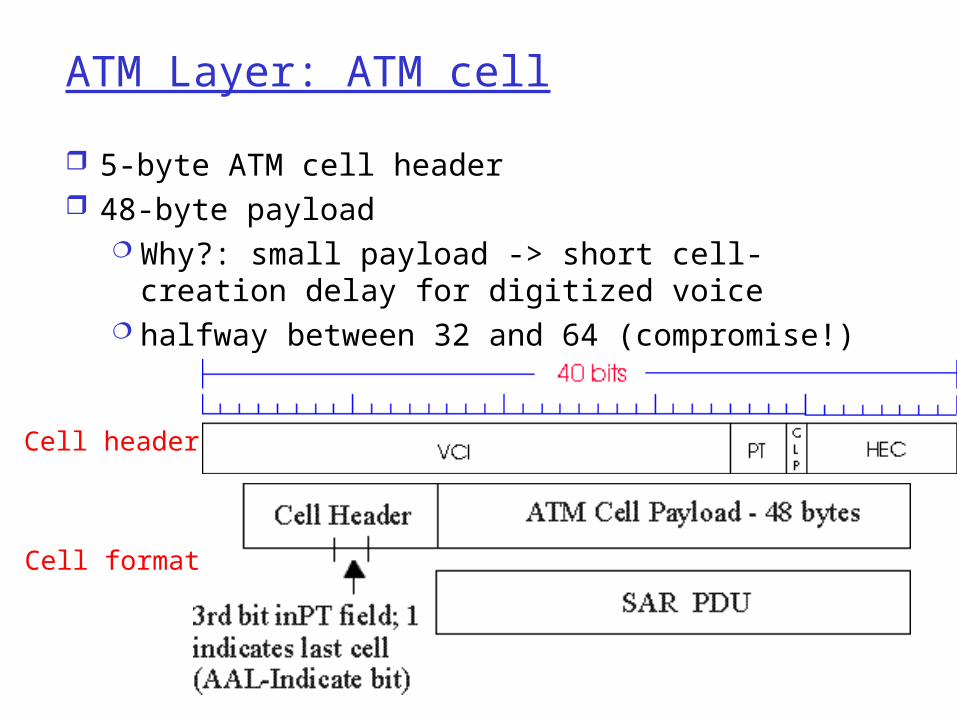
ATM Layer: ATM cell
5-byte ATM cell header 48-byte payload
Why?: small payload -> short cell-creation delay for digitized voice
halfway between 32 and 64 (compromise!)
Cell header
Cell format

ATM cell header
VCI: virtual channel ID will change from link to link thru net
PT: Payload type (e.g. RM cell versus data cell)
CLP: Cell Loss Priority bit CLP = 1 implies low priority cell, can be
discarded if congestion HEC: Header Error Checksum
cyclic redundancy check
ATM Physical Layer (more)
Two pieces (sublayers) of physical layer: Transmission Convergence Sublayer (TCS):
adapts ATM layer above to PMD sublayer below
Physical Medium Dependent: depends on physical medium being used
TCS Functions: Header checksum generation: 8 bits CRC Cell delineation With “unstructured” PMD sublayer, transmission of
idle cells when no data cells to send
ATM Physical Layer
Physical Medium Dependent (PMD) sublayer SONET/SDH: transmission frame structure (like a
container carrying bits); bit synchronization; bandwidth partitions (TDM); several speeds: OC1 = 51.84 Mbps; OC3 = 155.52
Mbps; OC12 = 622.08 Mbps TI/T3: transmission frame structure (old telephone
hierarchy): 1.5 Mbps/ 45 Mbps unstructured: just cells (busy/idle)

IP-Over-ATMClassic IP only 3 “networks” (e.g., LAN segments) MAC (802.3) and IP addresses
IP over ATM replace “network”
(e.g., LAN segment) with ATM network
ATM addresses, IP addresses
ATMnetwork
EthernetLANs
EthernetLANs
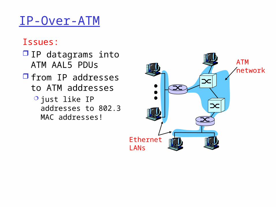
IP-Over-ATM
Issues: IP datagrams into
ATM AAL5 PDUs from IP addresses
to ATM addresses just like IP
addresses to 802.3 MAC addresses!
ATMnetwork
EthernetLANs

Datagram Journey in IP-over-ATM Network at Source Host:
IP layer finds mapping between IP, ATM dest address (using ARP)
passes datagram to AAL5 AAL5 encapsulates data, segments to cells, passes to
ATM layer ATM network: moves cell along VC to destination
at Destination Host: AAL5 reassembles cells into original datagram if CRC OK, datgram is passed to IP
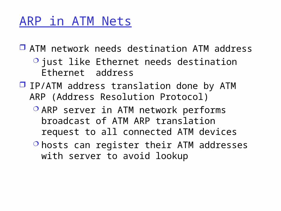
ARP in ATM Nets
ATM network needs destination ATM address just like Ethernet needs destination Ethernet
address IP/ATM address translation done by ATM ARP
(Address Resolution Protocol) ARP server in ATM network performs
broadcast of ATM ARP translation request to all connected ATM devices
hosts can register their ATM addresses with server to avoid lookup

X.25 and Frame Relay
Like ATM: wide area network technologies virtual circuit oriented origins in telephony world can be used to carry IP datagrams
can thus be viewed as Link Layers by IP protocol

X.25
X.25 builds VC between source and destination for each user connection
Per-hop control along path error control (with retransmissions) on each
hop using LAP-B• variant of the HDLC protocol
per-hop flow control using credits• congestion arising at intermediate node
propagates to previous node on path• back to source via back pressure

IP versus X.25
X.25: reliable in-sequence end-end delivery from end-to-end “intelligence in the network”
IP: unreliable, out-of-sequence end-end delivery “intelligence in the endpoints”
gigabit routers: limited processing possible
2000: IP wins

Frame Relay
Designed in late ‘80s, widely deployed in the ‘90s
Frame relay service: no error control end-to-end congestion control

Frame Relay (more)
Designed to interconnect corporate customer LANs typically permanent VC’s: “pipe” carrying
aggregate traffic between two routers
switched VC’s: as in ATM corporate customer leases FR service from
public Frame Relay network (eg, Sprint, ATT)
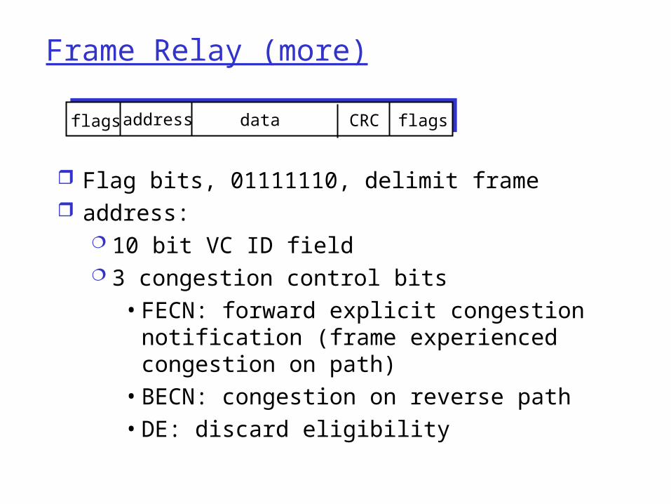
Frame Relay (more)
Flag bits, 01111110, delimit frame address:
10 bit VC ID field 3 congestion control bits
• FECN: forward explicit congestion notification (frame experienced congestion on path)
• BECN: congestion on reverse path• DE: discard eligibility
addressflags data CRC flags

Frame Relay -VC Rate Control
Committed Information Rate (CIR) defined, “guaranteed” for each VC negotiated at VC set up time customer pays based on CIR
DE bit: Discard Eligibility bit Edge FR switch measures traffic rate for
each VC; marks DE bit DE = 0: high priority, rate compliant frame;
deliver at “all costs” DE = 1: low priority, eligible for discard
when congestion
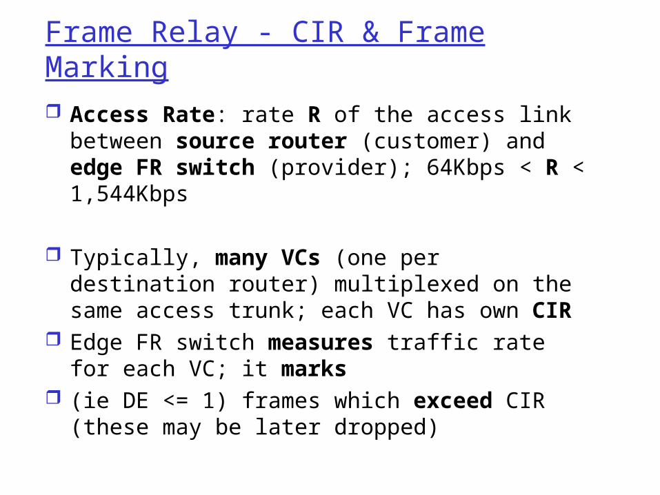
Frame Relay - CIR & Frame Marking
Access Rate: rate R of the access link between source router (customer) and edge FR switch (provider); 64Kbps < R < 1,544Kbps
Typically, many VCs (one per destination router) multiplexed on the same access trunk; each VC has own CIR
Edge FR switch measures traffic rate for each VC; it marks
(ie DE <= 1) frames which exceed CIR (these may be later dropped)

Chapter 5: Summary
principles behind data link layer services: error detection, correction sharing a broadcast channel: multiple access link layer addressing, ARP
various link layer technologies Ethernet hubs, bridges, switches IEEE 802.11 LANs PPP ATM X.25, Frame Relay
journey down the protocol stack now Next stops: security, network
management
Recommended